JP2005293874A - Fuel cell stack - Google Patents
Fuel cell stack Download PDFInfo
- Publication number
- JP2005293874A JP2005293874A JP2004102984A JP2004102984A JP2005293874A JP 2005293874 A JP2005293874 A JP 2005293874A JP 2004102984 A JP2004102984 A JP 2004102984A JP 2004102984 A JP2004102984 A JP 2004102984A JP 2005293874 A JP2005293874 A JP 2005293874A
- Authority
- JP
- Japan
- Prior art keywords
- cell stack
- terminal plate
- fuel cell
- plate
- pair
- Prior art date
- Legal status (The legal status is an assumption and is not a legal conclusion. Google has not performed a legal analysis and makes no representation as to the accuracy of the status listed.)
- Granted
Links
Images
Classifications
-
- Y—GENERAL TAGGING OF NEW TECHNOLOGICAL DEVELOPMENTS; GENERAL TAGGING OF CROSS-SECTIONAL TECHNOLOGIES SPANNING OVER SEVERAL SECTIONS OF THE IPC; TECHNICAL SUBJECTS COVERED BY FORMER USPC CROSS-REFERENCE ART COLLECTIONS [XRACs] AND DIGESTS
- Y02—TECHNOLOGIES OR APPLICATIONS FOR MITIGATION OR ADAPTATION AGAINST CLIMATE CHANGE
- Y02E—REDUCTION OF GREENHOUSE GAS [GHG] EMISSIONS, RELATED TO ENERGY GENERATION, TRANSMISSION OR DISTRIBUTION
- Y02E60/00—Enabling technologies; Technologies with a potential or indirect contribution to GHG emissions mitigation
- Y02E60/30—Hydrogen technology
- Y02E60/50—Fuel cells
Landscapes
- Fuel Cell (AREA)
Abstract
【課題】 燃料電池スタックのターミナルプレートの耐腐食性向上と低コスト化を図る。
【解決手段】 本発明の燃料電池スタック(10)は、単セル(20)を複数積層してなるセルスタック(21)の内部を貫通して反応ガス又は冷却水を供給又は排出する流体通路(71,72)を備えている。流体通路(71,72)はセルスタック(21)の両端に配置された一対のターミナルプレート(31,32)のうちマイナス側のターミナルプレート(31)のみ貫通して入口ポート(71a)及び出口ポート(71b)に連通している。プラス側のターミナルプレート(32)には酸化電流が流れるため、流体通路(71,72)を流れる冷却水又は反応ガスの水分がプラス側のターミナルプレート(32)に触れないように構成することで、ターミナルプレートの耐腐食性向上と低コスト化を両立できる。
【選択図】 図1
PROBLEM TO BE SOLVED: To improve the corrosion resistance and cost of a terminal plate of a fuel cell stack.
A fuel cell stack (10) of the present invention includes a fluid passage (through which a reaction gas or cooling water is supplied or discharged through a cell stack (21) formed by stacking a plurality of single cells (20). 71, 72). The fluid passages (71, 72) pass through only the negative terminal plate (31) of the pair of terminal plates (31, 32) arranged at both ends of the cell stack (21), and enter the inlet port (71a) and the outlet port. (71b). Since an oxidation current flows through the positive side terminal plate (32), the water of the coolant or the reaction gas flowing through the fluid passages (71, 72) is prevented from touching the positive side terminal plate (32). The corrosion resistance of the terminal plate can be improved and the cost can be reduced.
[Selection] Figure 1
Description
本発明は燃料電池スタックに関し、特に、ターミナルプレートの耐腐食性向上と低コスト化を両立するための改良技術に関する。 The present invention relates to a fuel cell stack, and more particularly to an improved technique for achieving both improved corrosion resistance and cost reduction of a terminal plate.
固体高分子型燃料電池スタックは固体高分子電解質膜の両面にそれぞれアノード極とカソード極を対向配置し、更にその外側を一対のセパレータで挟持してなる単セルを所定数積層したスタック構造を成しており、スタック両端部には電力取り出し用の一対のターミナルプレートが配置されている。プラス側のターミナルプレートには酸化電流が流れるため、ターミナルプレートに加湿ガス又は冷却水が触れるとターミナルプレートは腐食する虞がある。ターミナルプレートの耐腐食性を高めるためのスタック構造として、従来から各種のスタック構造が研究されており、例えば、特開2003−163026号公報にはターミナルプレートの冷却水路内側にエンドプレートの材料である樹脂が嵌合してインサートする構成をとることにより加湿ガスや冷却水がターミナルプレートに直接触れないように構成したスタック構造が提案されている。
しかし、特開2003−163026号公報に記載のスタック構造では、プラス側とマイナス側の両方のターミナルプレートを冷却水通路が貫通する構成となっているため、両方のターミナルプレートに腐食対策を講じなければならず、製造コストが高くなる。 However, in the stack structure described in Japanese Patent Application Laid-Open No. 2003-163026, the cooling water passage is configured to penetrate both the positive side and negative side terminal plates. The manufacturing cost becomes high.
そこで、本発明は燃料電池スタックのターミナルプレートの耐腐食性向上と低コスト化を図ることを課題とする。 Therefore, an object of the present invention is to improve the corrosion resistance and reduce the cost of the terminal plate of the fuel cell stack.
上記の課題を解決するため、本発明の燃料電池スタックは、単セルを複数積層して成るセルスタックの内部を貫通して反応ガス又は冷却水を供給又は排出する流体通路を備えた燃料電池スタックであって、流体通路はセルスタックの両端に配置された一対のターミナルプレートのうちマイナス側のターミナルプレートのみ貫通して入口ポート又は出口ポートに連通している。プラス側のターミナルプレートには酸化電流が流れるため、流体通路を流れる冷却水又は反応ガスの水分がプラス側のターミナルプレートに触れないように構成することで、ターミナルプレートの耐腐食性を向上できる。また、還元電流が流れるマイナス側のターミナルプレートよりも酸化電流が流れるプラス側のターミナルプレートの腐食対策をより強化することにより、両極に腐食対策を講じるよりも低コストである。 In order to solve the above-described problems, a fuel cell stack according to the present invention includes a fluid passage through which a reaction gas or cooling water is supplied or discharged through a cell stack formed by stacking a plurality of single cells. The fluid passage passes through only the negative terminal plate of the pair of terminal plates arranged at both ends of the cell stack and communicates with the inlet port or the outlet port. Since an oxidation current flows through the plus side terminal plate, the corrosion resistance of the terminal plate can be improved by configuring the plus side terminal plate so that the cooling water flowing through the fluid passage or the moisture of the reaction gas does not touch the plus side terminal plate. Further, by strengthening the countermeasure against the corrosion of the positive terminal plate through which the oxidation current flows rather than the negative terminal plate through which the reduction current flows, the cost is lower than when the countermeasure against the corrosion is taken at both poles.
ここで、一対のターミナルプレートのうちプラス側のターミナルプレートとセルスタックとの間に水分透過を遮断する遮断プレートを介挿するのが望ましい。還元電流が流れるマイナス側のターミナルプレートよりも酸化電流が流れるプラス側のターミナルプレートへの水分接触をより重点的に抑制することで、耐腐食性向上と低コスト化を両立できる。 Here, it is desirable to insert a blocking plate that blocks moisture permeation between the plus side terminal plate and the cell stack of the pair of terminal plates. By controlling the moisture contact with the positive terminal plate through which the oxidation current flows more focused than the negative terminal plate through which the reduction current flows, both corrosion resistance and cost reduction can be achieved.
本発明によれば流体通路を流れる冷却水又は反応ガスの水分がプラス側のターミナルプレートに接しないように構成することで、ターミナルプレートの耐腐食性向上と低コスト化を実現できる。 According to the present invention, it is possible to realize an improvement in corrosion resistance and cost reduction of the terminal plate by configuring so that the cooling water or the water of the reaction gas flowing through the fluid passage does not contact the positive terminal plate.
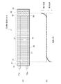
図1は本実施形態の燃料電池スタックの説明図である。同図(a)に示すように、燃料電池スタック10は、電解質膜を一対の電極で挟持し、更にその外側を一対の導電性セパレータで挟持してなる単セル20を複数積層してなるセルスタック21を備えている。セルスタック21の内部には単セル20に反応ガス(燃料ガス、酸化ガス)又は冷却水を供給する流体供給通路71と、単セル20の電池反応に供した反応ガス又は単セル20との間で熱交換を行った冷却水を排出する流体排出通路72が貫設されている。セルスタック21の両端部には電力取り出し用の一対のターミナルプレート31,32が配置されている。ターミナルプレート31,32の外側は絶縁プレート41,42を介して一対のエンドプレート51,52によって挟装されている。燃料電池スタック10のマイナス側のエンドプレート51には、流体供給通路71の入口ポート71aと、流体排出通路72の出口ポート72aが形成されている。
FIG. 1 is an explanatory diagram of a fuel cell stack according to this embodiment. As shown in FIG. 1A, the fuel cell stack 10 is a cell formed by stacking a plurality of
尚、反応ガス供給通路及び冷却水供給通路と、反応ガス排出通路及び冷却水排出通路はそれぞれ異なる流体通路であるが、説明の便宜上、前者を流体供給通路71と総称し、後者を流体排出通路72と総称する。また、流体供給通路71と流体排出通路72を区別する必要がない場合には単に流体通路71,72と総称する。
The reactive gas supply passage and the cooling water supply passage, and the reactive gas discharge passage and the cooling water discharge passage are different fluid passages. However, for convenience of explanation, the former is generically referred to as the
流体通路71,72は一対のターミナルプレート31,32のうちマイナス側のターミナルプレート31のみ貫通して入口ポート71a及び出口ポート72aに連通しており、プラス側のターミナルプレート32には流体通路71,72の入口ポート及び出口ポートは形成されていない。かかる構成により、流体通路71,72を流れる冷却水、又は電池反応等で生じた反応ガス中の水分がプラス側のターミナルプレート32に触れるのを防止できる。ターミナルプレート32への水分の接触をより効果的に抑制するには、ターミナルプレート32とセルスタック21との間に水分透過を遮断する遮断プレート60を介挿するのが望ましい。遮断プレート60としては、セルスタック21とターミナルプレート32とを電気的に接続することができ、且つ水分透過を遮断できるプレートであれば、特に限定されるものではなく、例えば、導電プレート等が好適である。
The
同図(b)に示すように、マイナス側のターミナルプレート31とその付近の単セル20には還元電流が局所的に流れるのに対して、プラス側のターミナルプレート32とその付近の単セル20には酸化電流が局所的に流れる。酸化電流が多く流れるプラス側のターミナルプレート32に水分が触れると腐食が進行し易くなるため、ターミナルプレート31,32の腐食対策としては、主として、プラス側に重点をおく必要がある。上述の構成によれば、燃料電池スタック10の両極(プラス側、マイナス側)をそれぞれ同程度に腐食対策を講じるのではなく、より腐食し易いプラス側の腐食対策に重点をおくことで、ターミナルプレートの耐腐食性向上と低コスト化を両立できる。
As shown in FIG. 5B, the reduction current locally flows in the minus
10…燃料電池スタック 20…単セル 21…セルスタック 31,32…ターミナルプレート 41,42…絶縁プレート 51,52…エンドプレート 60…遮断プレート 71,72…流体通路
DESCRIPTION OF SYMBOLS 10 ...
Claims (2)
2. The fuel cell stack according to claim 1, wherein a blocking plate that blocks moisture permeation is interposed between a positive terminal plate of the pair of terminal plates and the cell stack. .
Priority Applications (6)
| Application Number | Priority Date | Filing Date | Title |
|---|---|---|---|
| JP2004102984A JP4614120B2 (en) | 2004-03-31 | 2004-03-31 | Fuel cell stack |
| PCT/JP2005/005611 WO2005099019A1 (en) | 2004-03-31 | 2005-03-18 | Fuel cell stack |
| CA002528689A CA2528689C (en) | 2004-03-31 | 2005-03-18 | Fuel cell stack |
| CNB2005800007052A CN100370645C (en) | 2004-03-31 | 2005-03-18 | fuel cell stack |
| DE112005000023T DE112005000023B4 (en) | 2004-03-31 | 2005-03-18 | fuel cell stack |
| US11/311,276 US7855026B2 (en) | 2004-03-31 | 2005-12-20 | Fuel cell stack |
Applications Claiming Priority (1)
| Application Number | Priority Date | Filing Date | Title |
|---|---|---|---|
| JP2004102984A JP4614120B2 (en) | 2004-03-31 | 2004-03-31 | Fuel cell stack |
Publications (2)
| Publication Number | Publication Date |
|---|---|
| JP2005293874A true JP2005293874A (en) | 2005-10-20 |
| JP4614120B2 JP4614120B2 (en) | 2011-01-19 |
Family
ID=35326598
Family Applications (1)
| Application Number | Title | Priority Date | Filing Date |
|---|---|---|---|
| JP2004102984A Expired - Lifetime JP4614120B2 (en) | 2004-03-31 | 2004-03-31 | Fuel cell stack |
Country Status (2)
| Country | Link |
|---|---|
| JP (1) | JP4614120B2 (en) |
| CN (1) | CN100370645C (en) |
Cited By (6)
| Publication number | Priority date | Publication date | Assignee | Title |
|---|---|---|---|---|
| JP2007311343A (en) * | 2006-05-15 | 2007-11-29 | Gm Global Technology Operations Inc | Non-permeable low contact resistance shim for composite fuel cell stack |
| JP2010251166A (en) * | 2009-04-17 | 2010-11-04 | Honda Motor Co Ltd | Fuel cell stack |
| CN105047946A (en) * | 2015-06-30 | 2015-11-11 | 中国东方电气集团有限公司 | Battery stack and its cells |
| KR20160058034A (en) * | 2014-11-14 | 2016-05-24 | 도요타지도샤가부시키가이샤 | Fuel cell stack |
| DE102018111481A1 (en) | 2017-06-15 | 2018-12-20 | Toyota Jidosha Kabushiki Kaisha | fuel cell stack |
| US10243230B2 (en) | 2014-11-10 | 2019-03-26 | Toyota Jidosha Kabushiki Kaisha | Fuel battery |
Citations (3)
| Publication number | Priority date | Publication date | Assignee | Title |
|---|---|---|---|---|
| JPH08167424A (en) * | 1994-12-13 | 1996-06-25 | Fuji Electric Co Ltd | Solid polymer electrolyte fuel cell |
| JPH08306380A (en) * | 1995-05-09 | 1996-11-22 | Fuji Electric Co Ltd | Stacked fuel cell |
| JP2003346869A (en) * | 2002-05-24 | 2003-12-05 | Honda Motor Co Ltd | Fuel cell stack |
Family Cites Families (2)
| Publication number | Priority date | Publication date | Assignee | Title |
|---|---|---|---|---|
| JP2002216806A (en) * | 2001-01-23 | 2002-08-02 | Honda Motor Co Ltd | Polymer electrolyte fuel cell stack |
| JP4621370B2 (en) * | 2001-02-28 | 2011-01-26 | 株式会社東芝 | Fuel cell stack structure |
-
2004
- 2004-03-31 JP JP2004102984A patent/JP4614120B2/en not_active Expired - Lifetime
-
2005
- 2005-03-18 CN CNB2005800007052A patent/CN100370645C/en not_active Expired - Lifetime
Patent Citations (3)
| Publication number | Priority date | Publication date | Assignee | Title |
|---|---|---|---|---|
| JPH08167424A (en) * | 1994-12-13 | 1996-06-25 | Fuji Electric Co Ltd | Solid polymer electrolyte fuel cell |
| JPH08306380A (en) * | 1995-05-09 | 1996-11-22 | Fuji Electric Co Ltd | Stacked fuel cell |
| JP2003346869A (en) * | 2002-05-24 | 2003-12-05 | Honda Motor Co Ltd | Fuel cell stack |
Cited By (14)
| Publication number | Priority date | Publication date | Assignee | Title |
|---|---|---|---|---|
| US8323851B2 (en) | 2006-05-15 | 2012-12-04 | GM Global Technology Operations LLC | Non-permeable low contact resistance shim for composite fuel cell stacks |
| JP2007311343A (en) * | 2006-05-15 | 2007-11-29 | Gm Global Technology Operations Inc | Non-permeable low contact resistance shim for composite fuel cell stack |
| JP2010251166A (en) * | 2009-04-17 | 2010-11-04 | Honda Motor Co Ltd | Fuel cell stack |
| US10243230B2 (en) | 2014-11-10 | 2019-03-26 | Toyota Jidosha Kabushiki Kaisha | Fuel battery |
| KR101941739B1 (en) | 2014-11-14 | 2019-01-23 | 도요타지도샤가부시키가이샤 | Fuel cell stack |
| KR20160058034A (en) * | 2014-11-14 | 2016-05-24 | 도요타지도샤가부시키가이샤 | Fuel cell stack |
| JP2016096033A (en) * | 2014-11-14 | 2016-05-26 | トヨタ自動車株式会社 | Fuel cell stack |
| US10033051B2 (en) | 2014-11-14 | 2018-07-24 | Toyota Jidosha Kabushiki Kaisha | Fuel cell stack |
| CN105047946B (en) * | 2015-06-30 | 2017-10-27 | 中国东方电气集团有限公司 | Battery pile and its battery unit |
| CN105047946A (en) * | 2015-06-30 | 2015-11-11 | 中国东方电气集团有限公司 | Battery stack and its cells |
| KR20180136893A (en) | 2017-06-15 | 2018-12-26 | 도요타지도샤가부시키가이샤 | Fuel cell stack |
| DE102018111481A1 (en) | 2017-06-15 | 2018-12-20 | Toyota Jidosha Kabushiki Kaisha | fuel cell stack |
| US10559833B2 (en) | 2017-06-15 | 2020-02-11 | Toyota Jidosha Kabushiki Kaisha | Fuel cell stack |
| DE102018111481B4 (en) | 2017-06-15 | 2026-03-19 | Toyota Jidosha Kabushiki Kaisha | Fuel cell stack |
Also Published As
| Publication number | Publication date |
|---|---|
| CN100370645C (en) | 2008-02-20 |
| CN1820388A (en) | 2006-08-16 |
| JP4614120B2 (en) | 2011-01-19 |
Similar Documents
| Publication | Publication Date | Title |
|---|---|---|
| JP4630529B2 (en) | Fuel cell system | |
| JP5180484B2 (en) | Fuel cell stack | |
| US20190131636A1 (en) | Bipolar plate which has reactant gas channels with variable cross-sectional areas, fuel cell stack, and vehicle comprising such a fuel cell stack | |
| JP4417224B2 (en) | Fuel cell stack | |
| JP4820068B2 (en) | Fuel cell stack | |
| JP7033981B2 (en) | Fuel cell stack | |
| JP4614120B2 (en) | Fuel cell stack | |
| US10186717B2 (en) | Metal separation plate for fuel cell stack and fuel cell stack having the same | |
| JP2007305339A (en) | Electrolyte circulating battery cell | |
| JP2000164227A (en) | Gas manifold integrated separator and fuel cell | |
| JP2006120572A (en) | Fuel cell | |
| JP2005285402A (en) | Fuel cell stack | |
| JP2010282792A (en) | Fuel cell stack | |
| JP5312270B2 (en) | Fuel cell stack | |
| JP2009170286A (en) | Fuel cell | |
| JP2005216700A (en) | FUEL CELL STACK, SEPARATOR INTERMEDIATE AND SEPARATOR MANUFACTURING METHOD | |
| JP5042507B2 (en) | Fuel cell | |
| JP5016228B2 (en) | Fuel cell | |
| JP2004087190A (en) | Solid polymer cell assembly | |
| JP2006236612A (en) | Fuel cell | |
| KR20200000913A (en) | The separator for fuel cell | |
| JP4281330B2 (en) | Polymer electrolyte fuel cell | |
| KR102775074B1 (en) | Fuel cell stack and Fuel cell system including the same | |
| US7855026B2 (en) | Fuel cell stack | |
| JP4575117B2 (en) | Fuel cell stack |
Legal Events
| Date | Code | Title | Description |
|---|---|---|---|
| A621 | Written request for application examination |
Free format text: JAPANESE INTERMEDIATE CODE: A621 Effective date: 20061127 |
|
| A131 | Notification of reasons for refusal |
Free format text: JAPANESE INTERMEDIATE CODE: A131 Effective date: 20100519 |
|
| TRDD | Decision of grant or rejection written | ||
| A01 | Written decision to grant a patent or to grant a registration (utility model) |
Free format text: JAPANESE INTERMEDIATE CODE: A01 Effective date: 20100924 |
|
| A01 | Written decision to grant a patent or to grant a registration (utility model) |
Free format text: JAPANESE INTERMEDIATE CODE: A01 |
|
| A61 | First payment of annual fees (during grant procedure) |
Free format text: JAPANESE INTERMEDIATE CODE: A61 Effective date: 20101007 |
|
| R151 | Written notification of patent or utility model registration |
Ref document number: 4614120 Country of ref document: JP Free format text: JAPANESE INTERMEDIATE CODE: R151 |
|
| FPAY | Renewal fee payment (event date is renewal date of database) |
Free format text: PAYMENT UNTIL: 20131029 Year of fee payment: 3 |
|
| EXPY | Cancellation because of completion of term |