JP2005293857A - Fuel cell system - Google Patents
Fuel cell system Download PDFInfo
- Publication number
- JP2005293857A JP2005293857A JP2004102573A JP2004102573A JP2005293857A JP 2005293857 A JP2005293857 A JP 2005293857A JP 2004102573 A JP2004102573 A JP 2004102573A JP 2004102573 A JP2004102573 A JP 2004102573A JP 2005293857 A JP2005293857 A JP 2005293857A
- Authority
- JP
- Japan
- Prior art keywords
- unit
- units
- hollow shaft
- fuel cell
- shaft member
- Prior art date
- Legal status (The legal status is an assumption and is not a legal conclusion. Google has not performed a legal analysis and makes no representation as to the accuracy of the status listed.)
- Pending
Links
Images

Classifications
-
- Y—GENERAL TAGGING OF NEW TECHNOLOGICAL DEVELOPMENTS; GENERAL TAGGING OF CROSS-SECTIONAL TECHNOLOGIES SPANNING OVER SEVERAL SECTIONS OF THE IPC; TECHNICAL SUBJECTS COVERED BY FORMER USPC CROSS-REFERENCE ART COLLECTIONS [XRACs] AND DIGESTS
- Y02—TECHNOLOGIES OR APPLICATIONS FOR MITIGATION OR ADAPTATION AGAINST CLIMATE CHANGE
- Y02E—REDUCTION OF GREENHOUSE GAS [GHG] EMISSIONS, RELATED TO ENERGY GENERATION, TRANSMISSION OR DISTRIBUTION
- Y02E60/00—Enabling technologies; Technologies with a potential or indirect contribution to GHG emissions mitigation
- Y02E60/30—Hydrogen technology
- Y02E60/50—Fuel cells
Landscapes
- Fuel Cell (AREA)
Abstract
【課題】 スタックの寿命を延ばすことができる燃料電池システムの提供。
【解決手段】(1) セルを複数積層したユニット4を複数積層して構成したスタック2と、スタックを構成する複数のユニット4のうちの任意の1以上のユニットを発電するユニット4Aとして選択し選択された発電するユニットのみを電気的に互いに接続する外部回路制御装置23と、発電するユニット4Aのみに燃料ガスを供給する燃料ガス供給部29と、を有する燃料電池システム1。(2)外部回路制御装置23は、発電するユニット4Aと、発電するユニット4Aの数を変更することができる。
【選択図】 図1PROBLEM TO BE SOLVED: To provide a fuel cell system capable of extending the life of a stack.
[MEANS FOR SOLVING PROBLEMS] (1) A stack 2 configured by stacking a plurality of units 4 in which a plurality of cells are stacked, and any one or more units among the plurality of units 4 configuring the stack are selected as a unit 4A for generating power. A fuel cell system 1 having an external circuit control device 23 that electrically connects only selected power generating units to each other and a fuel gas supply unit 29 that supplies fuel gas only to the power generating unit 4A. (2) The external circuit control device 23 can change the number of units 4A that generate power and the number of units 4A that generate power.
[Selection] Figure 1
Description
本発明は燃料電池システムに関する。 The present invention relates to a fuel cell system.
燃料電池、膜−電極アッセンブリ(MEA:Membrane-Electrode Assembly )とセパレータとの積層体からなる。膜−電極アッセンブリは、イオン交換膜からなる電解質膜とこの電解質膜の一面に配置された触媒層からなる電極(アノード、燃料極)および電解質膜の他面に配置された触媒層からなる電極(カソード、空気極)とからなる。セパレータには、アノードに燃料ガス(水素)を供給するための燃料ガス流路が形成され、カソードに酸化ガス(酸素、通常は空気)を供給するための酸化ガス流路が形成されている。膜−電極アッセンブリとセパレータを重ねた単セルを1層以上重ねてモジュールとし、モジュールを積層して、スタックを構成する。 It consists of a laminate of a fuel cell, a membrane-electrode assembly (MEA) and a separator. The membrane-electrode assembly includes an electrolyte membrane composed of an ion exchange membrane, an electrode composed of a catalyst layer disposed on one surface of the electrolyte membrane (anode, fuel electrode), and an electrode composed of a catalyst layer disposed on the other surface of the electrolyte membrane ( Cathode, air electrode). In the separator, a fuel gas passage for supplying fuel gas (hydrogen) to the anode is formed, and an oxidizing gas passage for supplying oxidizing gas (oxygen, usually air) to the cathode. One or more single cells in which a membrane-electrode assembly and a separator are stacked are stacked to form a module, and the modules are stacked to form a stack.
一般的には、一つの燃料電池スタックは、要求出力に応じ、複数のセルを直列に接続した積層体により構成される。そして、スタックにおいて、一括導入された燃料ガス、酸化ガスは各セルに分配導入され、全てのセルが同時に発電する。
また、上記スタック型とは別に、特開2003−115312号公報は、複数のセルをスタック化せずに別々に配置し、各セルを複数の接続端子を介して接続モジュールに接続し、接続モジュールで接続端子の間の電気的接続を変えて出力電圧を変化させるようにした燃料電池装置を開示している。
In general, one fuel cell stack is configured by a stacked body in which a plurality of cells are connected in series according to a required output. In the stack, the fuel gas and the oxidizing gas introduced together are distributed and introduced into each cell, and all the cells generate power simultaneously.
Further, apart from the stack type, Japanese Patent Laid-Open No. 2003-115312 discloses that a plurality of cells are arranged separately without being stacked, and each cell is connected to a connection module via a plurality of connection terminals. The fuel cell device is disclosed in which the output voltage is changed by changing the electrical connection between the connection terminals.
しかし、一般的なスタック型燃料電池では、全セルが直列に接続されているため、積層されたセルの1つにでも損傷があると、スタック全体の発電運転が不可能になるという問題がある。また、外部負荷によって要求電圧が変化し、それに応じて各セルの出力も変化されるので、セルの一定出力運転が困難であり、セルの耐久性を高く維持するのが難しい。
また、スタックに代えて特開2003−115312号公報のようにセルを別々に配置すると、燃料電池装置の配置に要するスペースが膨大になり、かつそれへのガス供給、排出の配管やホースを設置するスペースも膨大になる。
Further, if cells are arranged separately as in JP-A-2003-115312 instead of a stack, the space required for the arrangement of the fuel cell device becomes enormous, and gas supply and discharge pipes and hoses are installed for it. The space to do becomes huge.
本発明が解決しようとする問題点は、配置スペースを小とするために(特開2003−115312号公報のようにセルを別々に配置せずに)セルのスタック化を維持した場合、スタック中の1つのセルにでも損傷があると、スタック全体の発電運転が不可能になること、および、セルの一定出力運転が困難であり、セルの耐久性を高く維持するのが難しいという問題である。
本発明の目的は、(特開2003−115312号公報のようにセルを別々に配置せずに)セルのスタック化を維持し、スタック中の任意の特定のセルに不具合が生じても、スタックの発電運転を継続でき、スタックの寿命を従来に比べて延ばすことができる燃料電池システムを提供することにある。
本発明のもう一つの目的は、(特開2003−115312号公報のようにセルを別々に配置せずに)セルのスタック化を維持し、スタック中の任意の特定のセルに不具合が生じても、スタックの発電運転を継続でき、スタックの寿命を従来に比べて延ばすことができると共に、セルの運転を一定出力運転に近づけることができ、それによってもスタックの寿命を延ばすことができる、燃料電池システムを提供することにある。
The problem to be solved by the present invention is that, in order to reduce the arrangement space (when cells are not arranged separately as in JP-A-2003-115312), the stacking of cells is maintained. If even one of the cells is damaged, it is impossible to generate electricity for the entire stack, and it is difficult to maintain a constant output of the cell, and it is difficult to maintain high durability of the cell. .
An object of the present invention is to maintain stacking of cells (without arranging cells separately as in Japanese Patent Application Laid-Open No. 2003-115312), and even if a failure occurs in any specific cell in the stack, the stack It is an object of the present invention to provide a fuel cell system that can continue the power generation operation and extend the life of the stack as compared with the conventional one.
Another object of the present invention is to maintain the cell stacking (without arranging the cells separately as in Japanese Patent Application Laid-Open No. 2003-115312), and any specific cell in the stack has a problem. However, it is possible to continue the power generation operation of the stack, extend the life of the stack compared to the conventional, and the operation of the cell can be brought closer to the constant output operation, which can also extend the life of the stack It is to provide a battery system.
上記課題を解決する、そして上記目的を達成する、本発明はつぎの通りである。
(1) 単セルを複数積層したユニットを複数積層して構成したスタックと、
前記スタックを構成する複数のユニットのうちの任意の1以上のユニットを発電するユニットとして選択し選択された発電するユニットのみを電気的に互いに接続する外部回路制御装置と、
前記スタックを構成する複数のユニットのうち前記選択された1以上の発電するユニットのみに燃料ガスを供給する燃料ガス供給部と、
を有する燃料電池システム。
(2) 前記外部回路制御装置が、
前記スタックを構成する複数のユニットの各ユニットに設けられた外部回路と、
複数の接点を有し前記外部回路と接続された接点装置と、
前記複数のユニットのうちの任意の1以上のユニットを発電するユニットとして選択し選択された発電するユニットのみが電気的に互いに接続されるように前記接点装置の複数の接点の開閉を制御する電子制御装置と、を有する(1)記載の燃料電池システム。
(3) 前記燃料ガス供給部は、第1、第2の中空軸部材を有しており、
該第1、第2の中空軸部材は全ユニットにわたってユニット積層方向に延びており、
該第1、第2の中空軸部材の一方の中空軸部材の外周面は他方の中空軸部材の内周面に摺動可能に接触しており、
該第1、第2の中空軸部材の少なくとも一方の中空軸部材は軸芯まわりに回動可能であり、
該第1、第2の中空軸部材には各ユニットに対応する位置に開口が設けられており、
各ユニットに対応する位置に設けられた前記第1の中空軸部材の開口と前記第2の中空軸部材の開口とは前記発電するユニットのみに燃料ガスを供給するように回転方向位置と数が定められている、(1)記載の燃料電池システム。
(4) 前記燃料ガス供給部の、前記回動可能な中空軸部材は、回動駆動装置に連結されており、前記外部回路制御装置は、発電するユニットを選択した時に、該発電するユニットだけに燃料ガスを供給するように前記回動駆動装置による前記回動可能な中空軸部材の回動を制御する、(3)記載の燃料電池システム。
(5) 前記燃料ガス供給部は、前記スタックの各ユニットの各セルのセル面内方向中央部に設けられている(1)記載の燃料電池システム。
(6) 前記発電するユニットを電気的に直列に接続した(1)記載の燃料電池システム。
(7) 前記発電するユニットを電気的に並列に接続した(1)記載の燃料電池システム。
(8) 前記外部回路制御装置は、各セルのモニタ電圧を予め定めたセル電圧下限値を下回ったか否かを判定し、任意の特定セルのモニタ電圧が前記セル電圧下限値を下回ったと判定した場合には前記回動駆動装置を駆動して前記回動可能な中空軸部材を回動し、発電するユニットを変更する(2)記載の燃料電池システム。
(9) 前記外部回路制御装置は、各発電するユニットのユニット出力電圧が予め定めたユニット出力電圧下限値を下回ったか否かを判定し、任意の特定ユニットのユニット出力電圧が前記ユニット出力電圧下限値を下回ったと判定した場合には前記回動駆動装置を駆動して前記回動可能な中空軸部材を回動し、発電するユニットを変更する(3)記載の燃料電池システム。
(10) 前記外部回路制御装置は、変化する燃料電池出力要求電力に応じた必要電圧および必要発電ユニット数を満足するように、前記回動駆動装置による前記回動可能な中空軸部材の回動を制御して発電ユニット数を変更する、(3)記載の燃料電池システム。
The present invention for solving the above problems and achieving the above object is as follows.
(1) a stack configured by stacking a plurality of units each including a plurality of single cells;
An external circuit control device that selects only one or more selected power generation units as a power generation unit from among a plurality of units constituting the stack, and electrically connects only the selected power generation units;
A fuel gas supply unit that supplies fuel gas only to the one or more selected power generating units among the plurality of units constituting the stack;
A fuel cell system.
(2) The external circuit control device is
An external circuit provided in each unit of the plurality of units constituting the stack;
A contact device having a plurality of contacts and connected to the external circuit;
An electronic device that selects any one or more units of the plurality of units as a unit for generating power, and controls opening and closing of the plurality of contacts of the contact device so that only the selected power generating unit is electrically connected to each other. A fuel cell system according to (1), comprising a control device.
(3) The fuel gas supply unit includes first and second hollow shaft members,
The first and second hollow shaft members extend in the unit stacking direction over all units,
The outer peripheral surface of one hollow shaft member of the first and second hollow shaft members is slidably in contact with the inner peripheral surface of the other hollow shaft member,
At least one hollow shaft member of the first and second hollow shaft members is rotatable about an axis;
The first and second hollow shaft members are provided with openings at positions corresponding to the respective units,
The opening of the first hollow shaft member and the opening of the second hollow shaft member provided at a position corresponding to each unit have a rotational direction position and a number so as to supply fuel gas only to the power generating unit. The fuel cell system according to (1), which is defined.
(4) The rotatable hollow shaft member of the fuel gas supply unit is connected to a rotation drive device, and when the external circuit control unit selects a unit to generate power, only the unit that generates power is selected. The fuel cell system according to (3), wherein the rotation of the rotatable hollow shaft member by the rotation driving device is controlled so as to supply fuel gas to the fuel cell system.
(5) The fuel cell system according to (1), wherein the fuel gas supply unit is provided at a center portion in the cell plane direction of each cell of each unit of the stack.
(6) The fuel cell system according to (1), wherein the power generating units are electrically connected in series.
(7) The fuel cell system according to (1), wherein the power generating units are electrically connected in parallel.
(8) The external circuit control device determines whether or not the monitor voltage of each cell falls below a predetermined cell voltage lower limit value, and determines that the monitor voltage of any specific cell falls below the cell voltage lower limit value. In this case, the fuel cell system according to (2), wherein the rotation driving device is driven to rotate the rotatable hollow shaft member to change the unit for generating power.
(9) The external circuit control device determines whether or not the unit output voltage of each power generating unit falls below a predetermined unit output voltage lower limit value, and the unit output voltage of any specific unit is the unit output voltage lower limit value. The fuel cell system according to (3), wherein when it is determined that the value is lower than the value, the rotation driving device is driven to rotate the rotatable hollow shaft member to change the unit for generating power.
(10) The external circuit controller rotates the rotatable hollow shaft member by the rotation driving device so as to satisfy the required voltage and the required number of power generation units according to the changing fuel cell output required power. The fuel cell system according to (3), wherein the number of power generation units is changed by controlling
上記(1)〜(10)の燃料電池システムによれば、セルを複数積層したユニットを複数積層してスタックとしたので、燃料電池の設置スペースをコンパクトにすることができる。また、外部回路制御装置と燃料ガス供給部を設けたので、スタック中の任意の特定セルが損傷した場合、その特定セルを含んでいるユニットを外部回路制御装置によって外部回路から除去し、そのユニットへの燃料ガス供給を燃料ガス供給部によって停止することによって、そのユニットの発電を停止でき、残りのユニットによって、正常運転を続けることができる。スペアユニットを予めスタック中に組み込んでおくことにより、スタックの寿命が延びる。
また、上記(10)の燃料電池システムによれば、スタックに損傷セルが生じていない場合でも、外部負荷から要求される発電電圧に応じて、外部回路制御装置と燃料ガス供給部によって、発電するユニット数を変化させることにより、各セルをほぼ一定出力運転に維持して外部負荷の変動に対応することができる。各セルがほぼ一定出力運転の結果、各セルが損傷を起こしにくくなり、スタックとしての寿命も延びる。
According to the fuel cell system of (1) to (10) above, since a plurality of units in which a plurality of cells are stacked are stacked to form a stack, the installation space for the fuel cell can be made compact. In addition, since the external circuit control device and the fuel gas supply unit are provided, when any specific cell in the stack is damaged, the unit including the specific cell is removed from the external circuit by the external circuit control device, and the unit By stopping the fuel gas supply to the fuel gas supply unit, power generation of the unit can be stopped, and normal operation can be continued by the remaining units. By incorporating a spare unit in the stack in advance, the life of the stack is extended.
Further, according to the fuel cell system of (10), even if no damaged cell is generated in the stack, the external circuit control device and the fuel gas supply unit generate power according to the power generation voltage required from the external load. By changing the number of units, each cell can be maintained at a substantially constant output operation to cope with fluctuations in the external load. As a result of the almost constant output operation of each cell, each cell is less likely to be damaged, and the life as a stack is extended.
以下に、本発明の燃料電池システムを、図1〜図10を参照して説明する。
本発明の燃料電池システムが適用される燃料電池は、たとえば固体高分子電解質型燃料電池である。該燃料電池は、たとえば燃料電池自動車に搭載される。ただし、自動車以外に用いられてもよい。
The fuel cell system of the present invention will be described below with reference to FIGS.
The fuel cell to which the fuel cell system of the present invention is applied is, for example, a solid polymer electrolyte fuel cell. The fuel cell is mounted on, for example, a fuel cell vehicle. However, it may be used other than an automobile.
図1に示すように、本発明の燃料電池システム1は、セル3を複数積層したユニット4を複数積層して構成したスタック2と、スタック2を構成する複数のユニット4のうちの任意の1以上のユニットを発電するユニット4Aとして選択し選択された発電するユニット4Aのみを電気的に互いに接続する外部回路制御装置23と、スタック2を構成する複数のユニット4のうち選択された1以上の発電するユニット4Aのみに燃料ガスを供給する燃料ガス供給部29と、を有する。
As shown in FIG. 1, the
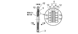
セル3は、膜−電極アッセンブリ5(MEA:Membrane-Electrode Assembly )とセパレータ12との積層体からなる。MEA5は、イオン交換膜からなる電解質膜6と、この電解質膜6の一面に配置されたアノード7および電解質膜6の他面に配置された触媒層カソード8とからなる。図6に示すように、MEA5とセパレータ12との間には、アノード側、カソード側に、それぞれ、ガスを拡散する拡散層9、10が設けられることが望ましい。
各発電するユニット4において、各セル3の、アノード7側では、水素を水素イオン(プロトン)と電子にする電離反応が行われ、水素イオンは電解質膜6中をカソード8側に移動し、カソード8側では酸素と水素イオンおよび電子(隣りのMEAのアノードで生成した電子がセパレータを通してくる、またはセル積層方向一端のセルのアノードで生成した電子が外部回路を通して他端のセルのカソードにくる)から水を生成するつぎの反応が行われ、かくして発電が行われる。
アノード側:H2 →2H+ +2e-
カソード側:2H+ +2e- +(1/2)O2 →H2 O
The
In each power generating
Anode side: H 2 → 2H + + 2e −
Cathode side: 2H + + 2e − + (1/2) O 2 → H 2 O
図1に示すように、複数のセル3を積層してユニット4とし、複数のユニット4をセル積層方向に積層してスタック2とする。ユニット4間には集電板22を配置してもよい。ただし、集電板22を配置しないで各ユニット4の端部セル3のセパレータ12から電流を取り出してもよい。また、ユニット4間には絶縁板を設けて、各ユニット4を電気的に互いに独立させてもよい。
スタック2のセル積層方向両端には絶縁板11を配置し、そのセル積層方向外側にエンドプレートを配置し、両端エンドプレートをセル積層方向に締め付け、締結手段で締結する。
As shown in FIG. 1, a plurality of
Insulating
セパレータ12には、アノード7に燃料ガス(水素)を供給するための燃料ガス流路13が形成され、カソード8に酸化ガス(酸素、通常は空気)を供給するための酸化ガス流路14が形成されている。また、セパレータ12のガス流路13、14と反対側の面には冷却水を流すための冷却水流路15が形成される。
In the
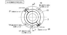
スタック2には、セル積層方向に延びる、入側の燃料ガスマニホールド16(燃料ガスマニホールド16は、燃料ガス供給部29の内側の中空軸部材の中に形成されたスペースからなる)、出側の燃料ガスマニホールド17、入側の酸化ガスマニホールド18、出側の酸化ガスマニホールド19、入側の冷却水マニホールド20、出側の冷却水マニホールド21が形成される。
The
図7に示すように、燃料ガスは入側の燃料ガスマニホールド16から、全ユニット4のうち発電するユニット4Aのみの、セル3の燃料ガス流路13に流れて発電で一部消費され、消費されなかった燃料ガスは燃料ガス流路13から出側の燃料ガスマニホールド17へと流れる。
図8に示すように、酸化ガスは入側の酸化ガスマニホールド18から、全ユニット4の、セル3の酸化ガス流路14に流れて発電で一部消費され、消費されなかった酸化ガスは酸化ガス流路14から出側の酸化ガスマニホールド19へと流れる。
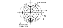
図5に示すように、冷却水は入側の冷却水マニホールド20から、全ユニット4の、セルの冷却水流路15に流れ、冷却水流路15から出側の冷却水マニホールド21へと流れる。
As shown in FIG. 7, the fuel gas flows from the
As shown in FIG. 8, the oxidizing gas flows from the inlet side oxidizing
As shown in FIG. 5, the cooling water flows from the cooling
外部回路制御装置23は、スタック2を構成する複数のユニット4の各ユニットに設けられた外部回路24と、複数の接点26を有し外部回路24と接続された接点装置(接点モジュール)25と、複数のユニット4のうちの任意の1以上のユニットを発電するユニット4Aとして選択し選択された発電するユニット4Aのみが電気的に互いに直列または並列に接続されるように接点装置25の複数の接点26の開閉を制御する電子制御装置27と、を有する。
スタック2は、外部回路制御装置23を介して外部負荷28と電気的に接続している。したがって、外部回路制御装置23は、スタック2と外部負荷28とを結ぶ外部回路の途中に設けられる。外部負荷28は、たとえば車両の駆動モータであり、その負荷の大きさは変化する。
The external
The
たとえば、図1はスタック2のユニット数が3個で、左から順に第1ユニット、第2ユニット、第3ユニットとする。第1ユニットのみを発電するユニット4Aとするには、接点26A、26B、26F、26Gが閉で、接点26E、26C、26Dを開とする。また、第1ユニットと第2ユニットのみを発電するユニット4Aとするには、接点26A、26B、26C、26Gが閉で、接点26E、26F、26Dを開とする。また、第1ユニットと第2ユニットと第3ユニットの全ユニットを発電するユニット4Aとするには、接点26A、26Dが閉で、接点26B、26C、26E、26F、26Gを開とするといった具合である。ただし、発電するユニット4Aの組み合わせと変化は、この例に限るものではない。
For example, in FIG. 1, the number of units in the
燃料ガス供給部29は、複数の、少なくとも2つの、中空軸部材を有しており、したがって、少なくとも第1の中空軸部材30と第2の中空軸部材31を有している。中空軸部材の数は3以上でもよい。以下の説明では中空軸部材の数が2の場合で説明する。
第1、第2の中空軸部材30、31は、全ユニット4にわたって、ユニット積層方向に延びている。
複数の中空軸部材30、31は、同一の軸芯を有し、互いに重ねられている。あるいは燃料ガスの外部への漏れを防止するため、中空軸部材31の内周と30の外周を押し当てるように偏心し、重ねられている。第1、第2の中空軸部材30、31の一方の中空軸部材30の外周面は他方の中空軸部材31の内周面に摺動可能に接触している。
第1、第2の中空軸部材30、31の少なくとも一方の中空軸部材30、望ましくは、最外周の中空軸部材31以外の中空軸部材30は、軸芯まわりに回動可能である。最外周の中空軸部材31は、非回動部材であるセル3とのシール上、非回動部材であることが望まれる。
The fuel
The first and second
The plurality of
The
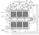
第1の中空軸部材30には各ユニット4に対応する位置に第1の開口32が設けられており、第2の中空軸部材31には各ユニット4に対応する位置に第2の開口33が設けられている。
各ユニット4に対応する位置に設けられた第1の中空軸部材30の開口32と第2の中空軸部材31の開口33とは、発電するユニット4Aのみに燃料ガスを供給するように回転方向位置と数が定められている。
The first
The
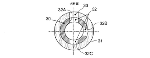
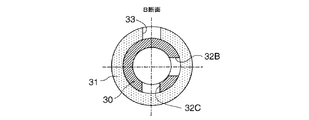
たとえば、図2〜図4の例では、ユニット数が3個の場合で、順に第1、第2、第3ユニットとすると、第1ユニットに対して、第1の開口32が90度間隔で3個(32A、32B、32C)設けられ、第2の開口33が1個設けられており、第2ユニットに対して、第1の開口32が90度間隔で2個(32B、32C)設けられ、第2の開口33が1個設けられており、第3ユニットに対して、第1の開口32(32C)が1個設けられ、第2の開口33が1個設けられている。
第1ユニットのみを発電するユニット4Aとするには、第1の中空軸部材30、第2の中空軸部材31を図2〜図4の位相関係にし、第1ユニット位置で第1の開口32のうち開口32Aが第2の開口33に位相が合致するようにして第1ユニットのみに燃料ガスを供給する。
第1ユニット、第2ユニットのみを発電するユニット4Aとするには、第1の中空軸部材30、第2の中空軸部材31を図2〜図4の位相関係から第1の中空軸部材30が反時計まわりに90度回転した位相とし(第2の中空部材31は回転させない)、第1ユニット位置と第2ユニット位置で第1の開口32のうち開口32Bが第2の開口33に位相が合致するようにして第1ユニットと第2ユニットのみに燃料ガスを供給する。
第1ユニット、第2ユニット、第3ユニットの全てを発電するユニット4Aとするには、第1の中空軸部材30、第2の中空軸部材31を図2〜図4の位相関係から第1の中空軸部材30が反時計まわりに180度回転した位相とし(第2の中空部材31は回転させない)、第1ユニット位置と第2ユニット位置と第3ユニット位置で第1の開口32のうち開口32Cが第2の開口33に位相が合致するようにして第1ユニットと第2ユニットと第3ユニットに燃料ガスを供給する。
開口32、33の位相と数は、図2〜図4の例に限るものではない。
For example, in the example of FIGS. 2 to 4, when the number of units is three and the first, second, and third units are in order, the
In order to use only the first unit as the
In order to obtain the
In order to make all of the first unit, the second unit, and the third unit a
The phase and number of the
燃料ガス供給部29の、回動可能な中空軸部材30は、回動駆動装置34に連結されている。外部回路制御装置23の電子制御装置27は、発電するユニット4Aを選択した時に、該発電するユニット4Aだけに燃料ガスを供給するように、回動駆動装置34による、回動可能な中空軸部材30の回動を制御する。電子制御装置27による接点26の開閉制御と、回動駆動装置34による中空軸部材30の回動制御とは、同時に行われる。
燃料ガス供給部29は、スタック2の各ユニット4の各セル3のセル面内方向中央部に設けられている。セル4の正面視形状は、図示例では円形であるが、正方形、矩形、多角形などの形状であってもよい。
The rotatable
The fuel
接点装置25の接点26の開閉によって、発電するユニット4Aは単独で運転されることもできれば、あるいは複数の発電するユニット4Aの組み合わせで運転されることができる。
複数の発電するユニット4Aの組み合わせで運転される場合は、複数の発電するユニット4Aは、互いに、電気的に直列に接続されてもよいし、あるいは、電気的に並列に接続されてもよい。
直列接続の場合は、スタック2の出力電圧が変わり、出力電流は一定である。並列接続の場合は、スタック2の出力電流が変わり、出力電圧はは一定である。
By opening and closing the
When operated by a combination of a plurality of
In the case of series connection, the output voltage of the
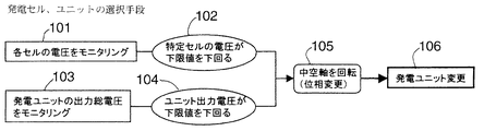
図9は、積層されたユニット4の、発電するユニット4Aを変更する制御を示す。この制御ルーチンは外部回路制御装置23の電子制御装置27にインストールされている。
図9で、ステップ101で各セル3の電圧をモニタリングし、それを電子制御装置27に送信して、ステップ102で特定セル3の電圧が予め設定しておいた下限値を下回るか否かを判定する。下回ればその特定セル3が損傷または不具合を生じたことを意味するので、その特定セル3を含むユニット4を他のスペアユニット4に変えるように、接点装置25の接点26の開閉を制御するとともに、ステップ105で、回動駆動装置34を駆動して回動可能な中空軸部材30を回動し、発電するユニット4Aを正常なスペアユニット4に変更する。
また、ステップ103で、複数の発電するユニット4の出力総電圧をモニタリングし(接点装置25の両端回路の電圧差でモニタリングできる)、それを電子制御装置27に送信して、ステップ104で出力総電圧が予め定めた下限値を下回るか否かを判定する。下回れば何れかのユニット4が損傷または不具合を生じたことを意味するので、ステップ102の判定結果と合わせ考慮してどのユニットが不具合を生じたかを検出し、そのユニットを外すように、ステップ105で、回動駆動装置34を駆動して回動可能な中空軸部材30を回動し、発電するユニット4Aを正常なスペアユニット4に変更する。
FIG. 9 shows control for changing the
In FIG. 9, the voltage of each
Further, in
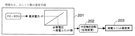
図10は、ユニット4が直列接続されている場合の、発電するユニット4Aの数を変更する制御を示している。この制御ルーチンは外部回路制御装置23の電子制御装置27にインストールされている。
たとえば、車両の場合、外部負荷28は車両の走行に応じて変化する。図10において、ステップ201で、外部負荷、したがって要求電力の変化に応じて、必要電圧、したがって発電するユニット数を求める。発電するユニット数が得られるように、ステップ202で、回動可能な中空軸部材30を回動する。その結果、スタック2の電流をほぼ一定に維持し、発電するユニット数を変えて出力電圧を変えることにより外部負荷の変動に対応することができる。
FIG. 10 shows the control for changing the number of
For example, in the case of a vehicle, the
つぎに、本発明の作用・効果を説明する。
本発明の燃料電池システム1では、セル3を複数積層したユニット4を複数積層してスタック2としたので、スタック型が維持され、コンパクトな燃料電池装置を維持できる。また、外部回路制御装置23と燃料ガス供給部29を設けたので、スタック中の任意の特定セル3が損傷しても、その特定セルを含むユニットを、予めスタック2に組み込んでおいた正常なスペアユニットで置換することができる。これによって、スタック2の寿命をスペアユニットの数倍延ばすことができる。
たとえば、5セルで1ユニットを形成し、44ユニットで1スタックを形成し、4ユニットをスペアユニットとして休止させ、残りの40ユニット、200セルで運転すると、運転中の200セル中の1セルに損傷が生じても、その損傷セルを含むユニットを直列接続から外して、スペアユニットのうちの1ユニットをスタック2に直列接続することにより、正常に運転を継続できる。この場合、スタック2の寿命がスペアユニットの数である4倍延びる。スペアユニット4を設けたことによるスタック2長の延長は1割(40ユニットが44ユニットになる)であるので、とくに問題はない。
Next, functions and effects of the present invention will be described.
In the
For example, 1 unit is formed with 5 cells, 1 stack is formed with 44 units, 4 units are suspended as spare units, and operation is performed with the remaining 40 units and 200 cells. Even if damage occurs, the unit including the damaged cell is removed from the series connection, and one of the spare units is connected to the
また、スタック2に損傷セルが生じていない場合でも、外部負荷28の変動、すなわち要求発電電圧の変動に応じて、外部回路制御装置23と燃料ガス供給部29によって、発電するユニット4Aの数を変化させることにより、各セルをほぼ一定出力運転に維持して外部負荷28の変動に対応することができる。各セルがほぼ一定出力運転の結果、各セル3が損傷を起こしにくくなり、スタック2としての寿命も延びる。
Even when no damaged cell is generated in the
1 燃料電池システム
2 スタック
3 セル
4 ユニット
4A 発電するユニット
5 MEA
6 電解質膜
7 アノード
8 カソード
9、10 拡散層
11 絶縁板
12 セパレータ
13 燃料ガス流路
14 酸化ガス流路
15 冷却水流路
16 入側の燃料ガスマニホールド
17 出側の燃料ガスマニホールド
18 入側の酸化ガスマニホールド
19 出側の酸化ガスマニホールド
20 入側の冷却水マニホールド
21 出側の冷却水マニホールド
22 集電板
23 外部回路制御装置
24 外部回路
25 接点装置
26(26A〜26G) 接点
27 電子制御装置
28 外部負荷
29 燃料ガス供給部
30 第1の中空軸部材
31 第2の中空軸部材
32 第1の開口
33 第2の開口
34 回動駆動装置
1
6 Electrolyte membrane 7 Anode 8
Claims (10)
前記スタックを構成する複数のユニットのうちの任意の1以上のユニットを発電するユニットとして選択し選択された発電するユニットのみを電気的に互いに接続する外部回路制御装置と、
前記スタックを構成する複数のユニットのうち前記選択された1以上の発電するユニットのみに燃料ガスを供給する燃料ガス供給部と、
を有する燃料電池システム。 A stack configured by stacking a plurality of units each including a plurality of single cells;
An external circuit control device that selects only one or more selected power generation units as a power generation unit from among a plurality of units constituting the stack, and electrically connects only the selected power generation units;
A fuel gas supply unit that supplies fuel gas only to the one or more selected power generating units among the plurality of units constituting the stack;
A fuel cell system.
前記スタックを構成する複数のユニットの各ユニットに設けられた外部回路と、
複数の接点を有し前記外部回路と接続された接点装置と、
前記複数のユニットのうちの任意の1以上のユニットを発電するユニットとして選択し選択された発電するユニットのみが電気的に互いに接続されるように前記接点装置の複数の接点の開閉を制御する電子制御装置と、を有する請求項1記載の燃料電池システム。 The external circuit controller is
An external circuit provided in each unit of the plurality of units constituting the stack;
A contact device having a plurality of contacts and connected to the external circuit;
An electronic device that selects any one or more units of the plurality of units as a unit for generating power, and controls opening and closing of the plurality of contacts of the contact device so that only the selected power generating unit is electrically connected to each other. The fuel cell system according to claim 1, further comprising a control device.
該第1、第2の中空軸部材は全ユニットにわたってユニット積層方向に延びており、
該第1、第2の中空軸部材の一方の中空軸部材の外周面は他方の中空軸部材の内周面に摺動可能に接触しており、
該第1、第2の中空軸部材の少なくとも一方の中空軸部材は軸芯まわりに回動可能であり、
該第1、第2の中空軸部材には各ユニットに対応する位置に開口が設けられており、
各ユニットに対応する位置に設けられた前記第1の中空軸部材の開口と前記第2の中空軸部材の開口とは前記発電するユニットのみに燃料ガスを供給するように回転方向位置と数が定められている、請求項1記載の燃料電池システム。 The fuel gas supply unit has first and second hollow shaft members,
The first and second hollow shaft members extend in the unit stacking direction over all units,
The outer peripheral surface of one hollow shaft member of the first and second hollow shaft members is slidably in contact with the inner peripheral surface of the other hollow shaft member,
At least one hollow shaft member of the first and second hollow shaft members is rotatable about an axis;
The first and second hollow shaft members are provided with openings at positions corresponding to the respective units,
The opening of the first hollow shaft member and the opening of the second hollow shaft member provided at a position corresponding to each unit have a rotational direction position and a number so as to supply fuel gas only to the power generating unit. The fuel cell system according to claim 1, wherein the fuel cell system is defined.
Priority Applications (1)
| Application Number | Priority Date | Filing Date | Title |
|---|---|---|---|
| JP2004102573A JP2005293857A (en) | 2004-03-31 | 2004-03-31 | Fuel cell system |
Applications Claiming Priority (1)
| Application Number | Priority Date | Filing Date | Title |
|---|---|---|---|
| JP2004102573A JP2005293857A (en) | 2004-03-31 | 2004-03-31 | Fuel cell system |
Publications (1)
| Publication Number | Publication Date |
|---|---|
| JP2005293857A true JP2005293857A (en) | 2005-10-20 |
Family
ID=35326581
Family Applications (1)
| Application Number | Title | Priority Date | Filing Date |
|---|---|---|---|
| JP2004102573A Pending JP2005293857A (en) | 2004-03-31 | 2004-03-31 | Fuel cell system |
Country Status (1)
| Country | Link |
|---|---|
| JP (1) | JP2005293857A (en) |
Cited By (4)
| Publication number | Priority date | Publication date | Assignee | Title |
|---|---|---|---|---|
| US8304138B2 (en) | 2010-05-26 | 2012-11-06 | Ford Global Technologies, Llc | Fuel cell system and method of use |
| JP2015176737A (en) * | 2014-03-14 | 2015-10-05 | 大阪瓦斯株式会社 | Polymer electrolyte fuel cell |
| JP2017508254A (en) * | 2014-03-12 | 2017-03-23 | セレス インテレクチュアル プロパティー カンパニー リミテッド | Fuel cell stack configuration |
| US11424462B2 (en) | 2010-10-06 | 2022-08-23 | Ford Global Technologies, Llc | Method of operating a fuel cell during a soak time period |
-
2004
- 2004-03-31 JP JP2004102573A patent/JP2005293857A/en active Pending
Cited By (4)
| Publication number | Priority date | Publication date | Assignee | Title |
|---|---|---|---|---|
| US8304138B2 (en) | 2010-05-26 | 2012-11-06 | Ford Global Technologies, Llc | Fuel cell system and method of use |
| US11424462B2 (en) | 2010-10-06 | 2022-08-23 | Ford Global Technologies, Llc | Method of operating a fuel cell during a soak time period |
| JP2017508254A (en) * | 2014-03-12 | 2017-03-23 | セレス インテレクチュアル プロパティー カンパニー リミテッド | Fuel cell stack configuration |
| JP2015176737A (en) * | 2014-03-14 | 2015-10-05 | 大阪瓦斯株式会社 | Polymer electrolyte fuel cell |
Similar Documents
| Publication | Publication Date | Title |
|---|---|---|
| JP4591721B2 (en) | Fuel cell system | |
| JP4492824B2 (en) | Fuel cell system | |
| US20090181269A1 (en) | Fuel cell stack, fuel cell system and method of operating fuel cell system | |
| US6696190B2 (en) | Fuel cell system and method | |
| US7358005B2 (en) | Methods and apparatus for isolating solid oxide fuel cells | |
| US7306873B2 (en) | Method and apparatus for changing the direction of fluid flow in fuel cell flow fields | |
| EP1856754A2 (en) | Air-cooled fuel cell system | |
| US6964824B2 (en) | Fuel cell and method of operating the same | |
| JP3655507B2 (en) | Fuel cell system and electric vehicle equipped with the same | |
| KR20060088932A (en) | Hybrid fuel cell system | |
| KR101461917B1 (en) | Hydrogen and air supply apparatus of fuel cell stack | |
| WO2003096461A1 (en) | Method for detecting undersupply of fuel gas and method for controlling fuel cell | |
| US20090029201A1 (en) | Fuel cell system | |
| JP2005056671A (en) | Fuel cell | |
| JP4173744B2 (en) | Fuel cell unit and operation method thereof | |
| US7595125B2 (en) | Fuel cell stack for vehicle | |
| JP2005293857A (en) | Fuel cell system | |
| JP2007087678A (en) | Fuel cell system | |
| JP2005285402A (en) | Fuel cell stack | |
| KR20070005999A (en) | Stacks and Fuel Cell Devices Comprising the Same | |
| JPH09161819A (en) | Solid polymer electrolyte fuel cell | |
| KR102654843B1 (en) | Air shut off valve apparatus for fuel cell system | |
| JP2006156040A (en) | Fuel cell system | |
| KR102775074B1 (en) | Fuel cell stack and Fuel cell system including the same | |
| KR100906902B1 (en) | Safety system for fuel cell stack and current control method for current supply in case of cell damage |