JP2005293786A - Annealing method of domain wall motion type magneto-optical recording medium and domain wall motion type magneto-optical recording medium subjected to the treatment - Google Patents
Annealing method of domain wall motion type magneto-optical recording medium and domain wall motion type magneto-optical recording medium subjected to the treatment Download PDFInfo
- Publication number
- JP2005293786A JP2005293786A JP2004110850A JP2004110850A JP2005293786A JP 2005293786 A JP2005293786 A JP 2005293786A JP 2004110850 A JP2004110850 A JP 2004110850A JP 2004110850 A JP2004110850 A JP 2004110850A JP 2005293786 A JP2005293786 A JP 2005293786A
- Authority
- JP
- Japan
- Prior art keywords
- recording
- domain wall
- recording medium
- annealing
- power
- Prior art date
- Legal status (The legal status is an assumption and is not a legal conclusion. Google has not performed a legal analysis and makes no representation as to the accuracy of the status listed.)
- Pending
Links
Images




Abstract
【課題】 本発明の目的は、記録前の着磁状態に依存した再生信号への悪影響を排除し、磁壁移動型光磁気記録媒体の繰返し記録耐久性能向上を目指すものである。
【解決手段】 上記の目的は以下の手段によって達成される。
すなわち、磁壁移動型光磁気記録媒体の記録トラック間をアニール処理する方法において、再生信号のパルス幅のデューティーを変化させる記録パワー値が隣接記録トラックをクロスライトする記録パワー値より大きくなるアニールパワーで記録トラック間をアニール処理することによって達成される。
【選択図】 なしAn object of the present invention is to eliminate the adverse effect on a reproduction signal depending on the magnetization state before recording, and to improve the repeated recording durability performance of a domain wall motion type magneto-optical recording medium.
The above object is achieved by the following means.
That is, in the method of annealing between the recording tracks of the domain wall motion type magneto-optical recording medium, the recording power value for changing the duty of the pulse width of the reproduction signal is an annealing power that becomes larger than the recording power value for cross-writing adjacent recording tracks. This is achieved by annealing between the recording tracks.
[Selection figure] None
Description
本発明はレーザー光により記録・再生を行う光磁気記録媒体、更に詳しくは媒体の高密度記録化を可能とする磁壁移動型光磁気記録媒体に関する。 The present invention relates to a magneto-optical recording medium for recording / reproducing with a laser beam, and more particularly to a domain wall motion type magneto-optical recording medium that enables high-density recording of the medium.
情報の書き換え可能な大容量メモリの一つとして、レーザー光を用いて再生、記録を行う光磁気記録媒体が注目されている。再生光学系のレーザー波長λと対物レンズの開口数NAによりビームウェスト径2Wo(2Wo=K・λ/NA)が決まるので、光磁気記録媒体は信号再生時の空間周波数が2NA/λ程度まで検出可能である。しかしながら、光磁気記録媒体のさらなる大容量化への要求は高まる一方である。この要求を満たす目的で、すなわち、光磁気記録媒体の記録密度を波長λと開口数NAで決まる回折限界を超える密度にまで高めるために、記録媒体の構成や読み取り方法を工夫し、記録密度を改善する技術が開発されている。 As one of large capacity rewritable memories, a magneto-optical recording medium that reproduces and records using a laser beam has attracted attention. Since the beam waist diameter 2Wo (2Wo = K · λ / NA) is determined by the laser wavelength λ of the reproducing optical system and the numerical aperture NA of the objective lens, the magneto-optical recording medium detects a spatial frequency up to about 2NA / λ during signal reproduction. Is possible. However, the demand for further increasing the capacity of the magneto-optical recording medium is increasing. In order to satisfy this requirement, that is, in order to increase the recording density of the magneto-optical recording medium to a density exceeding the diffraction limit determined by the wavelength λ and the numerical aperture NA, the constitution of the recording medium and the reading method are devised, and the recording density is increased. Improvement techniques are being developed.
光学的な回折限界を超えた微小記録磁区長まで記録密度を上げた光磁気記録媒体として、例えば、特開平3−93058号公報や特開平6−124500号公報には、磁気的に結合される再生層と記録層とを有してなる多層膜の記録層に信号記録を行うとともに、再生層の磁化の向きを揃えた後(特開平6−124500号の磁化方向は面内)、レーザー光を照射して加熱し、再生層の昇温領域に記録層に記録された信号を転写しながら読み取る信号再生方法が提案されている。 As a magneto-optical recording medium in which the recording density is increased to a minute recording magnetic domain length exceeding the optical diffraction limit, for example, Japanese Patent Application Laid-Open No. 3-93058 and Japanese Patent Application Laid-Open No. 6-124500 are magnetically coupled. Signal recording is performed on a multi-layered recording layer having a reproducing layer and a recording layer, and the direction of magnetization of the reproducing layer is aligned (the magnetization direction of JP-A-6-124500 is in-plane), and then laser light A signal reproduction method has been proposed in which a signal recorded on a recording layer is transferred to a temperature rising region of the reproduction layer and read while being heated.
この方法によれば、再生用のレーザーのスポット径に対して、このレーザーによって加熱された転写温度に達し信号が検出される領域(アパーチャー)はより小さな領域に限定できるため、再生時の符号間干渉を減少させ、光学的な検出限界λ/2NA以下のピット周期の信号が再生可能となる。以上の再生方法はMSR(a magnetically induced superresolution readout method)再生方式と呼ばれている。 According to this method, the area (aperture) in which the signal is detected by reaching the transfer temperature heated by this laser can be limited to a smaller area with respect to the spot diameter of the laser for reproduction. Interference is reduced, and a signal having a pit period less than or equal to the optical detection limit λ / 2NA can be reproduced. The above reproduction method is called an MSR (a magnetically induced superresolution readout method) reproduction method.
上記、MSR再生方式では、再生用のレーザーのスポット径に対して、有効に使用される信号検出領域が小さくなるため、再生信号振幅が大幅に低下し、十分な再生出力が得られない欠点を有している。 In the above-mentioned MSR reproduction method, since the signal detection area that is effectively used becomes smaller with respect to the spot diameter of the laser for reproduction, the reproduction signal amplitude is greatly reduced, and sufficient reproduction output cannot be obtained. Have.
上記MSR再生方式の欠点を補った、光磁気記録媒体の再生方法及び再生装置として、特開平6−290496号公報に、交換結合多層膜からなる光磁気記録媒体により、再生信号振幅を低下させることなく光学的な検出限界以下の周期の信号が高速で再生可能となり、記録密度並びに転送速度を大幅に向上できる光磁気記録媒体、再生方法及び再生装置が提案されている。この再生方法は、付属の加熱装置により再生記録マークに温度分布をもたせ、この温度分布と再生記録マーク中の磁壁エネルギーの温度依存性とにより、図7に示すように、磁壁に再生光スポット(74)内へ移動する圧力が誘発される。第二の磁性層(732)のキュリー温度近傍まで再生記録マークが昇温された場合、第一の磁性層(731)と他の磁性層との交換結合が切断され、記録トラックの両サイドの磁気的結合分断領域の存在により、第一の磁性層(731)の磁壁(72)が瞬間的に再生光スポット(74)内へ移動する。そして、その結果、再生光スポット(74)内の原子スピン(71)の向きが反転して全て一方向にそろい、再生記録マークが拡大される。従って、再生信号振幅は記録されている磁壁の間隔(すなわち記録マーク長)によらず、常に一定かつ最大の振幅になり、光学的な回折限界に起因した波形干渉等の問題から完全に解放される。以上の再生方法はDWDD(domain wall displacement detection)再生方式と呼ばれている。 As a reproducing method and reproducing apparatus for a magneto-optical recording medium that compensates for the disadvantages of the above-mentioned MSR reproducing method, Japanese Patent Application Laid-Open No. 6-290496 discloses that a reproducing signal amplitude is reduced by using a magneto-optical recording medium comprising an exchange coupling multilayer film. In addition, a magneto-optical recording medium, a reproducing method, and a reproducing apparatus have been proposed in which a signal having a period equal to or less than the optical detection limit can be reproduced at high speed, and the recording density and transfer speed can be greatly improved. In this reproducing method, a reproduction recording mark is provided with a temperature distribution by an attached heating device, and a reproduction light spot (on the domain wall is shown in FIG. 7 based on this temperature distribution and the temperature dependence of the domain wall energy in the reproduction recording mark. 74) A pressure to move in is induced. When the temperature of the reproduction recording mark is raised to near the Curie temperature of the second magnetic layer (732), the exchange coupling between the first magnetic layer (731) and the other magnetic layer is cut, and both sides of the recording track are cut. Due to the presence of the magnetic coupling division region, the domain wall (72) of the first magnetic layer (731) instantaneously moves into the reproduction light spot (74). As a result, the directions of the atomic spins (71) in the reproduction light spot (74) are reversed and aligned in one direction, and the reproduction recording mark is enlarged. Therefore, the playback signal amplitude is always constant and maximum regardless of the recorded domain wall interval (ie, recording mark length), and is completely free from problems such as waveform interference due to optical diffraction limits. The The above reproduction method is called a DWDD (domain wall displacement detection) reproduction method.
DWDD再生方式において、第一の磁性層上に形成された第三の磁性層からの転写磁区の磁壁を再生光スポット内へ移動させ、磁区の面積を拡大させるには、記録トラックの両サイドに磁気的結合分断領域を形成することが好ましい。この磁気的結合分断領域は少なくとも、第一の磁性層上に形成されていなければならない。また、この磁気的結合分断領域は、磁性を示さない、あるいは、面内磁化膜であることが好ましい。このようにすることにより磁区の拡大に際し、磁気的結合分断領域には磁壁が存在しない、あるいは、存在してもエネルギーの小さい磁壁が形成されるだけなので、スムーズな磁壁の移動を可能にし、記録再生信号の品位が向上する。 In the DWDD reproduction method, the domain wall of the transfer magnetic domain from the third magnetic layer formed on the first magnetic layer is moved into the reproduction light spot, and the area of the magnetic domain is expanded on both sides of the recording track. It is preferable to form a magnetic coupling division region. This magnetic coupling breaking region must be formed at least on the first magnetic layer. Moreover, it is preferable that this magnetic coupling division area does not show magnetism, or is an in-plane magnetization film. In this way, when the magnetic domain is expanded, there is no domain wall in the magnetic coupling break region, or even if it exists, only a domain wall with low energy is formed, enabling smooth domain wall movement and recording. The quality of the playback signal is improved.
磁気的結合分断領域を形成する方法として、記録トラックの両サイドの磁性膜を高いパワーでレーザー光を照射して、その磁性膜の磁気的性質を変質させて行う方法、いわゆる、レーザーアニール処理法がある。 As a method of forming the magnetically-coupled region, a method in which the magnetic film on both sides of the recording track is irradiated with laser light with high power and the magnetic properties of the magnetic film are altered, so-called laser annealing method There is.
レーザーアニール処理法では、再生信号品位が最良となるようにアニール条件を求め、その条件によりディスク前面にわたってアニール処理を行って磁気的結合分断領域の形成を行う。ここでのアニール条件は、アニール時のレーザーパワー、線速度、トラッキングのオフセット量、フォーカスのオフセット量、チルト量などが挙げられる。
DWDD再生方式は、原理的に、再生信号振幅は記録されている磁壁の間隔(すなわち記録マーク長)によらず、常に一定かつ最大の振幅になり、光学的な回折限界に起因した波形干渉等の問題から完全に解放されると考えられている。 In principle, the DWDD playback system has a playback signal amplitude that is always constant and maximum regardless of the interval between recorded domain walls (that is, the recording mark length), and waveform interference caused by an optical diffraction limit. It is believed that they will be completely free from problems.
しかしながら、再生信号品位が最良となるようにアニール条件を求め、その条件によりディスク前面にわたってアニール処理を行って磁気的結合分断領域の形成を行った磁壁移動型光磁気記録媒体(以下、DWDDメディアと略す場合もある)でもディスクによっては隣のトラックにはみ出して記録してしまうクロスライトする記録パワー以下のパワーでドライブを動作させる実使用環境化において、記録再生信号特性が劣化する媒体が生じるという問題が発生する。 However, an annealing condition is obtained so that the reproduction signal quality is the best, and a magnetic domain displacement type magneto-optical recording medium (hereinafter referred to as a DWDD medium) in which a magnetic coupling separation region is formed by performing an annealing process on the disk front surface under the condition. However, depending on the disc, there is a problem that a medium with a deteriorated recording / reproducing signal characteristic is generated in an actual use environment in which the drive is operated with a power lower than the recording power for cross-writing which is recorded on the adjacent track. Will occur.
これらのディスクの中で特性の悪かったディスクを詳細に調査した結果、図5のような現象を示すことで特性が劣化することが確認された。 As a result of detailed investigation of the discs having poor characteristics among these discs, it was confirmed that the characteristics were deteriorated by showing the phenomenon as shown in FIG.
図5は、トーン信号を記録再生したときの再生信号波形におけるパルス幅PW、及び、ジッターσの記録パワー依存性を示した模式説明図である。 FIG. 5 is a schematic explanatory diagram showing the recording power dependence of the pulse width PW and jitter σ in the reproduced signal waveform when the tone signal is recorded and reproduced.
ここでのパルス幅、及び、ジッターは、再生波形の立ち上がりから次の立下りまでの間隔(パルス幅)を複数波形について測定し、統計的に処理して求められた平均パルス幅、及び、パルス幅ジッターのことをさしている。また、これらの特性は、記録前の初期状態として記録トラックとその両側の隣接トラックを同一極性に一方向に着磁した状態にしてから、記録・再生して求めた時の特性を示している。 The pulse width and jitter here are the average pulse width and pulse obtained by measuring the interval (pulse width) from the rising edge of the reproduced waveform to the next falling edge (pulse width) and statistically processing them. It refers to width jitter. These characteristics are obtained when recording and reproduction are performed after the recording track and adjacent tracks on both sides thereof are magnetized in one direction with the same polarity as an initial state before recording. .
尚、ここで、再生される再生信号波形の立ち上がりから立ち上がり(または、立下りから立下り)までの間隔(いわゆる1周期分の間隔)に変化は観測されないので、1周期分の間隔に対するパルス幅の割合、すなわち、デューティーが変化したといえる。 Here, since no change is observed in the interval (so-called one cycle interval) from the rise to the rise (or the fall to the fall) of the reproduced signal waveform to be reproduced, the pulse width with respect to the interval of one cycle It can be said that the ratio, that is, the duty has changed.
図5によれば、パルス幅は、記録パワーが低いP3では、パルス幅PW1を示し、記録パワーが高いP4ではパルス幅PW2を示す。 According to FIG. 5, the pulse width indicates the pulse width PW1 at P3 where the recording power is low, and indicates the pulse width PW2 at P4 where the recording power is high.
記録パワーP1では、平均パルス幅PW1の再生信号波形とPW2の再生信号波形が混在しており、その結果、平均パルス幅としておよそ(PW1+PW2)/2を示し、ジッターは悪化してしまう。 At the recording power P1, the reproduction signal waveform having the average pulse width PW1 and the reproduction signal waveform having the PW2 are mixed, and as a result, the average pulse width is approximately (PW1 + PW2) / 2, and the jitter is deteriorated.
また、このようなDWDDメディアは、記録パワーP4で記録した後に、記録パワーP3でオーバーライトした場合、パルス幅はPW1ではなく、PW2を示し、記録パワーがP1以下のP3で記録した後に、再度記録パワーP3でオーバーライトした場合のパルス幅は、PW1を示す。 Further, when such DWDD media is recorded with the recording power P4 and then overwritten with the recording power P3, the pulse width indicates not PW1, but PW2, and the recording power is recorded with P3 equal to or lower than P1, and then again. The pulse width when overwritten with the recording power P3 indicates PW1.
同じ記録パワーP3でオーバーライトして、異なるパルス幅が形成されるということは、最初にP3の記録パワーで記録してオーバーライトした状態と最初にP4の記録パワーで記録してオーバーライトした状態とでは、磁気的結合分断領域を含む記録トラックの着磁状態が異なるということを示している。この結果、同じ記録パワーP3でオーバーライトしたとしても、この2状態では異なるパルス幅を示すということである。また、図5では、PW1<PW2となっているが、記録前の着磁方向を逆極性にすればPW1>PW2の関係となる。 Overwriting with the same recording power P3 to form different pulse widths means that the recording was first performed with the recording power of P3 and overwritten, and the first recording was performed with the recording power of P4 and overwritten. This indicates that the magnetization state of the recording track including the magnetic coupling break region is different. As a result, even if overwriting is performed with the same recording power P3, the two states show different pulse widths. Further, in FIG. 5, PW1 <PW2, but if the magnetization direction before recording is reversed, the relationship PW1> PW2 is established.
一方、実際にDWDDメディアを使用する時には、隣接トラックには情報ビットを担う複数種類の長さからなる記録マークが形成されている場合が多い。このとき、記録トラックと隣接トラックとの間の着磁の関係は、図6に示すようにパターン1〜8までの8種類となる。この8種類の関係が、複数種類の長さの記録マークにより、さまざまな位置関係で配置されている。
On the other hand, when actually using DWDD media, there are many cases where recording marks having a plurality of types of lengths carrying information bits are formed on adjacent tracks. At this time, the relationship of magnetization between the recording track and the adjacent track is eight types of
このような磁化状態の中でも、上述したような特性を示すDWDDメディアは、図5の記録パワーP3で用いる場合は、複数回の記録を繰り返しても一定の特性が得られる。しかし、図5の記録パワーP4で記録を行った場合、その後、記録パワーP3で記録しなおしても、記録パワーP3で記録した時の特性が得られない。これは、図6のパターン1〜8に応じてPW2の幅が変化するということが起因していることが分かった。
Even in such a magnetized state, when the DWDD medium showing the above-described characteristics is used at the recording power P3 in FIG. 5, a certain characteristic can be obtained even if recording is repeated a plurality of times. However, when recording is performed with the recording power P4 in FIG. 5, the characteristics when recording with the recording power P3 cannot be obtained even if recording is performed again with the recording power P3. This was found to be due to the fact that the width of PW2 changes according to
このような再生信号の特性変化は信号処理では補償しきれず、DWDDメディアの信頼性を著しく低下させるものであった。 Such a change in the characteristics of the reproduced signal cannot be compensated for by signal processing, and the reliability of the DWDD media is remarkably lowered.
本発明の目的は、上記のような問題点に鑑み、記録前の着磁状態に依存した再生信号への悪影響を排除し、磁壁移動型光磁気記録媒体の繰返し記録耐久性能向上を目指すものである。 In view of the above problems, the object of the present invention is to eliminate the adverse effects on the reproduction signal depending on the magnetization state before recording, and to improve the repeated recording durability performance of the domain wall motion type magneto-optical recording medium. is there.
前記の目的は以下の手段によって達成される。 The above object is achieved by the following means.
すなわち、磁壁移動型光磁気記録媒体の記録トラック間をアニール処理する方法において、再生信号のパルス幅のデューティーを変化させる記録パワー値が隣接記録トラックをクロスライトする記録パワー値より大きくなるアニールパワーで記録トラック間をアニール処理することによって達成される。また、その様なアニール処理を施された磁壁移動型光磁気記録媒体によって達成される。 That is, in the method of annealing between the recording tracks of the domain wall motion type magneto-optical recording medium, the recording power value for changing the duty of the pulse width of the reproduction signal is an annealing power that becomes larger than the recording power value for cross-writing adjacent recording tracks. This is achieved by annealing between the recording tracks. Further, this is achieved by the domain wall motion type magneto-optical recording medium subjected to such annealing treatment.
本発明の磁壁移動型光磁気記録媒体を用いることにより、少なくともクロスライトする記録パワー以下のパワーでドライブを動作させる実使用環境化においては、良好な書換え記録耐久性が実現できる。 By using the domain wall motion type magneto-optical recording medium of the present invention, good rewritable recording durability can be realized in an actual use environment where the drive is operated at least at a power equal to or lower than the recording power for cross writing.
本発明は、図1に示すように、再生信号のパルス幅のデューティーが変化する記録パワーをP1、クロスライトする記録パワーをP2としたときに、P2<P1となる磁壁移動型光磁気記録媒体を提案するものである。 As shown in FIG. 1, the present invention provides a domain wall motion magneto-optical recording medium in which P2 <P1, where P1 is the recording power at which the duty of the pulse width of the reproduction signal changes, and P2 is the recording power for cross writing. This is a proposal.
ドライブ側で用いるパワーは、実使用上、隣接トラックにクロスライトしてデータを破壊してしまう記録パワーP2よりも小さいパワー範囲内で動作させている。従って、図1に示すように、記録パワーP1においてパルス幅が急激に変化する現象が確認されたとしても、実使用ではP2以下の記録パワーで用いるので、繰返し記録を行っても初期の特性が維持される。 In actual use, the power used on the drive side is operated within a power range smaller than the recording power P2 that cross-writes adjacent tracks and destroys data. Therefore, as shown in FIG. 1, even if a phenomenon in which the pulse width changes suddenly at the recording power P1 is confirmed, since the recording power is used at a recording power of P2 or less in actual use, the initial characteristics can be obtained even when repeated recording is performed. Maintained.
本発明の具体的な手段としては、磁気的結合分断領域の形成を行うレーザーアニール処理を、ハイパワーで行うことが挙げられる。つまり、記録パワーP1及びP2はアニールパワーに依存性があり、アニールパワーの適切な設定により上述のP2<P1を示す磁壁移動型光磁気記録媒体を比較的容易に得ることができる。 As a specific means of the present invention, a laser annealing process for forming a magnetic coupling break region is performed with high power. That is, the recording powers P1 and P2 depend on the annealing power, and the domain wall motion magneto-optical recording medium satisfying P2 <P1 described above can be obtained relatively easily by appropriately setting the annealing power.
より具体的な説明を以下に記す。 A more specific explanation is given below.
図9は、再生信号のパルス幅のデューティーが変化する記録パワーP1、及び、クロスライトする記録パワーP2のレーザーアニール処理におけるアニールパワー依存性を示す。 FIG. 9 shows the annealing power dependence in the laser annealing process of the recording power P1 in which the duty of the pulse width of the reproduction signal changes and the recording power P2 to be cross-written.
なお、記録パワーP1は、隣接する記録トラックを含め記録トラックが初期化された状態で、記録パワーを変えながらトーン信号を記録し、その後、そのトーン信号を再生し、再生されたトーン信号のパルス幅の変化を検知することにより求める。このとき、パルス幅が変化する記録パワーが再生信号のパルス幅のデューティーが変化する記録パワーP1である。次に、記録パワーP2の求め方は、所定の記録トラックの両脇の記録トラックに一定記録パワーで信号を記録し、次に、中央の記録トラックに記録パワーを変えながら信号を記録する。次に、両脇の記録トラックのどちらか一方の記録トラックの記録信号を再生し、再生信号特性(ジッタ、エラーレートなど)が所定レベルに対し悪化する記録パワーをクロスライトする記録パワーP2として求める。 The recording power P1 is recorded in a state where the recording track including the adjacent recording track is initialized, and the tone signal is recorded while changing the recording power, and then the tone signal is reproduced, and the pulse of the reproduced tone signal is reproduced. It is obtained by detecting the change in width. At this time, the recording power at which the pulse width changes is the recording power P1 at which the duty of the pulse width of the reproduction signal changes. Next, the recording power P2 is obtained by recording a signal with a constant recording power on the recording tracks on both sides of a predetermined recording track, and then recording the signal while changing the recording power on the central recording track. Next, the recording signal of one of the recording tracks on both sides is reproduced, and the recording power at which the reproduction signal characteristics (jitter, error rate, etc.) deteriorate with respect to a predetermined level is obtained as the recording power P2 for cross writing. .
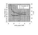
以上のようにして記録パワーP1、P2が各アニールパワーに対して求められ、図9が得られる。図9において、アニールパワーの増加にともないP1もP2も増加し、アニールパワーがおよそ6.5mWよりも小さい領域ではP2>P1、アニールパワーがおよそ6.5mWよりも大きい領域ではP2<P1となっていることが分かる。また、アニールパワー7.0mWではP1のプロットが示されていないが、これは、このアニールパワーのときに再生信号のパルス幅のデューティーが変化する現象が現れていないことを示す。本発明では、図9のようなアニールパワー依存性を有する磁壁移動型光磁気記録媒体において、P2<P1となるアニールパワー(図9においては、およそ6.6mW以上のアニールパワー)を選択し、磁壁移動型光磁気記録媒体の記録トラック間をレーザーアニール処理している。これにより、良好な書換え記録耐久性が実現できるのである。 As described above, the recording powers P1 and P2 are obtained for each annealing power, and FIG. 9 is obtained. In FIG. 9, both P1 and P2 increase as the annealing power increases, and P2> P1 in the region where the annealing power is smaller than about 6.5 mW, and P2 <P1 in the region where the annealing power is larger than about 6.5 mW. I understand that In addition, although the plot of P1 is not shown at the annealing power of 7.0 mW, this indicates that the phenomenon that the duty of the pulse width of the reproduction signal changes does not appear at this annealing power. In the present invention, in the domain wall motion type magneto-optical recording medium having the annealing power dependency as shown in FIG. 9, an annealing power satisfying P2 <P1 (in FIG. 9, an annealing power of about 6.6 mW or more) is selected. Laser annealing is performed between the recording tracks of the domain wall motion type magneto-optical recording medium. Thereby, good rewrite recording durability can be realized.
(実施例1)
本実施例における光磁気記録媒体の基本構成図を図8に示す。
(Example 1)
FIG. 8 shows a basic configuration diagram of the magneto-optical recording medium in this embodiment.
本実施例で使用した基板(81)は、ポリカーボネート(PC)を用いて射出成形により作製した。基板(81)は、トラックピッチ0.55μm、グルーブ幅0.42μm、溝深さ0.03μmのグルーブ記録用基板である。グルーブ幅は溝深さの半値幅で規定している。また、本実施例では、溝を形成しているランド上にサーボ用のピットが形成されており、このサーボピットを利用してサンプルサーボによりトラッキング動作を行っている。 The substrate (81) used in this example was produced by injection molding using polycarbonate (PC). The substrate (81) is a groove recording substrate having a track pitch of 0.55 μm, a groove width of 0.42 μm, and a groove depth of 0.03 μm. The groove width is defined by the half width of the groove depth. Further, in this embodiment, servo pits are formed on lands forming grooves, and tracking operation is performed by sample servo using the servo pits.
本実施例では射出成形基板にポリカーボネート(PC)を用いたが、ポリメチルメタクリレート(PMMA)、アモルファスポリオレフィン(APO)等を成形材料として用いてもよい。また、紫外線硬化樹脂による、いわゆる2P成形基板を使用することもできる。また、本実施例では、グルーブ記録用基板を用いたが、当然、ランド記録用基板でも、ランド・グルーブ記録用基板でも使用可能である。 In this embodiment, polycarbonate (PC) is used for the injection-molded substrate, but polymethyl methacrylate (PMMA), amorphous polyolefin (APO) or the like may be used as a molding material. Also, a so-called 2P molded substrate made of an ultraviolet curable resin can be used. In this embodiment, the groove recording substrate is used, but it is naturally possible to use either a land recording substrate or a land / groove recording substrate.
以上のようにして作製した基板上に記録膜をスパッタ法により成膜した。以下に具体的な各記録膜の例を示すが、本発明はその主旨を逸脱しない限り、以下の実施例に限定されるものではない。 A recording film was formed by sputtering on the substrate manufactured as described above. Specific examples of each recording film are shown below, but the present invention is not limited to the following examples unless departing from the gist thereof.
記録膜としては、基板上に第一の誘電体層(82)(SiN)、第一の磁性層(831)(磁壁移動層、GdFeCo、膜厚20nm)、第二の磁性層(832)(磁壁移動補助層、GdFe、膜厚20nm)、第三の磁性層(833)(制御層、TbFeCo、膜厚10nm)、第四の磁性層(834)(スイッチング層、TbFe、膜厚15nm)、第五の磁性層(835)(記録層、TbFeCo、膜厚60nm)、第二の誘電体層(84)(SiN)が順次積層されている。各誘電体層としては、SiNの他に、例えば、AlN、SiO2、SiO、ZnS、MgF2などの透明誘電材料が使用できる。また、第一の磁性層(831)、第二の磁性層(832)、第三の磁性層(833)、第四の磁性層(834)、第五の磁性層(835)としては、上記磁性材料を含む種々の磁性材料によって構成することが考えられるが、例えば、Pr、Nd、Sm、Gd、Tb、Dy、Hoなどの希土類金属元素の一種類あるいは二種類以上が10〜40原子%と、Fe、Co、Niなどの遷移金属の一種類あるいは二種類以上が60〜90原子%で構成される希土類・遷移金属非晶質合金によって構成し得る。
As the recording film, a first dielectric layer (82) (SiN), a first magnetic layer (831) (domain wall moving layer, GdFeCo, film thickness 20 nm), a second magnetic layer (832) (on a substrate) Domain wall motion auxiliary layer, GdFe, film thickness 20 nm), third magnetic layer (833) (control layer, TbFeCo,
また、耐食性向上などのために、Cr、Mn、Cu、Ti、Al、Si、Pt、Inなどの元素を少量添加してもよい。 In order to improve corrosion resistance, a small amount of elements such as Cr, Mn, Cu, Ti, Al, Si, Pt, and In may be added.
また、各磁性層の詳細な説明を以下に記す。磁壁移動型光磁気記録媒体の基本的な層構成は、第一の磁性層(831)、第四の磁性層(834)、第五の磁性層(835)であり、この三つの磁性層により、磁壁移動・磁区拡大再生動作が実現できる光磁気記録媒体を作製することが可能となる。このとき、第一の磁性層(831)は少なくとも再生ビームスポット内の記録情報検出領域内では第五の磁性層(835)に比べ相対的に磁壁抗磁力が小さく磁壁移動度が大きな垂直磁化膜からなっている。また、第四の磁性層(834)は、全磁性層の中で最もキュリー温度の低い磁性層からなり、垂直磁気異方性、磁壁抗磁力が大きく、安定に磁化状態を転写できるものが望ましい。第五の磁性層(835)は垂直磁化膜からなっており、垂直磁気異方性、磁壁抗磁力が大きく、安定に記録磁区が保持できるものが望ましい。 A detailed description of each magnetic layer will be given below. The basic layer structure of the domain wall motion type magneto-optical recording medium is a first magnetic layer (831), a fourth magnetic layer (834), and a fifth magnetic layer (835). Thus, it becomes possible to produce a magneto-optical recording medium capable of realizing the domain wall movement / domain expansion reproduction operation. At this time, the first magnetic layer (831) is a perpendicular magnetization film having a relatively small domain wall coercive force and a large domain wall mobility compared to the fifth magnetic layer (835) in at least the recorded information detection region in the reproduction beam spot. It is made up of. The fourth magnetic layer (834) is preferably composed of a magnetic layer having the lowest Curie temperature among all the magnetic layers, and has a large perpendicular magnetic anisotropy and domain wall coercive force so that the magnetization state can be transferred stably. . The fifth magnetic layer (835) is made of a perpendicularly magnetized film, and preferably has a large perpendicular magnetic anisotropy and domain wall coercive force and can stably maintain a recording magnetic domain.
さらに、他の磁性層について説明すると、第二の磁性層(832)は再生特性を向上させるために設けており、第一の磁性層(831)のキュリー温度よりは低く、また、少なくとも再生ビームスポット内の記録情報検出領域内では第五の磁性層(835)に比べ相対的に磁壁抗磁力が小さく磁壁移動度が大きな垂直磁化膜からなっている。第三の磁性層(833)は、再生ビームスポット後方端部での第五の磁性層(835)から第一の磁性層(831)へ再転写された磁区の磁壁の移動により引き起こされる、再生信号への重畳信号、いわゆるゴースト信号を抑制するための磁性層である。この第三の磁性層(833)は、垂直磁気異方性が大きく、第一の磁性層(831)よりも磁壁抗磁力が大きい磁性層を用いるのが望ましい。 Further, the other magnetic layer will be described. The second magnetic layer (832) is provided to improve the reproduction characteristics, is lower than the Curie temperature of the first magnetic layer (831), and at least the reproduction beam. In the recorded information detection area in the spot, the magnetic domain coercive force is relatively small compared to the fifth magnetic layer (835), and the perpendicular magnetic film has a large domain wall mobility. The third magnetic layer (833) is caused by the movement of the domain wall of the magnetic domain retransferred from the fifth magnetic layer (835) to the first magnetic layer (831) at the rear end of the reproduction beam spot. This is a magnetic layer for suppressing a superimposed signal, that is, a so-called ghost signal. As the third magnetic layer (833), it is desirable to use a magnetic layer having a large perpendicular magnetic anisotropy and a magnetic domain coercive force larger than that of the first magnetic layer (831).
本実施例では、各磁性層のキュリー温度として、第一の磁性層(831)は300℃程度、第二の磁性層(832)は220℃程度、第三の磁性層(833)は190℃程度、第四の磁性層(834)は170℃程度、第五の磁性層(835)は330℃程度であった。 In this example, the Curie temperatures of the respective magnetic layers are as follows: the first magnetic layer (831) is about 300 ° C., the second magnetic layer (832) is about 220 ° C., and the third magnetic layer (833) is 190 ° C. The fourth magnetic layer (834) was about 170 ° C., and the fifth magnetic layer (835) was about 330 ° C.
以上のようにして作製した光磁気記録媒体のランドに、ディスク回転速度4.5m/s、図9に基づくアニールパワー6.6mWでλ=405nm、NA=0.85の光学系を用いたレーザー光を照射するレーザーアニール処理を施した。このときのアニ−ル処理は、レーザー光を膜面側から照射して行っている。この処理により、各ランドでランド中心に向かって垂直磁気異方性から膜面内磁気異方性へと磁気異方性が変質しており、アニールパワーが高いほどランド上の磁性は膜面内磁気異方性を強める。また、本実施例では、上述したように、膜面側からレーザー光を照射してアニール処理を行ったが、基板側からレーザー光を照射してアニール処理を施しても、膜面側、及び、基板側の両面からレーザー光を照射してアニール処理を施しても、同様に本発明の効果を得ることができる。 A laser using an optical system of λ = 405 nm and NA = 0.85 at a disk rotational speed of 4.5 m / s, an annealing power of 6.6 mW based on FIG. Laser annealing treatment was applied to irradiate light. The annealing process at this time is performed by irradiating laser light from the film surface side. As a result of this treatment, the magnetic anisotropy of each land changes from perpendicular magnetic anisotropy to in-film magnetic anisotropy toward the center of the land. Increase magnetic anisotropy. Further, in this example, as described above, the annealing process was performed by irradiating the laser beam from the film surface side, but even if the annealing process was performed by irradiating the laser beam from the substrate side, The effects of the present invention can be obtained in the same manner even when annealing is performed by irradiating laser light from both sides on the substrate side.
以上のようにして作製したアニールによる磁壁移動型光磁気記録媒体に対し着磁装置を用いて、全周にわたって一方向に磁化する処理を行った。このときの着磁は、外部磁界Hd=1KOeを垂直方向にDC的に印加した上で、波長λ780nm、スポット径50μm(90トラック分に相当)のレーザー光を照射して行った。このとき、着磁パワー10mW、ディスク回転速度LV=6m/sであった。当然、1トラックずつ光スポットを走査して、外部磁界により一方向に着磁しても本発明の効果は得られる。 The magnetic domain wall motion type magneto-optical recording medium produced by annealing as described above was magnetized in one direction over the entire circumference using a magnetizing device. Magnetization at this time was performed by applying a laser beam having a wavelength of λ780 nm and a spot diameter of 50 μm (corresponding to 90 tracks) after applying an external magnetic field Hd = 1 KOe in a DC direction. At this time, the magnetizing power was 10 mW, and the disk rotation speed LV was 6 m / s. Naturally, the effect of the present invention can be obtained even if the light spot is scanned one track at a time and magnetized in one direction by an external magnetic field.
以上のようにして作製した磁壁移動型光磁気記録媒体を用いて、data−to−dataのトーンジッターσ、及び、再生信号波形のパルス幅PWの記録パワー依存性の測定を行った。パルス幅PWは、80nm/bit、(1,7)−RLLにおける最短マーク長のトーン記録再生信号の波形の立ち上がりから次の立ち下りまでの間隔を、最短マーク長の2倍の長さを100%とした場合の割合として求めた。ディスク回転速度2.4m/s、磁界強度300Oe、記録周波数11.25MHz、光学系λ=650nm、NA=0.6で、マーク長0.107μm(80nm/bit、(1,7)−RLLの最短マーク長に相当する)のトーン信号を記録した。情報の再生は、記録と同一の光学系で、ディスク回転速度2.4m/s、レーザーパワー2.4mWで行った。 Using the domain wall motion type magneto-optical recording medium manufactured as described above, the recording power dependence of the data-to-data tone jitter σ and the pulse width PW of the reproduced signal waveform was measured. The pulse width PW is 80 nm / bit, and the interval from the rising edge of the waveform of the tone recording / reproducing signal having the shortest mark length in (1,7) -RLL to the next falling edge is 100 times the shortest mark length. % As a percentage. Disk rotation speed 2.4 m / s, magnetic field strength 300 Oe, recording frequency 11.25 MHz, optical system λ = 650 nm, NA = 0.6, mark length 0.107 μm (80 nm / bit, (1,7) -RLL The tone signal (corresponding to the shortest mark length) was recorded. Information was reproduced using the same optical system as that used for recording at a disc rotational speed of 2.4 m / s and a laser power of 2.4 mW.
以上のようにして得られた記録パワー依存性が図2であり、クロスライトする記録パワー(7.4mW)以下ではパルス幅のデューティーの急激な変化は観測されず、ジッターもこのパワー範囲内では局所的な悪化は見られなかった。このとき、クロスライトが生じる記録パワー7.4mWは、デューティー変化をもたらす記録パワー(7.6mW)以下のパワーである。 The recording power dependency obtained as described above is shown in FIG. 2. A sudden change in the duty of the pulse width is not observed below the recording power (7.4 mW) for cross writing, and the jitter is also within this power range. There was no local deterioration. At this time, the recording power of 7.4 mW at which cross writing occurs is a power equal to or lower than the recording power (7.6 mW) that causes the duty change.
以上の光磁気記録媒体において、記録しようとするNトラックの隣接トラック((N±1)トラック)に80nm/bit、(1,7)−RLLのランダムパターンの記録マークを形成し、その後、Nトラックに80nm/bitのランダムパターンを記録しbERの測定を行った。記録パワーは、bERが最も良好な値を示すときの記録パワー6.6mWである。このとき、bER=3.0×10-5であった。次に、Nトラックにクロスライトが生じる記録パワー7.4mWで10万回オーバーライトし、その後、記録パワー6.6mWでオーバーライトしてbERを測定した。オーバーライト後ではbER=3.3×10-5で、オーバーライト前後で特性は変わらなかった。すなわち、クロスライトするような記録パワーで記録しても、記録パワー6.6mWで記録し直せば元の特性が得られ、実使用上、繰り返し記録耐久的に問題はなかった。
(実施例2)
アニールパワー6.8mWでアニール処理を行ったこと以外は、実施例1と同様にして媒体の作製、及び、測定を行った。
In the above magneto-optical recording medium, a recording mark having a random pattern of 80 nm / bit, (1, 7) -RLL is formed on an adjacent track ((N ± 1) track) of the N track to be recorded. A random pattern of 80 nm / bit was recorded on the track, and bER was measured. The recording power is 6.6 mW when the bER shows the best value. At this time, bER = 3.0 × 10 −5 . Next, overwriting was performed 100,000 times at a recording power of 7.4 mW where cross writing occurs in the N track, and then overwriting was performed at a recording power of 6.6 mW, and bER was measured. After overwriting, bER = 3.3 × 10 −5 , and the characteristics did not change before and after overwriting. That is, even when recording is performed with a recording power that performs cross writing, the original characteristics can be obtained by re-recording at a recording power of 6.6 mW, and there is no problem in repeated recording durability in actual use.
(Example 2)
A medium was manufactured and measured in the same manner as in Example 1 except that the annealing process was performed at an annealing power of 6.8 mW.
以上の磁壁移動型光磁気記録媒体の記録パワー依存性が図3であり、記録パワーによるパルス幅デューティーィーの急激な変化は観測されなかった。 FIG. 3 shows the recording power dependence of the above domain wall motion type magneto-optical recording medium, and no sudden change in the pulse width duty due to the recording power was observed.
このような光磁気記録媒体に対し、記録しようとするNトラックの隣接トラック((N±1)トラック)に80nm/bit((1,7)−RLL)のランダムパターンの記録マークを形成し、その後、Nトラックに80nm/bitのランダムパターンを記録しbERの測定を行った。記録パワーは、bERが最も良好な値を示すときの記録パワー6.6mWで、bER=7.2×10-5であった。次に、Nトラックにクロスライトが生じる記録パワー7.6mWで10万回オーバーライトし、その後、記録パワー6.6mWでオーバーライトしてbERを測定した。オーバーライト後ではbER=6.8×10-5で、オーバーライト前後で特性は変わらなかった。すなわち、クロスライトするような記録パワーで記録しても、記録パワー6.6mWで記録し直せば元の特性が得られ、実使用上、繰り返し記録耐久的に問題はなかった。さらに、本実施例のアニールパワー6.8mWでは、ディスク全面を着磁しないで記録再生して、上記の繰返し記録耐久テストを行った場合でも、10万回のオーバーライトに対し耐久前後で特性が変化しないことが確認されている。
(比較例)
アニールパワー6.4mWでアニール処理を行ったこと以外は、実施例1と同様にして媒体の作製、及び、測定を行った。
On such a magneto-optical recording medium, a recording mark of a random pattern of 80 nm / bit ((1, 7) -RLL) is formed on an adjacent track ((N ± 1) track) of the N track to be recorded, Thereafter, a random pattern of 80 nm / bit was recorded on the N track, and bER was measured. The recording power was 6.6 mW when bER showed the best value, and bER = 7.2 × 10 −5 . Next, overwriting was performed 100,000 times at a recording power of 7.6 mW in which cross writing occurs in the N track, and then overwriting was performed at a recording power of 6.6 mW, and bER was measured. After overwriting, bER = 6.8 × 10 −5 , and the characteristics did not change before and after overwriting. That is, even when recording is performed with a recording power that performs cross writing, the original characteristics can be obtained by re-recording at a recording power of 6.6 mW, and there is no problem in repeated recording durability in actual use. Furthermore, with the annealing power of 6.8 mW of this example, even when the above-mentioned repeated recording endurance test was performed without recording the entire surface of the disk, the characteristics before and after the endurance over 100,000 times were obtained. It has been confirmed that there is no change.
(Comparative example)
A medium was manufactured and measured in the same manner as in Example 1 except that the annealing process was performed at an annealing power of 6.4 mW.
以上の磁壁移動型光磁気記録媒体の記録パワー依存性が図4であり、クロスライトする記録パワー(7.2mW)以下の記録パワーでパルス幅のデューティーの急激な変化が観測されており、ジッターの局所的な悪化が確認された。このとき、クロスライトが生じる記録パワー7.2mWは、デューティー変化をもたらす記録パワー(6.8〜7.0mW)以上のパワーである。 FIG. 4 shows the recording power dependence of the above domain wall motion type magneto-optical recording medium. A sudden change in the pulse width duty is observed at a recording power of 7.2 mW or less for cross-writing, and jitter Local deterioration was confirmed. At this time, the recording power of 7.2 mW at which cross-write occurs is a power that is equal to or higher than the recording power (6.8 to 7.0 mW) that causes the duty change.
このような光磁気記録媒体に対し、記録しようとするNトラックの隣接トラック((N±1)トラック)に80nm/bit((1,7)−RLL)のランダムパターンの記録マークを形成し、その後、Nトラックに80nm/bitのランダムパターンを記録しbERの測定を行った。記録パワーは、bERが最も良好な値を示すときの記録パワー6.6mWである。このとき、bER=1.5×10-5であった。次に、Nトラックにクロスライトが生じる記録パワー7.2mWで1回だけオーバーライトし、その後、記録パワー6.6mWでオーバーライトしてbERを測定した。オーバーライト後ではbER=3.4×10-4で、特性が悪化してしまった。すなわち、一旦、クロスライトするような記録パワーで記録することにより、特性が悪化しており、書換え記録媒体として、実使用上、問題であることが分かった。 On such a magneto-optical recording medium, a recording mark of a random pattern of 80 nm / bit ((1, 7) -RLL) is formed on an adjacent track ((N ± 1) track) of the N track to be recorded, Thereafter, a random pattern of 80 nm / bit was recorded on the N track, and bER was measured. The recording power is 6.6 mW when the bER shows the best value. At this time, bER = 1.5 × 10 −5 . Next, overwriting was performed only once with a recording power of 7.2 mW in which cross writing occurred in the N track, and then overwriting was performed with a recording power of 6.6 mW, and bER was measured. After overwriting, the characteristics deteriorated at bER = 3.4 × 10 −4 . That is, it was found that the characteristics deteriorated by recording once with a recording power that cross-writes, which is a problem in practical use as a rewritable recording medium.
71 原子スピン
72 磁壁
731 第一の磁性層
732 第二の磁性層
733 第三の磁性層
74 光スポット
81 基板
82 第一の誘電体層
831 第一の磁性層
832 第二の磁性層
833 第三の磁性層
834 第四の磁性層
835 第五の磁性層
84 第二の誘電体層
71
Claims (2)
Priority Applications (1)
| Application Number | Priority Date | Filing Date | Title |
|---|---|---|---|
| JP2004110850A JP2005293786A (en) | 2004-04-05 | 2004-04-05 | Annealing method of domain wall motion type magneto-optical recording medium and domain wall motion type magneto-optical recording medium subjected to the treatment |
Applications Claiming Priority (1)
| Application Number | Priority Date | Filing Date | Title |
|---|---|---|---|
| JP2004110850A JP2005293786A (en) | 2004-04-05 | 2004-04-05 | Annealing method of domain wall motion type magneto-optical recording medium and domain wall motion type magneto-optical recording medium subjected to the treatment |
Publications (1)
| Publication Number | Publication Date |
|---|---|
| JP2005293786A true JP2005293786A (en) | 2005-10-20 |
Family
ID=35326534
Family Applications (1)
| Application Number | Title | Priority Date | Filing Date |
|---|---|---|---|
| JP2004110850A Pending JP2005293786A (en) | 2004-04-05 | 2004-04-05 | Annealing method of domain wall motion type magneto-optical recording medium and domain wall motion type magneto-optical recording medium subjected to the treatment |
Country Status (1)
| Country | Link |
|---|---|
| JP (1) | JP2005293786A (en) |
-
2004
- 2004-04-05 JP JP2004110850A patent/JP2005293786A/en active Pending
Similar Documents
| Publication | Publication Date | Title |
|---|---|---|
| JPH11283289A (en) | Magneto-optical recording medium, reproducing method and reproducing apparatus | |
| JP3416548B2 (en) | Magnetic recording medium, reproducing method and reproducing apparatus | |
| JP4350312B2 (en) | Domain wall moving magneto-optical recording medium and information reproducing method | |
| JP3786426B2 (en) | Magneto-optical recording medium and reproducing method thereof | |
| JP3416490B2 (en) | Magneto-optical recording medium and recording method | |
| JPH08147777A (en) | Optical recording medium, recording / reproducing method, and reproducing apparatus | |
| JPH11110839A (en) | Magneto-optical recording medium | |
| KR100268325B1 (en) | Magneto-optical recording media | |
| JP2005293786A (en) | Annealing method of domain wall motion type magneto-optical recording medium and domain wall motion type magneto-optical recording medium subjected to the treatment | |
| US6980491B2 (en) | Domain wall displacement type magneto-optical recording medium and recording method | |
| JPH03242845A (en) | Magneto-optical recording method | |
| JPH11312342A (en) | Magneto-optical recording medium | |
| JP2005222578A (en) | Recording method of domain wall motion type magneto-optical recording medium | |
| JP2004139696A (en) | Domain wall displacement type magneto-optical recording medium, method for manufacturing the medium, and recording / reproducing apparatus for the medium | |
| KR100282335B1 (en) | Magneto-optical recording media | |
| KR20010078359A (en) | Magneto-optical recording medium | |
| JPH11306607A (en) | Magneto-optical recording medium and reproducing method | |
| JP2001189042A (en) | Magneto-optical recording medium | |
| JP2005251369A (en) | Magneto-optical recording medium | |
| JP2001331985A (en) | Magneto-optical recording medium and method of manufacturing the same | |
| JPH11328760A (en) | Magneto-optical recording medium | |
| JP2003331486A (en) | Magneto-optical recording medium and method of initializing magneto-optical recording medium | |
| JP2006048792A (en) | Annealing apparatus and domain wall motion type magneto-optical recording medium | |
| JP2004178668A (en) | Method of manufacturing domain wall displacement type magneto-optical recording medium | |
| JP2005108292A (en) | Magneto-optical recording medium |
Legal Events
| Date | Code | Title | Description |
|---|---|---|---|
| A977 | Report on retrieval |
Free format text: JAPANESE INTERMEDIATE CODE: A971007 Effective date: 20060512 |
|
| A131 | Notification of reasons for refusal |
Free format text: JAPANESE INTERMEDIATE CODE: A131 Effective date: 20060524 |
|
| A02 | Decision of refusal |
Free format text: JAPANESE INTERMEDIATE CODE: A02 Effective date: 20060927 |