JP2005293723A - Disk device - Google Patents
Disk device Download PDFInfo
- Publication number
- JP2005293723A JP2005293723A JP2004107865A JP2004107865A JP2005293723A JP 2005293723 A JP2005293723 A JP 2005293723A JP 2004107865 A JP2004107865 A JP 2004107865A JP 2004107865 A JP2004107865 A JP 2004107865A JP 2005293723 A JP2005293723 A JP 2005293723A
- Authority
- JP
- Japan
- Prior art keywords
- disk
- arm
- pick
- link
- disc
- Prior art date
- Legal status (The legal status is an assumption and is not a legal conclusion. Google has not performed a legal analysis and makes no representation as to the accuracy of the status listed.)
- Granted
Links
- 238000003780 insertion Methods 0.000 claims description 28
- 230000037431 insertion Effects 0.000 claims description 28
- 230000007246 mechanism Effects 0.000 claims description 25
- 230000001105 regulatory effect Effects 0.000 abstract description 5
- 238000006073 displacement reaction Methods 0.000 abstract description 4
- 210000000078 claw Anatomy 0.000 description 10
- 230000009191 jumping Effects 0.000 description 3
- 230000009467 reduction Effects 0.000 description 3
- 238000005452 bending Methods 0.000 description 2
- 230000001276 controlling effect Effects 0.000 description 2
- 238000000034 method Methods 0.000 description 2
- 230000009471 action Effects 0.000 description 1
- 230000000694 effects Effects 0.000 description 1
- 230000006872 improvement Effects 0.000 description 1
- 230000003287 optical effect Effects 0.000 description 1
Images


Landscapes
- Automatic Disk Changers (AREA)
Abstract
Description
本発明は、複数のディスクを収納したディスク収納部を分割し、その間に生じた空間にディスクを再生するドライブユニットを移動させ、ディスクを再生するディスク装置の改良に関する。 The present invention relates to an improvement in a disk device that reproduces a disk by dividing a disk storage unit that stores a plurality of disks, moving a drive unit that reproduces the disk to a space generated therebetween.
従来、ディスクを収納したマガジンを装置に装着し、このマガジン内から引き出されたディスクを自動的に再生するタイプのディスク装置が広く普及している。このようなディスク装置は、ディスク再生の度に、ディスクを一枚づつ挿入・排出する操作を行う必要がない点で、操作性に優れている。 2. Description of the Related Art Conventionally, a disk device of a type in which a magazine storing a disk is mounted on the apparatus and a disk pulled out from the magazine is automatically reproduced has been widely used. Such a disk device is excellent in operability in that it is not necessary to perform an operation of inserting and ejecting the disks one by one every time the disk is reproduced.
しかしながら、装置に対して着脱されるマガジンには、外部に取り出された際に、それが保持する複数のディスクを保護するために、十分な強度が要求されるため、マガジン本体の壁はかなり厚くなり、その結果、マガジン及びこれを装着する装置全体が大型化する。また、マガジン内でディスクを保持するトレイ等を引き出すために、マガジン側壁の内面に、ガイド用の溝やレール部が設けられる。このような溝やレール部を形成すると、マガジン側壁の厚さがさらに増大すると共に、隣接するディスクホルダ間の間隔も広くなるため、マガジンの高さ寸法が増大し、これを装着する装置も大型化する。 However, since a magazine that is attached to and detached from the apparatus is required to have sufficient strength to protect a plurality of disks held by the magazine when it is taken out to the outside, the wall of the magazine body is considerably thick. As a result, the entire magazine and the apparatus for mounting the magazine are increased in size. Further, in order to pull out a tray or the like for holding a disk in the magazine, a guide groove or a rail portion is provided on the inner surface of the magazine side wall. When such grooves and rails are formed, the thickness of the magazine side wall is further increased, and the interval between adjacent disk holders is increased, so that the height of the magazine is increased and the apparatus for mounting the magazine is also large. Turn into.
さらに、マガジンに収納されたディスクを引き出して再生するために、装置内に十分な空間を設ける必要があり、装置が大型化する。特に、車載用ディスク装置等のように、DINサイズと呼ばれる180×50(mm)、あるいはダブルDINサイズと呼ばれる180×100(mm)に収める必要がある場合には、小型化の要請が高い。 Furthermore, it is necessary to provide a sufficient space in the apparatus in order to pull out and reproduce the disk stored in the magazine, which increases the size of the apparatus. In particular, there is a high demand for downsizing when it is necessary to accommodate 180 × 50 (mm) called a DIN size or 180 × 100 (mm) called a double DIN size, such as an in-vehicle disk device.
これに対処するため、マガジンを分割式として、装置に装着されたマガジンを分割することによって形成されたスペースに、ディスク再生用のドライブユニットを振り込ませて、マガジンからディスクを引き出すことなく再生できるようにしたディスク装置が開発されている(特許文献1、特許文献2)。かかるディスク装置では、ディスクを引き出して再生するためのスペースが必要ないので、全体として装置の小型化を図ることができる。 In order to cope with this, the magazine is divided, and the drive unit for disk playback is transferred to the space formed by dividing the magazine installed in the device so that playback can be performed without pulling out the disk from the magazine. Disc devices have been developed (Patent Document 1, Patent Document 2). In such a disk device, there is no need for a space for pulling out and reproducing the disk, so that the size of the device can be reduced as a whole.
さらに、着脱型のマガジンを使用せずに、あらかじめ装置内に複数のディスクを収納可能なトレイ等のディスク収納部を積層状態で組み込み、このトレイに対して、ディスク挿入口から挿入したディスクを自動的に収納すると共に、収納したディスクを自動的に排出できるディスク装置が提案されている。かかるディスク装置においては、マガジンの厚さやマガジン着脱のための開口及び機構等が不要となるため、装置の小型化を実現できる。特に、特許文献3に開示された発明は、上記の分割式のマガジンのようにトレイを上下に分割可能に設け、分割されたトレイ内にドライブユニットを挿入することによって、ディスクを引き出すことなく再生できるようにして、より一層の小型化を図ったものである。 In addition, without using a detachable magazine, a disk storage unit such as a tray that can store multiple disks is built in the device in a stacked state, and the disk inserted from the disk insertion slot is automatically inserted into this tray. A disk device has been proposed that can be stored in a stored manner and the stored disk can be automatically ejected. In such a disk device, the thickness of the magazine, the opening and the mechanism for attaching / detaching the magazine, and the like are not required, so that the device can be downsized. In particular, the invention disclosed in Patent Document 3 can be reproduced without pulling out a disk by providing a tray that can be divided vertically like the above-described divided magazine and inserting a drive unit into the divided tray. In this way, further downsizing is achieved.
ところで、上述のような車載用のディスク装置においては、耐振動性を考慮して、ディスク収納部を構成するトレイにディスクを確実に収納させて保持する必要があるが、その一方で、ディスク再生時やディスク搬送時には、ディスクをトレイからスムーズに解放する必要がある。このようなディスク保持及び解放を両立させて、振動に強い装置を構成するためには、トレイ側でディスクを保持する部材を設けるだけでなく、トレイの周辺に、ディスクの飛び出しを防止するための複数の部材が必要となる。しかしながら、ディスク周辺のスペースは狭いため、これらの部材をディスクの移動の邪魔にならないように配置することは容易ではない。特に、かかる部材を必要な時にディスクに接離するように可動に構成すると、それぞれを駆動する駆動機構が必要になるため、より一層スペースが必要となるとともに、互いの同期をとる必要も生じる。 By the way, in the on-vehicle disk device as described above, in consideration of vibration resistance, it is necessary to securely store and hold the disk in the tray constituting the disk storage unit. It is necessary to release the disc smoothly from the tray when transporting the disc. In order to construct a device that is resistant to vibrations while maintaining both of the disc holding and releasing, not only a member for holding the disc on the tray side but also a disc for preventing the disc from popping out around the tray. A plurality of members are required. However, since the space around the disk is small, it is not easy to arrange these members so as not to obstruct the movement of the disk. In particular, if such a member is configured to be movable so as to come into contact with and separate from the disk when necessary, a drive mechanism for driving each member is required, so that more space is required and synchronization with each other is required.
本発明は、以上のような従来技術の問題点を解決するために提案されたものであり、その目的は、簡素な構成で、ディスク収納部からのディスクの飛び出しを確実に防止することができるディスク装置を提供することにある。 The present invention has been proposed in order to solve the above-described problems of the prior art, and an object of the present invention is to reliably prevent the disk from jumping out of the disk storage portion with a simple configuration. It is to provide a disk device.
以上のような目的を達成するために、請求項1の発明は、ディスクを再生するドライブユニットが設けられ、複数のディスクを収納可能なディスク収納部の分割により生じた空間に、前記ドライブユニットを振り込ませる振り込みアームと、前記振り込みアームを駆動する駆動機構とを備えたディスク装置において、前記ディスク収納部に収納されたディスクとディスク挿入位置との間に、ディスクと非接触で介在する規制位置と、前記ディスク収納部に収納されたディスクから退避する退避位置との間を変位可能な規制アームと、前記ディスク収納部に収納されたディスクのうち、再生若しくは挿排されるディスク以外のいずれかのディスクの縁に当接する当接位置と、前記ディスクから離れる退避位置との間を変位可能なテンションアームと、を有することを特徴とする。 In order to achieve the above object, the invention of claim 1 is provided with a drive unit for reproducing a disk, and the drive unit is transferred into a space generated by dividing a disk storage portion capable of storing a plurality of disks. In a disk device comprising a transfer arm and a drive mechanism for driving the transfer arm, a restricting position interposed in a non-contact manner with the disk between the disk stored in the disk storage portion and the disk insertion position; A restricting arm that can be displaced between a retracted position for retracting from a disk stored in the disk storage unit, and any of the disks stored in the disk storage unit other than the disk to be played back or inserted. A tension arm that is displaceable between a contact position that contacts the edge and a retracted position that separates from the disk. And having a, the.
以上のような請求項1の発明では、ディスクと非接触で飛び出しを防止する規制アームと、ディスクに接離して飛び出しを防止するテンションアームとの組合せによって、種々の状況におけるディスクの飛び出しを確実に防止できる。 In the invention of claim 1 as described above, the combination of the restricting arm that prevents the disk from protruding without contact with the disk and the tension arm that contacts and separates from the disk to prevent the disk from popping out ensures that the disk is ejected in various situations. Can be prevented.
請求項2の発明は、請求項1のディスク装置において、前記規制アームが規制位置にあるときには、前記テンションアームを退避位置とし、前記規制アームが退避位置にあるときには、前記テンションアームを規制位置とするリンク機構を有することを特徴とする。
以上のような請求項2の発明では、ディスク収納部の分割等の際にトレイとともにディスクが昇降する場合には、規制アームが規制位置にあり、テンションアームが退避位置にあるので、ディスクの昇降を許容しつつ、ディスク収納部からのディスクの飛び出しを防止できる。ディスク再生若しくは挿排時には、規制アームが退避位置にあり、テンションアームが当接位置にあるので、再生若しくは挿排されるディスク以外のディスクのディスク収納部からの飛び出しが防止される。
According to a second aspect of the present invention, in the disk device of the first aspect, when the restricting arm is in the restricting position, the tension arm is set to the retracted position, and when the restricting arm is in the retracted position, the tension arm is set to the restricting position. It has the link mechanism which performs.
In the invention of
請求項3の発明は、請求項2記載のディスク装置において、前記駆動機構の駆動力を前記振り込みアームに伝達するとともに、前記リンク機構を駆動する制御部材が設けられていることを特徴とする。
以上のような請求項3の発明では、振り込みアームを駆動させる制御部材によって、リンク機構も駆動させることができるので、部材数の低減と構成の簡略化が可能となる。
According to a third aspect of the present invention, in the disk device according to the second aspect, a control member for transmitting the driving force of the driving mechanism to the transfer arm and driving the link mechanism is provided.
In the invention of claim 3 as described above, since the link mechanism can be driven by the control member that drives the transfer arm, the number of members can be reduced and the configuration can be simplified.
請求項4の発明は、請求項2又は請求項3のディスク装置において、前記リンク機構は、スライド移動可能に設けられたスライドリンクを有し、前記スライドリンクには、その移動両端において、前記規制アームを退避位置に押圧する押圧部が設けられるとともに、前記テンションアームを規制位置に付勢する付勢部が設けられていることを特徴とする。
以上のような請求項4の発明では、スライドリンクをいずれの方向にスライド移動させても、その移動端において規制アームを退避位置とするとともにテンションアームを規制位置とすることができるので、非常に簡単な構成で、両者の駆動を実現できる。
According to a fourth aspect of the present invention, in the disk device according to the second or third aspect, the link mechanism includes a slide link that is slidably movable, and the slide link has the restriction at both ends of the movement. A pressing portion that presses the arm to the retracted position is provided, and a biasing portion that biases the tension arm to the restricting position is provided.
In the invention of claim 4 as described above, since the restricting arm can be set at the retracted position and the tension arm can be set at the restricting position at the moving end regardless of which direction the slide link is slid. Both can be driven with a simple configuration.
以上のような本発明によれば、簡素な構成で、ディスク収納部からのディスクの飛び出しを確実に防止可能なディスク装置を提供することができる。 According to the present invention as described above, it is possible to provide a disk device that can reliably prevent the disk from popping out of the disk storage portion with a simple configuration.
以下には、本発明を適用した車載用のディスク装置の一つの実施の形態(以下、本実施形態とする)について、図面を参照して具体的に説明する。なお、以下の図面の説明においては、ディスク装置の正面側を前方、背面側を後方とし、上下左右の方向は、ディスク装置の正面側から見た場合の方向に対応するものとする。 Hereinafter, an embodiment of an in-vehicle disk device to which the present invention is applied (hereinafter referred to as the present embodiment) will be specifically described with reference to the drawings. In the following description of the drawings, the front side of the disk device is the front and the back side is the rear, and the vertical and horizontal directions correspond to the directions when viewed from the front side of the disk device.
[A.全体構成]
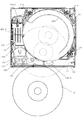
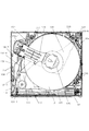
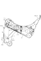
本実施形態は、図1及び図2、図8及び図9に示す通り、以下のような概略構成を有している。
(1)ディスクDを収納するトレイ250が多数積層され、シャーシ101内に昇降可能に設けられたピックシャーシ110
(2)分割されたトレイ250間に振り込まれるピックアーム130(請求項に記載の振り込みアームに対応)
(3)ピックアーム130上に配設され、ディスクDを再生するドライブユニット(ターンテーブル123等を含む)を備えたドライブシャーシ120
(4)スライド移動によってピックアーム130を駆動するピックスイングカムプレート138(請求項に記載の制御部材に対応)
(5)ピックスイングカムプレート138によって駆動されるローディングアーム256(6)ピックシャーシ110に設けられた規制アーム231
(7)ピックシャーシ110に設けられたテンションアーム115
(8)規制アーム231及びテンションアーム115を駆動するスライドリンク114及びリンクアーム113(請求項に記載のリンク機構に対応)
[A. overall structure]
As shown in FIGS. 1, 2, 8, and 9, the present embodiment has the following schematic configuration.
(1) A
(2) Pick
(3)
(4) Pick
(5) Loading
(7)
(8)
[B.各部の構成]
[1.ピックシャーシ(図1〜5)]
ピックシャーシ110は、シャーシ101内に昇降可能に設けられるとともに、その昇降によってディスクD及びトレイ250に干渉しないように、略扇形の空隙が形成されている。ピックシャーシ110の前後左右の側面は、シャーシ101の内側面に沿って、底面から直角に曲げられている。このピックシャーシ110の後面(図3)、右側面(図4)及び前面(図5)には、それぞれピック昇降ピン110−1,2,3がかしめられている。
[B. Configuration of each part]
[1. Pick chassis (Figs. 1-5)]
The
これらのピック昇降ピン110−1,2,3は、シャーシ101に形成された垂直方向のピックガイド溝101−1,2,5に係合している。また、ピック昇降ピン110−1,2,3は、シャーシ101の側面にスライド移動可能に設けられたシフトプレート108,107,106に、それぞれ形成された階段状の溝若しくは穴であるピック昇降カム108−4,107−2,106−2と係合している。従って、シフトプレート108,107,106が同期してスライド移動することにより、ピックシャーシ110が上下動するように構成されているが、そのための機構は説明を省略する。
These pick raising / lowering pins 110-1, 2, 3 are engaged with vertical pick guide grooves 101-1, 2, 5 formed in the
[2.ピックアーム(図1,2,6,7)]
ピックアーム130は、図1及び図2に示すように、ピックシャーシ110の左底面上部に、軸130−1を支軸として回動自在に取り付けられている。ピックアーム130の先端(軸130−1と反対端)には、フック130−5が設けられている。このフック130−5は、ピックアーム130の振り込み時に、ピックシャーシ110の後面側に保持される部分である。つまり、ピックシャーシ110の右後隅には、水平方向の一対のプレートである保持部129が固定されており(図20参照)、このプレート間にフック130−5が保持される構成となっている。
[2. Pick arm (Fig. 1, 2, 6, 7)]
As shown in FIGS. 1 and 2, the
また、ピックアーム130には、後述するピックスイングアーム131の駆動力が伝達される溝若しくは穴である連結カム130−2が形成されている(図6,7参照)。さらに、ピックアーム130には、ターンテーブル123、ピックアップ(図示せず)等、ディスク再生に必要な部材を備えたドライブシャーシ120、ターンテーブル123との間でディスクDを挟持するクランパリング125等を備えたクランプアーム124、ドライブシャーシ120をピックアーム130に対して弾性支持された状態と固定された状態とに切り換えるフローティングロック機構等が設けられているが、詳細は省略する。
Further, the
[3.ピックスイングアーム(図2,6,7)]
ピックスイングアーム131は、ピックアーム130とピックシャーシ110の間に配設されており、ピックシャーシ110の穴に係合する軸131−1を中心に、ピックシャーシ110に回動自在に取り付けられている。ピックスイングアーム131の軸131−1の左裏面には、ローラ131−2が回転自在に取り付けられている。このローラ131−2は、後述するピックスイングカムプレート138の振込みカム138−1に挿通されている。ピックスイングアーム131の先端部には、2段ローラ131−3が回転自在に取り付けられている。この2段ローラ131−3は、ピックアーム130に設けられた連結カム130−2に挿通されている。
[3. Pick swing arm (Fig. 2, 6, 7)]
The
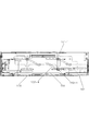
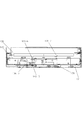
[4.ピックスイングカムプレート(図6〜10)]
ピックスイングカムプレート138は、図8及び図9に示すように、ピックシャーシ110の裏面に前後にスライド移動可能に取り付けられている。このピックスイングカムプレート138の底面に形成された溝若しくは穴である振込みカム138−1は、図6及び図7に示すように、ピックスイングアーム131のローラ131−2が挿通され、後部が前後方向の直線状、前部が円弧状となっている。このため、ピックスイングカムプレート138が後方(A方向)に移動すると、ピックスイングアーム131が時計方向に回動する。そして、このようなピックスイングアーム131の回動に従って、ピックスイングアーム131の前方に取り付けられた2段ローラ131−3は、ピックアーム130に形成された連結カム130−2内を移動しながら、ピックアーム130が反時計方向に回動するように付勢する構成となっている。
[4. Pick swing cam plate (Figs. 6-10)]
As shown in FIGS. 8 and 9, the pick
また、図10に示すように、ピックスイングカムプレート138の左端部が上方に折り曲げられた左側面138−6の前部には、後述するリンクアーム113の回動を制御する山形状のカム138−2が、内側に突出するように一体に形成されている。そして、ピックスイングカムプレート138の左側面138−6の上部の前後には、後述するローディングアーム256を制御する2つの絞り部138−3,138−4が、内側に突出するように、ピックスイングカムプレート138と一体に形成されている。さらに、ピックスイングカムプレート138の左側面138−6の奥側上端には、内側に段曲げされた押上部138−7が形成されている。この押上部138−7は、図1に示すように、クランプアーム124を下から押し上げることにより、ディスクDを挿入するためのクリアランスを確保するものである。
Also, as shown in FIG. 10, a mountain-shaped
[5.ローディングアーム(図2,8,9,11)]
ローディングアーム256は、図8及び図9に示すように、ピックシャーシ110の左上部にかしめられた軸256−1と回動自在に係合している。ローディングアーム256は、ピックシャーシ110との間に設けられたスプリング456によって、時計方向に付勢されている。また、ローディングアーム256の左手前には、ボス部256−2と突起部256−3が形成されている。ボス部256−2、突起部256−3は、ピックスイングカムプレート138のスライド移動に従って、絞り部138−3,138−4若しくは左側面138−6の内側に当接することにより、その回動角度が設定される構成となっている(図18参照)。さらに、ローディングアーム256には、図11に示すように、挿入・排出されるディスクDの左縁が当接しながら通過することにより、ディスクDの方向を変える略コの字状のガイド部256−4が設けられている(図1参照)。
[5. Loading arm (Fig. 2, 8, 9, 11)]
As shown in FIGS. 8 and 9, the
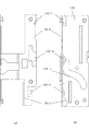
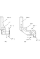
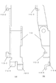
[6.規制アーム(図8,9,12)]
規制アーム231は、図8及び図9に示すように、ピックシャーシ110の前壁に、上下に回動可能に軸支されている。この規制アーム231は、図12に示すように、棒状の規制部231−Aを有しており、その回動に応じて、規制部231−Aが直立して、トレイ250内のディスクDの外縁から僅かに離れた状態で飛び出しを防止する規制位置(図8)と、規制部231−Aが倒れて、トレイ250内のディスクDから退避してディスクDの移動若しくは再生スペースを確保する退避位置(図9)とが切り換わるように構成されている。この切り換えは、後述するスライドリンク114に設けられた押圧部114−1,2が、規制アーム231の軸の上下に設けられた突出部231−1,2に接離することにより行われる。さらに、規制アーム231は、ピックシャーシ110との間に設けられたスプリング231−3によって、規制部231−Aが直立する方向に付勢されている。
[6. Restriction arm (Figs. 8, 9, 12)]
As shown in FIGS. 8 and 9, the
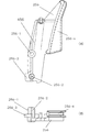
[7.テンションアーム(図8,9,13)]
テンションアーム115は、図8及び図9に示すように、ピックシャーシ110の底面前部に、回動可能に軸支された部材であり、選択対象のトレイ250よりも下方のトレイ250のディスクDの縁を押さえて、飛び出さないようにテンションを与える上下一対のパッド115−1を備えている。このテンションアーム115は、ピックシャーシ110との間に設けられたスプリング115−2を介して、パッド115−1がディスクDから離れる方向に付勢されている。また、テンションアーム115には、後述するスライドリンク114の押圧爪114−3によって付勢されるピン115−3が設けられている。
[7. Tension arm (Figs. 8, 9, 13)]
As shown in FIGS. 8 and 9, the
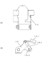
[8.スライドリンク(図8,9,14〜16)]
スライドリンク114は、図14〜16に示すように、ピックシャーシ110の前壁に左右にスライド移動可能に設けられた部材である。このスライドリンク114は、左右の移動端の中間位置に待機するように、ピックシャーシ110との間に配設されたスプリング414によって付勢されている。そして、スライドリンク114の右端近傍には、その左右のスライド移動に従って、規制アーム231の突出部231−1,2を押圧する押圧部114−1,2が設けられている。
[8. Slide link (Figs. 8, 9, 14-16)]
The
すなわち、図16(A)に示すように、スライドリンク114が右側にスライド移動すると、下側の押圧部114−2によって、下側の突出部231−2が付勢され、規制アーム231がスプリング231−3の付勢力に抗して下方に回動するので、規制部231−Aは退避状態となる。一方、図16(B)に示すように、スライドリンク114が左側にスライド移動すると、上側の押圧部114−1によって、上側の突出部231−1が付勢され、規制アーム231がスプリング231−3の付勢力に抗して下方に回動するので、規制部231−Aは退避状態となる。このように、スライドリンク114が左右どちらに移動しても、規制部231−Aは退避状態となるように構成されている。
That is, as shown in FIG. 16A, when the
また、スライドリンク114の内側には、図8,9,14に示すように、その左右のスライド移動に従って、テンションアーム115のピン115−3を付勢することにより、テンションアーム115をスプリング115−2に抗して奥側へ回動させて、パッド115−1をディスクDの外縁に接触させる押圧爪114−3が設けられている。この押圧爪114−3は、滑らかな略凹字形のカム面を有しており、両端の突出部分において、ピン115−3を付勢し、中央の窪みにおいてピン115−3に対する付勢を解くように構成されている。さらに、スライドリンク114の左端には、後述するリンクアーム113の先端部113−4と係合する溝114−4が設けられている。
Further, as shown in FIGS. 8, 9 and 14, the
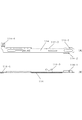
[9.リンクアーム(図8,9,17,18)]
リンクアーム113は、図8,9,17に示すように、後述するディスクガイドプレート112にかしめられた軸上を回動自在に取り付けられており、略コの字状に形成された下面左側には、その前後に2ヶ所の折り曲げ部113−2,3が形成されている。この折り曲げ部113−2,113−3は、図18に示すように、スライド移動するピックスイングカムプレート138に形成されたカム138−2と接離することにより、リンクアーム113を左若しくは右にスライド移動させるものである。また、上記のように、リンクアーム113の先端部113−4は、スライドリンク114の溝114−4に係合している。このため、ピックスイングカムプレート138が前後にスライド移動すると、リンクアーム113が回動するとともに、スライドリンク114が左若しくは右にスライド移動するように構成されている。さらに、リンクアーム113の先端部113−4には、後述するシャッタ103を付勢する付勢部113−5が設けられている。
[9. Link arm (Figs. 8, 9, 17, 18)]
As shown in FIGS. 8, 9, and 17, the
[10.ディスクガイド及びローディングローラ(図2,15,16)]
ピックシャーシ110の前上部には、図15(B)(C),図16(B)に示すように、略コの字状のディスクガイドプレート112が設けられており、このディスクガイドプレート112の内側には、ディスクガイド230が組み付けられている。ディスクガイド230には、ディスクDが挿入、排出される時に、ディスクDの縁をガイドする溝が形成されている。ディスクガイド230の左右には、一体で軸部230−1が形成されており、この左右の軸部230−1は、図15(C)に示すように、ローラ軸受け215,216の長穴部215−1(左は図示を省略)に係合している。ローラ軸受け215,216の中央部には、ローディングローラ401の左右から突出したローラ軸401−1を受ける軸受け部215−2(左は図示省略)が形成されている。さらに、ローラ軸受け216,215の先端部とディスクガイドプレート112の上部との間には、それぞれスプリング402が取り付けられている。このため、ディスクDがローディングローラ401とディスクガイド230との間に挿入されると、ディスクDの厚みだけローディングローラ401が下がり、ローラ軸受け215,216が下方に回動するが、ローディングローラ401には、スプリング402の付勢力によって、ディスクDに圧着する上方向に常時圧力が加えられている。
[10. Disc guide and loading roller (Figs. 2, 15, 16)]
As shown in FIGS. 15B, 15C, and 16B, a substantially U-shaped
また、ディスクガイドプレート112の右側下部には、モータM3が取り付けられ、その軸に圧入されたウォーム203が、ハスバギヤ218−1とウォームギヤ218−2が一体で形成されたハスバウォーム218のハスバギヤ218−1と噛み合っている。ハスバウォーム218は、ディスクガイドプレート112に直立して設けられた軸316に回転自在に取り付けられている。ハスバウォーム218の上部に形成されたウォームギヤ218−2は、ローディングローラ401の軸に圧入されたハスバギヤ217と噛み合っている。これにより、モータM3の作動に従って、ローディングローラ401が回転するように構成されている。
A motor M3 is attached to the lower right side of the
[11.シャッタ(図19)]
シャーシ101の前面には、図19に示すように、ディスクDを挿入・排出するためのディスク挿入口101−7が形成されており、このディスク挿入口101−7は、ディスクDの誤挿入を防止するためのシャッタ103が設けられている。このシャッタ103には、軸103−1、ピン103−2及び2つの屈曲部103−3が設けられており、軸103−1は、シャーシ101に形成された水平方向の溝に、回動可能に且つ水平移動可能に挿通されている。ピン103−2及び2つの屈曲部103−3は、シャーシ101に形成された斜め方向の溝に沿って、移動可能となるように挿通されている。そして、シャッタ103は、シャーシ101との間に設けられたスプリング103−4によって、ディスク挿入口101−7を塞ぐ方向に付勢されている。
[11. Shutter (FIG. 19)]
As shown in FIG. 19, a disk insertion slot 101-7 for inserting / ejecting the disk D is formed on the front surface of the
さらに、シャッタ103の左端には、リンクアーム113の付勢部113−5が当接している。このため、シャッタ103は、リンクアーム113の回動に従って、付勢部113−5により右方向に付勢されると、スプリング103−4の付勢力に抗して右方向に移動しながら、軸103−1を中心に回動してディスク挿入口101−7を開放するように構成されている。
Further, the urging portion 113-5 of the
[12.トレイ(図1,2,20)]
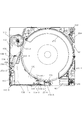
ディスクDが収納され、再生時に分割されるトレイ250は、周知のあらゆる技術を適用可能である。例えば、ピックシャーシ110に積層され、昇降可能に設けられた円弧状のプレートとしてトレイ250を構成し、このトレイ250の周囲に、図1及び図2に示すように、回転するドラムカム210を直立して配設し、ドラムカム210の周囲に形成された階段状の溝に、トレイ250の縁に設けられた爪部を挿通させることにより、ドラムカム210の回動に従って、トレイ250が昇降する構成とすることが考えられる。
[12. Tray (Figs. 1, 2, 20)]
Any known technique can be applied to the
ピックシャーシ110のトレイ250の右後方には、図20に示すように、排出対象となるディスクDを排出方向に付勢するイジェクトアーム254が回動可能に設けられている。イジェクトアーム254は、ピックシャーシ110との間に配設されたスプリング254−1によって、ディスクDから退避する方向に付勢されている。そして、後述するリンクプレート143の一端が、イジェクトアーム254の端部に回動可能に連結されている。
As shown in FIG. 20, an
[13.駆動機構(図21,22)]
上記のピックスイングカムプレート138は、そのスライド移動に従って、規制アーム231の回動、テンションアーム115の回動、ローディングアーム256の回動及びピックアーム130の回動を制御することができる。このピックスイングカムプレート138を駆動するための駆動機構としては、周知のあらゆる技術を適用可能である。例えば、図21及び図22に示すように、シャーシ101に設けられたモータM1、減速機構、平歯車111−1,111−2、円形カムプレート104、リンクプレート119、スライドプレート137の組合せによって、ピックスイングカムプレート138をスライド移動させる以下のような構成とすることが考えられる。すなわち、駆動源となるモータM1は、シャーシ101の左奥隅に取り付けられている。モータM1の回転駆動力は、減速機構を経由して、シャーシ101上に回転自在に取り付けられた平歯車111−1,111−2に伝達される構成となっている。
[13. Drive mechanism (FIGS. 21 and 22)]
The pick
また、シャーシ101の底面には、外周にギヤ溝が形成された円形カムプレート104が、軸104−1を中心に回動可能に取り付けられている。この円形カムプレート104には、後述するリンクプレート119のローラ119−2と係合する溝若しくは穴であるスイング駆動カム104−2が形成されている。リンクプレート119は、シャーシ101の底面上部に、軸119−1を中心として回動可能に取り付けられている。リンクプレート119の一端には、ローラ119−2が回転自在に設けられ、他端には、ピン119−3が一体に形成されている。このローラ119−2は、上記のスイング駆動カム104−2に挿通されている。
Further, a
そして、シャーシ101の左側面には、スライドプレート137が前後にスライド移動可能に設けられている。このスライドプレート137に設けられた連結穴137−1には、リンクプレート119のピン119−3が、回動可能に且つ左右に移動可能に連結されている。スライドプレート137の左側面には、図22に示すように、垂直方向に立ち上げられた当接部137−2が設けられ、この当接部137−2は、ピックスイングカムプレート138に当接している。
A
円形カムプレート104に設けられたスイング駆動カム104−2は、連続した蛇行形状であり、これに係合されたローラ119−2が、円形カムプレート104の回動に従って、軸104−1に対する距離を変えることにより、リンクプレート119を付勢するように構成されている。従って、モータM1の駆動力が、減速機構、平歯車111−1,111−2を経由して円形カムプレート104に伝達されると、円形カムプレート104の回動とともにスイング駆動カム104−2が移動し、これに適宜ローラ119−2が付勢されることにより、リンクプレート119が回動する。そして、リンクプレート119の回動によりスライドプレート137がスライド移動するので、その当接部137−2に接触したピックスイングカムプレート138は、その昇降を許容されつつ、前後にスライド移動するように構成されている。
The swing drive cam 104-2 provided on the
さらに、円形カムプレート104にはボス104−4が突出して設けられ、シャーシ101の奥側底面には、リンクプレート143が回動可能に設けられている。リンクプレート143の一端は、イジェクトアーム254の端部に回動可能に連結されている。リンクプレート143の他端は、円形カムプレート104の回動に従って、上記のボス104−4に付勢されることにより、回動する構成となっている。すなわち、円形カムプレート104の回動により、ボス104−4がリンクプレート143の他端を付勢すると、リンクプレート143の時計方向の回動とともに、イジェクトアーム254がスプリング254−1の付勢力に抗して時計方向に回動し、ディスクDを排出方向に付勢するように構成されている。なお、モータM1、M3は、操作ボタン、センサ等からの入力信号に応じて、所定のプログラムで動作するマイクロコンピュータによって制御される。
Further, a boss 104-4 is protruded from the
[C.作用]
上述したような本実施形態の動作について、まず、ディスク装置の動作の概要を説明し、次に、待機状態、ディスクの搬入、ディスクの収納、ピックアームの振り込み、ディスクの再生、ピックアームの振り出し、ディスクの排出の順に説明する。
[C. Action]
Regarding the operation of the present embodiment as described above, first, an outline of the operation of the disk device will be described, and then the standby state, disk loading, disk storage, pick arm transfer, disk reproduction, pick arm swinging The description will be made in the order of disc ejection.
[1.動作の概要(図1,2,23,24)]
まず、ディスク装置の動作の流れの概要を説明する。すなわち、ディスク挿入口101−7から挿入されたディスクDは、図1,図23(A)(B)に示すように、ローディングローラ401の回動に従って、装置内に引き込まれながら、ローディングアーム256のガイド部256−4に当接することによってその移動方向がトレイ250側に変換されるとともに、ローディングアーム256の回動によりトレイ250側に押圧されるので、選択された段のトレイ250に収納される。
[1. Outline of operation (FIGS. 1, 2, 23 and 24)]
First, an outline of the operation flow of the disk device will be described. That is, as shown in FIGS. 1, 23 (A) and 23 (B), the disk D inserted from the disk insertion slot 101-7 is drawn into the apparatus as the
そして、ディスクDの再生時には、図2,図24(A)(B)に示すように、分割されたトレイ250側に、ピックアーム130を振り込み、ドライブシャーシ120のターンテーブル123に装着されたディスクDの再生が行われる。再生後、ディスクDを排出する際には、ピックアーム130を振り出し、イジェクトアーム254を回動することによってディスクDをトレイ250から押し出す。ディスクDは、ローディングアーム256のガイド部256−4に当接することによって、その移動方向がディスク挿入口101−7へと変換されるとともにローディングローラ401に接し、ローディングローラ401の回動に従って、ディスク挿入口101−7から外部に排出される。
At the time of reproducing the disk D, as shown in FIGS. 2, 24 (A) and 24 (B), the
[2.待機状態]
まず、待機状態においては、図18(A)に示すように、ピックスイングカムプレート138は前方にある。このため、リンクアーム113の前方の折り曲げ部113−3が、ピックスイングカムプレート138のカム138−2に付勢されることにより、リンクアーム113は、反時計方向に回動している。これにより、リンクアーム113の付勢部113−5は、シャッタ103の左端を右方に付勢するので、シャッタ103が上方に回動してディスク挿入口101−7を開放している(図19参照)。
[2. Standby state]
First, in the standby state, as shown in FIG. 18A, the pick
また、このとき、図16(A)に示すように、リンクアーム113の先端部113−4は、スライドリンク114を右方に付勢している。このため、スライドリンク114の下方の押圧部114−2が、規制アーム231の下方の突出部231−2を押圧しており、規制アーム231は、スプリング231−3の付勢力に抗して規制部231−Aが倒れる方向に回動しているので、ディスク挿入口101−7から退避している。また、テンションアーム115のピン115−3は、図9に示すように、スライドリンク114の押圧爪114−3の左側突出部分に当接しているので、スプリング115−2の付勢力に抗して回動し、そのパッド115−1が、ディスク挿入口101−7より下方のディスクD(既に収納されている場合)に対して、トレイ250から飛び出さないようにテンションを与えている。
At this time, as shown in FIG. 16A, the tip 113-4 of the
一方、図18(A)に示すように、ローディングアーム256のボス部256−2は、ピックスイングカムプレート138の左側面138−6に当接しているので、スプリング456の付勢力によって、時計方向に回動している。このため、ローディングアーム256のガイド部256−4は、トレイ250側にある。さらに、ピックスイングカムプレート138の押上部138−7は、クランプアーム124を下から押し上げることにより、ターンテーブル123とクランパリング125との間にディスク挿入のためのクリアランスを確保している。
On the other hand, as shown in FIG. 18A, the boss portion 256-2 of the
[3.ディスク挿入]
上記のような状態で、ディスク挿入口101−7にディスクDを挿入すると、センサ(図示せず)によってディスクDが検知され、モータM3が作動するので、ローディングローラ401が回動することにより、ディスクガイド230との間にディスクDが引き込まれる。ディスクDは、図23(A)(B)に示すように、上方に退避したクランパリング125と、その下方のターンテーブル123との間を通過する。そして、図1に示すように、ディスクDが奥に移動するに従って、ローディングアーム256のガイド部134に当接することによって進路を変え、平面方向から見て斜め右上方向に案内される。その後、ディスクDはローディングローラ401から離れるとともに、ローディングアーム256のガイド部134がスプリング456の付勢力によって、ディスクDをトレイ250側に押し込むので、ディスクDがトレイ250内に収納される。このようなディスクDの収納がセンサによって検出されると、ローディングローラ401が停止する。
[3. Insert disc]
When the disk D is inserted into the disk insertion slot 101-7 in the state as described above, the disk D is detected by a sensor (not shown), and the motor M3 is activated, so that the
[4.ピックアームの振り込み]
次に、分割されたトレイ250側にピックアーム130を振り込む動作を説明する。すなわち、選択されたトレイ250の上下のトレイ250を分割退避させる際には、モータM1の作動で回動する円形カムプレート104によって、リングギヤ105が回動し、スライドプレート137が後方にスライド移動することにより、ピックスイングカムプレート138が、後方へのスライド移動を開始する。すると、図18(B)に示すように、ピックスイングカムプレート138の絞り部138−4によって、ローディングアーム256のボス部256−2が付勢され、ローディングアーム256がスプリング456の付勢力に抗して反時計方向に回動するので、分割時に昇降するディスクDから、ローディングアームのガイド部256−4が退避する。
[4. Pick arm transfer]
Next, an operation of swinging the
これと同時並行的に、リンクアーム113の折り曲げ部113−3は、ピックスイングカムプレート138のカム138−2から解放される。これにより、リンクアーム113の先端部113−4によるスライドリンク114に対する付勢が解かれ、スライドリンク114が、スプリング414の付勢力によって中間位置に来る。すると、図15(A)(B)に示すように、スライドリンク114の押圧部114−2は、規制アーム231の突出部231−2に対する押圧を解くので、規制アーム231は、スプリング231−3の付勢力によって、規制部231−Aが直立する方向に回動し、分割時に昇降するディスクDの飛び出しを防止する。
At the same time, the bent portion 113-3 of the
また、図8に示すように、テンションアーム115のピン115−3は、スライドリンク114の押圧爪114−3の中央窪み部分に当接するので、スプリング115−2の付勢力によって、そのパッド115−1が、ディスク挿入口101−7より下方のディスクD(分割時に昇降する)から離れる方向に退避する。
Further, as shown in FIG. 8, the pin 115-3 of the
以上の状態で、トレイ250が昇降して、選択されたディスクDを収納したトレイ250が位置決めされる。このとき、ピックスイングカムプレート138の後方への移動に従って、ローディングアーム256のボス部256−2が、絞り部138−4から外れて左側面138−6に来る。すると、スプリング456の付勢力によってローディングアーム256が時計方向に回動するので、選択されたディスクDの縁を、ローディングアーム256のガイド部256−4が保持する。
In the above state, the
このようなピックスイングカムプレート138の後方へのスライド移動中に、図7に示すように、振込みカム138−1によって、ピックスイングアーム131のローラ131−2が付勢されるので、ピックスイングアーム131が時計方向に回動する。ピックスイングアーム131の2段ローラ131−3は、ピックアーム130の連結カム130−2に沿って移動するので、ピックアーム130が反時計方向に回動する。そして、図2に示すように、ピックアーム130の先端のフック130−5が、保持部129に挿通されることにより保持されて、回動端に達すると、選択されたディスクDの上下に、クランパリング125とターンテーブル123が来る。
During the backward sliding movement of the pick
[5.ディスク再生]
以上のように振り込まれたクランパリング125とターンテーブル123によって、ディスクDを挟持するとともに、フローティングロックを解除してドライブシャーシ120をフローティング状態とし、トレイ250を退避させる。また、ピックスイングカムプレート138の後方への移動に従って、図18(C)に示すように、その絞り部138−3に、ローディングアーム256の突起部256−3が付勢され、ローディングアーム256がスプリング456の付勢力に抗して反時計方向に回動するので、再生対象となるディスクDから、ローディングアーム256のガイド部256−4が退避する。
[5. Disc playback]
The disk D is clamped by the
また、このとき、リンクアーム113の後方の折り曲げ部113−2が、ピックスイングカムプレート138のカム138−2に付勢されることにより、時計方向に回動する。これにより、リンクアーム113の先端部113−4が、スライドリンク114を左方に付勢するので、図16(B)に示すように、スライドリンク114の下方の押圧部114−2が、規制アーム231の下方の突出部231−2を押圧し、規制アーム231が、スプリング231−3の付勢力に抗して、規制部231−Aが倒れる方向に回動するので、再生されるディスクDから退避する。
At this time, the bent portion 113-2 on the rear side of the
一方、テンションアーム115のピン115−3は、スライドリンク114の押圧爪114−3の右側突出部分に付勢されるので、スプリング115−2の付勢力に抗して、再生されるディスクDより下方のディスクDの縁を押さえて飛び出しを防止する。なお、リンクアーム113の付勢部113−5は、シャッタ103に対する付勢を解き、シャッタ103がスプリング103−4の付勢力によって、下方に回動してディスク挿入口101−7を閉鎖することにより、ディスクDの誤挿入が防止される。
On the other hand, the pin 115-3 of the
そして、スピンドルモータによって回転するターンテーブル123上のディスクDの信号を、光学ピックアップによって読み取る。ディスク再生終了後、トレイ250が上昇してディスクDを保持し、フローティングロックが行われ、ディスクDからクランパリング125が解放される。また、モータM1の作動によりピックスイングカムプレート138が前方へ移動すると、ローディングアーム256の突起部256−3が絞り部138−3から外れて、左側面138−6に来る。すると、スプリング456の付勢力によってローディングアーム256が時計方向に回動するので、再生後のディスクDの縁を、ローディングアームのガイド部256−4が保持する。
Then, the signal of the disk D on the
[6.ピックアームの振り出し]
さらに、ピックスイングカムプレート138が前方へスライド移動すると、ピックスイングカムプレート138に設けられた振込みカム138−1によってローラ131−2が付勢され、ピックスイングアーム131が反時計方向に回動する。ピックスイングアーム131の2段ローラ131−3は、ピックアーム130の連結カム130−2に沿って移動して、ピックアーム130が時計方向に回動する。これにより、ピックアーム130の先端のフック130−5が、保持部129から外れて、ディスクDの上下からクランパリング125とターンテーブル123が離れ、ピックシャーシ110が初期位置に復帰して停止する。
[6. Pick arm swing]
Further, when the pick
再生したディスクDをそのまま収納しておく場合には、選択されたトレイ250と退避していたトレイ250が互いに近接する方向に移動して収納状態に復帰する。このようなトレイ250の昇降時には、図18(B)に示すように、前方へスライド移動するピックスイングカムプレート138の絞り部138−4が、ローディングアーム256のボス部256−2を付勢するので、ローディングアーム256がスプリング456の付勢力に抗して反時計方向に回動する。従って、昇降するディスクDから、ローディングアームのガイド部134が退避する。
When the reproduced disc D is stored as it is, the selected
また、ピックスイングカムプレート138の前進により、リンクアーム113の後方の折り曲げ部113−2は、ピックスイングカムプレート138のカム138−2から外れる。これにより、リンクアーム113の先端部113−4によるスライドリンク114に対する付勢が解かれ、スライドリンク114が、スプリング414の付勢力によって中間位置に来る。すると、図15(A)(B)に示すように、スライドリンク114の押圧部114−2は、規制アーム231の突出部231−2に対する押圧を解くので、規制アーム231は、スプリング231−3の付勢力によって、規制部231−Aが直立する方向に回動し、昇降するディスクDの飛び出しを防止する。
Further, as the pick
また、図8に示すように、テンションアーム115のピン115−3は、スライドリンク114の押圧爪114−3の中央窪み部分に当接するので、スプリング115−2の付勢力によって、そのパッド115−1が、ディスク挿入口101−7より下方の昇降するディスクDから離れる方向に退避する。なお、以上の停止状態から、上述の待機状態(ディスクの挿入・排出が可能な状態)とする場合には、図18(A)に示すように、ピックスイングカムプレート138をさらに前方に移動させる。すると、上述のように、シャッタ103がディスク挿入口101−7を開放し、ピックスイングカムプレート138の押上部138−7が、クランプアーム124を下から押し上げることにより、ターンテーブル123とクランパリング125との間に、ディスク挿入・排出のためのクリアランスを確保する。
Further, as shown in FIG. 8, the pin 115-3 of the
[7.ディスクの排出]
ピックスイングカムプレート138の前方への移動に従って、図18(A)に示すように、リンクアーム113の前方の折り曲げ部113−3が、ピックスイングカムプレート138のカム138−2に付勢されることにより、リンクアーム113が反時計方向に回動する。これにより、リンクアーム113の付勢部113−5は、シャッタ103の左端を右方に付勢するので、シャッタ103が上方に回動してディスク挿入口101−7を開放する。
[7. Eject disc]
As the pick
また、このとき、図16(A)に示すように、リンクアーム113の先端部113−4は、スライドリンク114を右方に付勢する。このため、スライドリンク114の下方の押圧部114−2が、規制アーム231の下方の突出部231−2を押圧し、規制アーム231が、スプリング231−3の付勢力に抗して規制部231−Aが倒れる方向に回動するので、ディスク挿入口101−7から退避する。
At this time, as shown in FIG. 16A, the tip 113-4 of the
また、テンションアーム115のピン115−3は、図9に示すように、スライドリンク114の押圧爪114−3の左側突出部分に当接するので、スプリング115−2の付勢力に抗して回動し、そのパッド115−1が、ディスク挿入口101−7より下方のディスクDに対して、トレイ250から飛び出さないようにテンションを与えている。
Further, as shown in FIG. 9, the pin 115-3 of the
さらに、ローディングアーム256のボス部256−2は、ピックスイングカムプレート138の左側面138−6に当接するので、スプリング456の付勢力によって、時計方向に回動する。このため、ローディングアーム256のガイド部256−4は、トレイ250側にある。
Further, since the boss portion 256-2 of the
上記のような状態で、ディスク挿入口101−7に位置決めされたディスクDの排出指示が入力されると、モータM3,M1が作動して、ローディングローラ401が回動するとともに、イジェクトアーム254が回動してディスクDを付勢する。トレイ250から押し出されたディスクDは、ローディングアーム256のガイド部256−4に当接することによって進路を変え、スプリング456の付勢力によって、ディスクDがローディングローラ401側に押し込まれるので、平面方向から見て下方向に案内される。その後、回転するローディングローラ401によって、ディスク挿入口101−7から排出される。この間、ディスクDは、上方に退避したクランパリング125と、その下方のターンテーブル123との間を通過する。このようなディスクDの排出がセンサによって検出されると、ローディングローラ401が停止する。
In the state as described above, when an instruction to eject the disk D positioned at the disk insertion slot 101-7 is input, the motors M3 and M1 are operated, the
[D.効果]
以上のような本実施形態によれば、トレイ250内に収容されたディスクD(完全に収容された正常時)の縁から僅かに離れた状態で、ディスクDの変位を規制する規制アーム231と、トレイ250内に収容されたディスクDに当接してディスクDの変位を規制するテンションアーム115との組み合せによって、種々の状況に応じたディスクDの飛び出しを防止することができる。特に、スライドリンク114によって、トレイDの昇降時には、規制アーム231が規制位置にありテンションアーム115が退避位置にあるので、ディスクDの昇降を許容しつつ、振動等によりディスクDがトレイ250から変位した場合にはその外縁が規制部231−Aに当接して、飛び出しが防止される。一方、ディスクDの再生若しくは挿排時には、リンクアーム113によって、規制アーム231が退避位置にあり、テンションアーム115が当接位置にあるので、再生若しくは挿排されるディスクDより下方に位置決めされたディスクDが、トレイ150から飛び出すことが防止される。
[D. effect]
According to the present embodiment as described above, the
また、ピックアーム130を駆動させるピックスイングカムプレート138の変位に従って、スライドリンク114及びリンクアーム113を介して、規制アーム231及びテンションアーム115も変位させることができるので、それぞれの駆動用の部材を配設する場合に比べて、機構の簡略化と所要スペースの節約が実現できる。特に、スライドリンク114は左右の両端において、規制アーム231を退避位置として、テンションアーム115を当接位置とすることができるので、ディスク再生時とディスク挿入・排出時とにおいて、前後の相反する方向に移動するピックスイングカムプレート138であっても、これと連動させて規制アーム231及びテンションアーム115を駆動することができる。
Further, the regulating
[E.他の実施形態]
本発明は、上記のような実施形態に限定されるものではない。例えば、トレイを昇降させる機構、ピックスイングカムプレートをスライド移動させる駆動機構等は、上記の実施形態で例示したものには限定されない。また、各部材及びその数、配置位置、配置間隔、動作距離等も自由である。例えば、ピックスイングカムプレートに設けられるカムの形状、位置等も、上述の機能を果たすものであれば、他の態様であってもよい。
[E. Other Embodiments]
The present invention is not limited to the embodiment as described above. For example, the mechanism for raising and lowering the tray and the drive mechanism for sliding the pick swing cam plate are not limited to those exemplified in the above embodiment. Further, each member and the number thereof, the arrangement position, the arrangement interval, the operation distance, and the like are also free. For example, the shape, position, and the like of the cam provided on the pick swing cam plate may be other forms as long as they fulfill the functions described above.
また、本発明は、CDやDVD等を扱うディスク装置に適しているが、これに限定されるものではなく、平板状の記録媒体に広く適用可能である。さらに、本発明は、所要スペースが少なく、振動にも強いため、車載用のディスク装置に適しているが、これに限定されるものでなく、据置型、ポータブル型等、種々のディスク装置にも適用可能である。 Further, the present invention is suitable for a disk device that handles a CD, a DVD, or the like, but is not limited to this, and can be widely applied to a flat recording medium. Furthermore, the present invention is suitable for an in-vehicle disk device because it requires less space and is resistant to vibrations. However, the present invention is not limited to this, and it can be applied to various disk devices such as a stationary type and a portable type. Applicable.
101…シャーシ
101−1,2,5…ピックガイド溝
101−7…ディスク挿入口
103…シャッタ
103−1,104−1,119−1,130−1,131−1,256−1,316…軸
103−2,115−3,119−3…ピン
103−3…屈曲部
103−4,115−2,231−3,254−1,402,414,456…スプリング
104…円形カムプレート
104−2…スイング駆動カム
104−4…ボス
105…リングギヤ
106,107,108…シフトプレート
106−2,107−2,108−4…ピック昇降カム
110…ピックシャーシ
110−1,2,3…ピック昇降ピン
111−1…平歯車
112…ディスクガイドプレート
113…リンクアーム
113−2,3…折り曲げ部
113−4…先端部
113−5…付勢部
114…スライドリンク
114−1,2…押圧部
114−3…押圧爪
114−4…溝
115…テンションアーム
115−1…パッド
119,143…リンクプレート
119−2,131−2…ローラ
120…ドライブシャーシ
123…ターンテーブル
124…クランプアーム
125…クランパリング
129…保持部
130…ピックアーム
130−2…連結カム
130−5…フック
131…ピックスイングアーム
131−3…2段ローラ
134…ガイド部
137…スライドプレート
137−1…連結穴
137−2…当接部
138…ピックスイングカムプレート
138−1…振込みカム
138−2…カム
138−3,138−4…絞り部
138−6…左側面
138−7…押上部
203…ウォーム
210…ドラムカム
215,216…ローラ軸受け
215−1…長穴部
215−2…軸受け部
217,218−1…ハスバギヤ
218…ハスバウォーム
218−2…ウォームギヤ
230…ディスクガイド
230−1…軸部
231…規制アーム
231−1,2…突出部
231−A…規制部
250…トレイ
254…イジェクトアーム
256…ローディングアーム
256−2…ボス部
256−3…突起部
256−4…ガイド部
401…ローディングローラ
401−1…ローラ軸
D…ディスク
M1,M3…モータ
101 ... chassis 101-1, 2, 5 ... pick guide groove 101-7 ...
Claims (4)
前記ディスク収納部に収納されたディスクとディスク挿入位置との間に、ディスクと非接触で介在する規制位置と、前記ディスク収納部に収納されたディスクから退避する退避位置との間を変位可能な規制アームと
前記ディスク収納部に収納されたディスクのうち、再生若しくは挿排されるディスク以外のいずれかのディスクの縁に当接する当接位置と、前記ディスクから離れる退避位置との間を変位可能なテンションアームと、
を有することを特徴とする請求項1記載のディスク装置。 A disk device provided with a drive unit for reproducing a disk, and comprising a transfer arm that transfers the drive unit into a space generated by dividing a disk storage unit that can store a plurality of disks, and a drive mechanism that drives the transfer arm In
It is possible to displace between a restriction position that is not in contact with the disk and a retreat position for retreating from the disk stored in the disk storage section between the disk stored in the disk storage section and the disk insertion position. Displaceable between the abutment position that abuts on the edge of any one of the discs stored in the disc arm and the control arm other than the disc to be played back or inserted, and the retreat position away from the disc Tension arm,
The disk device according to claim 1, comprising:
前記スライドリンクには、その移動両端において、前記規制アームを退避位置に押圧する押圧部が設けられるとともに、前記テンションアームを規制位置に付勢する付勢部が設けられていることを特徴とする請求項2又は請求項3記載のディスク装置。 The link mechanism has a slide link provided to be slidable,
The slide link is provided with a pressing portion that presses the restricting arm to the retracted position at both ends of the slide link, and an urging portion that urges the tension arm to the restricting position. 4. A disk device according to claim 2 or claim 3.
Priority Applications (5)
| Application Number | Priority Date | Filing Date | Title |
|---|---|---|---|
| JP2004107865A JP4482908B2 (en) | 2004-03-31 | 2004-03-31 | Disk unit |
| DE602005024530T DE602005024530D1 (en) | 2004-03-31 | 2005-03-31 | DISK DEVICE |
| US10/594,860 US8014237B2 (en) | 2004-03-31 | 2005-03-31 | Disk device |
| EP05727344A EP1734523B1 (en) | 2004-03-31 | 2005-03-31 | Disc device |
| PCT/JP2005/006381 WO2005096296A1 (en) | 2004-03-31 | 2005-03-31 | Disc device |
Applications Claiming Priority (1)
| Application Number | Priority Date | Filing Date | Title |
|---|---|---|---|
| JP2004107865A JP4482908B2 (en) | 2004-03-31 | 2004-03-31 | Disk unit |
Publications (2)
| Publication Number | Publication Date |
|---|---|
| JP2005293723A true JP2005293723A (en) | 2005-10-20 |
| JP4482908B2 JP4482908B2 (en) | 2010-06-16 |
Family
ID=35326490
Family Applications (1)
| Application Number | Title | Priority Date | Filing Date |
|---|---|---|---|
| JP2004107865A Expired - Fee Related JP4482908B2 (en) | 2004-03-31 | 2004-03-31 | Disk unit |
Country Status (1)
| Country | Link |
|---|---|
| JP (1) | JP4482908B2 (en) |
-
2004
- 2004-03-31 JP JP2004107865A patent/JP4482908B2/en not_active Expired - Fee Related
Also Published As
| Publication number | Publication date |
|---|---|
| JP4482908B2 (en) | 2010-06-16 |
Similar Documents
| Publication | Publication Date | Title |
|---|---|---|
| JP4482908B2 (en) | Disk unit | |
| JP4482906B2 (en) | Disk unit | |
| JP4420714B2 (en) | Disk unit | |
| CN101751954B (en) | Disk device | |
| JP4482907B2 (en) | Disk unit | |
| JP2003168254A (en) | Disk unit | |
| JP4420717B2 (en) | Drive unit transfer device and disk device | |
| JP4420718B2 (en) | Floating lock device | |
| EP1734523B1 (en) | Disc device | |
| JP4563712B2 (en) | Disk unit | |
| US20060242656A1 (en) | Changer for optical recording media | |
| CN1957412B (en) | Disk selection device and disk device | |
| JP4532153B2 (en) | Disc clamp device | |
| CN101567200A (en) | Light disk device | |
| JP4482909B2 (en) | Disk selection device and disk device | |
| JP4482910B2 (en) | Floating lock device | |
| JP4420716B2 (en) | Disk selection device and disk device | |
| EP1734520B1 (en) | Disk clamp device | |
| CN100456374C (en) | Disk holding device | |
| JP3612234B2 (en) | Automatic carrier regeneration device | |
| JP2006216186A (en) | Disk housing device and disk device | |
| WO2005096297A1 (en) | Floating lock device | |
| JP2005293741A (en) | Drive unit shaking-in device | |
| WO2005096295A1 (en) | Disk selection device and disk device | |
| JPH10275401A (en) | Disk changer device and disk magazine device |
Legal Events
| Date | Code | Title | Description |
|---|---|---|---|
| A621 | Written request for application examination |
Free format text: JAPANESE INTERMEDIATE CODE: A621 Effective date: 20070216 |
|
| A131 | Notification of reasons for refusal |
Free format text: JAPANESE INTERMEDIATE CODE: A131 Effective date: 20091110 |
|
| A521 | Written amendment |
Free format text: JAPANESE INTERMEDIATE CODE: A523 Effective date: 20091225 |
|
| TRDD | Decision of grant or rejection written | ||
| A711 | Notification of change in applicant |
Free format text: JAPANESE INTERMEDIATE CODE: A711 Effective date: 20100212 |
|
| A01 | Written decision to grant a patent or to grant a registration (utility model) |
Free format text: JAPANESE INTERMEDIATE CODE: A01 Effective date: 20100216 |
|
| A01 | Written decision to grant a patent or to grant a registration (utility model) |
Free format text: JAPANESE INTERMEDIATE CODE: A01 |
|
| A521 | Written amendment |
Free format text: JAPANESE INTERMEDIATE CODE: A821 Effective date: 20100212 |
|
| A61 | First payment of annual fees (during grant procedure) |
Free format text: JAPANESE INTERMEDIATE CODE: A61 Effective date: 20100312 |
|
| R150 | Certificate of patent or registration of utility model |
Ref document number: 4482908 Country of ref document: JP Free format text: JAPANESE INTERMEDIATE CODE: R150 Free format text: JAPANESE INTERMEDIATE CODE: R150 |
|
| FPAY | Renewal fee payment (event date is renewal date of database) |
Free format text: PAYMENT UNTIL: 20130402 Year of fee payment: 3 |
|
| FPAY | Renewal fee payment (event date is renewal date of database) |
Free format text: PAYMENT UNTIL: 20140402 Year of fee payment: 4 |
|
| R250 | Receipt of annual fees |
Free format text: JAPANESE INTERMEDIATE CODE: R250 |
|
| R250 | Receipt of annual fees |
Free format text: JAPANESE INTERMEDIATE CODE: R250 |
|
| R250 | Receipt of annual fees |
Free format text: JAPANESE INTERMEDIATE CODE: R250 |
|
| R250 | Receipt of annual fees |
Free format text: JAPANESE INTERMEDIATE CODE: R250 |
|
| R250 | Receipt of annual fees |
Free format text: JAPANESE INTERMEDIATE CODE: R250 |
|
| R250 | Receipt of annual fees |
Free format text: JAPANESE INTERMEDIATE CODE: R250 |
|
| LAPS | Cancellation because of no payment of annual fees |