JP2005293653A - Optical disk device - Google Patents
Optical disk device Download PDFInfo
- Publication number
- JP2005293653A JP2005293653A JP2004103766A JP2004103766A JP2005293653A JP 2005293653 A JP2005293653 A JP 2005293653A JP 2004103766 A JP2004103766 A JP 2004103766A JP 2004103766 A JP2004103766 A JP 2004103766A JP 2005293653 A JP2005293653 A JP 2005293653A
- Authority
- JP
- Japan
- Prior art keywords
- traverse
- load
- detecting
- tracking error
- movement
- Prior art date
- Legal status (The legal status is an assumption and is not a legal conclusion. Google has not performed a legal analysis and makes no representation as to the accuracy of the status listed.)
- Pending
Links
Images
Landscapes
- Moving Of The Head For Recording And Reproducing By Optical Means (AREA)
Abstract
【課題】従来の方式に比べて、精度の高いトラバース負荷検出を可能にする光ディスク装置を提供する。
【解決手段】システムコントローラ5からトラバースモータ3に固定波高値のパルス電圧を一定時間与えた後にトラッキングサーボをオンにし、その間に発生するトラッキングエラー信号から移動した分のトラック本数を計測し、トラバース負荷検出手段7は、その計測本数から移動量すなわちトラバース負荷を検出し、1箇所のトラバース負荷のばらつきに依存せずに、移動箇所全体の平均的な負荷が得られ、精度の高いトラバース負荷検出を行える。また、トラバース移動量は横断したトラック本数ではなく、移動前後のアドレスから算出することもできる。
【選択図】図1An optical disc apparatus capable of detecting a traverse load with higher accuracy than a conventional method is provided.
A tracking servo is turned on after a fixed voltage pulse voltage is applied to a traverse motor 3 from a system controller 5 for a certain period of time, and the number of tracks moved from a tracking error signal generated during that time is measured, and a traverse load is measured. The detecting means 7 detects the amount of movement, that is, the traverse load from the number of measurements, and can obtain an average load of the entire moving location without depending on the variation of the traverse load at one location, thereby detecting the traverse load with high accuracy. Yes. Further, the traverse movement amount can be calculated not from the number of traversed tracks but from the addresses before and after the movement.
[Selection] Figure 1
Description
本発明は、光ディスク装置に係り、特に光ピックアップを移動させるトラバースの負荷を検出し、その負荷ばらつきを吸収する光ディスク装置に関するものである。 The present invention relates to an optical disc apparatus, and more particularly to an optical disc apparatus that detects a traverse load for moving an optical pickup and absorbs the load variation.
光ディスク装置はランダムアクセス性、媒体交換性、収納性等において総合的に他の磁気テープや磁気ディスク等の媒体に比べ優れている。近年、光ディスク装置は情報関連分野のみならず民生機器の分野にも浸透してきており、光ディスク装置の低コスト化が進んでいる。あらゆる要素部品の削減や低コスト化が進む中、光ピックアップを移動させるトラバースの負荷ばらつきが大きくなっており、負荷ばらつきを高精度で吸収することが求められている。 The optical disk device is generally superior to other media such as a magnetic tape and a magnetic disk in terms of random accessibility, medium exchange, and storage. In recent years, optical disk devices have penetrated not only information-related fields but also consumer electronics fields, and the cost of optical disk devices has been reduced. As the number of component parts is reduced and the cost is reduced, the load variation of the traverse for moving the optical pickup is increasing, and it is required to absorb the load variation with high accuracy.
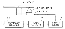
従来、トラバースの負荷を検出し、負荷ばらつきを吸収する光ディスク装置は、特許文献1の特開平10−334473号公報のものや、特許文献1における機械的負荷の変動や温度変化によるトラバース機構の機械的負荷変動の影響を避ける目的の、特許文献2の特開2002−352447号公報のものが知られている。以下、特許文献1に開示されている従来のトラバース負荷ばらつきの検出方法について、図3のブロック図と図4のグラフを用いて説明する。 Conventionally, an optical disc apparatus that detects a traverse load and absorbs load variations is disclosed in Japanese Patent Application Laid-Open No. 10-334473 of Patent Document 1, or a machine of a traverse mechanism according to a mechanical load variation or temperature change in Patent Document 1. Japanese Patent Laid-Open No. 2002-352447 of Patent Document 2 is known for the purpose of avoiding the influence of dynamic load fluctuations. Hereinafter, a conventional method for detecting a variation in traverse load disclosed in Patent Document 1 will be described with reference to the block diagram of FIG. 3 and the graph of FIG.
図3において、光ディスク装置は、情報が記録されている光ディスク11にレーザーを照射させ反射光を受光する光ピックアップ12と、光ピックアップ12を移動させるトラバース13と、光ピックアップ12が受光した信号からトラッキングエラーを検出するトラッキングエラー信号生成手段14と、トラッキングエラー信号生成手段14により検出した信号から次の動作を決定するシステムコントローラ15と、システムコントローラ15の決定からトラバース13を駆動させる制御信号を出力するトラバース制御手段16で構成される。
In FIG. 3, the optical disk apparatus tracks an optical pickup 12 that irradiates a laser onto an optical disk 11 on which information is recorded and receives reflected light, a traverse 13 that moves the optical pickup 12, and a signal received by the optical pickup 12. A tracking error signal generating means 14 for detecting an error, a
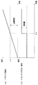
この光ディスク装置のトラバース負荷検出方法について、図4を用いて説明する。まず、システムコントローラ15はフォーカスサーボおよびトラッキングサーボを動作可(オン)とし、トラバースサーボを動作不可(オフ)として光ピックアップ12からのトラッキングエラー信号(グラフb)を測定する。システムコントローラ15は、グラフaのようにトラバースモータ電圧を徐々に上昇させ、時点toでトラバース機構が動いた瞬間の印加電圧(起動電圧)voとトラッキング誤差信号のレベル(移動量)とからトラバースサーボのループゲインを算出し、決定する。トラバース機構への外乱(起動電圧)によって発生する誤差信号(移動量)からトラバースサーボのループゲインを決定するので、トラバース機構の部品のバラツキや環境温度変化による負荷変動の影響を受けにくくすることができる。
しかしながら上述した従来の光ディスク装置では、一つの箇所で徐々にトラバースモータの電圧を上げる方法でトラバースの負荷ばらつきを検出するため、負荷検出の精度が低く、そのため、トラバースの負荷検出結果そのものがばらつき、トラバース負荷ばらつきを安定して吸収できないという課題がある。 However, in the conventional optical disk apparatus described above, since the load variation of the traverse is detected by a method of gradually increasing the voltage of the traverse motor at one place, the load detection accuracy is low, and therefore, the traverse load detection result itself varies, There is a problem that the variation in the traverse load cannot be absorbed stably.
本発明は、従来の方式に比べて、精度の高いトラバース負荷検出を可能にする光ディスク装置を提供するものである。 The present invention provides an optical disc apparatus that enables detection of a traverse load with higher accuracy than conventional methods.
この課題を解決するために、本発明による光ディスク装置では、情報が記録されている光ディスクにレーザーを照射させ反射光を受光する光ピックアップと、前記光ピックアップを移動させるトラバースと、前記光ピックアップが受光した信号からトラッキングエラーを検出するトラッキングエラー信号生成手段と、前記トラッキングエラー信号生成手段により検出した信号から次の動作を決定するシステムコントローラと、前記システムコントローラの決定から前記トラバースを駆動させる制御信号を出力するトラバース制御手段と、前記トラバースの負荷を検出するトラバース負荷検出手段とで構成される。 In order to solve this problem, in an optical disc apparatus according to the present invention, an optical pickup that irradiates a laser onto an optical disc on which information is recorded and receives reflected light, a traverse that moves the optical pickup, and the optical pickup receive light. Tracking error signal generating means for detecting a tracking error from the detected signal, a system controller for determining the next operation from the signal detected by the tracking error signal generating means, and a control signal for driving the traverse based on the determination of the system controller It comprises traverse control means for outputting and traverse load detection means for detecting the load of the traverse.
この構成により、トラッキングサーボオンの状態までディスクの起動を行い、システムコントローラからトラバースモータに固定波高値のパルス電圧を一定時間与え、そのときに発生するトラッキングエラー信号から移動した分のトラック本数を計測し、その計測本数から移動量すなわちトラバース負荷を検出することができる。 With this configuration, the disk is started up until the tracking servo is turned on, a fixed peak voltage pulse voltage is given to the traverse motor from the system controller for a certain period of time, and the number of tracks moved from the tracking error signal generated at that time is measured. The amount of movement, that is, the traverse load can be detected from the measured number.
またこの構成において、アドレスリード可能の状態までディスクの起動を行い、現在のアドレス位置を記憶し、システムコントローラからトラバースモータに固定波高値のパルス電圧を一定時間与え、移動後にアドレスリードを行い、その前後のアドレス位置から移動量すなわちトラバース負荷を検出することもできる。 In this configuration, the disk is started until the address can be read, the current address position is stored, a pulse voltage of a fixed peak value is given from the system controller to the traverse motor for a certain period of time, address read is performed after movement, It is also possible to detect the movement amount, that is, the traverse load from the front and rear address positions.
本発明により、従来の方式に比べて、精度の高いトラバース負荷検出を可能にすることができる。 According to the present invention, it is possible to detect a traverse load with higher accuracy than in the conventional method.
以下本発明の実施の形態について、図面を用いて説明する。 Embodiments of the present invention will be described below with reference to the drawings.
(実施の形態1)
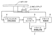
図1は本発明の実施の形態1における光ディスク装置のブロック図である。図1に示す光ディスク装置は、情報が記録されている光ディスク1にレーザーを照射させ反射光を受光する光ピックアップ2と、前記光ピックアップ2を移動させるトラバース3と、前記光ピックアップ2が受光した信号からトラッキングエラーを検出するトラッキングエラー信号生成手段4と、前記トラッキングエラー生成手段4により検出した信号から次の動作を決定するシステムコントローラ5と、前記システムコントローラ5の決定から前記トラバースを駆動させる制御信号を出力するトラバース制御手段6と、前記トラバース3の負荷を検出するトラバース負荷検出手段7で構成される。
(Embodiment 1)
FIG. 1 is a block diagram of an optical disc apparatus according to Embodiment 1 of the present invention. The optical disk apparatus shown in FIG. 1 has an optical pickup 2 that receives a reflected light by irradiating a laser onto an optical disk 1 on which information is recorded, a traverse 3 that moves the optical pickup 2, and a signal that the optical pickup 2 receives. Tracking error signal generating means 4 for detecting a tracking error from the system, a
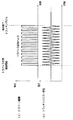
この光ディスク装置の実施の形態1におけるトラバース負荷検出方法について、図2を用いて説明する。まず、情報が記録されている光ディスク1を起動させ、システムコントローラ5により光ピックアップ2で光ディスク1に対してフォーカスサーボをかける。このときにトラッキングサーボもかけてもよいが、トラバース負荷検出時にトラッキングサーボは外れるので、どちらでも構わない。
A traverse load detection method according to the first embodiment of the optical disc apparatus will be described with reference to FIG. First, the optical disk 1 on which information is recorded is activated, and the
その後、システムコントローラ5は図2(a)のように、ある一定の波高値・一定周期を持ったトラバース駆動パルスを、一定時間だけトラバース制御手段6によりトラバース3に印加する。このときのパルスの波高値・周期および印加時間は負荷の大きなトラバースでも動くように設定しておく。
Thereafter, as shown in FIG. 2A, the
また、実際の移動量としては、約1cm程度になるようにする。これは、8cm径のディスクでも内外周を突き抜けないようにするためであり、使用するメカニズムの中で負荷の軽いもので印加パルスを決定するとよい。ここで、一つの実例として、上記のように負荷最大のトラバースでも動く100Hzの周期のパルスを、負荷最小のトラバースで約1cmの移動が生じる時間だけ印加すると、同じ印加パルスでは負荷最大のトラバースで約0.5cmの移動という結果を得た。当然この結果はメカニズムの特性に依存する。 Further, the actual moving amount is set to about 1 cm. This is to prevent an 8 cm diameter disk from penetrating the inner and outer peripheries, and the applied pulse should be determined with a light load among the mechanisms used. Here, as an example, if a pulse with a period of 100 Hz that moves even with the maximum load traverse as described above is applied for a time that causes a movement of about 1 cm with the minimum load traverse, the maximum applied traverse with the same applied pulse. A result of movement of about 0.5 cm was obtained. Of course, this result depends on the characteristics of the mechanism.
このようなトラバース駆動パルスの印加により、トラバース3が移動し、移動量に合わせて光ディスク1のトラックを横断することになるので、トラッキングエラー信号生成手段4により図2の(b)のようなトラッキングエラー信号が発生する。 By applying such a traverse drive pulse, the traverse 3 moves and traverses the track of the optical disc 1 in accordance with the amount of movement. Therefore, the tracking error signal generating means 4 performs tracking as shown in FIG. An error signal is generated.
トラバース駆動パルス印加後、トラバースの移動が収まるタイミングでトラッキングサーボをかける。この間のトラッキングエラー信号から、横断したトラック本数がわかるので、再生を行っているメディアのトラックピッチからトラバース負荷検出手段7により、トラバースの移動量を計算することができる。トラバース負荷の大きさと固定駆動パルスによるトラバース移動量は反比例するので、この移動量からトラバース負荷を検出することができる。 After applying the traverse drive pulse, tracking servo is applied at the timing when the traverse movement stops. Since the number of traversed tracks can be known from the tracking error signal during this time, the traverse load detecting means 7 can calculate the amount of traversal movement from the track pitch of the medium being reproduced. Since the magnitude of the traverse load and the traverse movement amount by the fixed drive pulse are inversely proportional, it is possible to detect the traverse load from this movement amount.
本実施形態によれば、従来の方式に比べ、1箇所の位置の負荷に依存せずに、移動箇所全体の平均的な負荷が測定結果に出てくるので、より精度の高いトラバース負荷検出を行うことができる。トラバース負荷検出後は、結果をシステムコントローラ5に記憶させ、トラバースループサーボのゲイン、トラバース移動やトラバースシークの設定に反映させる。
According to this embodiment, compared to the conventional method, the average load of the entire moving part appears in the measurement result without depending on the load at one position, so that more accurate traverse load detection can be performed. It can be carried out. After detecting the traverse load, the result is stored in the
(実施の形態2)
実施の形態2においても、実施の形態1で用いた光ディスク装置のブロック図で説明する。この光ディスク装置の実施の形態2におけるトラバース負荷検出方法について、同じく図2を用いて説明する。まず、情報が記録されている光ディスク1を起動させ、システムコントローラ5により光ピックアップ2で光ディスク1に対してフォーカスサーボ・トラッキングサーボをかけてアドレスリードを行い、現在位置のアドレスを記憶する。その後、システムコントローラ5は図2(a)のようにある一定の波高値・周期を持ったトラバース駆動パルスを、一定時間だけトラバース制御手段6を通してトラバース3に印加する。このときのパルスの波高値・周期および印加時間は負荷の大きなトラバースでも動くように設定しておく。
(Embodiment 2)
The second embodiment is also described with reference to a block diagram of the optical disk device used in the first embodiment. A traverse load detection method according to the second embodiment of the optical disc apparatus will be described with reference to FIG. First, the optical disk 1 on which information is recorded is activated, and the
また、実際の移動量としては、約1cm程度になるようにする。これは、8cm径のディスクでも内外周を突き抜けないようにするためであり、使用するメカニズムの中で負荷の軽いもので印加パルスを決定するとよい。ここで、一つの実例として、上記のように負荷最大のトラバースでも動く100Hzの周期のパルスを、負荷最小のトラバースで約1cmの移動が生じる時間だけ印加すると、同じ印加パルスでは負荷最大のトラバースで約0.5cmの移動という結果を得た。当然この結果はメカニズムの特性に依存する。 In addition, the actual movement amount is about 1 cm. This is to prevent an 8 cm diameter disk from penetrating the inner and outer peripheries, and the applied pulse should be determined with a light load among the mechanisms used. Here, as an example, if a pulse with a period of 100 Hz that moves even with the maximum load traverse as described above is applied for a time that causes a movement of about 1 cm with the minimum load traverse, the maximum applied traverse with the same applied pulse. A result of movement of about 0.5 cm was obtained. Of course, this result depends on the characteristics of the mechanism.
このようなトラバース駆動パルスの印加により、トラバース3が移動し、移動量に合わせて光ディスク1のトラックを横断することになるので、トラッキングエラー信号生成手段4により図2の(b)のようなトラッキングエラー信号が発生する。トラバース駆動パルス印加後、トラバースの移動が収まるタイミングでトラッキングサーボをかける。この後アドレスリードを行い、移動後のアドレスを記憶する。移動前後のアドレスからトラバース負荷検出手段7により、トラバースの移動量を計算することができる。 By applying such a traverse drive pulse, the traverse 3 moves and traverses the track of the optical disc 1 in accordance with the amount of movement. Therefore, the tracking error signal generating means 4 performs tracking as shown in FIG. An error signal is generated. After applying the traverse drive pulse, tracking servo is applied at the timing when the traverse movement stops. Thereafter, an address read is performed and the address after the movement is stored. The traverse load detection means 7 can calculate the amount of traverse movement from the addresses before and after the movement.
トラバース負荷の大きさと固定駆動パルスによるトラバース移動量は反比例するので、この移動量からトラバース負荷を検出することができる。従来の方式に比べ、1箇所の位置の負荷に依存せずに、移動箇所全体の平均的な負荷が測定結果に出てくるので、より精度の高いトラバース負荷検出を行うことができる。 Since the magnitude of the traverse load and the traverse movement amount by the fixed drive pulse are inversely proportional, the traverse load can be detected from this movement amount. Compared to the conventional method, the average load of the entire moving part appears in the measurement result without depending on the load at one position, so that it is possible to detect the traverse load with higher accuracy.
また、実施の形態1の方式よりもディスクのアドレス位置で移動量を計算するので、トラッキングエラー信号の品位が悪い状態では、実施の形態2の方が有利である。トラバース負荷検出後は、システムコントローラ5に結果を記憶させ、トラバースループサーボのゲイン、トラバース移動やトラバースシークの設定に反映させる。
Further, since the movement amount is calculated at the address position of the disk as compared with the method of the first embodiment, the second embodiment is more advantageous in a state where the quality of the tracking error signal is poor. After detecting the traverse load, the result is stored in the
以上のように本発明によれば、従来のトラバース負荷検出の方式のように1箇所の負荷に依存しないので、精度よくトラバース負荷を検出することができるという有利な効果が得られ、産業上の利用可能性大なるものである。 As described above, according to the present invention, since it does not depend on a single load as in the conventional traverse load detection method, an advantageous effect that a traverse load can be detected with high accuracy can be obtained. The availability is great.
1 光ディスク
2 光ピックアップ
3 トラバース
4 トラッキングエラー信号生成手段
5 システムコントローラ
6 トラバース制御手段
7 トラバース負荷検出手段
DESCRIPTION OF SYMBOLS 1 Optical disk 2 Optical pick-up 3
Claims (2)
前記光ピックアップを移動させるトラバースと、
前記光ピックアップが受光した信号からトラッキングエラーを検出するトラッキングエラー信号生成手段と、
前記トラッキングエラー信号生成手段により検出した信号から次の動作を決定するシステムコントローラと、
前記システムコントローラの決定から前記トラバースを駆動させる制御信号を出力するトラバース制御手段と、
前記トラバースの負荷を検出するトラバース負荷検出手段とを備え、
前記光ディスク再生時にシステムコントローラは前記トラバース制御手段から固定駆動パルスを出力させて前記トラバースを駆動し、前記トラバース負荷検出手段は検出されるトラッキングエラー信号から前記トラバースの移動量を検出して前記トラバースの負荷を検出することを特徴とする光ディスク装置。 An optical pickup that irradiates an optical disc with a laser and receives reflected light; and
A traverse for moving the optical pickup;
Tracking error signal generating means for detecting a tracking error from a signal received by the optical pickup;
A system controller for determining the next operation from the signal detected by the tracking error signal generating means;
Traverse control means for outputting a control signal for driving the traverse from the determination of the system controller;
Traverse load detection means for detecting the load of the traverse,
During reproduction of the optical disk, the system controller drives the traverse by outputting a fixed drive pulse from the traverse control means, and the traverse load detection means detects the amount of movement of the traverse from the detected tracking error signal. An optical disc apparatus for detecting a load.
前記光ピックアップを移動させるトラバースと、
前記光ピックアップが受光した信号からトラッキングエラーを検出するトラッキングエラー信号生成手段と、
前記トラッキングエラー信号生成手段により検出した信号から次の動作を決定するシステムコントローラと、
前記システムコントローラの決定から前記トラバースを駆動させる制御信号を出力するトラバース制御手段と、
前記光ディスクのアドレスから前記トラバースの移動量を計算して前記トラバースの負荷を検出するトラバース負荷検出手段とを備え、
記光ディスク再生時に前記トラバース制御手段から固定駆動パルスを出力させて前記トラバースを駆動し、前記トラバース負荷検出手段は駆動前後の前記光ディスクのアドレスから前記トラバースの移動量を計算して前記トラバースの負荷を検出することを特徴とする光ディスク装置。 An optical pickup that irradiates an optical disc with a laser and receives reflected light; and
A traverse for moving the optical pickup;
Tracking error signal generating means for detecting a tracking error from a signal received by the optical pickup;
A system controller for determining the next operation from the signal detected by the tracking error signal generating means;
Traverse control means for outputting a control signal for driving the traverse from the determination of the system controller;
Traverse load detection means for calculating the amount of traverse movement from the address of the optical disc and detecting the traverse load;
When the optical disc is played, the traverse control means outputs a fixed drive pulse to drive the traverse, and the traverse load detection means calculates the amount of traverse movement from the address of the optical disc before and after driving to calculate the traverse load. An optical disc apparatus characterized by detecting.
Priority Applications (1)
| Application Number | Priority Date | Filing Date | Title |
|---|---|---|---|
| JP2004103766A JP2005293653A (en) | 2004-03-31 | 2004-03-31 | Optical disk device |
Applications Claiming Priority (1)
| Application Number | Priority Date | Filing Date | Title |
|---|---|---|---|
| JP2004103766A JP2005293653A (en) | 2004-03-31 | 2004-03-31 | Optical disk device |
Publications (1)
| Publication Number | Publication Date |
|---|---|
| JP2005293653A true JP2005293653A (en) | 2005-10-20 |
Family
ID=35326434
Family Applications (1)
| Application Number | Title | Priority Date | Filing Date |
|---|---|---|---|
| JP2004103766A Pending JP2005293653A (en) | 2004-03-31 | 2004-03-31 | Optical disk device |
Country Status (1)
| Country | Link |
|---|---|
| JP (1) | JP2005293653A (en) |
Cited By (1)
| Publication number | Priority date | Publication date | Assignee | Title |
|---|---|---|---|---|
| JP2008293582A (en) * | 2007-05-24 | 2008-12-04 | Kenwood Corp | Optical pickup sled control device and method |
-
2004
- 2004-03-31 JP JP2004103766A patent/JP2005293653A/en active Pending
Cited By (1)
| Publication number | Priority date | Publication date | Assignee | Title |
|---|---|---|---|---|
| JP2008293582A (en) * | 2007-05-24 | 2008-12-04 | Kenwood Corp | Optical pickup sled control device and method |
Similar Documents
| Publication | Publication Date | Title |
|---|---|---|
| US20010048646A1 (en) | Disc eccentricity measuring apparatus and method thereof and apparatus for recording and/or reproducing disc-shaped recording medium | |
| JP2001243637A (en) | Focus pull-in method and optical disk device | |
| US7782724B2 (en) | Information reproducing apparatus and method for measuring surface deflection | |
| JP3611725B2 (en) | Optical disk device | |
| JP4614825B2 (en) | Track jump control method for optical disc apparatus | |
| JP3565275B2 (en) | Focus search method | |
| JP2000339709A (en) | Optical disk recording and playback device | |
| JP2008262625A (en) | Optical disk device | |
| KR20060118617A (en) | Multi-layered optical disc reader / writer with improved layer jump | |
| KR100606671B1 (en) | Actuator vibration prevention method of optical record player | |
| JP2000082225A (en) | Optical disc player | |
| KR100697523B1 (en) | Stabilizer and method for optical disk seek | |
| JP2001093172A (en) | Optical disk drive | |
| JP2003030878A (en) | Wobble signal detection circuit of optical disk recording / reproducing device | |
| JP2006185482A (en) | Optical pickup tilt correction control apparatus and tilt correction method | |
| JP2005063566A (en) | Optical disk reproducing device | |
| JP3851177B2 (en) | Laser output setting method for optical disc recording / reproducing apparatus | |
| JP2006344302A (en) | Thread motor drive control method in optical disk drive | |
| JP2002133672A (en) | Disk unit | |
| KR20070014055A (en) | Optical disc drive device and signal recording method | |
| JPH11213398A (en) | Disk recording or playback device | |
| JP2000090451A (en) | Focus bias setting device | |
| JP2006134472A (en) | Track jump control method of optical disk device | |
| JP2006134471A (en) | Track jump control method of optical disk device | |
| JP2008084400A (en) | Optical disk apparatus |