JP2005293630A - Hologram recording apparatus, hologram reproducing apparatus, hologram recording method, hologram reproducing method, and hologram recording medium - Google Patents
Hologram recording apparatus, hologram reproducing apparatus, hologram recording method, hologram reproducing method, and hologram recording medium Download PDFInfo
- Publication number
- JP2005293630A JP2005293630A JP2004102712A JP2004102712A JP2005293630A JP 2005293630 A JP2005293630 A JP 2005293630A JP 2004102712 A JP2004102712 A JP 2004102712A JP 2004102712 A JP2004102712 A JP 2004102712A JP 2005293630 A JP2005293630 A JP 2005293630A
- Authority
- JP
- Japan
- Prior art keywords
- light
- hologram recording
- recording medium
- phase modulation
- modulation element
- Prior art date
- Legal status (The legal status is an assumption and is not a legal conclusion. Google has not performed a legal analysis and makes no representation as to the accuracy of the status listed.)
- Pending
Links
Images


Classifications
-
- G—PHYSICS
- G11—INFORMATION STORAGE
- G11B—INFORMATION STORAGE BASED ON RELATIVE MOVEMENT BETWEEN RECORD CARRIER AND TRANSDUCER
- G11B7/00—Recording or reproducing by optical means, e.g. recording using a thermal beam of optical radiation by modifying optical properties or the physical structure, reproducing using an optical beam at lower power by sensing optical properties; Record carriers therefor
- G11B7/12—Heads, e.g. forming of the optical beam spot or modulation of the optical beam
- G11B7/135—Means for guiding the beam from the source to the record carrier or from the record carrier to the detector
- G11B7/1372—Lenses
- G11B7/1374—Objective lenses
-
- G—PHYSICS
- G11—INFORMATION STORAGE
- G11B—INFORMATION STORAGE BASED ON RELATIVE MOVEMENT BETWEEN RECORD CARRIER AND TRANSDUCER
- G11B7/00—Recording or reproducing by optical means, e.g. recording using a thermal beam of optical radiation by modifying optical properties or the physical structure, reproducing using an optical beam at lower power by sensing optical properties; Record carriers therefor
- G11B7/004—Recording, reproducing or erasing methods; Read, write or erase circuits therefor
- G11B7/0065—Recording, reproducing or erasing by using optical interference patterns, e.g. holograms
-
- G—PHYSICS
- G03—PHOTOGRAPHY; CINEMATOGRAPHY; ANALOGOUS TECHNIQUES USING WAVES OTHER THAN OPTICAL WAVES; ELECTROGRAPHY; HOLOGRAPHY
- G03H—HOLOGRAPHIC PROCESSES OR APPARATUS
- G03H1/00—Holographic processes or apparatus using light, infrared or ultraviolet waves for obtaining holograms or for obtaining an image from them; Details peculiar thereto
- G03H1/26—Processes or apparatus specially adapted to produce multiple sub- holograms or to obtain images from them, e.g. multicolour technique
- G03H1/28—Processes or apparatus specially adapted to produce multiple sub- holograms or to obtain images from them, e.g. multicolour technique superimposed holograms only
-
- G—PHYSICS
- G11—INFORMATION STORAGE
- G11B—INFORMATION STORAGE BASED ON RELATIVE MOVEMENT BETWEEN RECORD CARRIER AND TRANSDUCER
- G11B7/00—Recording or reproducing by optical means, e.g. recording using a thermal beam of optical radiation by modifying optical properties or the physical structure, reproducing using an optical beam at lower power by sensing optical properties; Record carriers therefor
- G11B7/007—Arrangement of the information on the record carrier, e.g. form of tracks, actual track shape, e.g. wobbled, or cross-section, e.g. v-shaped; Sequential information structures, e.g. sectoring or header formats within a track
- G11B7/00772—Arrangement of the information on the record carrier, e.g. form of tracks, actual track shape, e.g. wobbled, or cross-section, e.g. v-shaped; Sequential information structures, e.g. sectoring or header formats within a track on record carriers storing information in the form of optical interference patterns, e.g. holograms
-
- G—PHYSICS
- G11—INFORMATION STORAGE
- G11B—INFORMATION STORAGE BASED ON RELATIVE MOVEMENT BETWEEN RECORD CARRIER AND TRANSDUCER
- G11B7/00—Recording or reproducing by optical means, e.g. recording using a thermal beam of optical radiation by modifying optical properties or the physical structure, reproducing using an optical beam at lower power by sensing optical properties; Record carriers therefor
- G11B7/08—Disposition or mounting of heads or light sources relatively to record carriers
- G11B7/09—Disposition or mounting of heads or light sources relatively to record carriers with provision for moving the light beam or focus plane for the purpose of maintaining alignment of the light beam relative to the record carrier during transducing operation, e.g. to compensate for surface irregularities of the latter or for track following
-
- G—PHYSICS
- G11—INFORMATION STORAGE
- G11B—INFORMATION STORAGE BASED ON RELATIVE MOVEMENT BETWEEN RECORD CARRIER AND TRANSDUCER
- G11B7/00—Recording or reproducing by optical means, e.g. recording using a thermal beam of optical radiation by modifying optical properties or the physical structure, reproducing using an optical beam at lower power by sensing optical properties; Record carriers therefor
- G11B7/12—Heads, e.g. forming of the optical beam spot or modulation of the optical beam
- G11B7/125—Optical beam sources therefor, e.g. laser control circuitry specially adapted for optical storage devices; Modulators, e.g. means for controlling the size or intensity of optical spots or optical traces
- G11B7/128—Modulators
Landscapes
- Physics & Mathematics (AREA)
- Optics & Photonics (AREA)
- General Physics & Mathematics (AREA)
- Optical Recording Or Reproduction (AREA)
- Holo Graphy (AREA)
- Optical Head (AREA)
Abstract
【課題】
簡便にホログラム記録媒体への多重記録、再生を行うこと。
【解決手段】
ホログラム記録装置が、光変調素子で変調された信号光および位相変調素子で位相変調された参照光をホログラム記録媒体の略同一箇所に集光する光学系と、位相変調素子とホログラム記録媒体との距離を制御する距離制御機構とを備える。位相変調素子とホログラム記録媒体との距離を制御することで、ホログラム記録媒体への多重記録を行える。通常の位相相関多重方式ではホログラム記録媒体の表面方向に集光箇所をシフトすることで多重記録を行っているのに対して、このような表面方向でのシフトを要することなく多重記録が可能となる。ホログラム記録媒体の表面方向へのシフトを行うことで、更に記憶容量の増大を図ることが可能であり、このときには、通常の位相相関多重の場合よりも、シフト量に余裕を持たせることができる。
【選択図】 図1
【Task】
Easily perform multiplex recording and reproduction on a hologram recording medium.
[Solution]
A hologram recording apparatus includes: an optical system that focuses signal light modulated by a light modulation element and reference light phase-modulated by a phase modulation element at substantially the same location of the hologram recording medium; and a phase modulation element and a hologram recording medium A distance control mechanism for controlling the distance. Multiple recording on the hologram recording medium can be performed by controlling the distance between the phase modulation element and the hologram recording medium. In the normal phase correlation multiplexing method, multiplex recording is performed by shifting the condensing part in the surface direction of the hologram recording medium, but multiplex recording is possible without requiring such a shift in the surface direction. Become. By shifting the hologram recording medium in the direction of the surface, it is possible to further increase the storage capacity. In this case, the shift amount can be given more margin than in the case of normal phase correlation multiplexing. .
[Selection] Figure 1
Description
本発明は、ホログラムを用いて記録を行うホログラム記録装置、ホログラム再生装置、ホログラム記録方法、ホログラム再生方法、およびホログラム記録媒体に関する。 The present invention relates to a hologram recording apparatus, a hologram reproducing apparatus, a hologram recording method, a hologram reproducing method, and a hologram recording medium that perform recording using a hologram.
ホログラフィを使ってデータを記録するホログラム記録装置の開発が進められている。
ホログラム記録装置では、変調された(データが重畳された)信号光、変調されない参照光の2つをレーザ光から生成し、これらをホログラム記録媒体の同一場所に照射する。その結果、ホログラム記録媒体上で信号光と参照光が干渉して照射点に回折格子(ホログラム)が形成され、ホログラム記録媒体にデータが記録される。
記録済みのホログラム記録媒体に参照光を照射することで、記録時に形成された回折格子から回折光(再生光)が発生する。この再生光は記録時の信号光に重畳されたデータを含んでいるので、これを受光素子で受光して記録した信号を再生できる。
Development of hologram recording devices that record data using holography is in progress.
In the hologram recording apparatus, two modulated signal lights (data superimposed) and unmodulated reference light are generated from laser light, and these are irradiated to the same place on the hologram recording medium. As a result, the signal light and the reference light interfere on the hologram recording medium, a diffraction grating (hologram) is formed at the irradiation point, and data is recorded on the hologram recording medium.
By irradiating the recorded hologram recording medium with reference light, diffracted light (reproduced light) is generated from the diffraction grating formed during recording. Since the reproduction light includes data superimposed on the signal light at the time of recording, the recorded signal can be reproduced by receiving this with a light receiving element.
ホログラム記録媒体に多くの情報を記録するために、ホログラム記録媒体に多数のホログラムを形成する場合がある。この場合、ホログラム記録媒体上の異なる箇所にホログラムを形成するとは限らず、ホログラム記録媒体の同一箇所に参照光の入射角度を変化させてホログラムを形成することも可能である。これは、いわゆる多重記録(角度多重)であり、再生時に記録時と同様の参照光を用いることで、同一箇所に形成された複数のホログラムそれぞれに対応する再生光、ひいてはデータを得ることが可能である。
なお、多重記録の一種である位相相関多重を用いて記憶容量の増大を図ったホログラム記録装置の開発が進められている(例えば、特許文献1参照。)。
In addition, development of a hologram recording apparatus that aims to increase the storage capacity by using phase correlation multiplexing, which is a type of multiplex recording, has been underway (see, for example, Patent Document 1).
しかしながら、位相相関多重ではホログラム記録媒体の表面方向に集光箇所をシフトすることで多重記録を行っており、記録容量の増大を図るには、このシフト量を微少量として精密に制御する必要がある。
以上のような事情に鑑み、本発明の目的は、簡便にホログラム記録媒体への多重記録、再生を行えるホログラム記録装置、ホログラム再生装置、ホログラム記録方法、ホログラム再生方法、およびホログラム記録媒体を提供することにある。
However, in phase correlation multiplexing, the multiplex recording is performed by shifting the condensing part in the surface direction of the hologram recording medium, and in order to increase the recording capacity, it is necessary to precisely control this shift amount as a small amount. is there.
In view of the circumstances as described above, an object of the present invention is to provide a hologram recording apparatus, a hologram reproducing apparatus, a hologram recording method, a hologram reproducing method, and a hologram recording medium that can easily perform multiplex recording and reproduction on a hologram recording medium. There is.
A.本発明に係るホログラム記録装置は、レーザ光を出射するレーザ光源と、前記レーザ光源から出射されたレーザ光を信号光と参照光に分岐する光分岐素子と、前記光分岐素子で分岐された信号光を変調する光変調素子と、前記光分岐素子で分岐された参照光を位相変調する位相変調素子と、前記光変調素子で変調された信号光および前記位相変調素子で位相変調された参照光をホログラム記録媒体の略同一箇所に集光する光学系と、前記位相変調素子と前記ホログラム記録媒体との距離を制御する距離制御機構と、を具備することを特徴とする。 A. The hologram recording apparatus according to the present invention includes a laser light source that emits laser light, an optical branch element that branches the laser light emitted from the laser light source into signal light and reference light, and a signal that is branched by the optical branch element. A light modulating element for modulating light, a phase modulating element for phase modulating the reference light branched by the light branching element, a signal light modulated by the light modulating element, and a reference light phase-modulated by the phase modulating element And an optical system for condensing light at substantially the same location of the hologram recording medium, and a distance control mechanism for controlling the distance between the phase modulation element and the hologram recording medium.
位相変調素子とホログラム記録媒体との距離を制御することで、ホログラム記録媒体への多重記録を行える。通常の位相相関多重方式ではホログラム記録媒体の表面方向に集光箇所をシフトすることで多重記録を行っているのに対して、表面方向でのシフトを要することなく多重記録が可能となる。
なお、通常の位相相関多重方式と同様にホログラム記録媒体の表面方向へのシフトを行うことで、更に記憶容量の増大を図ることが可能である。このときには、通常の位相相関多重の場合よりも、シフト量に余裕を持たせることができる。
Multiple recording on the hologram recording medium can be performed by controlling the distance between the phase modulation element and the hologram recording medium. In the normal phase correlation multiplex system, the multiplex recording is performed by shifting the condensing part in the surface direction of the hologram recording medium, but the multiplex recording is possible without requiring the shift in the surface direction.
Note that it is possible to further increase the storage capacity by shifting the hologram recording medium in the direction of the surface in the same manner as in the normal phase correlation multiplexing method. At this time, the shift amount can be given more margin than in the case of normal phase correlation multiplexing.
(1)前記光学系が、前記信号光、前記参照光の双方を前記ホログラム記録媒体に集光する対物レンズを有してもよい。
単一の対物レンズで信号光および参照光の焦点調整が行えるため、フォーカス制御が容易である。
(1) The optical system may include an objective lens that focuses both the signal light and the reference light on the hologram recording medium.
Since the focus adjustment of the signal light and the reference light can be performed with a single objective lens, focus control is easy.
ここで、前記光学系が、前記信号光、前記参照光の一方のみを通過させるレンズを有してもよい。
信号光と参照光の焦点の深さを異ならせることが容易に行える。
Here, the optical system may include a lens that allows only one of the signal light and the reference light to pass therethrough.
It is easy to make the depths of focus of the signal light and the reference light different.
(2)前記光学系が、前記信号光を前記ホログラム記録媒体に集光する第1の対物レンズと、前記参照光を前記ホログラム記録媒体に集光する第2の対物レンズと、を有してもよい。
第1、第2の対物レンズそれぞれで信号光、参照光を集光することから、光学系の構成が容易になる。
(2) The optical system includes: a first objective lens that condenses the signal light on the hologram recording medium; and a second objective lens that condenses the reference light on the hologram recording medium. Also good.
Since the signal light and the reference light are collected by the first and second objective lenses, respectively, the configuration of the optical system becomes easy.
B.本発明に係るログラム再生装置は、レーザ光を出射するレーザ光源と、前記レーザ光源から出射されたレーザ光を参照光として位相変調する位相変調素子と、前記位相変調素子で位相変調された参照光をホログラム記録媒体に集光する光学系と、前記位相変調素子と前記ホログラム記録媒体との距離を制御する距離制御機構と、を具備することを特徴とする。 B. A program reproducing apparatus according to the present invention includes a laser light source that emits laser light, a phase modulation element that performs phase modulation using the laser light emitted from the laser light source as reference light, and a reference light that is phase-modulated by the phase modulation element. And an optical system for condensing the light onto the hologram recording medium, and a distance control mechanism for controlling the distance between the phase modulation element and the hologram recording medium.
位相変調素子とホログラム記録媒体との距離を制御することで、ホログラム記録媒体への多重記録を再生できる。通常の位相相関多重方式ではホログラム記録媒体の表面方向に集光箇所をシフトすることで多重記録を再生するのに対して、表面方向でのシフトを要することなく多重記録の再生が可能となる。 Multiple recording on the hologram recording medium can be reproduced by controlling the distance between the phase modulation element and the hologram recording medium. In the normal phase correlation multiplexing method, the multiplex recording is reproduced by shifting the condensing part in the surface direction of the hologram recording medium, whereas the multiplex recording can be reproduced without requiring the shift in the surface direction.
C.本発明に係るホログラム記録方法は、レーザ光源から出射されたレーザ光を信号光と参照光に分岐する光分岐ステップと、前記光分岐ステップで分岐された信号光を光変調素子で変調する光変調ステップと、前記光分岐ステップで分岐された参照光を位相変調素子で位相変調する位相変調ステップと、前記光変調ステップで変調された信号光および前記位相変調ステップで位相変調された参照光をホログラム記録媒体の略同一箇所に集光する集光ステップと、前記位相変調素子と前記ホログラム記録媒体との距離を制御する距離制御ステップと、を具備することを特徴とする。 C. The hologram recording method according to the present invention includes a light branching step for branching laser light emitted from a laser light source into signal light and reference light, and light modulation for modulating the signal light branched in the light branching step with a light modulation element. A phase modulation step of phase-modulating the reference light branched in the light branching step with a phase modulation element, a signal light modulated in the light modulation step, and a reference light phase-modulated in the phase modulation step And a condensing step for condensing light at substantially the same location of the recording medium, and a distance control step for controlling a distance between the phase modulation element and the hologram recording medium.
位相変調素子とホログラム記録媒体との距離を制御することで、ホログラム記録媒体への多重記録を行える。通常の位相相関多重方式ではホログラム記録媒体の表面方向に集光箇所をシフトすることで多重記録を行っているのに対して、表面方向でのシフトを要することなく多重記録が可能となる。 Multiple recording on the hologram recording medium can be performed by controlling the distance between the phase modulation element and the hologram recording medium. In the normal phase correlation multiplex system, the multiplex recording is performed by shifting the condensing part in the surface direction of the hologram recording medium.
D.本発明に係るホログラム再生方法は、レーザ光源から出射されたレーザ光を参照光として位相変調素子で位相変調する位相変調ステップと、前記位相変調ステップで位相変調された参照光をホログラム記録媒体に集光する集光ステップと、前記位相変調素子と前記ホログラム記録媒体との距離を制御する距離制御ステップと、を具備することを特徴とする。 D. According to the hologram reproducing method of the present invention, a phase modulation step of phase-modulating by a phase modulation element using laser light emitted from a laser light source as reference light, and collecting the reference light phase-modulated in the phase modulation step on a hologram recording medium. A light condensing step; and a distance control step for controlling a distance between the phase modulation element and the hologram recording medium.
位相変調素子とホログラム記録媒体との距離を制御することで、ホログラム記録媒体への多重記録を再生できる。通常の位相相関多重方式ではホログラム記録媒体の表面方向に集光箇所をシフトすることで多重記録を再生するのに対して、表面方向でのシフトを要することなく多重記録の再生が可能となる。 Multiple recording on the hologram recording medium can be reproduced by controlling the distance between the phase modulation element and the hologram recording medium. In the normal phase correlation multiplexing method, the multiplex recording is reproduced by shifting the condensing part in the surface direction of the hologram recording medium, whereas the multiplex recording can be reproduced without requiring the shift in the surface direction.
E.本発明に係るホログラム記録媒体は、レーザ光源から出射されたレーザ光を信号光と参照光に分岐する光分岐ステップと、前記光分岐ステップで分岐された信号光を光変調素子で変調する光変調ステップと、前記光分岐ステップで分岐された参照光を位相変調素子で位相変調する位相変調ステップと、前記光変調ステップで変調された信号光および前記位相変調ステップで位相変調された参照光をホログラム記録媒体の略同一箇所に集光する集光ステップと、前記位相変調素子と前記ホログラム記録媒体との距離を制御する距離制御ステップと、を有するホログラム記録方法によってデータが記録されていることを特徴とする。 E. The hologram recording medium according to the present invention includes a light branching step for branching laser light emitted from a laser light source into signal light and reference light, and light modulation for modulating the signal light branched in the light branching step with a light modulation element. A phase modulation step of phase-modulating the reference light branched in the light branching step with a phase modulation element, a signal light modulated in the light modulation step, and a reference light phase-modulated in the phase modulation step Data is recorded by a hologram recording method having a condensing step for condensing light at substantially the same location of a recording medium and a distance control step for controlling a distance between the phase modulation element and the hologram recording medium. And
以上のように、本発明によれば、簡便にホログラム記録媒体への多重記録、再生を行えるホログラム記録装置、ホログラム再生装置、ホログラム記録方法、ホログラム再生方法、およびホログラム記録媒体を提供する。 As described above, according to the present invention, there are provided a hologram recording apparatus, a hologram reproducing apparatus, a hologram recording method, a hologram reproducing method, and a hologram recording medium that can easily perform multiplex recording and reproduction on a hologram recording medium.
以下、本発明の実施の形態を図面に基づき説明する。
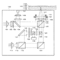
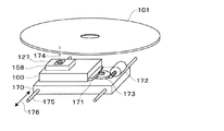
図1は、本発明の一実施形態に係るホログラム記録装置の光学ユニット100を表す模式図である。また、図2は光学ユニット100の一部を拡大した状態を表す模式図である。なお、図2では、内容の判りやすさのための、光学素子の一部の図示を省略している。
Hereinafter, embodiments of the present invention will be described with reference to the drawings.
FIG. 1 is a schematic diagram showing an
図1、2に示すように、ホログラム記録装置は、ホログラム記録媒体101への情報の記録、再生を行うものであり、光学ユニット100を備える。
光学ユニット100は、記録再生用光源111,コリメートレンズ112,偏光ビームスプリッタ113,ミラー121,ピンホール122,空間光変調器123,ミラー124,ダイクロイックミラー125,凹レンズ126,対物レンズ127,ファラデー素子131、132,偏光ビームスプリッタ133,撮像素子134,ミラー141,遮蔽板142,位相変調素子143,サーボ用光源151,コリメートレンズ152,グレーティング153,ビームスプリッタ154,集光用レンズ155,シリンドリカルレンズ156,受光素子157,サーボ用駆動ユニット158を有する。
As shown in FIGS. 1 and 2, the hologram recording apparatus records and reproduces information on a
The
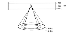
ホログラム記録媒体101は、保護層102,記録層103,グルーブ104,反射層105を有し、信号光と参照光による干渉縞を記録する記録媒体である。
保護層102は、記録層103を外界から保護するための層である。
記録層103は、この干渉縞を屈折率(あるいは、透過率)の変化として記録するものであり、光の強度に応じて屈折率(あるいは、透過率)の変化が行われる材料であれば、有機材料、無機材料の別を問うことなく利用可能である。
The
The
The
無機材料として、例えば、ニオブ酸リチウム(LiNbO3)のような電気光学効果によって露光量に応じ屈折率が変化するフォトリフラクティブ材料を用いることができる。
有機材料として、例えば、光重合型フォトポリマを用いることができる。光重合型フォトポリマは、その初期状態では、モノマがマトリクスポリマに均一に分散している。これに光が照射されると、露光部でモノマが重合する。そして、ポリマ化するにつれて周囲からモノマが移動してモノマの濃度が場所によって変化する。
以上のように、記録層103の屈折率(あるいは透過率)が露光量に応じて変化することで、参照光と信号光との干渉によって生じる干渉縞を屈折率(あるいは透過率)の変化としてホログラム記録媒体101に記録できる。
As the inorganic material, for example, a photorefractive material whose refractive index changes according to the exposure amount by an electro-optic effect such as lithium niobate (LiNbO3) can be used.
As the organic material, for example, a photopolymerization type photopolymer can be used. In the photopolymerization type photopolymer, in the initial state, monomers are uniformly dispersed in the matrix polymer. When this is irradiated with light, the monomer is polymerized at the exposed portion. As the polymer is formed, the monomer moves from the surroundings, and the concentration of the monomer changes depending on the location.
As described above, when the refractive index (or transmittance) of the
ホログラム記録媒体101は、図示しない駆動手段で移動、または回転され、空間光変調器123の像を多数のホログラムとして記録することができる。
ホログラム記録媒体101が移動することから、ホログラム記録媒体101上への記録・再生は移動方向に形成されたトラックに沿って行われる。
グルーブ104は、ホログラム記録媒体101へのトラッキング、フォーカス等のサーボ制御を行うために設けられる。即ち、ホログラム記録媒体101のトラックに沿ってグルーブ104が形成され、信号光の集光位置、集光深さをグルーブ104と対応するように制御することで、トラッキングサーボ、およびフォーカスサーボが行われる。
The
Since the
The
記録再生用光源111は、レーザ光源であり、例えば、波長405[nm]のレーザダイオード(LD)や波長532[nm]のNd-YAGレーザーを用いることができる。
コリメートレンズ112は、記録再生用光源111から照射されたレーザ光を平行光に変換する光学素子である。
偏光ビームスプリッタ113は、コリメートレンズ112から入射した平行光を信号光と参照光に分割する光学素子である。偏光ビームスプリッタ113からは、ミラー121に向かうs波の信号光とミラー141に向かうp波の参照光が出射される。
The recording / reproducing
The
The
ミラー121、124、141は、入射光を反射してその方向を変更する光学素子である。
ピンホール122は、信号光のビーム径を絞る光学素子である。
空間光変調器123は、信号光を空間的に(ここでは、2次元的に)変調して、データを重畳する光学素子である。空間光変調器123は、透過型の素子である透過型液晶素子を用いることができる。なお、空間光変調器に反射型の素子であるDMD (Digital micro mirror) や反射型液晶、GLV (Grating Light Value)素子を用いることが可能である。
The
The
The spatial
ダイクロイックミラー125は、記録再生に用いる光(記録再生用光源111からのレーザ光)とサーボに用いる光(サーボ用光源151からのレーザ光)とを同一の光路にするための光学素子である。ダイクロイックミラー125は、記録再生用光源111とサーボ用光源151とでレーザ光の波長が異なることに対応して、記録再生用光源111からの記録再生光を透過し、サーボ用光源151からのサーボ光を反射する。ダイクロイックミラー125は記録再生用の光は全透過し、サーボ用に用いる光は全反射するような薄膜処理がその表面に施されている。
凹レンズ126は、信号光の収束性を参照光と異ならせるためのレンズである。信号光のみが凹レンズ126を通過することで、信号光と参照光のホログラム記録媒体101での集光深さが異なってくる。
対物レンズ127は、信号光および参照光の双方をホログラム記録媒体101に集光するための光学素子である。
The
The
The
ファラデー素子131、132は、偏光面を回転するための光学素子である。ファラデー素子131に入射したs偏光は偏光面が45°回転され、ファラデー素子132で元のs偏光に戻される。
偏光ビームスプリッタ133は、ファラデー素子131から入射した偏光を透過し、ホログラム記録媒体101で反射されてファラデー素子132から戻ってきた戻り光(再生光)を反射するための光学素子である。これは、ファラデー素子131、132、と偏光ビームスプリッタ133との組み合わせにより実現される。
撮像素子134は、再生光の画像を入力するための素子である。例えば、CCD(電荷結合素子)やCMOS(相補型金属酸化物半導体)素子を用いることができる。
The
The
The
遮蔽板142は、参照光の一部を遮蔽して、記録光と重ならないようにするための光学素子である。
位相変調素子143は、参照光にランダム位相またはある一定の位相パターンを持たせるための光学素子であり、位相マスクといってもよい。位相変調素子143には、すりガラスやデフューザ、空間位相変調器を用いても良い。また、位相パターンを記録したホログラム素子を用いることも可能である。ホログラム素子からの再生によって位相パターンを有する光が発生する。
The shielding
The
サーボ用光源151は、トラッキングサーボ、フォーカスサーボ等のサーボ制御を行うための光源であり、記録再生用光源111とは波長の異なるレーザ光を出射する。サーボ用光源151は、例えば、レーザーダイオードであり、発振波長としてホログラム記録媒体101に対して感度が小さい、例えば、650nmを使用する。
コリメートレンズ152は、サーボ用光源151から照射されたレーザ光を平行光に変換する光学素子である。
グレーティング153は、コリメートレンズ152から出射されたレーザ光を3つのビームに分割するための光学素子であり、2枚の素子から構成される。サーボ制御のためにレーザ光の分割が行われる。
The
The
The grating 153 is an optical element for dividing the laser light emitted from the
ビームスプリッタ154は、グレーティング153から出射されたレーザ光を透過し、ホログラム記録媒体101から反射されて戻ってきた戻り光を反射するための光学素子である。
集光用レンズ155は、ビームスプリッタ154からの戻り光を受光素子157に集光するための光学素子である。
シリンドリカルレンズ156は、集光用レンズ155から出射されたレーザ光のビーム形状を円形から楕円形に変換するための光学素子である。
受光素子157は、戻り光を受光し、トラッキングサーボ制御のためのトラッキングエラー信号とフォーカスサーボ制御のためのフォーカスエラー信号を出力するための素子である。
サーボ用駆動ユニット158は、受光素子157の出力から生成されたトラッキングエラー信号およびフォーカスエラー信号により対物レンズ127を駆動し、トラッキング制御およびフォーカス制御を行うための駆動機構であり、駆動用のコイル161,162を有する。
The
The condensing
The
The
The
(ホログラム記録装置の動作)
以下、ホログラム記録装置の動作の概要を説明する。
A.記録時
記録時におけるホログラム記録装置の動作の概要を説明する。
記録再生用光源111から出射されたレーザ光がコリメートレンズ112によって平行光になり偏光ビームスプリッタ113によってs波の信号光とp波の参照光とに分割される。
(Operation of hologram recording device)
Hereinafter, an outline of the operation of the hologram recording apparatus will be described.
A. Recording Outline of the operation of the hologram recording apparatus during recording will be described.
The laser light emitted from the recording / reproducing
信号光はミラー121によって反射され,ピンホール122によって所望のビーム径にされ、空間光変調器123によって空間的に強度変調される。空間光変調器123で光変調されたレーザ光はファラデー素子131、偏光ビームスプリッタ133,ファラデー素子132を通過し、ミラー124によって反射され、ホログラム記録媒体101上での焦点を調節する凹レンズ126を通過する。
The signal light is reflected by the
また偏光ビームスプリッタ113を透過した参照光はミラー141で反射され、遮蔽板142によってビームの中心部分のみが遮断され所望のビームの形にされる。このため、ミラー124では反射されず信号光と同一の光路となる。
対物レンズ127が記録光と参照光とをホログラム記録媒体101上の略同一の箇所に集光することで、ホログラム記録媒体101上に干渉縞が形成される。この結果、空間光変調器123によって空間変調された情報をホログラム記録媒体101上にホログラムとして記録される。
Further, the reference light transmitted through the
The
ここでホログラム記録媒体101またはユニット100全体を平面的に移動(シフト)させ、信号光および参照光を略同一の箇所に入射させることで、空間変調によるデータをホログラムとしてホログラム記録媒体101に記録する。なお、このときに必要な移動量(シフト量)は位相変調素子143の位相パターンのピッチに依存する。
また、位相変調素子143またはユニット100全体をホログラム記録媒体101の表面に垂直な方向(奥行き方向)に移動(シフト)させ、信号光および参照光を入射させることで、空間変調によるデータを記録する。
なお、受光素子157からの出力信号から生成されたサーボ信号に基づきサーボ用駆動ユニット158が動作することで、トラッキングおよびフォーカスのずれが解消される。この詳細は後述する、
Here, the
Further, the
The
B.再生時
再生時におけるホログラム記録装置の動作の概要を説明する。
再生時には信号光を遮断し、参照光のみをホログラム記録媒体101に入射させる。
記録再生用光源111から出射し、偏光ビームスプリッタ113を透過した参照光がミラー141によって反射され、遮蔽板142によってビームの中心部分のみが遮断される。その後、参照光はダイクロイックミラー125を通過し、位相変調素子143によって記録時と同様の位相パターンを有する参照光となりホログラム記録媒体101に入射する。
B. At the time of reproduction An outline of the operation of the hologram recording apparatus at the time of reproduction will be described.
During reproduction, the signal light is blocked and only the reference light is incident on the
The reference light emitted from the recording / reproducing
記録時と同じ位相パターンを持った参照光がホログラム記録媒体101に入射することにより、ホログラム記録媒体101に記録されたホログラムから回折光(再生光)が発生する。
発生した再生光は信号光と逆の光路をたどり、対物レンズ127、凹レンズ126,ダイクロイックミラー125を透過して、ミラー124で反射される。
ミラー124で反射された再生光は、ファラデー素子132によって偏光方向が回転される。その結果、ファラデー素子132を出射した再生光は、偏光ビームスプリッタ133で反射され、撮像素子134によって空間光変調器123での空間的な2次元データに対応する電気信号に変換される。撮像素子134からの出力は、図示しない信号処理部によって2値化され、時系列2値化データに変換される。
When reference light having the same phase pattern as that at the time of recording enters the
The generated reproduction light follows an optical path opposite to that of the signal light, passes through the
The direction of polarization of the reproduction light reflected by the
ここでホログラム記録媒体101またはユニット100全体を平面的に移動(シフト)させ、ホログラム記録媒体101上で再生したい場所に参照光を入射させることによって所望のデータが再生される。
また、位相変調素子143またはユニット100全体をホログラム記録媒体101の表面に垂直な方向(奥行き方向)に移動(シフト)させることで奥行き方向に多重化されたデータを取り出すことができる。
Here, the
Further, the data multiplexed in the depth direction can be taken out by moving (shifting) the
[位相変調素子143によるホログラムの記録]
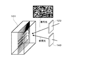
図3は、ホログラム記録装置により記録・再生されるホログラムを表す模式図である。
図3に示すように、空間光変調器123により空間的に変調された信号光と、位相変調素子143によってランダムな位相パターン又はある一定の規則性を持った位相パターンが付与された参照光とが干渉することで、ホログラム記録媒体101上にホログラムが記録される。記録時と一致する位相パターンを有する参照光をホログラム記録媒体101上に照射することで記録したホログラムが再生される(位相相関多重方式)。
[Recording of hologram by phase modulation element 143]
FIG. 3 is a schematic diagram showing a hologram recorded / reproduced by the hologram recording apparatus.
As shown in FIG. 3, the signal light spatially modulated by the spatial
ここで、ホログラム記録媒体101またはユニット100のいずれかまたは双方をホログラム記録媒体101の表面に沿ってシフトさせることで多重記録を行うことができる。このとき、参照光が位相パターンを有することから、このシフト量は微少で良い。
また、ホログラム記録媒体101と位相変調素子143の相対的な距離を変えることによって厚さ方向(表面に垂直な方向)の位相パターンを変えることができる。このため、ホログラム記録媒体101の厚さ方向への多重記録・再生が可能となる。
Here, multiple recording can be performed by shifting either or both of the
In addition, the phase pattern in the thickness direction (direction perpendicular to the surface) can be changed by changing the relative distance between the
多重記録する方向の順序は適宜に選択することが可能である。ホログラム記録媒体101の表面方向での多重記録の後に厚さ方向への多重記録することができる。この逆に、ホログラム記録媒体101の厚さ方向での多重記録の後に表面方向への多重記録することもできる。
The order of the multiplex recording directions can be selected as appropriate. Multiplex recording in the thickness direction can be performed after multiple recording in the surface direction of the
[焦点位置]
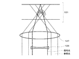
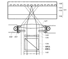
図1,2,では、凹レンズ126に信号光のみを通すことで、信号光の焦点をグルーブ104に、参照光の焦点をグルーブ104の手前に合わせている。
図4は、このときの干渉の状態を表す模式図である。
信号光、参照光の干渉によってホログラムが記録される。このとき生成されるホログラムは透過型格子である。再生時にも参照光によって回折光が再生され、その光が反射層105によって反射され、再生光として取り出される。
[Focus position]
In FIGS. 1 and 2, only the signal light is passed through the
FIG. 4 is a schematic diagram showing the state of interference at this time.
A hologram is recorded by interference of signal light and reference light. The hologram generated at this time is a transmission type grating. At the time of reproduction, the diffracted light is reproduced by the reference light, and the light is reflected by the
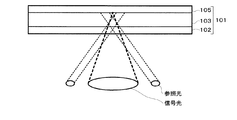
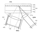
図5は、凹レンズ126に換えて凸レンズ126aを用いることで、信号光の焦点をグルーブ104の手前に、参照光の焦点をグルーブ104に合わせたときの干渉の状態を表す模式図である。
このときには参照光が反射層105で反射した成分と信号光との干渉によってホログラムが記録され、再生時と同様に参照光の反射成分から回折光が発生する。
この他にも、信号光と参照光の両方ともグルーブ104の手前に焦点を合わせたり、両方ともグルーブ104の後に焦点を合わせたりするなどの組み合わせが考えられる。
図1,2では参照光を信号光の手前に結ばせるために信号光に凹レンズ126を入れているが、これに換えて参照光側に凸レンズを入れてもよい。また、図5では信号光に凸レンズ126aを入れているが、これに換えて参照光に凹レンズを入れることもできる。
FIG. 5 is a schematic diagram showing the state of interference when the convex lens 126 a is used instead of the
At this time, a hologram is recorded by interference between the component of the reference light reflected by the
Other combinations such as focusing both the signal light and the reference light in front of the
In FIGS. 1 and 2, the
[参照光の形状について]
図6は、図1,2における参照光の形状を表す模式図である。信号光の回りを囲うように参照光が入射されている。
これに換えて、図7のように信号光に対して両脇から参照光を2本入射させることができる。また両脇からではなく片方のみから参照光を入射させることもできる。参照光が3本や4本であっても良い。
[Reference beam shape]
FIG. 6 is a schematic diagram showing the shape of the reference light in FIGS. Reference light is incident so as to surround the signal light.
Instead, two reference lights can be incident on the signal light from both sides as shown in FIG. Further, the reference light can be incident only from one side, not from both sides. There may be three or four reference beams.
[サーボ機構について]
以下、ホログラム記録装置のサーボ動作について説明する。
サーボ用光源151から出射したレーザービーム(サーボ用ビーム)は、コリメートレンズ152で平行光とされ、グレーティング153で複数に分けられ、ビームスプリッタ154に入射する。サーボ用ビームはビームスプリッタ154を通過し、ダイクロイックミラー125で反射される。ダイクロイックミラー125で反射されたサーボ用ビームは対物レンズ127で絞られてホログラム記録媒体101に照射される。
[Servo mechanism]
Hereinafter, the servo operation of the hologram recording apparatus will be described.
The laser beam (servo beam) emitted from the
ホログラム記録媒体101の反射層105で反射されたサーボ用ビームは対物レンズ127を通り、ダイクロイックミラー125で反射されてビームスプリッタ154に入射する。このサーボ用ビームは、ビームスプリッタ154で反射され、集光用レンズ155で絞られた後にシリンドリカルレンズ156で非点収差を発生させて受光素子(フォトディテクタ)157に入射する。
The servo beam reflected by the
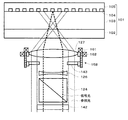
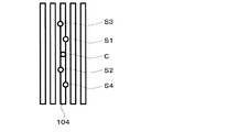
図8は、ホログラム記録媒体101に照射されるサーボ用ビームとグルーブ104との関係を表す模式図である。
本図に示すように、サーボ用ビームは、グレーティング153で分割され、センタービームC、およびこれを挟む複数のビームS1〜S4としてグルーブ104に照射される。グレーティング153は、2枚で構成され、1枚でS1とS2を、もう1枚でS3とS4のビームを生成する。
これらのサーボ用ビームS1〜S4は、例えばグルーブ104に半分だけかかるように傾けて配置される。ビームS1、S2とビームS3、S4は互いに反対方向に傾けられる。
なお、サーボ用ビームの位置は記録再生用ビームの中央に配置する必要はなく、どこにあっても良い。
FIG. 8 is a schematic diagram showing the relationship between the servo beam and the
As shown in the figure, the servo beam is divided by a
These servo beams S <b> 1 to S <b> 4 are disposed so as to be inclined so that, for example, only half of the
The position of the servo beam does not have to be arranged at the center of the recording / reproducing beam, and may be anywhere.
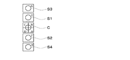
図9は、受光素子157の構成の詳細を表す模式図である。本図に示すように、受光素子157は、8つの素子A〜Hで構成される。素子G上にビームS3が、素子E上にビームS1が、素子A〜D上にビームCが、素子F上にビームS2が、素子H上にビームS4が入射する。
フォーカスサーボエラー信号とトラッキングサーボエラー信号は、8つの素子A〜Hの出力PA〜PHより以下の演算により生成される。
フォーカスエラー信号(Focus error):(PA+PC)-(PB+PD)
トラッキングエラー信号(Tracking error):PE-PF
これらのエラー信号に基づいて、サーボ用駆動ユニット158のコイル161,162が対物レンズ127を駆動することで、フォーカスサーボ、トラッキングサーボが行われる。
FIG. 9 is a schematic diagram illustrating details of the configuration of the
The focus servo error signal and the tracking servo error signal are generated from the outputs PA to PH of the eight elements A to H by the following calculation.
Focus error signal: (PA + PC)-(PB + PD)
Tracking error signal: PE-PF
Based on these error signals, the
図10は、図1,2に示す光学ユニット100を駆動する駆動機構を表す模式図である。
本図に示すように、光学ユニット100は、送りステージ170の上に配置され、片方の端にギヤ171が取り付けられている。送りステージ170上の他方にはモーター172とその回転を減速するギヤ173が取り付けられており、モーター172とギヤ173とギヤ171が噛み合い光学ユニット100が対物レンズ127を通る光軸174を中心として回転される。
送りステージ170にはシャフト175が取り付けられており、ホログラム記録媒体101の内外周方向(矢印176の方向)への移動がモーター(図示せず)で可能なようにされている。これら光学ユニット100の上にホログラム記録媒体101が配置され、スピンドルモーター(図示せず)によって回転させられる。
その結果、ホログラム記録媒体101上の適宜の位置でホログラムを記録、再生できる。
FIG. 10 is a schematic diagram showing a drive mechanism that drives the
As shown in the figure, the
A
As a result, the hologram can be recorded and reproduced at an appropriate position on the
[位相変調素子(デフューザ)143の位置制御]
ホログラム記録媒体101に対する位相変調素子143の位置制御機構につき説明する。
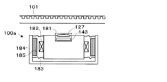
図11は、位相変調素子143の位置制御機構を表す模式図である。
光学ユニット100aに対物レンズ127と位相変調素子143とを有する対物レンズユニット181が配置される。光学ユニット100aの両側にコイル182が取り付けられ、サスペンション183でキャリッジ184に取り付けられている。
コイル182の対抗側にはキャリッジ184に取り付けられたマグネット185が配置される。
コイル182に電流を流すと、マグネット185からの磁界により電磁力が生じ、光学ユニット100aが上下方向に移動する。
ホログラム記録媒体101は回転しているため面ぶれ等により対物レンズ127との距離が変化する。このため、フォーカスエラー信号に基づきコイル182に電流を流して、光学ユニット100a全体を上下方向に動かして、フォーカスサーボをかける。
[Position control of phase modulator (diffuser) 143]
A position control mechanism of the
FIG. 11 is a schematic diagram illustrating a position control mechanism of the
An
A
When a current is passed through the
Since the
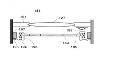
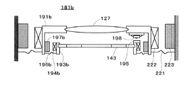
図12は、対物レンズユニット181の内部構成を表す模式図である。
対物レンズ127がホルダ191に取り付けられ、光学ユニット100aの筐体に固定されている。対物レンズ127の下にはホルダ193に位相変調素子143が取り付けられ、その両側にコイル194と、片方のコイル194の上に反射板195が取り付けられている。
ホルダ193はサスペンション196により対物レンズユニット181の筐体に取り付けられ、位相変調素子143が上下方向に移動できる。又、コイル194の対抗側にはマグネット197が光学ユニット100aの筐体に取り付けられている。反射板195の上部には位置検出器198が取り付けられており、対物レンズ127に対する位相変調素子143の上下方向の位置が検出できる。
FIG. 12 is a schematic diagram showing the internal configuration of the
The
The
図13は、位置検出器198の詳細な構成を表す模式図である。
位置検出器198は、LED201と位置検出素子202が同一のパッケージに入って構成される。LED201から出射された光が反射板195で反射されて位置検出素子202に入射する。
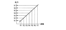
図14は、位置検出器198の特性を表すグラフである。
本図に示すように、位置検出器198から出力される出力電圧は、位置検出器198と反射板195との距離に対してリニアに変化する。
FIG. 13 is a schematic diagram illustrating a detailed configuration of the
The
FIG. 14 is a graph showing the characteristics of the
As shown in the figure, the output voltage output from the
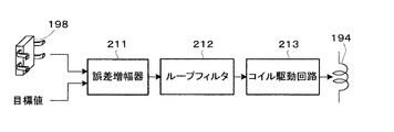
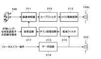
図15は、位相変調素子143の位置を制御する制御系を表すブロック図である。
例えば、位相変調素子143と対物レンズ127の距離がP1の位置にあり、ここからP2に移動する場合、位置検出器198からの出力電圧V1が誤差増幅器211の入力端子に入力される。
誤差増幅器211のもう一方の入力端子には目標値の電圧V2が入力され、ここでV2とV1の誤差が増幅される。この出力は次のループフィルタ212でサーボ系として最適な特性とされコイル駆動回路213によりコイル194に電流を流す。
FIG. 15 is a block diagram illustrating a control system that controls the position of the
For example, when the distance between the
A target value voltage V2 is input to the other input terminal of the
コイル194の電流とマグネット197の磁界によりコイル194側に電磁力が働き、例えば誤差増幅器211の出力電圧の極性が正ならばコイル194に正極性の電流が流れ、位相変調素子143は遠ざかる方向に動く。それに伴って位置検出器198の出力電圧は目標電圧V2に近づいて行くため、誤差増幅器211の出力電圧が減少して行き、P2の位置で停止する。
位相変調素子143と対物レンズ127の距離がP4の位置にあり、ここからP3に移動する場合は、誤差増幅器211の出力電圧の極性が負となるので、コイル194には負極性の電流が流れ、位相変調素子143は対物レンズ127に近づく方向に動く。それに伴って位置検出器198の出力はV3に近づいて行くため、誤差増幅器211の出力電圧が減少して行き、P3の位置で停止する。
Electromagnetic force acts on the
When the distance between the
以上のように制御回路はネガティブフィードバックを構成しているので、目標値として入力した電圧V2と、位置検出器198の出力電圧が等しくなる位置にいつも制御される。以上のように目標値をV3、V4・・・と入力すればそれぞれに対応して位相変調素子143と対物レンズ127の距離関係をP3、P4・・・に位置決めすることができ、その距離をいつも一定に維持することができる。
As described above, since the control circuit constitutes negative feedback, the control circuit is always controlled to a position where the voltage V2 input as the target value is equal to the output voltage of the
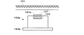
図16は、位相変調素子143の位置制御機構の他の実施例を表す模式図である。対物レンズユニット181bを備える光学ユニット100bがキャリッジ184bに固定されている。
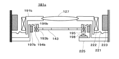
図17は光学ユニット100bに配置される対物レンズユニット181bを表す模式図である。
図17に示すように、ホルダ193bに位相変調素子143が取り付けられ、その両側にコイル194bと、一方のコイル194bの上に反射板195が取り付けられている。更にホルダ193bはサスペンション196bによりホルダ191bに取り付けられており、位相変調素子143を上下方向に移動できる。
又、コイル194bの対抗側には、ホルダ191bに取り付けられたマグネット197bが配置される。反射板195の上部には位置検出器198が取り付けられており、対物レンズ127に対する位相変調素子143の上下方向の位置が検出できる。既述のように、対物レンズ127と位相変調素子143との距離は制御系により一定に制御される。
対物レンズ127はホルダ191bに取り付けられ、光学ユニット100bの筐体にサスペンション221で固定されている。ホルダ191bにはコイル222が取り付けられ、その対抗側にマグネット223が対物レンズユニット181bの筐体に取り付けられている。
FIG. 16 is a schematic diagram showing another embodiment of the position control mechanism of the
FIG. 17 is a schematic diagram showing the
As shown in FIG. 17, a
A
The
回転しているディスクの面ぶれ等によりホログラム記録媒体101と対物レンズ127との距離が変化する。このため、フォーカスエラー信号に基づきコイル222に電流を流し、同じホルダ191bに取り付けられた対物レンズ127と位相変調素子143とが一緒に上下・左右方向に動き、フォーカスサーボ・トラッキングサーボがかけられる。すなわち、この例では光学ユニット100bは固定され、光学ユニット100b上に配置してあるフォーカスサーボ用と位相変調素子143用のアクチュエータが動作する。
The distance between the
図18は、位相変調素子143の位置制御機構の他の実施例に係る対物レンズユニット181cを表す模式図である。
図18に示すように、ホルダ193bに位相変調素子143が取り付けられる。更にホルダ193bはサスペンション196bによりホルダ225に取り付けられる。又、コイル194bの対抗側にはマグネット197bがホルダ225に取り付けられ、このホルダ225は対物レンズユニット181cの筐体に固定されている。
FIG. 18 is a schematic diagram illustrating an
As shown in FIG. 18, the
反射板195の下部には位置検出器198が取り付けられており、対物レンズユニット181cに対する位相変調素子143の上下方向の位置が検出できるようにされている。
この場合は位置検出器198がホルダ225に取り付けられているので、対物レンズユニット181cと位相変調素子143の距離が制御される。
対物レンズ127はホルダ191bに取り付けられ、対物レンズユニット181cの筐体にサスペンション221で固定されている。
ホルダ191bにはコイル222が取り付けられ、その対抗側にマグネット223が対物レンズユニット181cの筐体に取り付けられている。
A
In this case, since the
The
A
回転しているディスクの面ぶれ等によりホログラム記録媒体101と対物レンズ127との距離が変化する。このため、フォーカスエラー信号に基づきコイル222に電流を流し、対物レンズ127が上下方向に動き、フォーカスサーボがかけられる。
すなわち、この例では対物レンズユニット181cは固定されており、位相変調素子143とフォーカスサーボ用のアクチュエータ(コイル222)がそれぞれ単独に動作する。
The distance between the
That is, in this example, the
この例はホログラム記録媒体101の厚み方向に対して位相変調素子143の位置トレランスが広い場合に有利である。本方式においてユニット100全体を動かしてサーボをかけると動作が遅くなるように思えるが、ホログラム記録の場合通常のCDやDVDと比べると線速度は数10〜数100分の1であるためサーボの帯域としては非常に小さいためさほど問題にならない。
This example is advantageous when the position tolerance of the
以上のように、対物レンズユニット181cにおいて、対物レンズ127はフォーカスサーボ回路により、ホログラム記録媒体101との距離が一定になるように制御され、位相変調素子143は目標位置となるように制御されている。
これら両者は別々に制御されているが、例えば、フォーカスサーボにより対物レンズ127が移動した場合には位相変調素子143の位置も同じ量だけ移動するのがより良い。すなわち、両者が同期して動作するようにしたほうが良い。
As described above, in the
Both of these are controlled separately. For example, when the
図19は、対物レンズ127および位相変調素子143の位置を制御する制御系を表すブロック図である。
図19で、コイル222にはフォーカスエラー信号に基づきサーボ回路214により電流が流され、動作している。
コイル222に流れる電流、あるいは電圧の直流成分は、対物レンズ127の移動距離に比例するため、低域フィルター215により直流成分を取り出し、ゲイン調整回路216で対物レンズ127の移動量と同じ移動量となるようにゲイン調整され、加算回路217に入力される。この入力量は対物レンズ127の移動量に相当する。加算回路217のもう一方には、対物レンズ127と位相変調素子143間の距離の目標値が入力される。この両者が加算され、誤差増幅器211に入力される。
すでに説明したように、位相変調素子143は、誤差増幅器211、ループフィルタ212,コイル駆動回路213によりこの目標値で設定した位置となるよう位置が制御される。すなわち、位相変調素子143は対物レンズ127に対して目標値で設定した距離を保ちながら、対物レンズ127に同期して移動する。
FIG. 19 is a block diagram illustrating a control system that controls the positions of the
In FIG. 19, the
Since the direct current component of the current or voltage flowing through the
As already described, the position of the
[対物レンズ、位相変調素子143の駆動手段]
以上では、対物レンズ127や位相変調素子143をコイル161,162等で電磁力により駆動させている。これに対して、他の手段、例えば、機械的な手段により対物レンズ127や位相変調素子143を駆動することも可能である。
図20は、対物レンズ127や位相変調素子143を機械的な手段で駆動するものであり、図2と対応する。
ここでは、ラック231とピニオン232の組み合わせで、対物レンズ127および位相変調素子143が上下に移動する。即ち、ピニオン232を図示しないモータで駆動することで、対物レンズ127および位相変調素子143を駆動できる。
[Objective lens, means for driving phase modulation element 143]
In the above, the
FIG. 20 corresponds to FIG. 2 in which the
Here, the
[信号光と参照光の別入射]
今までは、信号光と参照光を同一の光路からホログラム記録媒体101に入射させていたが、信号光と参照光を別々の光路から入射させてもよい。
図21は、信号光と参照光が別々の光路で入射するホログラム記録装置の光学ユニット100sを表す模式図である。
信号光が空間光変調器123によって空間強度変調され、対物レンズ127aによってホログラム記録媒体101に入射される。また参照光が位相変調素子143によって位相変調され対物レンズ127bによってホログラム記録媒体101に入射する。
サーボ系メカニカルユニット241は参照光にサーボをかける。また奥行き方向の多重記録は奥行き方向多重用メカニカル機構2420によって位相変調素子143がシフトすることによって行われる。
[Separate incidence of signal light and reference light]
Up to now, the signal light and the reference light have been incident on the
FIG. 21 is a schematic diagram illustrating the
The signal light is spatially modulated by the spatial
The servo system
100 光学ユニット
101 ホログラム記録媒体
102 保護層
103 記録層
104 グルーブ
105 反射層
111 記録再生用光源
112 コリメートレンズ
113 偏光ビームスプリッタ
121 ミラー
122 ピンホール
123 空間光変調器
124 ミラー
125 ダイクロイックミラー
126 凹レンズ
127 対物レンズ
131 ファラデー素子
132、133 偏光ビームスプリッタ
134 撮像素子
141 ミラー
142 遮蔽板
143 位相変調素子
151 サーボ用光源
152 コリメートレンズ
153 グレーティング
154 ビームスプリッタ
155 集光用レンズ
156 シリンドリカルレンズ
157 受光素子
158 サーボ用駆動ユニット
161,162 コイル
DESCRIPTION OF
Claims (8)
前記レーザ光源から出射されたレーザ光を信号光と参照光に分岐する光分岐素子と、
前記光分岐素子で分岐された信号光を変調する光変調素子と、
前記光分岐素子で分岐された参照光を位相変調する位相変調素子と、
前記光変調素子で変調された信号光および前記位相変調素子で位相変調された参照光をホログラム記録媒体の略同一箇所に集光する光学系と、
前記位相変調素子と前記ホログラム記録媒体との距離を制御する距離制御機構と、
を具備することを特徴とするホログラム記録装置。 A laser light source for emitting laser light;
A light branching element for branching the laser light emitted from the laser light source into signal light and reference light;
An optical modulation element that modulates the signal light branched by the optical branching element;
A phase modulation element that phase-modulates the reference light branched by the light branching element;
An optical system that focuses the signal light modulated by the light modulation element and the reference light phase-modulated by the phase modulation element at substantially the same location of the hologram recording medium;
A distance control mechanism for controlling the distance between the phase modulation element and the hologram recording medium;
A holographic recording apparatus comprising:
ことを特徴とする請求項1記載のホログラム記録装置。 The hologram recording apparatus according to claim 1, wherein the optical system includes an objective lens that focuses both the signal light and the reference light on the hologram recording medium.
ことを特徴とする請求項2記載のホログラム記録装置。 The hologram recording apparatus according to claim 2, wherein the optical system includes a lens that allows only one of the signal light and the reference light to pass therethrough.
ことを特徴とする請求項1記載のホログラム記録装置。 The optical system includes: a first objective lens that condenses the signal light on the hologram recording medium; and a second objective lens that condenses the reference light on the hologram recording medium. The hologram recording apparatus according to claim 1.
前記レーザ光源から出射されたレーザ光を参照光として位相変調する位相変調素子と、
前記位相変調素子で位相変調された参照光をホログラム記録媒体に集光する光学系と、
前記位相変調素子と前記ホログラム記録媒体との距離を制御する距離制御機構と、
を具備することを特徴とするホログラム再生装置。 A laser light source for emitting laser light;
A phase modulation element that phase-modulates laser light emitted from the laser light source as reference light;
An optical system for focusing the reference light phase-modulated by the phase modulation element on a hologram recording medium;
A distance control mechanism for controlling the distance between the phase modulation element and the hologram recording medium;
A hologram reproducing apparatus comprising:
前記光分岐ステップで分岐された信号光を光変調素子で変調する光変調ステップと、
前記光分岐ステップで分岐された参照光を位相変調素子で位相変調する位相変調ステップと、
前記光変調ステップで変調された信号光および前記位相変調ステップで位相変調された参照光をホログラム記録媒体の略同一箇所に集光する集光ステップと、
前記位相変調素子と前記ホログラム記録媒体との距離を制御する距離制御ステップと、
を具備することを特徴とするホログラム記録方法。 A light branching step for branching laser light emitted from the laser light source into signal light and reference light;
An optical modulation step of modulating the signal light branched in the optical branching step with an optical modulation element;
A phase modulation step of phase-modulating the reference light branched in the light branching step with a phase modulation element;
A condensing step of condensing the signal light modulated in the light modulation step and the reference light phase-modulated in the phase modulation step at substantially the same location of the hologram recording medium;
A distance control step for controlling a distance between the phase modulation element and the hologram recording medium;
A hologram recording method comprising:
前記位相変調ステップで位相変調された参照光をホログラム記録媒体に集光する集光ステップと、
前記位相変調素子と前記ホログラム記録媒体との距離を制御する距離制御ステップと、
を具備することを特徴とするホログラム再生方法。 A phase modulation step of performing phase modulation with a phase modulation element using laser light emitted from a laser light source as reference light;
A condensing step of condensing the reference light phase-modulated in the phase modulation step onto a hologram recording medium;
A distance control step for controlling a distance between the phase modulation element and the hologram recording medium;
A hologram reproducing method comprising:
前記光分岐ステップで分岐された信号光を光変調素子で変調する光変調ステップと、
前記光分岐ステップで分岐された参照光を位相変調素子で位相変調する位相変調ステップと、
前記光変調ステップで変調された信号光および前記位相変調ステップで位相変調された参照光をホログラム記録媒体の略同一箇所に集光する集光ステップと、
前記位相変調素子と前記ホログラム記録媒体との距離を制御する距離制御ステップと、
を有するホログラム記録方法によってデータが記録されていることを特徴とするホログラム記録媒体。 A light branching step for branching laser light emitted from the laser light source into signal light and reference light;
An optical modulation step of modulating the signal light branched in the optical branching step with an optical modulation element;
A phase modulation step of phase-modulating the reference light branched in the light branching step with a phase modulation element;
A condensing step of condensing the signal light modulated in the light modulation step and the reference light phase-modulated in the phase modulation step at substantially the same location of the hologram recording medium;
A distance control step for controlling a distance between the phase modulation element and the hologram recording medium;
A hologram recording medium, wherein data is recorded by a hologram recording method comprising:
Priority Applications (6)
| Application Number | Priority Date | Filing Date | Title |
|---|---|---|---|
| JP2004102712A JP2005293630A (en) | 2004-03-31 | 2004-03-31 | Hologram recording apparatus, hologram reproducing apparatus, hologram recording method, hologram reproducing method, and hologram recording medium |
| EP05727289A EP1732068A4 (en) | 2004-03-31 | 2005-03-25 | HOLOGRAM RECORDING DEVICE, HOLOGRAM REPRODUCING DEVICE, HOLOGRAM RECORDING METHOD, HOLOGRAM REPRODUCING METHOD, AND HOLOGRAM RECORDING MEDIUM |
| PCT/JP2005/006433 WO2005096281A1 (en) | 2004-03-31 | 2005-03-25 | Hologram recording device, hologram reproduction device, hologram recording method, hologram reproduction method, and hologram recording medium |
| KR1020067017611A KR20070006758A (en) | 2004-03-31 | 2005-03-25 | Hologram recording device, hologram reproducing device, hologram recording method, hologram reproducing method, and hologram recording medium |
| CNA2005800089673A CN1934626A (en) | 2004-03-31 | 2005-03-25 | Hologram recording device, hologram reproduction device, hologram recording method, hologram reproduction method, and hologram recording medium |
| US10/593,564 US20070146838A1 (en) | 2004-03-31 | 2005-03-25 | Hologram recording device, hologram reproductive device, hologram recording method, hologram reproduction method, and hologram recording medium |
Applications Claiming Priority (1)
| Application Number | Priority Date | Filing Date | Title |
|---|---|---|---|
| JP2004102712A JP2005293630A (en) | 2004-03-31 | 2004-03-31 | Hologram recording apparatus, hologram reproducing apparatus, hologram recording method, hologram reproducing method, and hologram recording medium |
Publications (1)
| Publication Number | Publication Date |
|---|---|
| JP2005293630A true JP2005293630A (en) | 2005-10-20 |
Family
ID=35064025
Family Applications (1)
| Application Number | Title | Priority Date | Filing Date |
|---|---|---|---|
| JP2004102712A Pending JP2005293630A (en) | 2004-03-31 | 2004-03-31 | Hologram recording apparatus, hologram reproducing apparatus, hologram recording method, hologram reproducing method, and hologram recording medium |
Country Status (6)
| Country | Link |
|---|---|
| US (1) | US20070146838A1 (en) |
| EP (1) | EP1732068A4 (en) |
| JP (1) | JP2005293630A (en) |
| KR (1) | KR20070006758A (en) |
| CN (1) | CN1934626A (en) |
| WO (1) | WO2005096281A1 (en) |
Cited By (17)
| Publication number | Priority date | Publication date | Assignee | Title |
|---|---|---|---|---|
| WO2007043451A1 (en) * | 2005-10-05 | 2007-04-19 | Pioneer Corporation | Hologram recording/reproducing system |
| JP2007172806A (en) * | 2005-12-21 | 2007-07-05 | Ind Technol Res Inst | Holographic storage and playback system and method using servo |
| JP2007184070A (en) * | 2005-12-30 | 2007-07-19 | Ind Technol Res Inst | System and method for recording and reproducing holographic interferogram with optical servo |
| WO2007102570A1 (en) * | 2006-03-09 | 2007-09-13 | Sharp Kabushiki Kaisha | Information recorder and information reproducer |
| JP2007280583A (en) * | 2006-04-06 | 2007-10-25 | Daewoo Electronics Corp | Optical information processing apparatus, and optical information recording and reproducing method using the same |
| JP2008027518A (en) * | 2006-07-21 | 2008-02-07 | Fujifilm Corp | Optical recording method, optical recording apparatus, optical recording medium, optical reproducing method, and optical reproducing apparatus |
| JP2008107829A (en) * | 2006-10-13 | 2008-05-08 | Thomson Licensing | Holographic recording medium reproducing and / or recording device |
| JP2008130225A (en) * | 2006-11-24 | 2008-06-05 | Samsung Electronics Co Ltd | Holographic information recording / reproducing apparatus, recording / reproducing method, and holographic information recording medium |
| JP2008140472A (en) * | 2006-12-01 | 2008-06-19 | Fuji Xerox Co Ltd | Optical recorder, optical recording method, recording medium and reproducing method |
| JP2008226433A (en) * | 2007-03-09 | 2008-09-25 | Hitachi Ltd | Optical pickup, optical information reproducing apparatus and optical information recording / reproducing apparatus using the same |
| JP2008226434A (en) * | 2007-03-09 | 2008-09-25 | Hitachi Ltd | Optical pickup, optical information recording / reproducing apparatus, and optical information recording / reproducing method |
| JP2008269771A (en) * | 2007-04-19 | 2008-11-06 | Thomson Licensing | Apparatus for reading from and / or writing to holographic storage media |
| JPWO2007026588A1 (en) * | 2005-08-30 | 2009-03-26 | パイオニア株式会社 | Optical pickup device and hologram recording / reproducing system |
| JP2010055708A (en) * | 2008-08-29 | 2010-03-11 | Panasonic Corp | Recording and reproducing device |
| JP2011129169A (en) * | 2009-12-15 | 2011-06-30 | Hitachi Consumer Electronics Co Ltd | Optical information recording/reproducing apparatus and optical information reproducing apparatus |
| JP5450649B2 (en) * | 2009-11-24 | 2014-03-26 | 株式会社東芝 | Information storage device |
| WO2016020994A1 (en) * | 2014-08-06 | 2016-02-11 | 株式会社日立製作所 | Otical information recording device and optical information reproduction device |
Families Citing this family (11)
| Publication number | Priority date | Publication date | Assignee | Title |
|---|---|---|---|---|
| JP2008108359A (en) | 2006-10-25 | 2008-05-08 | Funai Electric Co Ltd | Optical information recording device and optical information reproducing device |
| JP4297944B2 (en) * | 2007-02-08 | 2009-07-15 | シャープ株式会社 | Information recording apparatus and information reproducing apparatus |
| FR2921501B1 (en) * | 2007-09-24 | 2009-12-18 | Commissariat Energie Atomique | DEVICE FOR RECORDING AND READING DATA ON A HOLOGRAPHIC STORAGE MEDIUM |
| WO2009138973A2 (en) * | 2008-05-14 | 2009-11-19 | Dublin Institute Of Technology | A holographic recording medium |
| JP2010231850A (en) * | 2009-03-27 | 2010-10-14 | Sony Corp | Light irradiation device and control method |
| EP2290474A1 (en) * | 2009-08-14 | 2011-03-02 | Thomson Licensing | Tilt compensation for a holographic storage system |
| US9291997B2 (en) | 2012-05-17 | 2016-03-22 | Samsung Electronics Co., Ltd. | High speed hologram recording apparatus and method |
| JP2014049162A (en) * | 2012-08-31 | 2014-03-17 | Hitachi-Lg Data Storage Inc | Optical information recorder |
| KR101979674B1 (en) * | 2013-06-20 | 2019-05-17 | 한국전자통신연구원 | Method and apparatus for steering of reference beam in hologram printer |
| CN107767887A (en) * | 2017-12-06 | 2018-03-06 | 苏州盤谷信息光学有限公司 | A kind of holographic memory device based on dichroic reflective layer |
| KR102111639B1 (en) * | 2018-06-29 | 2020-05-15 | 광운대학교 산학협력단 | Manufacture System of Large Scale Holographic Transparent Screen Using Shift Multiplexing and Manufacturing Method of The Same |
Family Cites Families (3)
| Publication number | Priority date | Publication date | Assignee | Title |
|---|---|---|---|---|
| US5719691A (en) * | 1995-05-05 | 1998-02-17 | Lucent Technologies Inc. | Phase correlation multiplex holography |
| DE69941481D1 (en) * | 1998-02-27 | 2009-11-12 | Optware Corp | METHOD AND DEVICE FOR OPTICAL INFORMATION, METHOD AND DEVICE FOR REPRODUCING OPTICAL INFORMATION, RECORDING DEVICE, PLAYING OPTICAL INFORMATION AND OPTICAL INFORMATION RECORDING MEDIUM |
| JP3393064B2 (en) * | 1998-02-27 | 2003-04-07 | 株式会社オプトウエア | Optical information recording medium |
-
2004
- 2004-03-31 JP JP2004102712A patent/JP2005293630A/en active Pending
-
2005
- 2005-03-25 US US10/593,564 patent/US20070146838A1/en not_active Abandoned
- 2005-03-25 WO PCT/JP2005/006433 patent/WO2005096281A1/en not_active Ceased
- 2005-03-25 KR KR1020067017611A patent/KR20070006758A/en not_active Withdrawn
- 2005-03-25 CN CNA2005800089673A patent/CN1934626A/en active Pending
- 2005-03-25 EP EP05727289A patent/EP1732068A4/en not_active Withdrawn
Cited By (23)
| Publication number | Priority date | Publication date | Assignee | Title |
|---|---|---|---|---|
| JPWO2007026588A1 (en) * | 2005-08-30 | 2009-03-26 | パイオニア株式会社 | Optical pickup device and hologram recording / reproducing system |
| WO2007043451A1 (en) * | 2005-10-05 | 2007-04-19 | Pioneer Corporation | Hologram recording/reproducing system |
| JP2007172806A (en) * | 2005-12-21 | 2007-07-05 | Ind Technol Res Inst | Holographic storage and playback system and method using servo |
| US7859970B2 (en) | 2005-12-21 | 2010-12-28 | Industrial Technology Research Institute | Holographic storage and reproduction system and method with servo |
| JP2007184070A (en) * | 2005-12-30 | 2007-07-19 | Ind Technol Res Inst | System and method for recording and reproducing holographic interferogram with optical servo |
| WO2007102570A1 (en) * | 2006-03-09 | 2007-09-13 | Sharp Kabushiki Kaisha | Information recorder and information reproducer |
| JP2007280583A (en) * | 2006-04-06 | 2007-10-25 | Daewoo Electronics Corp | Optical information processing apparatus, and optical information recording and reproducing method using the same |
| JP2008027518A (en) * | 2006-07-21 | 2008-02-07 | Fujifilm Corp | Optical recording method, optical recording apparatus, optical recording medium, optical reproducing method, and optical reproducing apparatus |
| US7835249B2 (en) | 2006-07-21 | 2010-11-16 | Fujifilm Corporation | Optical recording method, optical recording apparatus, optical recording medium, optical reproducing method, and optical reproducing apparatus |
| US8289597B2 (en) | 2006-10-13 | 2012-10-16 | Thomson Licensing | Apparatus for reading from and/or writing to holographic storage media |
| JP2008107829A (en) * | 2006-10-13 | 2008-05-08 | Thomson Licensing | Holographic recording medium reproducing and / or recording device |
| JP2008130225A (en) * | 2006-11-24 | 2008-06-05 | Samsung Electronics Co Ltd | Holographic information recording / reproducing apparatus, recording / reproducing method, and holographic information recording medium |
| US8270278B2 (en) | 2006-12-01 | 2012-09-18 | Fuji Xerox Co., Ltd. | Optical recording apparatus, optical recording method, recording medium, and reproducing method |
| JP2008140472A (en) * | 2006-12-01 | 2008-06-19 | Fuji Xerox Co Ltd | Optical recorder, optical recording method, recording medium and reproducing method |
| JP2008226434A (en) * | 2007-03-09 | 2008-09-25 | Hitachi Ltd | Optical pickup, optical information recording / reproducing apparatus, and optical information recording / reproducing method |
| JP2008226433A (en) * | 2007-03-09 | 2008-09-25 | Hitachi Ltd | Optical pickup, optical information reproducing apparatus and optical information recording / reproducing apparatus using the same |
| JP2008269771A (en) * | 2007-04-19 | 2008-11-06 | Thomson Licensing | Apparatus for reading from and / or writing to holographic storage media |
| US8284469B2 (en) | 2007-04-19 | 2012-10-09 | Thomson Licensing | Apparatus for reading from and/or writing to holographic storage media |
| JP2010055708A (en) * | 2008-08-29 | 2010-03-11 | Panasonic Corp | Recording and reproducing device |
| JP5450649B2 (en) * | 2009-11-24 | 2014-03-26 | 株式会社東芝 | Information storage device |
| JP2011129169A (en) * | 2009-12-15 | 2011-06-30 | Hitachi Consumer Electronics Co Ltd | Optical information recording/reproducing apparatus and optical information reproducing apparatus |
| WO2016020994A1 (en) * | 2014-08-06 | 2016-02-11 | 株式会社日立製作所 | Otical information recording device and optical information reproduction device |
| JPWO2016020994A1 (en) * | 2014-08-06 | 2017-04-27 | 株式会社日立製作所 | Optical information recording apparatus and optical information reproducing apparatus |
Also Published As
| Publication number | Publication date |
|---|---|
| US20070146838A1 (en) | 2007-06-28 |
| KR20070006758A (en) | 2007-01-11 |
| CN1934626A (en) | 2007-03-21 |
| WO2005096281A1 (en) | 2005-10-13 |
| EP1732068A4 (en) | 2007-08-29 |
| EP1732068A1 (en) | 2006-12-13 |
Similar Documents
| Publication | Publication Date | Title |
|---|---|---|
| JP2005293630A (en) | Hologram recording apparatus, hologram reproducing apparatus, hologram recording method, hologram reproducing method, and hologram recording medium | |
| CN101425300B (en) | Optical information recording/reproducing apparatus, diffraction-grating fabricating apparatus, optical information recording medium, and positioning control method | |
| US7633660B2 (en) | Hologram recording apparatus and method | |
| KR20030019950A (en) | Optical information recording device and method, optical information reproducing device and method, and optical information recording/reproducing device and method | |
| JP4289921B2 (en) | Holographic recording apparatus and reproducing apparatus | |
| JP2008242075A (en) | Optical information recording medium, optical information recording and reproducing apparatus, and positioning control method | |
| JP5415540B2 (en) | Angle control method | |
| JP2010079982A (en) | Apparatus and method for recording optical information | |
| US7283286B2 (en) | Hologram recording/reproducing device and optical unit | |
| JPWO2005098829A1 (en) | Hologram record carrier, hologram device and recording method | |
| JP4439512B2 (en) | Hologram record carrier | |
| US20080123506A1 (en) | Optical information recording/reproducing apparatus | |
| JP2005322382A (en) | Hologram recording apparatus and hologram recording method | |
| JP2004171611A (en) | Optical information recording device and optical information reproducing device | |
| JP4882802B2 (en) | Hologram recording apparatus and hologram reproducing apparatus | |
| JP5068967B2 (en) | Optical multiplexer and method for manufacturing the same, optical information multiplexing recording apparatus and method, optical information multiplexing reproduction apparatus and method | |
| JP4631473B2 (en) | Hologram recording / reproducing apparatus and hologram recording / reproducing method | |
| US8000207B2 (en) | Method for reproducing hologram | |
| EP1850336B1 (en) | Optical information reproducing apparatus and optical information recording apparatus using holography | |
| JP2006209081A (en) | Hologram recording / reproducing apparatus and optical unit | |
| JP4525308B2 (en) | Hologram recording apparatus, hologram reproducing apparatus, hologram recording method, and hologram reproducing method | |
| JP2009266342A (en) | Optical information recording/reproducing device and optical information recording/reproducing method | |
| JP2006171416A (en) | Hologram recording medium and hologram recording / reproducing apparatus | |
| JP2006039160A (en) | Recording medium and recording medium manufacturing method | |
| JP2007148112A (en) | Optical information recording / reproducing apparatus |
Legal Events
| Date | Code | Title | Description |
|---|---|---|---|
| RD04 | Notification of resignation of power of attorney |
Free format text: JAPANESE INTERMEDIATE CODE: A7424 Effective date: 20060424 |