JP2005293571A - Computer input pen apparatus - Google Patents
Computer input pen apparatus Download PDFInfo
- Publication number
- JP2005293571A JP2005293571A JP2005072629A JP2005072629A JP2005293571A JP 2005293571 A JP2005293571 A JP 2005293571A JP 2005072629 A JP2005072629 A JP 2005072629A JP 2005072629 A JP2005072629 A JP 2005072629A JP 2005293571 A JP2005293571 A JP 2005293571A
- Authority
- JP
- Japan
- Prior art keywords
- weight
- computer input
- input pen
- cylindrical housing
- pen
- Prior art date
- Legal status (The legal status is an assumption and is not a legal conclusion. Google has not performed a legal analysis and makes no representation as to the accuracy of the status listed.)
- Granted
Links
Images


Classifications
-
- G—PHYSICS
- G06—COMPUTING OR CALCULATING; COUNTING
- G06F—ELECTRIC DIGITAL DATA PROCESSING
- G06F3/00—Input arrangements for transferring data to be processed into a form capable of being handled by the computer; Output arrangements for transferring data from processing unit to output unit, e.g. interface arrangements
- G06F3/01—Input arrangements or combined input and output arrangements for interaction between user and computer
- G06F3/03—Arrangements for converting the position or the displacement of a member into a coded form
- G06F3/033—Pointing devices displaced or positioned by the user, e.g. mice, trackballs, pens or joysticks; Accessories therefor
- G06F3/0354—Pointing devices displaced or positioned by the user, e.g. mice, trackballs, pens or joysticks; Accessories therefor with detection of 2D relative movements between the device, or an operating part thereof, and a plane or surface, e.g. 2D mice, trackballs, pens or pucks
- G06F3/03545—Pens or stylus
Landscapes
- Engineering & Computer Science (AREA)
- General Engineering & Computer Science (AREA)
- Theoretical Computer Science (AREA)
- Human Computer Interaction (AREA)
- Physics & Mathematics (AREA)
- General Physics & Mathematics (AREA)
- Position Input By Displaying (AREA)
- Casings For Electric Apparatus (AREA)
Abstract
Description
本発明は、コンピュータ入力デバイスに関する。 The present invention relates to computer input devices.
入力ペンおよび/またはスタイラスなどのコンピュータ入力デバイスは一般に、個人情報端末および他の型の手持ち式電子デバイス、ノートブックコンピュータ、タブレットパーソナルコンピュータ、および電子ホワイトボード装置などの電子装置に関連する入力操作のために用いられる。入力ペンは一般に、ペン収納エリアまたは電子デバイスに関連する区画内にペンを都合よく収納することを可能にするために、円筒形状を持って形成される。しかし、ペンが円筒形状であるために、ペンは、机または他のタイプの作業面から容易に転がり落ちる。ペンの転がりを減らすために、錘をペン内に配設して、偏心した重心をペンに与えることができる。 Computer input devices such as input pens and / or styluses are typically used for input operations associated with electronic devices such as personal digital assistants and other types of handheld electronic devices, notebook computers, tablet personal computers, and electronic whiteboard devices. Used for. The input pen is typically formed with a cylindrical shape to allow for convenient storage of the pen in a pen storage area or compartment associated with an electronic device. However, due to the cylindrical shape of the pen, the pen easily rolls off a desk or other type of work surface. To reduce pen rolling, a weight can be placed in the pen to give the pen an eccentric center of gravity.
しかしながら、ユーザが、入力ペンを傾斜した、すなわち、勾配のある作業面上に置くか、または、入力ペンを作業面上に転がして載せる場合、ペン内の錘は一般に、ペンの連続した転がりを引き起こす推進力源になる。 However, when the user places the input pen tilted, i.e., on a sloped work surface, or rolls the input pen onto the work surface, the weight in the pen generally causes the pen to roll continuously. It becomes a driving force source to cause.
本発明の一実施形態によれば、コンピュータ入力ペンは、円筒ハウジング、および、円筒ハウジング内で、円筒ハウジングの長手方向軸に対して偏心して配設された錘を備える。錘は、錘に対する円筒ハウジングの回転エネルギーを吸収するように、所望のレベルの摩擦で、円筒ハウジングに対して回転可能に連結する。 According to one embodiment of the present invention, a computer input pen includes a cylindrical housing and a weight disposed within the cylindrical housing and eccentric with respect to the longitudinal axis of the cylindrical housing. The weight is rotatably coupled to the cylindrical housing with a desired level of friction so as to absorb the rotational energy of the cylindrical housing relative to the weight.
本発明の一実施形態によれば、コンピュータ入力ペンは、円筒ハウジング、および、円筒ハウジング内で、円筒ハウジングの長手方向軸に対して偏心して配設された錘を備える。錘はまた、円筒ハウジング内で可動に配設される。コンピュータ入力ペンはまた、錘と円筒ハウジングの間での運動を抑えるようになされた摩擦部材を備える。 According to one embodiment of the present invention, a computer input pen includes a cylindrical housing and a weight disposed within the cylindrical housing and eccentric with respect to the longitudinal axis of the cylindrical housing. The weight is also movably disposed within the cylindrical housing. The computer input pen also includes a friction member adapted to restrain movement between the weight and the cylindrical housing.
本発明および本発明の利点のより完全な理解のために、ここで、添付図面に関連して行われる以下の説明を参照されたい。 For a more complete understanding of the present invention and the advantages thereof, reference is now made to the following description taken in conjunction with the accompanying drawings.
本発明の好ましい実施形態および本発明の利点は、図面のうちの図1〜図3を参照することによって最もよく理解され、同じ数字は、種々の図面の同一かつ対応する部分に用いられる。 Preferred embodiments of the present invention and advantages of the present invention are best understood by referring to FIGS. 1-3 of the drawings, wherein like numerals are used for like and corresponding parts of the various drawings.
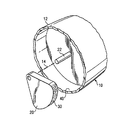
図1は、本発明によるコンピュータ入力ペン10の一実施形態を示す図である。コンピュータ入力ペン10は、限定はしないが、個人情報端末および他の型の手持ち式電子デバイス、ノートブックコンピュータ、タブレットパーソナルコンピュータ、および電子白板デバイスなどの種々の異なる型の電子装置に関連する入力操作を行うための任意のペン型デバイスである。図1に示す実施形態において、コンピュータ入力ペン10は一般に、長手方向軸14が中心に延びる円筒ハウジング12を備える。簡潔に言えば、本発明の実施形態は、コンピュータ入力ペン10の転がりを抑えるか、または、実質的に防止し、一方で、その円筒形状に基づいて、電子装置の収納エリアまたは区画内でのコンピュータ入力ペン10の都合のよい収納を可能にする。
FIG. 1 is a diagram illustrating one embodiment of a
図2A〜図2Dは、図1のライン2−2に沿って切り取ったコンピュータ入力ペン10の実施形態を示す断面図である。図2A〜図2Dを参照すると、コンピュータ入力ペン10は、コンピュータ入力ペン10の軸14に対して偏心して配設された錘20を備える。錘20は、錘20の重心が、コンピュータ入力ペン10の軸14から外れているような任意のタイプの幾何学的構成を備える。簡潔に言えば、錘20とペン10の対応する部分の間で所望のまたは所定のレベルの摩擦を有する錘20を、ペン10のハウジング12内に可動に配設して、錘20とペン10の対応する部分との間の運動から生ずるエネルギーを吸収するか、または、その他の方法で消散させることによって、ペン10の転がりを抑える、または、実質的に防止する。
2A-2D are cross-sectional views illustrating an embodiment of the
図2A〜図2Dに示す実施形態において、錘20は、軸14に略一致して配設された軸22に回転可能に連結される。しかしながら、錘20は、錘20のハウジング12に対する運動を可能にするように、他の方法でハウジング12内で連結されるか、または配設されてもよいことが理解されるべきである。図2Aおよび図2Bに示す実施形態において、軸22と錘20の間に所望の、または所定のレベルの摩擦を与えて、錘20の軸22に対する回転運動から生ずる錘20と軸22との間の回転エネルギーを吸収するか、または、消散させる。たとえば、図2Aに示す実施形態において、摩擦部材30が錘20の対応する面に面するか、またはその他の方法で係合する軸22の表面上に配設され、錘20と軸22との間の回転エネルギーが摩擦部材30によって吸収されるようにし、それによって、コンピュータ入力ペン10の転がりが抑えられるか、または実質的に防止される。摩擦部材30は、限定はしないが、ペン10の所望の部品のやすり状表面、またはギザギザの表面などの、ペン10の部品の一体に形成された摩擦面である。摩擦部材30はまた、限定はしないが、ペン10の所望の部品に粘着的に固定された摩擦材料などの、ペン10の所望の部品に接着されるか、またはその他の方法で固着された個別の部材を含む。
In the embodiment shown in FIGS. 2A to 2D, the
図2Bに示す実施形態では、摩擦部材が軸22の対応する面に面するか、または、その他の方法で係合する錘20の表面上に配設されて、錘20と軸22との間の回転エネルギーが吸収される。図2Aおよび図2Bに示す実施形態において、摩擦部材30は、軸22か、錘20のいずれかに配設される。しかしながら、摩擦部材30はまた、軸22と錘20の両方に配設されてもよいことが理解されるべきである。こうして、動作時、摩擦部材30は、錘20と軸22の対応する運動面間に所望のレベルの摩擦を与え、それによって、ペン10の任意の転がり運動から生ずる錘20と軸22との間の回転エネルギーが、摩擦部材30によって吸収される。
In the embodiment shown in FIG. 2B, the friction member faces the corresponding surface of the
図2Cに示す実施形態において、摩擦部材30は、ハウジング12の内面40に面するか、またはその他の方法で係合する錘20の表面に沿って配設される。たとえば、図2Cに示す実施形態において、錘20がハウジング12内でハウジング12の内面40に対して回転する時に、錘20のハウジング12に対する回転エネルギーが摩擦部材30によって吸収される。別法として、または、付加的に、摩擦部材30はまた、図2Dの実施形態に示すように、ハウジング12の内面40上に配設することができる。こうして、図2Cおよび図2Dに示す実施形態において、摩擦部材30が錘20の係合面および/またはハウジング12の内面40上に配設されて、ペン10の任意の転がり運動から生ずる、錘20とハウジング12の内面40との間の回転エネルギーを吸収する。先に述べたように、摩擦部材30は錘20および/またはハウジング12の内面40上に一体に形成することができる。摩擦部材30はまた、錘20の表面および/またはハウジング12の内面40に固着されるか、またはその他の方法で結合された個別の部材を含むことができる。さらに、摩擦部材30は、錘20の表面、軸22の表面、および/または、ハウジング12の内面40、あるいは、それらの任意の組み合わせ上に配設することが理解されるべきである。摩擦部材30は、錘20の他の表面、および/または、錘20に接触するかその他の方法で係合するペン10の他の表面上に配設されて、錘20のペン10の別の表面に対する運動から生ずるエネルギーを吸収するか、またはその他の方法で消散することができることも理解されるべきである。
In the embodiment shown in FIG. 2C, the
図3Aおよび図3Bに示す実施形態において、錘50は、錘50の重心が、軸14から外れるように、ハウジング12内で可動に配設される。図3Aに示す実施形態において、摩擦部材30はハウジング12の内面40に面するか、または、その他の方法で係合する錘50の表面上に配設されて、ペン10の任意の転がりから生ずる錘50とハウジング12の内面40との間の回転エネルギーを吸収する。付加的に、または、代替的に、摩擦部材30は、図3Bの実施形態で最もよく示されるように、ハウジング12の内面40上に配設することができる。図3Aおよび図3Bに示す実施形態において、ペン10の軸14に対して外れた重心を与え、一方で、ペン10の転がり運動から生ずるエネルギーの消散を錘50に対して可能にするような幾何学的形状を有する錘50が形成されるのが好ましい。たとえば、図3Aおよび図3Bに示す実施形態において、弧状に形成された周縁面60を有する錘50が形成されて、面60の任意の面とハウジング12の内面40との係合が可能になる。しかしながら、他の幾何学的構成の錘50を用いることができることが理解されるべきである。
In the embodiment shown in FIGS. 3A and 3B, the
こうして、動作時、コンピュータ入力ペン10が特定の作業面上でころがる場合、錘20、50とコンピュータ入力ペン10の対応する部分との間の回転エネルギーが、摩擦部材30によって吸収されるか、またはその他の方法で消散させられるように、所望のレベルの摩擦が錘20、50に対して与えられ、それによって、コンピュータ入力ペン10の連続した転がりが抑制されるか、または実質的に防止される。
Thus, in operation, when the
10 コンピュータ入力ペン
12 円筒ハウジング
14 長手方向軸
20 錘
22 軸
30 摩擦部材
10
Claims (8)
錘とを備え、前記錘は、前記円筒ハウジング内で、前記円筒ハウジングの長手方向軸に対して偏心して配設され、前記錘に対する前記円筒ハウジングの回転エネルギーを吸収するように、所望のレベルの摩擦で、前記円筒ハウジングに対して回転可能に連結することを特徴とするコンピュータ入力ペン。 A cylindrical housing;
A weight, wherein the weight is disposed eccentrically within the cylindrical housing with respect to the longitudinal axis of the cylindrical housing, and absorbs rotational energy of the cylindrical housing relative to the weight at a desired level. A computer input pen, wherein the pen is rotatably connected to the cylindrical housing by friction.
Applications Claiming Priority (1)
| Application Number | Priority Date | Filing Date | Title |
|---|---|---|---|
| US10/814,538 US7928966B2 (en) | 2004-03-31 | 2004-03-31 | Computer input pen apparatus |
Publications (2)
| Publication Number | Publication Date |
|---|---|
| JP2005293571A true JP2005293571A (en) | 2005-10-20 |
| JP3947541B2 JP3947541B2 (en) | 2007-07-25 |
Family
ID=35053741
Family Applications (1)
| Application Number | Title | Priority Date | Filing Date |
|---|---|---|---|
| JP2005072629A Expired - Fee Related JP3947541B2 (en) | 2004-03-31 | 2005-03-15 | Computer input pen device |
Country Status (2)
| Country | Link |
|---|---|
| US (1) | US7928966B2 (en) |
| JP (1) | JP3947541B2 (en) |
Cited By (1)
| Publication number | Priority date | Publication date | Assignee | Title |
|---|---|---|---|---|
| JP2012166504A (en) * | 2011-02-16 | 2012-09-06 | Tombow Pencil Co Ltd | Rolling prevention writing utensil |
Families Citing this family (7)
| Publication number | Priority date | Publication date | Assignee | Title |
|---|---|---|---|---|
| JP5235472B2 (en) * | 2008-04-01 | 2013-07-10 | 株式会社ワコム | Electronic pen |
| US20100013651A1 (en) * | 2008-07-15 | 2010-01-21 | Sony Ericsson Mobile Communications Ab | Device with display and controller for controlling displayed information in response to movement |
| CN201725288U (en) * | 2010-05-27 | 2011-01-26 | 深圳富泰宏精密工业有限公司 | Touch-sensitive pen |
| US9886088B2 (en) * | 2012-08-08 | 2018-02-06 | Microsoft Technology Licensing, Llc | Physically modulating friction in a stylus |
| KR102013940B1 (en) * | 2012-12-24 | 2019-10-21 | 삼성전자주식회사 | Method for managing security for applications and an electronic device thereof |
| US10338699B2 (en) | 2015-06-25 | 2019-07-02 | Microsoft Technology Licensing, Llc | Variable density device profile |
| JP2021122812A (en) * | 2020-02-10 | 2021-08-30 | パナソニックIpマネジメント株式会社 | Portable electrolytic water sprayer |
Family Cites Families (9)
| Publication number | Priority date | Publication date | Assignee | Title |
|---|---|---|---|---|
| US4127338A (en) * | 1976-10-27 | 1978-11-28 | Laybourne Sidney C | Writing instrument |
| EP0413607A3 (en) * | 1989-08-18 | 1991-04-03 | Matsushita Electric Industrial Co., Ltd. | Pen-type computer input device |
| SE469829B (en) * | 1992-02-03 | 1993-09-27 | Maarten Bergstroem | Pen |
| JPH0672087A (en) | 1992-06-10 | 1994-03-15 | Jitsupu:Kk | Portable motor-driven vibrator |
| EP0587162B1 (en) * | 1992-09-11 | 2002-02-06 | Canon Kabushiki Kaisha | Information processing apparatus |
| US5530208A (en) * | 1992-10-20 | 1996-06-25 | Samsung Electronics Co., Ltd. | Pen computer pen gripping mechanism |
| US5898427A (en) * | 1994-03-18 | 1999-04-27 | Sharp Kabushiki Kaisha | Pen, used for input to electronic apparatus, including a weighted member disposed in the pen to create a radially eccentric center of gravity within the pen |
| US6215480B1 (en) * | 1998-09-02 | 2001-04-10 | International Business Machines Corporation | Dynamic cylindrical display for pen-sized computing |
| US7199791B2 (en) * | 2003-10-23 | 2007-04-03 | Avago Technologies Ecbu Ip (Singapore) Pte. Ltd. | Pen mouse |
-
2004
- 2004-03-31 US US10/814,538 patent/US7928966B2/en not_active Expired - Fee Related
-
2005
- 2005-03-15 JP JP2005072629A patent/JP3947541B2/en not_active Expired - Fee Related
Cited By (1)
| Publication number | Priority date | Publication date | Assignee | Title |
|---|---|---|---|---|
| JP2012166504A (en) * | 2011-02-16 | 2012-09-06 | Tombow Pencil Co Ltd | Rolling prevention writing utensil |
Also Published As
| Publication number | Publication date |
|---|---|
| US20050219233A1 (en) | 2005-10-06 |
| JP3947541B2 (en) | 2007-07-25 |
| US7928966B2 (en) | 2011-04-19 |
Similar Documents
| Publication | Publication Date | Title |
|---|---|---|
| TWI261743B (en) | Dynamic absorber system and notebook computer utilizing the same | |
| US7379051B2 (en) | Foldable computer mouse | |
| JP3947541B2 (en) | Computer input pen device | |
| US20090237878A1 (en) | Electronic device structure | |
| JP2004251938A (en) | LCD display panel protection structure | |
| JP4980317B2 (en) | Information processing device | |
| WO2015129556A1 (en) | Gesture input device | |
| US6036287A (en) | Portable computer with endurance against shock | |
| KR101955932B1 (en) | Notebook with a removable pad-typed mouse | |
| KR102273503B1 (en) | Portable mobile terminal apparatus for shock prevention | |
| JP2012156244A (en) | Electronic equipment | |
| JP4767727B2 (en) | Mobile type input device with rotating structure | |
| CN106504646A (en) | Flexible display device | |
| JP5078804B2 (en) | Information processing device | |
| JP2003240012A (en) | Power transmission mechanism for in-vehicle electronic devices | |
| CN100395687C (en) | Height adjusting device | |
| KR100903293B1 (en) | Stylus pen | |
| US20100019108A1 (en) | Holding apparatus and pivot structure thereof | |
| US7375296B2 (en) | Keyboard | |
| CN223411819U (en) | monitor | |
| JPH07104907A (en) | Pen input electronic equipment | |
| JP2004360809A (en) | Gear with torque limiter and power transmitting mechanism of electronic apparatus | |
| JP2957872B2 (en) | Electronic equipment with trackball | |
| JP2957869B2 (en) | Electronic equipment with trackball | |
| US20150138706A1 (en) | Supporting structure for portable electronic device |
Legal Events
| Date | Code | Title | Description |
|---|---|---|---|
| A977 | Report on retrieval |
Free format text: JAPANESE INTERMEDIATE CODE: A971007 Effective date: 20061113 |
|
| A131 | Notification of reasons for refusal |
Free format text: JAPANESE INTERMEDIATE CODE: A131 Effective date: 20061205 |
|
| A521 | Request for written amendment filed |
Free format text: JAPANESE INTERMEDIATE CODE: A523 Effective date: 20070222 |
|
| TRDD | Decision of grant or rejection written | ||
| A01 | Written decision to grant a patent or to grant a registration (utility model) |
Free format text: JAPANESE INTERMEDIATE CODE: A01 Effective date: 20070320 |
|
| A61 | First payment of annual fees (during grant procedure) |
Free format text: JAPANESE INTERMEDIATE CODE: A61 Effective date: 20070413 |
|
| R150 | Certificate of patent or registration of utility model |
Free format text: JAPANESE INTERMEDIATE CODE: R150 |
|
| FPAY | Renewal fee payment (event date is renewal date of database) |
Free format text: PAYMENT UNTIL: 20100420 Year of fee payment: 3 |
|
| FPAY | Renewal fee payment (event date is renewal date of database) |
Free format text: PAYMENT UNTIL: 20110420 Year of fee payment: 4 |
|
| FPAY | Renewal fee payment (event date is renewal date of database) |
Free format text: PAYMENT UNTIL: 20120420 Year of fee payment: 5 |
|
| FPAY | Renewal fee payment (event date is renewal date of database) |
Free format text: PAYMENT UNTIL: 20120420 Year of fee payment: 5 |
|
| FPAY | Renewal fee payment (event date is renewal date of database) |
Free format text: PAYMENT UNTIL: 20130420 Year of fee payment: 6 |
|
| LAPS | Cancellation because of no payment of annual fees |