JP2005293479A - Object danger decision device - Google Patents
Object danger decision device Download PDFInfo
- Publication number
- JP2005293479A JP2005293479A JP2004111103A JP2004111103A JP2005293479A JP 2005293479 A JP2005293479 A JP 2005293479A JP 2004111103 A JP2004111103 A JP 2004111103A JP 2004111103 A JP2004111103 A JP 2004111103A JP 2005293479 A JP2005293479 A JP 2005293479A
- Authority
- JP
- Japan
- Prior art keywords
- risk determination
- danger
- range
- risk
- determination range
- Prior art date
- Legal status (The legal status is an assumption and is not a legal conclusion. Google has not performed a legal analysis and makes no representation as to the accuracy of the status listed.)
- Granted
Links
Images
Landscapes
- Traffic Control Systems (AREA)
- Fittings On The Vehicle Exterior For Carrying Loads, And Devices For Holding Or Mounting Articles (AREA)
Abstract
Description
本発明は、物体危険判定装置に関するものである。 The present invention relates to an object risk determination device.
従来、画像処理にて障害物を検出する障害物検知システムが提案されている(例えば、特許文献1参照。)。この特許文献1に開示されている障害物検知システムは、自動車に取り付けられたカメラからの画像を画像処理にて道路環境の種類、障害物の種類、相対位置等を算出し、緊急度合いが高い障害物について、その存在を画像表示等によって通知する。 Conventionally, an obstacle detection system that detects an obstacle by image processing has been proposed (see, for example, Patent Document 1). The obstacle detection system disclosed in Patent Document 1 calculates the type of road environment, the type of obstacle, the relative position, etc. by image processing of an image from a camera attached to an automobile, and has a high degree of urgency. The presence of an obstacle is notified by image display or the like.
また、物体の移動ベクトルに基づいて物体を識別する画像式歩行者検出装置が提案されている(例えば、特許文献2参照)。この特許文献2に開示されている画像式歩行者検出装置によれば、撮影した画像を2値化し、最新フレームの2値化画像と以前の2値化画像の差分をとることで撮影エリアを物体なし、物体あり、物体退却、物体進入に分け(4値化)、これら夫々に対応する画像の分布により物体の移動ベクトルを算定し、各移動ベクトルの方向と横断方向の比較に基づいて歩行者を識別する。
上述した、従来の障害物検知システム、及び画像式歩行者検出装置は、何れも画像全体に対して画像処理を施さなければならず、膨大な量の計算が必要となる。また、従来の画像式歩行者検出装置の検出結果を用いて歩行者に対する危険判定を行う場合、従来の画像式歩行者検出装置では、移動ベクトルの方向が横断歩道に平行(角度θ=0又は180度)であるものを歩行者として検出するため、その移動ベクトルの方向が横断歩道に平行となる歩行者以外の物体を検出する可能性がある。そのため、的確な危険判定を行うことができなくなる。 The above-described conventional obstacle detection system and image-type pedestrian detection device both have to perform image processing on the entire image, and require a huge amount of calculation. In addition, when the risk determination for the pedestrian is performed using the detection result of the conventional image type pedestrian detection device, the direction of the movement vector is parallel to the pedestrian crossing (angle θ = 0 or 180 degrees) is detected as a pedestrian, and there is a possibility of detecting an object other than a pedestrian whose movement vector is parallel to the pedestrian crossing. As a result, accurate risk determination cannot be performed.
本発明は、かかる問題を鑑みてなされたもので、物体に対する危険判定を的確に行うことができる物体危険判定装置を提供することを目的とする。 The present invention has been made in view of such a problem, and an object of the present invention is to provide an object risk determination device that can accurately determine the risk of an object.
請求項1に記載の物体危険判定装置は、視線方向、及び瞳孔の開き度合いを検出する検出手段と、視線方向の風景の画像を撮影する撮像手段と、視線方向に基づいて、画像における視点の位置を特定する視点特定手段と、視点特定手段の特定する視点の位置を基準として、画像上に危険判定の対象範囲とすべき危険判定範囲を設定する危険判定範囲設定手段と、瞳孔の開き度合いに基づいて、危険判定範囲内に写し出される物体を特定する物体特定手段と、撮像手段の撮影した前回までの画像と今回の画像とに基づいて、危険判定範囲内に写し出される物体の移動ベクトルを算出する移動ベクトル算出手段と、移動ベクトルに基づいて、物体特定手段によって特定される物体に応じた危険判定を行う危険判定手段を備えることを特徴とする。 The object risk determination apparatus according to claim 1 is a detection unit that detects a gaze direction and a degree of opening of a pupil, an imaging unit that captures an image of a landscape in the gaze direction, and a viewpoint of an image based on the gaze direction. A viewpoint identifying unit that identifies a position, a risk determination range setting unit that sets a risk determination range that should be a risk determination target range on the image, based on the position of the viewpoint that the viewpoint specifying unit specifies, and a degree of pupil opening Based on the object identification means for identifying the object to be projected within the risk determination range, and the movement vector of the object to be projected within the risk determination range based on the previous image and the current image captured by the imaging means. It is characterized by comprising a movement vector calculation means for calculating, and a risk determination means for making a risk determination according to the object specified by the object specifying means based on the movement vector.
このように、本発明の物体危険判定装置は、画像上における視点の位置を基準として危険判定の対象範囲とすべき危険判定範囲を設定し、瞳孔の開き度合いに基づいて危険判定範囲内に写し出される物体を特定する。そして、危険判定範囲内に写し出される物体の移動ベクトルに基づいて特定した物体に応じた危険判定を行う。 As described above, the object risk determination device according to the present invention sets the risk determination range to be the target range of the risk determination based on the position of the viewpoint on the image, and projects it within the risk determination range based on the degree of pupil opening. Identify the object Then, the risk determination according to the object specified based on the movement vector of the object projected in the risk determination range is performed.
これにより、移動ベクトルを算出する範囲は危険判定範囲内に限定されるため、画像全体に対して移動ベクトルを算出する場合に比べその計算量を低減することができる。また、瞳孔の開き度合いに基づいて物体を特定するため、その物体に応じた危険判定を的確に行うことが可能となる。 Thereby, since the range for calculating the movement vector is limited to the risk determination range, the amount of calculation can be reduced compared to the case of calculating the movement vector for the entire image. Further, since the object is specified based on the degree of opening of the pupil, it is possible to accurately perform the risk determination according to the object.
請求項2に記載の物体危険判定装置は、道路の分岐地点、合流地点、交差点、及び横断歩道の少なくとも何れかの1つの危険が潜在する危険地点の種類と位置とを含む道路データを記憶する道路データ記憶手段と、道路データ記憶手段の記憶する道路データから視線方向に存在する危険地点に関する情報を取得する危険地点情報取得手段とを備え、物体特定手段は、瞳孔の開き度合い、及び危険地点情報取得手段の取得する危険地点に関する情報の少なくとも一方に基づいて、危険判定範囲内に写し出される物体を特定することを特徴とする。 The object danger determination device according to claim 2 stores road data including a type and a position of a danger point in which at least one of a road branch point, a junction point, an intersection, and a pedestrian crossing has potential danger. Road data storage means, and danger point information acquisition means for acquiring information on danger points existing in the line-of-sight direction from the road data stored in the road data storage means. Based on at least one of the information on the danger point acquired by the information acquisition means, an object to be projected within the danger determination range is specified.
例えば、ナビゲーション装置等に用いられる地図データには、前述の危険地点に関する道路データが含まれている。従って、地図データに含まれる道路データから、道路の分岐地点、合流地点、交差点、及び横断歩道等の危険地点に関する情報を取得して、危険判定範囲内に写し出される物体を特定することができる。 For example, the map data used for a navigation device or the like includes road data relating to the above-mentioned danger points. Therefore, it is possible to acquire information on danger points such as road branch points, merge points, intersections, and pedestrian crossings from the road data included in the map data, and specify an object to be projected within the danger determination range.
請求項3に記載の物体危険判定装置は、物体特定手段は、物体情報取得手段の取得した物体に関する情報に基づく画像上の位置が危険判定範囲内に位置する場合、又は/及び瞳孔の開き度合いが通常の開き度合い以上である場合、危険判定範囲内に写し出される物体は危険が潜在する危険地点であると特定し、瞳孔の開き度合いが通常の開き度合いに満たない場合、危険判定範囲内に写し出される物体は移動物体であると特定することを特徴とする。 The object risk determination apparatus according to claim 3, wherein the object specifying unit is configured such that the position on the image based on the information on the object acquired by the object information acquisition unit is within the risk determination range, and / or the degree of opening of the pupil Is greater than the normal opening degree, the object projected in the danger judgment range is identified as a danger point where the danger is latent, and if the pupil opening degree is less than the normal opening degree, it is within the danger judgment range. The object to be projected is specified as a moving object.
自動車等の車両を運転する運転者は、進行方向の周囲に存在する物体を視認しながら運転操作を行うが、例えば、歩行者、軽車両、他車両等の移動中の物体については、その物体の詳細な点(例えば、移動方向等)まで認識して、自車両に対して危険であるか否かを判断する。一方、横断歩道や交差点等の自発的に移動しない物体については、自車両に対して危険でないため、その物体の詳細な点までは認識しない。また、人の目は、物体の詳細な点まで認識しようとする場合、目に入射する光の量を抑えようとする(目を凝らす)ため、瞳孔の開き度合いが通常よりも小さく(又は、通常の開き度合い以下と)なることが知られている。 A driver driving a vehicle such as an automobile performs a driving operation while visually recognizing an object existing around the traveling direction. For example, for a moving object such as a pedestrian, a light vehicle, or another vehicle, the object The detailed points (for example, the moving direction, etc.) are recognized to determine whether or not the vehicle is dangerous. On the other hand, an object that does not move spontaneously, such as a pedestrian crossing or an intersection, is not dangerous to the host vehicle, and therefore does not recognize the detailed points of the object. In addition, when the human eye tries to recognize a detailed point of an object, the degree of opening of the pupil is smaller than usual (or, in order to suppress the amount of light incident on the eye). It is known that the degree of opening is below the normal degree.
このことから、瞳孔の開き度合いが通常よりも小さい(又は、通常の開き度合い以下の)場合、運転者は、移動中の歩行者、軽車両、他車両等の移動物体に視線を向けていると考えられる。また、瞳孔の開き度合いが通常以上の(又は、通常の開き度合いを超える)場合、運転者は、横断歩道や交差点等の自発的に移動しないものの危険が潜在する危険地点(危険ポイント)に視線を向けていると考えられる。このように、瞳孔の開き度合いによって、危険判定範囲内に写し出される物体を特定することができる。 From this, when the degree of opening of the pupil is smaller than normal (or less than the normal degree of opening), the driver looks at a moving object such as a moving pedestrian, a light vehicle, or another vehicle. it is conceivable that. In addition, when the degree of pupil opening is greater than normal (or exceeds the normal degree of opening), the driver looks at dangerous points (danger points) that do not move spontaneously, such as pedestrian crossings and intersections. It is thought that In this way, the object to be projected within the danger determination range can be specified by the degree of pupil opening.
また、地図データに含まれる道路データから取得した危険ポイントが危険判定範囲内に位置する場合にも、危険判定範囲内に写し出される物体が危険ポイントであると特定することができる。 In addition, even when the danger point acquired from the road data included in the map data is located within the danger determination range, it is possible to specify that the object projected in the danger determination range is the danger point.
請求項4に記載の物体危険判定装置によれば、物体特定手段は、物体情報取得手段の取得した物体に関する情報に基づく画像上の位置が危険判定範囲内に位置する場合、又は/及び瞳孔の開き度合いが通常の開き度合いを超える場合、危険判定範囲内に写し出される物体は危険が潜在する危険地点であると特定し、瞳孔の開き度合いが通常の開き度合い以下の場合、危険判定範囲内に写し出される物体は移動物体であると特定することを特徴とする。 According to the object risk determination apparatus of the fourth aspect, the object specifying unit is configured such that the position on the image based on the information regarding the object acquired by the object information acquisition unit is within the risk determination range, and / or the pupil If the degree of opening exceeds the normal degree of opening, the object to be projected within the danger judgment range is identified as a danger point with potential danger, and if the degree of pupil opening is less than the normal degree of opening, it is within the danger judgment range. The object to be projected is specified as a moving object.
これにより、瞳孔の開き度合いによって、危険判定範囲内に写し出される物体を特定し、また、地図データに含まれる道路データから取得した危険ポイントが危険判定範囲内に位置する場合にも、危険判定範囲内に写し出される物体が危険ポイントであると特定することができる。 Thus, the risk judgment range can be determined even when the object to be projected in the risk judgment range is specified by the degree of opening of the pupil, and the danger point acquired from the road data included in the map data is located in the risk judgment range. It is possible to specify that the object projected inside is a danger point.
請求項5に記載の物体危険判定装置は、撮像手段によって撮影された画像内の動きに応じて、危険判定範囲設定手段の設定する危険判定範囲の設定位置を追従させる危険判定範囲追従手段を備え、移動ベクトル算出手段は、危険判定範囲追従手段によって追従された危険判定範囲内に写し出される物体の移動ベクトルを算出することを特徴とする。 According to a fifth aspect of the present invention, there is provided an object risk determination apparatus including a risk determination range tracking unit that follows a set position of a risk determination range set by the risk determination range setting unit in accordance with a movement in an image captured by the imaging unit. The movement vector calculation means calculates a movement vector of an object projected in the danger determination range followed by the danger determination range tracking means.
例えば、撮像手段が自動車等の移動体に搭載され、その進行方向の風景の画像を撮影するものである場合、その撮像手段によって撮影された画像内の物体は、移動体の進行方向と相反する方向へ移動する。従って、画像内の動きに危険判定範囲の設定位置を追従させることで、画像に写し出される物体から視線を外した場合であっても、その物体の位置を継続して追従することができる。 For example, when the imaging unit is mounted on a moving body such as an automobile and captures an image of a landscape in the traveling direction, the object in the image captured by the imaging unit conflicts with the traveling direction of the moving body. Move in the direction. Therefore, by causing the set position of the danger determination range to follow the movement in the image, even when the line of sight is removed from the object shown in the image, the position of the object can be continuously followed.
請求項6に記載の物体危険判定装置によれば、危険判定範囲追従手段は、危険判定範囲の設定位置を追従することで危険判定範囲が画像から外れる場合、危険判定範囲を追従対象から除外することを特徴とする。これにより、危険でない危険判定範囲内に写し出される物体を判定対象から除外することができる。 According to the object risk determination apparatus of the sixth aspect, the risk determination range follower excludes the risk determination range from the tracking target when the risk determination range deviates from the image by following the set position of the risk determination range. It is characterized by that. As a result, it is possible to exclude an object that is projected within the danger determination range that is not dangerous from the determination target.
請求項7に記載の物体危険判定装置によれば、移動ベクトル算出手段は、危険判定範囲内の移動ベクトルの平均的な移動方向を示す平均移動ベクトルをさらに算出し、危険判定手段は、移動ベクトルの方向成分から平均移動ベクトルの方向成分を除いた実移動ベクトルに基づいて危険判定を行うことを特徴とする。 According to the object risk determination apparatus of the seventh aspect, the movement vector calculation means further calculates an average movement vector indicating an average movement direction of the movement vectors within the danger determination range, and the danger determination means includes the movement vector. The risk determination is performed based on an actual movement vector obtained by subtracting the direction component of the average movement vector from the direction component.
これにより、例えば、歩行者等の移動速度の低い物体であっても、その物体の実際の動きに応じた移動ベクトルに基づいて危険判定を行うため、誤った判定を抑制することができる。 Thereby, even if it is an object with low moving speeds, such as a pedestrian, for example, since risk determination is performed based on the movement vector according to the actual motion of the object, an erroneous determination can be suppressed.
請求項8に記載の物体危険判定装置によれば、危険判定範囲設定手段は、危険判定範囲を設定する際、危険判定範囲の境界を取り囲む境界エリアを設定し、移動ベクトル算出手段は、境界の内側、及び境界エリア内の少なくとも一方の移動ベクトルの平均的な移動方向を示す平均移動ベクトルを算出することを特徴とする。これにより、平均移動ベクトルを算出する範囲が狭まるため、平均移動ベクトルを算出する際の計算量を低減することができる。 According to the object risk determination apparatus of the eighth aspect, when the risk determination range is set, the risk determination range setting unit sets a boundary area surrounding the boundary of the risk determination range, and the movement vector calculation unit is An average movement vector indicating an average movement direction of at least one of the movement vectors inside and in the boundary area is calculated. Thereby, since the range which calculates an average movement vector becomes narrow, the calculation amount at the time of calculating an average movement vector can be reduced.
請求項9に記載の物体危険判定装置によれば、撮像手段は、移動体に搭載され、移動体の進行方向の風景の画像を撮影するものであって、危険判定手段は、危険地点に対して、危険判定範囲に進入した移動ベクトルが存在するか否かを判定し、移動物体に対して、危険判定範囲から移動体へ向かう移動ベクトルが存在するか否かを判定することを特徴とする。 According to the object danger determination apparatus of the ninth aspect, the imaging means is mounted on the moving body and captures an image of a landscape in the traveling direction of the moving body, and the danger determination means And determining whether or not there is a movement vector that has entered the danger determination range, and determining whether or not there is a movement vector from the danger determination range toward the moving object for the moving object. .
これにより、横断歩道や交差点等の危険ポイントに進入した歩行者や軽車両等の進入物体の存在有無を判定することができる。また、移動体へ向かってくる歩行者、軽車両、他車両等の移動物体の存在有無を判定することができる。 Accordingly, it is possible to determine the presence or absence of an entering object such as a pedestrian or a light vehicle that has entered a danger point such as a pedestrian crossing or an intersection. In addition, it is possible to determine the presence or absence of moving objects such as pedestrians, light vehicles, and other vehicles that are heading toward the moving body.
請求項10に記載の物体危険判定装置によれば、平均移動ベクトルの示す画像における角度で危険判定範囲を複数に分割する危険判定範囲分割手段を備え、危険判定手段は、複数に分割された危険判定範囲毎の異なる判定条件に基づいて、危険判定を行うことを特徴とする。これにより、1つの危険判定範囲であっても、異なる判定条件に基づく危険判定を行うことができる。
According to the object risk determination apparatus according to
請求項11に記載の物体危険判定装置は、危険判定範囲分割手段は、移動ベクトルの数が略等しくなるように危険判定範囲を二つの範囲に分割するものであって、危険判定手段は、危険地点に対して、二分割された危険判定範囲のうち、移動体からの距離が短い側に存在する一方の危険判定範囲においては、移動体へ向かう移動ベクトルが存在するか否かを判定条件とし、移動体へ向かう移動ベクトルが存在する場合に危険な進入物体が存在すると判定し、二分割された危険判定範囲のうち、他方の危険判定範囲においては、一方の危険判定範囲へ向かう移動ベクトルが存在するか否かを判定条件とし、一方の危険判定範囲へ向かう移動ベクトルが存在する場合に危険な進入物体が存在すると判定し、移動物体に対して、二分割された危険判定範囲のうち、移動体からの距離が短い側に存在する一方の危険判定範囲においては、移動体へ向かう移動ベクトルが存在するか否かを判定条件とし、移動体へ向かう移動ベクトルが存在する場合に危険な移動物体が存在すると判定し、二分割された危険判定範囲のうち、他方の危険判定範囲においては、移動体から離れる方向へ向かう移動ベクトルが存在するか否かを判定条件とし、移動体から離れる方向へ向かう移動ベクトルが存在する場合に他方の危険判定範囲を危険判定の対象範囲から除外すると判定することを特徴とする。 The object risk determination device according to claim 11, wherein the risk determination range dividing means divides the risk determination range into two ranges so that the number of movement vectors is substantially equal, and the risk determination means In one of the danger determination ranges that are located on the shorter distance side from the moving object, the determination condition is whether or not there is a movement vector toward the moving object. When the movement vector toward the moving body exists, it is determined that there is a dangerous approaching object, and in the other risk determination range, the movement vector toward one risk determination range is It is determined whether there is a dangerous approaching object when there is a moving vector toward one of the risk determination ranges. In one danger judgment range that exists on the shorter distance side from the moving body in the range, the judgment condition is whether or not there is a moving vector toward the moving body, and there is a moving vector toward the moving body. It is determined that there is a dangerous moving object in the area, and in the other risk determination range of the two divided risk determination ranges, whether or not there is a movement vector that goes in a direction away from the moving object is used as a determination condition. When there is a movement vector that moves away from the body, the other risk determination range is determined to be excluded from the risk determination target range.
このように、危険ポイントに対して、移動体からの距離の短い側(一般に、画面中央に対して内側)の危険判定範囲においては、移動体へ向かう移動ベクトルの存在有無を判定条件としているため、例えば、横断歩道や交差点から飛び出してくる歩行者や軽車両等の危険な進入物体の存在有無を判定することができる。また、移動体からの距離の長い側(一般に、画面中央に対して外側)の危険判定範囲においては、前述した一方の危険判定範囲へ向かう移動ベクトルの存在有無を判定条件としているため、危険ポイントに進入した進入物体の存在有無を判定することができる。 As described above, in the danger determination range on the short distance side from the moving body (generally, the inner side with respect to the center of the screen) with respect to the dangerous point, the determination condition is the presence / absence of a moving vector toward the moving body. For example, it is possible to determine the presence or absence of a dangerous approaching object such as a pedestrian or light vehicle jumping out from a pedestrian crossing or an intersection. In addition, in the danger determination range on the longer distance side from the moving body (generally, the outer side with respect to the center of the screen), the presence or absence of the movement vector toward one of the risk determination ranges is used as the determination condition. The presence / absence of an approaching object that has entered can be determined.
また、移動物体に対して、移動体からの距離の短い側の危険判定範囲においては、移動体へ向かう移動ベクトルの存在有無を判定条件としているため、歩行者、軽車両、他車両等の危険な移動物体の存在有無を判定することができる。また、移動体からの距離の長い側の危険判定範囲においては、移動体から離れる方向へ向かう移動ベクトルの存在有無を判定条件し、移動体から離れる方向へ向かう移動ベクトルが存在する場合に、その他方の危険判定範囲を危険判定の対象範囲から除外する判定するため、危険な移動物体が存在しない危険判定範囲を判定しないようにすることができる。 In addition, in the danger determination range on the short distance side from the moving object with respect to the moving object, the presence / absence of a moving vector toward the moving object is used as the determination condition, so that the danger of pedestrians, light vehicles, other vehicles, etc. Presence or absence of a moving object can be determined. In addition, in the danger determination range on the longer distance side from the moving body, it is determined whether or not there is a moving vector going away from the moving body, and if there is a moving vector going away from the moving body, Since it is determined to exclude the risk determination range of the other from the target range of the risk determination, it is possible not to determine the risk determination range where there is no dangerous moving object.
請求項12に記載の物体危険判定装置によれば、危険判定手段は、危険地点に対して、危険判定範囲の境界の内側へ向かう移動ベクトルの始点、又は/及び終点が境界エリア内に位置するときに、危険判定範囲へ進入した危険な進入物体が存在すると判定し、移動物体に対して、移動ベクトルの始点、又は/及び終点が境界エリア内に位置するときに、危険判定範囲から移動体へ向かう危険な移動物体が存在すると判定することを特徴とする。 According to the object risk determination apparatus of the twelfth aspect, the risk determination means has the start point or / and the end point of the movement vector toward the inside of the boundary of the risk determination range with respect to the risk point in the boundary area. Sometimes it is determined that there is a dangerous approaching object that has entered the risk determination range, and the moving object moves from the risk determination range when the start point or / and end point of the movement vector is located within the boundary area with respect to the moving object. It is determined that there is a dangerous moving object toward
これにより、移動ベクトルが境界エリアを跨いだタイミングで危険な進入物体や移動物体が存在すると判定されるため、例えば、この危険判定の判定結果に応じて警報を発生する場合、煩わしい警報を発生しないようにすることができる。 As a result, since it is determined that there is a dangerous approaching object or moving object at the timing when the movement vector crosses the boundary area, for example, when an alarm is generated according to the determination result of the risk determination, a troublesome alarm is not generated. Can be.
請求項13に記載の物体危険判定装置は、危険判定手段によって危険な進入物体、又は/及び移動物体が存在すると判定された場合に警報を発生する警報発生手段を備えることを特徴とする。これにより、危険な物体の存在を知らせることができる。 According to a thirteenth aspect of the present invention, there is provided an object danger determination device comprising alarm generation means for generating an alarm when it is determined by the risk determination means that a dangerous approaching object and / or moving object is present. Thereby, the presence of a dangerous object can be notified.
請求項14に記載の物体危険判定装置によれば、危険判定範囲分割手段は、危険判定範囲毎に、移動体からの距離が短くなるに従って高い危険レベルを設定する危険レベル設定手段を備え、警報手段は、危険レベルの高低に応じた警報を発生することを特徴とする。 According to the object risk determination apparatus according to claim 14, the risk determination range dividing unit includes a risk level setting unit that sets a higher risk level as the distance from the moving body becomes shorter for each risk determination range, The means generates an alarm according to the level of the danger level.
すなわち、移動体からの距離が短い危険判定範囲に写し出される物体ほど、移動体に対して近い位置に存在するため、その物体の危険度は高い。従って、危険判定範囲毎に、移動体からの距離が短くなるに従って高い危険レベルを設定し、この危険レベルの高低に応じた警報を発生することで、危険度に応じた警報を発生することができる。 In other words, an object that is projected in the danger determination range with a short distance from the moving body is located closer to the moving body, and thus the risk level of the object is higher. Therefore, for each danger judgment range, a higher danger level is set as the distance from the moving body becomes shorter, and an alarm according to the level of the danger level can be generated to generate an alarm according to the danger level. it can.
以下、本発明の物体危険判定装置に関して、図面に基づいて説明する。なお、本実施形態では、自動車等の車両の進行方向の物体に対する危険判定を行う物体危険判定装置について説明する。 Hereinafter, the object danger determination device of the present invention will be described with reference to the drawings. In the present embodiment, an object risk determination apparatus that performs a risk determination on an object in the traveling direction of a vehicle such as an automobile will be described.
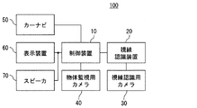
図1に、本実施形態における物体危険判定装置100の全体構成を示す。同図に示すように、物体危険判定装置100は、制御装置10、視線認識装置20、視線認識用カメラ30、物体監視用カメラ40、カーナビゲーション装置(以下、カーナビ)50、表示装置60、及びスピーカ70によって構成される。
FIG. 1 shows an overall configuration of an object
制御装置10は、マイクロコンピュータとして構成されるもので、何れも周知のCPU、ROM、RAM、I/O、及び、これら構成を接続するバスラインによって構成される。CPUは、ROMに記憶されるプログラムに従って所定の演算処理を実行する。
The
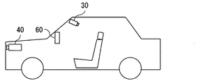
視線認識用カメラ30は、図2に示すように、自車両の乗員(例えば、運転者)の目の画像を撮影することができる車室内に配置され、撮影された目の画像を視線認識装置20へ出力する。また、視線認識用カメラ30は、制御装置10からの指示信号に応じて、フォーカス、シャッタースピード、フレームレート、出力ゲイン等の調整を行う。
As shown in FIG. 2, the line-of-
視線認識装置20は、視線認識用カメラ30によって撮影された目の画像に基づいて、乗員の視線方向と瞳孔の開き度合いを認識する。なお、視線方向は、自車両の特定位置(例えば、重心位置)を中心とし、自車両の前後(X軸)、左右(Y軸)、高さ(Z軸)の各座標軸によって構成される車両座標系に対する目の位置(アイポイント)[ΔX、ΔY、ΔZ]、及び、上記目の位置における視線方向の各座標軸に対する角度[αx、βy、γz]によって示される。
The line-of-
この目の画像から視線方向を認識する方法としては、例えば、特開平8−238222号公報に開示されている視線認識装置のように、角膜曲率中心と瞳孔中心の位置情報から視線方向を認識する方法をとればよい。 As a method for recognizing the line-of-sight direction from the eye image, for example, as in the line-of-sight recognition device disclosed in Japanese Patent Laid-Open No. 8-238222, the line-of-sight direction is recognized from position information of the corneal curvature center and the pupil center. Take the method.
また、瞳孔の開き度合いについては、撮影画像から瞳孔と虹彩(アイリス)との境界付近の画素値の変化を検出して(エッジ検出)、この検出したエッジからなる領域の大きさ(すなわち、瞳孔の大きさ)から瞳孔の開き度合いを認識すればよい。この視線認識装置20によって認識された乗員の視線方向と瞳孔の開き度合いの情報は、制御装置10へ出力される。
As for the degree of opening of the pupil, a change in pixel value in the vicinity of the boundary between the pupil and the iris (iris) is detected from the photographed image (edge detection), and the size of the area including the detected edge (that is, the pupil) The degree of opening of the pupil may be recognized from the size). Information on the sight line direction of the occupant and the degree of opening of the pupil recognized by the sight
物体監視用カメラ40は、図2に示すように、自車両の前部に配置され、自車両の進行方向の風景の画像を撮影する。物体監視用カメラ40は、視線認識用カメラ30と同様に、制御装置10からの指示信号に応じて、フォーカス、シャッタースピード、フレームレート、出力ゲイン等の調整を行い、撮影画像を制御装置10へ出力する。
As shown in FIG. 2, the
カーナビ50は、周知のごとく、車両の現在位置周辺の地図を表示する地図表示機能、所望の施設を検索する施設検索機能、目的地までの経路を誘導する経路誘導機能等の各種機能を実行するものである。このカーナビ50は、何れも図示しない位置検出器、地図データ入力器、制御回路によって構成される。
As is well known, the
位置検出器は、車両の現在位置を検出するもので、いずれも周知の地磁気センサ、及び衛星からの電波に基づいて車両の位置を検出するGPS(Global Positioning System)のためのGPS受信機等によって構成される。 The position detector detects the current position of the vehicle, both of which are known by a known geomagnetic sensor and a GPS receiver for GPS (Global Positioning System) that detects the position of the vehicle based on radio waves from a satellite. Composed.
地図データ入力器は、道路データ、背景データ、目印データ等から構成される地図データを入力するための装置であり、制御回路からの要請により各種データを送信する。これら各種データを記憶する記憶媒体としては、CD、DVD、HD(ハードディスク)等の大容量の記憶媒体が主に用いられる。 The map data input device is a device for inputting map data composed of road data, background data, landmark data, and the like, and transmits various data in response to requests from the control circuit. A large-capacity storage medium such as a CD, DVD, or HD (hard disk) is mainly used as a storage medium for storing these various data.
ここで、地図データを構成する道路データのリンクデータ及びノードデータについて説明する。先ず、リンクとは、地図上の各道路を交差・分岐・合流する点等の複数のノードにて分割し、それぞれのノード間をリンクとして規定されるものであり、リンクを接続することにより道路が構成される。リンクデータは、リンクを特定する固有番号(リンクID)、リンクの長さを示すリンク長、リンクの始端と終端の座標、道路名称、道路種別、道路幅員等の各データから構成されている。 Here, the link data and node data of the road data constituting the map data will be described. First, a link is defined by dividing each road on the map at a plurality of nodes such as intersections, branches, and merging points, and each node is defined as a link. Is configured. The link data is composed of data such as a unique number (link ID) that identifies the link, a link length that indicates the length of the link, coordinates of the start and end of the link, road name, road type, and road width.
一方、ノードデータは、地図上の各道路が分岐、合流、交差するノード毎に固有の番号を付したノードID、ノード座標、ノード名称、ノードに接続する全てのリンクのリンクIDが記述される接続リンクID、分岐地点、合流地点、交差点、及び横断歩道の何れかの地点に該当するかを示す地点の種類等の各データから構成されている。 On the other hand, the node data describes a node ID, a node coordinate, a node name, and a link ID of all the links connected to the node for each node where each road on the map branches, merges, and intersects. It consists of each data such as the type of a point indicating whether it corresponds to a connection link ID, a branch point, a merge point, an intersection, or a crosswalk.
このカーナビ50は、車両の現在位置を検出するとともに、車両の現在位置から所定距離以内の進行方向に存在する分岐地点、合流地点、交差点、及び横断歩道の少なくとも何れか1つの危険が潜在する危険地点の種類とその位置を示す地点情報を地図データから抽出する。そして、制御装置10からの要請がある場合に、その地点情報を制御装置10へ出力する。
The
これにより、制御装置10において、地図データに含まれる道路データから、道路の分岐地点、合流地点、交差点、及び横断歩道等の危険地点に関する情報を取得することができる。
Thereby, in the
表示装置60は、図2に示すように、乗員が見ることのできる位置に配置される。この表示装置60は、例えば液晶ディスプレイによって構成され、表示装置9の画面には、カーナビ50の各種機能に応じた画像を表示することができるとともに、乗員に対して注意喚起を行うための警告が表示される。スピーカ70は、乗員に対して注意喚起を行うための警報を出力したりする。
As shown in FIG. 2, the
制御装置10は、視線認識装置20によって認識された乗員の視線方向と瞳孔の開き度合いの情報と、物体監視用カメラ40によって撮影された画像を取得し、この取得した情報と画像に基づいて、自車両の進行方向に危険な物体が存在するか否かを判定し、その判定によって危険な物体が存在すると判定される場合に警報を発生する物体危険判定処理を実行する。
The
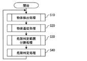
以下、本実施形態の特徴部分に係わる物体危険判定処理について、図5〜図15に示すフローチャートを用いて説明する。先ず、図5に示すステップ(以下、Sと記す)10では、物体検出処理を実行し、S20にて、その検出した物体に対して設定される危険判定範囲を画像の動きに追従させる物体追従処理を実行する。S30では、危険判定範囲を二分割する危険判定範囲分割処理を実行し、S40では、二分割された危険判定範囲における危険判定処理を実行する。 Hereinafter, the object risk determination process related to the characteristic part of the present embodiment will be described with reference to the flowcharts shown in FIGS. First, in step (hereinafter referred to as S) 10 shown in FIG. 5, object detection processing is executed, and in S20, object tracking for causing the risk determination range set for the detected object to follow the movement of the image. Execute the process. In S30, a risk determination range dividing process for dividing the risk determination range into two is executed. In S40, a risk determination process in the divided risk determination range is executed.
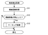
先ず、物体検出処理について、図6〜図8に示すフローチャートを用いて説明する。図6に示すS11では、視線認識処理を実行する。この視線認識処理では、視線認識装置20によって認識された乗員の視線方向の情報に基づいて、物体監視用カメラ40によって撮影された画像における乗員の視点位置を認識する。
First, the object detection process will be described with reference to the flowcharts shown in FIGS. In S11 shown in FIG. 6, a line-of-sight recognition process is executed. In this line-of-sight recognition process, the viewpoint position of the occupant in the image captured by the
この画像における視点位置は、車両座標系に対する目の位置(アイポイント)[ΔX、ΔY、ΔZ]、及び、上記目の位置における視線方向の各座標軸に対する角度[αx、βy、γz]と、物体監視用カメラ40の車両座標系に対する取り付け位置、撮影方向、及び撮影範囲に基づいて幾何学的に算出することで求めることができる。
The viewpoint position in this image includes the eye position (eye point) [ΔX, ΔY, ΔZ] with respect to the vehicle coordinate system, the angle [αx, βy, γz] with respect to each coordinate axis in the line-of-sight direction at the eye position, and the object It can be obtained by geometrically calculating based on the mounting position of the
S12では、視線移動が停止したか否かを判定する。ここで、肯定判定される場合にはS13のマーキング処理に移行し、否定判定される場合には、本物体検出処理を終了し、S20の物体追従処理を実行する。 In S12, it is determined whether the line-of-sight movement has stopped. Here, if an affirmative determination is made, the process proceeds to the marking process of S13. If a negative determination is made, the object detection process is terminated, and the object tracking process of S20 is executed.
このS12の判定は、具体的に言えば、画像における視点位置が所定時間以上同じ位置であるか否かを判定する。すなわち、一般に、人は、視覚によって物体が何であるのかを認識するために、ある程度の時間継続してその物体へ視線を向ける。従って、視点位置が所定時間(例えば、数百ミリ秒程度)以上同じ位置である場合に、運転者が視認した物体が把握できる。 More specifically, the determination in S12 determines whether or not the viewpoint position in the image is the same position for a predetermined time or more. That is, in general, in order to recognize what an object is visually, a person continuously looks at the object for a certain period of time. Therefore, when the viewpoint position is the same position for a predetermined time (for example, about several hundred milliseconds), the object viewed by the driver can be grasped.
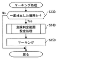
続いて、S13におけるマーキング処理について、図7に示すフローチャートを用いて説明する。図7に示すS130では、視点位置が以前に検出した画像上の場所であるか否かを判定する。言い換えれば、視点位置が既に存在する危険判定範囲以外の画像上の場所であるか否かを判定する。ここで、肯定判定される場合には、S140へ処理を進め、否定判定される場合にはS20の物体追従処理に移行する。 Then, the marking process in S13 is demonstrated using the flowchart shown in FIG. In S130 shown in FIG. 7, it is determined whether or not the viewpoint position is a place on the image detected previously. In other words, it is determined whether or not the viewpoint position is a place on the image outside the existing risk determination range. If the determination is affirmative, the process proceeds to S140. If the determination is negative, the process proceeds to the object tracking process of S20.
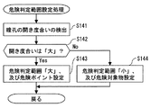
S140における危険判定範囲設定処理について、図8に示すフローチャートを用いて説明する。図8に示すS141では、視線認識装置20において乗員の瞳孔の開き度合いが検出され、S142では、この瞳孔の開き度合いが乗員の通常の瞳孔の開き度合い以上であるか否かを判定する。ここで、肯定判定される場合にはS143に処理を進め、否定判定される場合にはS144へ処理を進める。
The risk determination range setting process in S140 will be described using the flowchart shown in FIG. In S141 shown in FIG. 8, the degree of opening of the occupant's pupil is detected in the line-of-
S143では、乗員の視認した物体は、横断歩道や交差点等の自発的に移動しないものの危険が潜在する危険地点(以下、危険ポイント)であるとし、また、視点位置を基準とする危険判定範囲(大きさ「大」)を画像上に設定する。S144では、乗員の視認した物体は移動物体(以下、危険対象物)であるとし、また、視点位置を基準とする危険判定範囲(大きさ「小」)を画像上に設定する。このS143、及びS144の処理では、例えば、視点位置を中心とする円形の危険判定範囲を設定し、さらに、その危険判定範囲の境界を取り囲む境界エリア(A)を設定する。 In S143, the object visually recognized by the occupant is a dangerous point (hereinafter referred to as a dangerous point) that does not move spontaneously, such as a pedestrian crossing or an intersection, but also has a risk determination range (reference point) based on the viewpoint position ( Set “Large” on the image. In S144, the object visually recognized by the occupant is assumed to be a moving object (hereinafter referred to as a dangerous object), and a risk determination range (size “small”) based on the viewpoint position is set on the image. In the processes of S143 and S144, for example, a circular danger determination range centered on the viewpoint position is set, and a boundary area (A) surrounding the boundary of the risk determination range is set.
この図8に示す危険判定範囲設定処理は、瞳孔の開き度合いに基づいて危険判定範囲に写し出される物体を特定し、さらに、その開き度合いに応じた大きさの危険判定範囲を設定するものである。すなわち、自車両の運転者は、進行方向の周囲に存在する物体を視認しながら運転操作を行うが、例えば、歩行者、軽車両、他車両等の移動中の物体については、その物体の詳細な点(例えば、移動方向等)まで認識して、自車両に対して危険であるか否かを判断する。一方、横断歩道や交差点等の自発的に移動しない物体については、自車両に対して危険でないため、その物体の詳細な点までは認識しない。また、人の目は、物体の詳細な点まで認識しようとする場合、目に入射する光の量を抑えようとする(目を凝らす)ため、瞳孔の開き度合いが通常よりも小さく(又は、通常の開き度合い以下と)なることが知られている。 The risk determination range setting process shown in FIG. 8 specifies an object to be projected in the risk determination range based on the degree of pupil opening, and further sets a risk determination range having a size corresponding to the degree of opening. . That is, the driver of the host vehicle performs a driving operation while visually recognizing an object existing around the traveling direction. For example, for a moving object such as a pedestrian, a light vehicle, and another vehicle, details of the object Up to a certain point (for example, the moving direction), it is determined whether the vehicle is dangerous. On the other hand, an object that does not move spontaneously, such as a pedestrian crossing or an intersection, is not dangerous to the host vehicle, and therefore does not recognize the detailed points of the object. In addition, when the human eye tries to recognize a detailed point of an object, the degree of opening of the pupil is smaller than usual (or, in order to suppress the amount of light incident on the eye). It is known that the degree of opening is below the normal degree.
このことから、瞳孔の開き度合いが通常よりも小さい(又は、通常の開き度合い以下の)場合、運転者は、移動中の歩行者、軽車両、他車両等の移動物体である危険対象物に視線を向けていると考えられる。また、瞳孔の開き度合いが通常以上の(又は、通常の開き度合いを超える)場合、運転者は、横断歩道や交差点等の自発的に移動しないものの危険が潜在する危険地点(危険ポイント)に視線を向けていると考えられる。 From this, when the degree of opening of the pupil is smaller than normal (or less than the normal degree of opening), the driver can move to dangerous objects that are moving objects such as moving pedestrians, light vehicles, and other vehicles. It is thought that the gaze is turned. In addition, when the degree of pupil opening is greater than normal (or exceeds the normal degree of opening), the driver looks at dangerous points (danger points) that do not move spontaneously, such as pedestrian crossings and intersections. It is thought that
従って、瞳孔の開き度合いが通常よりも小さい(又は、通常の開き度合い以下の)場合、乗員の視認した(危険判定範囲内に写し出される)物体は危険対象物であると特定し、瞳孔の開き度合いが通常以上の(又は、通常の開き度合いを超える)場合、乗員の視認した物体は危険ポイントであると特定することができる。 Therefore, when the degree of opening of the pupil is smaller than normal (or less than the normal degree of opening), the object visually recognized by the occupant (photographed within the danger judgment range) is identified as a dangerous object, and the pupil is opened. If the degree is higher than normal (or exceeds the normal degree of opening), the object visually recognized by the occupant can be identified as a danger point.
なお、危険ポイントは、横断歩道や交差点等であり、その大きさが大きいため、危険ポイントに対して設定される危険判定範囲の大きさを大きく設定する。一方、危険対象物は、危険ポイントに比べて大きさが小さいため、危険対象物に対して設定される危険判定範囲の大きさを小さく設定する。さらに、画像における視点位置から距離を求め、この距離に応じて危険判定範囲の大きさを変更するようにしてもよい。 The risk points are pedestrian crossings, intersections, and the like, and are large in size, so the size of the risk determination range set for the risk point is set large. On the other hand, since the dangerous object is smaller in size than the dangerous point, the size of the danger determination range set for the dangerous object is set to be small. Furthermore, the distance may be obtained from the viewpoint position in the image, and the size of the danger determination range may be changed according to this distance.
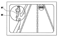
図7に示すS150では、乗員の視点位置(MP)を基準とする危険判定範囲(MK)をマーキングする。これにより、例えば、図3に示すように、乗員の視点位置(MP)の被写体であるカードレールとそのカードレールの隙間に存在する歩行者を含む危険判定範囲(MK)がマーキングされる。 In S150 shown in FIG. 7, the danger determination range (MK) is marked based on the viewpoint position (MP) of the passenger. Thereby, for example, as shown in FIG. 3, the risk determination range (MK) including the card rail that is the subject at the viewpoint position (MP) of the occupant and the pedestrian existing in the gap between the card rail is marked.
次に、S20における物体追従処理について、図9に示すフローチャートを用いて説明する。図9に示すS21では、危険判定範囲の位置を画像の動きに応じた方向へ移動させる。例えば、本実施形態のように、物体危険判定装置100が車両に搭載される場合、危険判定範囲は、車両の移動に伴って、車両の移動方向と相反する方向(略画面の下方)へ移動する。
Next, the object tracking process in S20 will be described using the flowchart shown in FIG. In S21 shown in FIG. 9, the position of the danger determination range is moved in a direction according to the movement of the image. For example, when the object
従って、画像の動きに危険判定範囲の位置を追従するように移動させることで、乗員が画像に写し出される物体から視線を外した場合であっても、その物体の位置を継続して追従することができる。 Therefore, by moving the image so that the position of the danger determination range follows the movement of the image, the occupant can continuously follow the position of the object even when the line of sight is removed from the object displayed in the image. Can do.
S22では、S21において移動した危険判定範囲が画面の外に位置するか否かを判定する。ここで、肯定判定される場合には、S23において、その危険判定範囲を追従対象から除外(削除)する。これにより、危険でなくなった危険判定範囲内に写し出される物体を危険判定の対象から除外することができる。 In S22, it is determined whether or not the danger determination range moved in S21 is located outside the screen. If the determination is affirmative, the risk determination range is excluded (deleted) from the tracking target in S23. As a result, it is possible to exclude an object that is projected within the danger determination range that is no longer dangerous from the risk determination target.
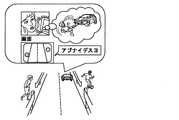
なお、図4に示すように、危険判定範囲を示すマーカを物体監視用カメラ40の撮影する画像に重ねて表示装置60に表示するようにしてもよい。これにより、車両の乗員は、表示装置60に表示される画像から危険判定範囲を確認ことができる。
In addition, as shown in FIG. 4, you may make it display the marker which shows a danger determination range on the
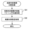
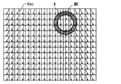
次に、危険判定範囲分割処理について、図10に示すフローチャートを用いて説明する。同図のS31では、図16に示すように、物体追従処理にて移動した危険判定範囲(MK)内の移動ベクトル(Vec)を算出する。 Next, the danger determination range dividing process will be described with reference to the flowchart shown in FIG. In S31 of the figure, as shown in FIG. 16, a movement vector (Vec) within the danger determination range (MK) moved by the object following process is calculated.
この移動ベクトル(Vec)を算出する場合には、例えば、物体監視用カメラ40の撮影する画像をフレーム単位で記憶しておき、前回のフレームと今回のフレームとを比較して、危険判定範囲内に含まれる画素の移動方向を示す移動ベクトルを算出する。このように、移動ベクトルを算出する範囲を危険判定範囲内に限定することで、画像全体に対して移動ベクトルを算出する場合に比べその計算量を低減することができる。
When calculating the movement vector (Vec), for example, an image captured by the
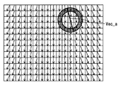
また、S31では、算出した移動ベクトルの平均的な移動方向を示す平均移動ベクトル(Vec_a)を算出する。なお、この平均移動ベクトル(Vec_a)は、図16に示すように、危険判定範囲(MK)に含まれる移動ベクトルから算出してもよいし、境界エリア(A)内の移動ベクトルのみを用いて算出してもよいし、境界エリア(A)の内側の移動ベクトルのみを用いて算出してもよい。これにより、平均移動ベクトル(Vec_a)を算出する範囲が狭まるため、平均移動ベクトルを算出する際の計算量を低減することができる。 In S31, an average movement vector (Vec_a) indicating the average movement direction of the calculated movement vector is calculated. The average movement vector (Vec_a) may be calculated from the movement vector included in the risk determination range (MK) as shown in FIG. 16, or only the movement vector within the boundary area (A) is used. It may be calculated using only a movement vector inside the boundary area (A). Thereby, since the range which calculates an average movement vector (Vec_a) becomes narrow, the calculation amount at the time of calculating an average movement vector can be reduced.
さらに、S31では、危険判定範囲の移動ベクトルの方向成分から平均移動ベクトルの方向成分を除いた移動ベクトル(実移動ベクトル)を算出し、後述する危険判定処理において、この移動ベクトルを用いて危険判定を行うようにする。これにより、例えば、歩行者等の移動速度の低い物体であっても、その物体の実際の動きに応じた移動ベクトルとすることができるため、危険判定処理における誤判定を抑制することができる。 Further, in S31, a movement vector (actual movement vector) obtained by removing the direction component of the average movement vector from the direction component of the movement vector in the danger determination range is calculated, and the risk determination is performed using this movement vector in the risk determination process described later. To do. Thereby, even if it is an object with low moving speeds, such as a pedestrian, for example, since it can be set as the movement vector according to the actual motion of the object, the misjudgment in danger judgment processing can be controlled.
S32では、S31にて算出した平均移動ベクトルの示す画像における角度で危険判定範囲を二分割する。例えば、図17に示すように、各々の範囲に含まれる移動ベクトルの数が略等しくなるように、分割したときの径が最大長となる部分で二分割する。 In S32, the risk determination range is divided into two by the angle in the image indicated by the average movement vector calculated in S31. For example, as shown in FIG. 17, division is performed in two at a portion where the diameter when dividing is the maximum length so that the number of movement vectors included in each range becomes substantially equal.
続いて、危険判定処理について、図11に示すフローチャートを用いて説明する。この危険判定処理は、危険判定範囲に含まれる移動ベクトルに基づいて、その危険判定範囲に写し出される物体に対する危険判定を行うものである。 Next, the risk determination process will be described using the flowchart shown in FIG. In this risk determination process, a risk determination is performed on an object projected in the risk determination range based on a movement vector included in the risk determination range.
先ず、同図のS41では、判定対象の危険判定範囲は危険ポイントであるか否かを判定する。ここで、肯定判定される場合にはS42の危険ポイント内側判定処理に移行し、否定判定される場合にはS48の危険対象物内側判定処理に移行する。 First, in S41 of the figure, it is determined whether or not the risk determination range to be determined is a risk point. Here, when an affirmative determination is made, the process proceeds to the risk point inside determination process of S42, and when a negative determination is made, the process proceeds to the dangerous object inside determination process of S48.
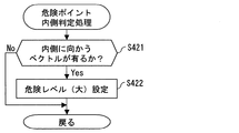
S42の危険ポイント内側判定処理について、図12に示すフローチャートを用いて説明する。この危険ポイント内側判定処理は、危険判定範囲分割処理において二分割された危険ポイントに対応する危険判定範囲のうち、自車両からの距離の短い(一般に、画面中央に対して内側に位置する)一方の危険判定範囲内の移動ベクトルについて判定するものである。 The risk point inside determination process in S42 will be described with reference to the flowchart shown in FIG. This risk point inside determination process is a short distance from the host vehicle (generally located inside the center of the screen) of the risk determination range corresponding to the risk point divided into two in the risk determination range division process. The movement vector within the risk determination range is determined.
S421では、内側に向かうベクトル(すなわち、自車両へ向かう移動ベクトル)が有るか否かを判定する。ここで、肯定判定される場合にはS422へ処理を進め、否定判定される場合には本処理を終了する。S422では、危険レベルとして「大」を設定する。 In S421, it is determined whether or not there is a vector that is directed inward (that is, a movement vector that is directed toward the host vehicle). If the determination is affirmative, the process proceeds to S422. If the determination is negative, the process ends. In S422, “Large” is set as the danger level.
図11のS43では、S42の危険ポイント内側判定処理において、危険レベル「大」が設定されたか否かを判定する。ここで、肯定判定される場合にはS44において、(危険度「大」)の警告処理を行う。 In S43 of FIG. 11, it is determined whether or not the danger level “high” is set in the danger point inside determination process of S42. If the determination is affirmative, a warning process of (risk level “high”) is performed in S44.
例えば、警告処理として、乗員に対して自車両の進行方向に危険レベルの高い物体が存在する旨を表示装置60に表示したり、スピーカ70から警報を出力したりする。これにより、危険な物体の存在を乗員に知らせることができる。
For example, as a warning process, the
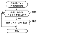
続いて、S45における危険ポイント外側判定処理について、図13に示すフローチャートを用いて説明する。この危険ポイント外側判定処理は、危険判定範囲分割処理において二分割された危険ポイントに対応する危険判定範囲のうち、自車両からの距離の長い(一般に、画面中央に対して外側に位置する)他方の危険判定範囲内の移動ベクトルについて判定するものである。 Next, the risk point outside determination process in S45 will be described with reference to the flowchart shown in FIG. The risk point outside determination process is a risk determination range corresponding to the risk point divided into two in the risk determination range division process, and has a long distance from the host vehicle (generally located outside the center of the screen). The movement vector within the risk determination range is determined.
S451では、内側に向かうベクトル(すなわち、前述した一方の危険判定範囲へ向かう移動ベクトル)が有るか否かを判定する。ここで、肯定判定される場合にはS452へ処理を進め、否定判定される場合には本処理を終了する。S452では、危険レベルとして「小」を設定する。 In S451, it is determined whether or not there is a vector inward (that is, a movement vector toward one of the risk determination ranges described above). If the determination is affirmative, the process proceeds to S452, and if the determination is negative, the process ends. In S452, “small” is set as the danger level.
図11のS46では、S45の危険ポイント外側判定処理において、危険レベル「小」が設定されたか否かを判定する。ここで、肯定判定される場合にはS47において、(危険度「小」)の警告処理を行う。 In S46 of FIG. 11, it is determined whether or not the danger level “low” is set in the danger point outside determination process of S45. If the determination is affirmative, a warning process of (risk level “low”) is performed in S47.
このように、前述の警告処理では、画面中央に対して外側よりも内側に位置する危険判定範囲に対して高い危険レベルを設定し、この危険レベルの高低に応じた警報を発生する。 Thus, in the warning process described above, a high danger level is set for the danger determination range located inside the outside relative to the center of the screen, and an alarm corresponding to the level of the danger level is generated.
すなわち、自車両からの距離が短い危険判定範囲に写し出される物体ほど、自車両に対して近い位置に存在するため、その物体の危険度は高い。従って、分割された危険判定範囲毎に、自車両からの距離が短くなるに従って高い危険レベルを設定し、この危険レベルの高低に応じた警報を発生することで、危険度に応じた警報を発生することができる。なお、S44における警告処理が実行されている場合には、本警告処理を行わないようにするとよい。 That is, an object that is projected in the danger determination range with a short distance from the host vehicle is present at a position closer to the host vehicle, and thus the risk level of the object is high. Therefore, for each divided risk judgment range, a higher danger level is set as the distance from the host vehicle becomes shorter, and an alarm according to the level of the danger level is generated, thereby generating an alarm according to the danger level. can do. In addition, when the warning process in S44 is performed, it is good not to perform this warning process.
このように、危険ポイントに対応する危険判定処理においては、1つの危険判定範囲に対して危険判定範囲毎に異なる判定条件を設定し、この異なる判定条件に基づいて危険判定を行っている。すなわち、内側危険判定処理においては、自車両へ向かう移動ベクトルの存在有無を判定条件としているため、例えば、横断歩道や交差点から飛び出してくる歩行者や軽車両等の危険な進入物体の存在有無を判定することができる。また、外側危険判定処理においては、内側危険判定処理において判定対象とした一方の危険判定範囲へ向かう移動ベクトルの存在有無を判定条件としているため、危険ポイントに進入した進入物体の存在有無を判定することができる。 Thus, in the risk determination process corresponding to the risk point, different determination conditions are set for each risk determination range for one risk determination range, and the risk determination is performed based on the different determination conditions. In other words, in the inside risk determination process, the presence / absence of a movement vector toward the host vehicle is used as a determination condition. For example, the presence / absence of a dangerous approaching object such as a pedestrian or light vehicle jumping out from a crosswalk or an intersection is detected. Can be determined. Further, in the outside risk determination process, the presence / absence of a moving vector toward the one risk determination range that is the determination target in the inside risk determination process is used as a determination condition. be able to.
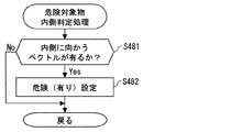
続いて、S48の危険対象物内側判定処理について、図14に示すフローチャートを用いて説明する。この危険対象物内側判定処理は、二分割された危険対象物に対応する危険判定範囲のうち、自車両からの距離の短い(一般に、画面中央に対して内側に位置する)一方の危険判定範囲内の移動ベクトルについて判定するものである。 Next, the dangerous object inside determination process in S48 will be described using the flowchart shown in FIG. This dangerous object inside determination process is performed in one of the danger determination ranges corresponding to the dangerous object divided into two, which is short of the distance from the own vehicle (generally located on the inside of the screen center). Are determined for the movement vector.
S481では、内側に向かうベクトル(すなわち、自車両へ向かう移動ベクトル)が有るか否かを判定する。ここで、肯定判定される場合にはS482へ処理を進め、否定判定される場合には本処理を終了する。S482では、危険「有り」を設定する。 In S481, it is determined whether or not there is a vector inward (that is, a movement vector toward the host vehicle). If the determination is affirmative, the process proceeds to S482. If the determination is negative, the process ends. In S482, the danger “present” is set.
図11のS49では、S48の危険対象物内側判定処理において、危険「有り」が設定されたか否かを判定する。ここで、肯定判定される場合にはS50において、前述の警告処理を行う。 In S49 of FIG. 11, it is determined whether or not the danger “present” is set in the dangerous object inside determination process of S48. If the determination is affirmative, the warning process described above is performed in S50.
続いて、S51における危険対象物外側判定処理について、図15に示すフローチャートを用いて説明する。この危険対象物外側判定処理は、危険判定範囲分割処理において二分割された危険対象物に対応する危険判定範囲のうち、自車両からの距離の長い(一般に、画面中央に対して外側に位置する)他方の危険判定範囲内の移動ベクトルについて判定するものである。 Next, the dangerous object outside determination process in S51 will be described with reference to the flowchart shown in FIG. This dangerous object outside determination process is a long distance from the host vehicle (generally located outside the center of the screen) in the risk determination range corresponding to the dangerous object divided in two in the risk determination range dividing process. ) A movement vector within the other risk determination range is determined.
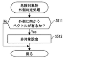
S511では、外側に向かうベクトル(すなわち、自車両から離れる方向へ向かう移動ベクトル)が有るか否かを判定する。ここで、肯定判定される場合にはS512へ処理を進め、否定判定される場合には本処理を終了する。S512では、危険対象物に対応する他方の危険判定範囲を「非対象」として設定する。 In S511, it is determined whether or not there is a vector directed outward (that is, a movement vector directed in a direction away from the host vehicle). If the determination is affirmative, the process proceeds to S512. If the determination is negative, the process ends. In S512, the other risk determination range corresponding to the dangerous object is set as “non-target”.
図11のS52では、S51の危険対象物外側判定処理において、「非対象」の設定がなされたか否かを判定する。ここで、肯定判定される場合にはS53において、他方の危険判定範囲を危険判定の対象範囲から除外する処理を行う。 In S52 of FIG. 11, it is determined whether or not “non-target” has been set in the dangerous object outside determination process of S51. If the determination is affirmative, in S53, the other risk determination range is excluded from the risk determination target range.
このように、危険対象物に対応する危険判定処理においても、1つの危険判定範囲に対して危険判定範囲毎に異なる判定条件を設定し、この異なる判定条件に基づいて危険判定を行っている。すなわち、内側危険判定処理においては、自車両へ向かう移動ベクトルの存在有無を判定条件としているため、例えば、歩行者、軽車両、他車両等の危険対象物の存在有無を判定することができる。また、外側危険判定処理においては、自車両から離れる方向へ向かう移動ベクトルの存在有無を判定条件としているため、危険対象物が存在しない危険判定範囲を判定しないようにすることができる。 Thus, also in the risk determination process corresponding to the dangerous object, different determination conditions are set for each risk determination range for one risk determination range, and the risk determination is performed based on the different determination conditions. That is, in the inside risk determination process, the presence / absence of a moving vector toward the host vehicle is used as a determination condition, and therefore the presence / absence of a dangerous object such as a pedestrian, a light vehicle, or another vehicle can be determined. Further, in the outside risk determination process, the presence / absence of a movement vector that moves away from the host vehicle is used as a determination condition, so that it is possible to prevent determination of a risk determination range in which no dangerous object exists.
このように、本実施形態の物体危険判定装置は、画像上における視点の位置を基準として危険判定の対象範囲とすべき危険判定範囲を設定し、瞳孔の開き度合いに基づいて危険判定範囲内に写し出される物体(危険ポイント、若しくは移動物体)を特定する。そして、危険判定範囲内に写し出される物体の移動ベクトルに基づいて、危険ポイントや移動物体に応じた危険判定を行う。 As described above, the object risk determination device according to the present embodiment sets a risk determination range that should be a target range for risk determination based on the position of the viewpoint on the image, and is within the risk determination range based on the degree of pupil opening. Specify the object (danger point or moving object) to be projected. Then, based on the movement vector of the object projected within the danger determination range, the danger determination according to the danger point or the moving object is performed.
これにより、横断歩道や交差点等の危険ポイントに進入した歩行者や軽車両等の進入物体の存在有無を判定することができる。また、自車両へ向かってくる歩行者、軽車両、他車両等の移動物体の存在有無を判定することができる。その結果、物体に応じた危険判定を的確に行うことが可能となる。 Accordingly, it is possible to determine the presence or absence of an entering object such as a pedestrian or a light vehicle that has entered a danger point such as a pedestrian crossing or an intersection. In addition, it is possible to determine the presence or absence of moving objects such as pedestrians, light vehicles, and other vehicles coming toward the host vehicle. As a result, it is possible to accurately determine the danger according to the object.
(変形例1)
本実施形態の危険判定処理は、二分割した危険判定範囲毎に危険判定を行うものであるが、危険判定範囲を分割することなく危険判定を行う場合には、次のような危険判定を行ってもよい。
(Modification 1)
The risk determination process of the present embodiment performs risk determination for each of the divided risk determination ranges. However, when risk determination is performed without dividing the risk determination range, the following risk determination is performed. May be.
危険ポイントに対応する危険判定範囲においては、危険判定範囲の境界の内側へ向かう移動ベクトルの始点、又は/及び終点が境界エリア内に位置するときに、危険判定範囲へ進入した危険な進入物体が存在すると判定する。 In the danger judgment range corresponding to the danger point, when the start point or / and the end point of the movement vector toward the inside of the border of the danger judgment range is located in the boundary area, a dangerous approaching object that has entered the danger judgment range is present. It is determined that it exists.
また、移動物体(危険対象物)に対応する危険判定範囲においては、移動ベクトルの始点、又は/及び終点が境界エリア内に位置するときに、危険判定範囲から自車両へ向かう危険な移動物体が存在すると判定する。 Further, in the danger determination range corresponding to the moving object (dangerous object), when the start point or / and the end point of the movement vector is located in the boundary area, a dangerous moving object heading from the danger determination range toward the host vehicle is detected. It is determined that it exists.
これにより、移動ベクトルが境界エリアを跨いだタイミングで危険な進入物体や危険対象物が存在すると判定されるため、この危険判定の判定結果に応じて警告処理を行う場合、煩わしい警告や警報を発生しないようにすることができる。 As a result, since it is determined that there is a dangerous approaching object or dangerous object at the timing when the movement vector crosses the boundary area, a troublesome warning or warning is generated when warning processing is performed according to the determination result of this risk determination. You can avoid it.
(変形例2)
本実施形態の危険判定範囲分割処理では、危険判定範囲を二分割しているが、さらに、その分割数を増やしてもよい。さらに、本実施形態と同様に、分割された危険判定範囲毎に自車両からの距離が短くなるに従って高い危険レベルを設定してもよい。
(Modification 2)
In the risk determination range dividing process of the present embodiment, the risk determination range is divided into two, but the number of divisions may be further increased. Further, as in the present embodiment, a higher risk level may be set as the distance from the host vehicle becomes shorter for each divided risk determination range.
(変形例3)
本実施形態の危険ポイント内側判定処理において、自車両に向かう移動ベクトルが有ると判定され、さらに、その移動ベクトルが危険判定範囲から逸脱した後も自車両に向かう場合には、その移動ベクトルの物体を危険対象物として設定し、その危険対象物に対応する危険判定範囲を設定して、その危険判定範囲に対する危険判定処理を行うようにしてもよい。
(Modification 3)
In the danger point inside determination process of the present embodiment, it is determined that there is a movement vector toward the host vehicle, and if the movement vector goes to the host vehicle even after deviating from the danger determination range, the object of the movement vector May be set as a dangerous object, a danger determination range corresponding to the dangerous object may be set, and a danger determination process may be performed for the danger determination range.
(変形例4)
本実施形態では、図8に示した危険判定範囲設定処理において、乗員の瞳孔の開き度合いに基づいて乗員の視認した(危険判定範囲内に写し出される)物体を特定しているが、カーナビ50から出力される地点情報に基づく画像における位置を算出し、その位置が危険判定範囲内となる場合に、その危険判定範囲内に写し出される物体は、危険ポイントであると特定するようにしてもよい。
(Modification 4)
In the present embodiment, in the risk determination range setting process shown in FIG. 8, an object visually recognized by the occupant (projected in the risk determination range) is specified based on the degree of opening of the occupant's pupil. A position in the image based on the output point information may be calculated, and when the position falls within the danger determination range, an object that is projected within the danger determination range may be identified as a danger point.
これにより、地図データに含まれる道路データから、道路の分岐地点、合流地点、交差点、及び横断歩道等の危険地点に関する情報を取得して、危険判定範囲内に写し出される物体を特定することができる。 As a result, it is possible to acquire information related to danger points such as road branch points, merge points, intersections, and pedestrian crossings from the road data included in the map data, and to identify objects that are projected within the risk determination range. .
10 制御装置
20 視線認識装置
30 視線認識用カメラ
40 物体監視用カメラ
50 カーナビ
60 表示装置
70 スピーカ
100 物体危険判定装置
DESCRIPTION OF
Claims (14)
前記視線方向の風景の画像を撮影する撮像手段と、
前記視線方向に基づいて、前記画像における視点の位置を特定する視点特定手段と、
前記視点特定手段の特定する視点の位置を基準として、前記画像上に危険判定の対象範囲とすべき危険判定範囲を設定する危険判定範囲設定手段と、
前記瞳孔の開き度合いに基づいて、前記危険判定範囲内に写し出される物体を特定する物体特定手段と、
前記撮像手段の撮影した前回までの画像と今回の画像とに基づいて、前記危険判定範囲内に写し出される物体の移動ベクトルを算出する移動ベクトル算出手段と、
前記移動ベクトルに基づいて、前記物体特定手段によって特定される物体に応じた危険判定を行う危険判定手段を備えることを特徴とする物体危険判定装置。 Detecting means for detecting the eye gaze direction and the degree of pupil opening;
Imaging means for capturing an image of the landscape in the viewing direction;
Viewpoint identifying means for identifying the position of the viewpoint in the image based on the line-of-sight direction;
A risk determination range setting means for setting a risk determination range to be a risk determination target range on the image with reference to the viewpoint position specified by the viewpoint specification means;
Based on the degree of opening of the pupil, object specifying means for specifying an object to be projected within the risk determination range;
A movement vector calculation means for calculating a movement vector of an object projected in the risk determination range based on the previous image taken by the imaging means and the current image;
An object risk determination device comprising: a risk determination unit that performs a risk determination according to an object specified by the object specification unit based on the movement vector.
前記道路データ記憶手段の記憶する道路データから前記視線方向に存在する前記危険地点に関する情報を取得する危険地点情報取得手段とを備え、
前記物体特定手段は、前記瞳孔の開き度合い、及び前記危険地点情報取得手段の取得する前記危険地点に関する情報の少なくとも一方に基づいて、前記危険判定範囲内に写し出される物体を特定することを特徴とする請求項1記載の物体危険判定装置。 Road data storage means for storing road data including the type and position of a danger point where at least one of the dangers of at least one of a branch point, a merge point, an intersection, and a pedestrian crossing of the road is latent;
Danger point information acquisition means for acquiring information on the danger point existing in the line-of-sight direction from road data stored in the road data storage means,
The object specifying means specifies an object to be projected in the risk determination range based on at least one of the degree of opening of the pupil and the information on the dangerous point acquired by the dangerous point information acquiring means. The object danger judging device according to claim 1.
前記物体情報取得手段の取得した前記物体に関する情報に基づく前記画像上の位置が前記危険判定範囲内に位置する場合、又は/及び前記瞳孔の開き度合いが通常の開き度合い以上である場合、前記危険判定範囲内に写し出される物体は危険が潜在する危険地点であると特定し、
前記瞳孔の開き度合いが通常の開き度合いに満たない場合、前記危険判定範囲内に写し出される物体は移動物体であると特定することを特徴とする請求項1又は2記載の物体危険判定装置。 The object specifying means includes
When the position on the image based on the information related to the object acquired by the object information acquisition means is located within the danger determination range, or / and when the degree of opening of the pupil is greater than or equal to a normal degree of opening, the danger Identify the object to be projected within the judgment range as a danger point with potential danger,
3. The object risk determination device according to claim 1, wherein when the degree of opening of the pupil is less than a normal degree of opening, the object projected in the risk determination range is specified as a moving object.
前記物体情報取得手段の取得した前記物体に関する情報に基づく前記画像上の位置が前記危険判定範囲内に位置する場合、又は/及び前記瞳孔の開き度合いが通常の開き度合いを超える場合、前記危険判定範囲内に写し出される物体は危険が潜在する危険地点であると特定し、
前記瞳孔の開き度合いが通常の開き度合い以下の場合、前記危険判定範囲内に写し出される物体は移動物体であると特定することを特徴とする請求項1又は2記載の物体危険判定装置。 The object specifying means includes
When the position on the image based on the information related to the object acquired by the object information acquisition means is located within the danger determination range, or / and when the pupil opening degree exceeds a normal opening degree, the risk determination Identify the object to be projected within the range as a potential danger point,
3. The object risk determination device according to claim 1, wherein when the pupil opening degree is equal to or less than a normal opening degree, the object projected in the risk determination range is specified as a moving object.
前記移動ベクトル算出手段は、前記危険判定範囲追従手段によって追従された危険判定範囲内に写し出される物体の移動ベクトルを算出することを特徴とする請求項1〜4の何れか1項に記載の物体危険判定装置。 In accordance with the movement in the image photographed by the imaging means, the risk judgment range following means for following the setting position of the danger judgment range set by the danger judgment range setting means,
5. The object according to claim 1, wherein the movement vector calculation unit calculates a movement vector of an object projected in a danger determination range tracked by the danger determination range tracking unit. Risk judgment device.
前記危険判定手段は、前記移動ベクトルの方向成分から前記平均移動ベクトルの方向成分を除いた実移動ベクトルに基づいて危険判定を行うことを特徴とする請求項1〜6の何れか1項に記載の物体危険判定装置。 The movement vector calculation means further calculates an average movement vector indicating an average movement direction of movement vectors within the danger determination range;
7. The risk determination unit according to claim 1, wherein the risk determination unit performs the risk determination based on an actual movement vector obtained by removing a direction component of the average movement vector from a direction component of the movement vector. Object danger judgment device.
前記移動ベクトル算出手段は、前記境界の内側、及び前記境界エリア内の少なくとも一方の移動ベクトルの前記平均移動ベクトルを算出することを特徴とする請求項7記載の物体危険判定装置。 The risk determination range setting means sets a boundary area surrounding a boundary of the risk determination range when setting the risk determination range;
8. The object risk determination device according to claim 7, wherein the movement vector calculation means calculates the average movement vector of at least one of the movement vectors inside the boundary and in the boundary area.
前記危険判定手段は、
前記危険地点に対して、前記危険判定範囲に進入した移動ベクトルが存在するか否かを判定し、
前記移動物体に対して、前記危険判定範囲から前記移動体へ向かう移動ベクトルが存在するか否かを判定することを特徴とする請求項2〜8の何れか1項に記載の物体危険判定装置。 The imaging means is mounted on a moving body and captures an image of a landscape in the traveling direction of the moving body,
The risk determination means includes
It is determined whether or not there is a movement vector that has entered the risk determination range for the risk point,
The object risk determination apparatus according to any one of claims 2 to 8, wherein a determination is made as to whether or not a moving vector from the danger determination range toward the moving object exists for the moving object. .
前記危険判定手段は、前記複数に分割された危険判定範囲毎の異なる判定条件に基づいて、危険判定を行うことを特徴とする請求項9記載の物体危険判定装置。 A risk determination range dividing unit that divides the risk determination range into a plurality of angles at an angle in the image indicated by the average movement vector;
10. The object risk determination apparatus according to claim 9, wherein the risk determination means performs a risk determination based on different determination conditions for each of the plurality of risk determination ranges divided into a plurality.
前記危険判定手段は、
前記危険地点に対して、
前記二分割された危険判定範囲のうち、前記移動体からの距離が短い側に存在する一方の危険判定範囲においては、前記移動体へ向かう移動ベクトルが存在するか否かを判定条件とし、前記移動体へ向かう移動ベクトルが存在する場合に危険な進入物体が存在すると判定し、
前記二分割された危険判定範囲のうち、他方の危険判定範囲においては、前記一方の危険判定範囲へ向かう移動ベクトルが存在するか否かを判定条件とし、前記一方の危険判定範囲へ向かう移動ベクトルが存在する場合に危険な進入物体が存在すると判定し、
前記移動物体に対して、
前記二分割された危険判定範囲のうち、前記移動体からの距離が短い側に存在する一方の危険判定範囲においては、前記移動体へ向かう移動ベクトルが存在するか否かを判定条件とし、前記移動体へ向かう移動ベクトルが存在する場合に危険な移動物体が存在すると判定し、
前記二分割された危険判定範囲のうち、他方の危険判定範囲においては、前記移動体から離れる方向へ向かう移動ベクトルが存在するか否かを判定条件とし、前記移動体から離れる方向へ向かう移動ベクトルが存在する場合に前記他方の危険判定範囲を危険判定の対象範囲から除外すると判定することを特徴とする請求項10記載の物体危険判定装置。 The risk determination range dividing means divides the risk determination range into two ranges so that the number of the movement vectors is substantially equal,
The risk determination means includes
For the danger point,
Of the two divided risk determination ranges, in one risk determination range that exists on the short side from the moving body, whether or not there is a movement vector toward the moving body, the determination condition, When there is a movement vector toward the moving body, it is determined that a dangerous approaching object exists,
Of the two divided risk determination ranges, in the other risk determination range, a determination is made as to whether or not there is a movement vector toward the one risk determination range, and a movement vector toward the one risk determination range. If there is a dangerous approaching object,
For the moving object,
Of the two divided risk determination ranges, in one risk determination range that exists on the short side from the moving body, whether or not there is a movement vector toward the moving body, the determination condition, When there is a movement vector toward the moving body, it is determined that there is a dangerous moving object,
Of the two divided risk determination ranges, in the other risk determination range, a determination is made as to whether or not there is a movement vector that moves away from the moving body, and a movement vector that moves away from the moving body. 11. The object risk determination device according to claim 10, wherein the object risk determination range is determined to exclude the other risk determination range from the risk determination target range.
前記危険地点に対して、前記危険判定範囲の境界の内側へ向かう移動ベクトルの始点、又は/及び終点が前記境界エリア内に位置するときに、前記危険判定範囲へ進入した危険な進入物体が存在すると判定し、
前記移動物体に対して、前記移動ベクトルの始点、又は/及び終点が前記境界エリア内に位置するときに、前記危険判定範囲から前記移動体へ向かう危険な移動物体が存在すると判定することを特徴とする請求項9記載の物体危険判定装置。 The risk determination means includes
There is a dangerous approaching object that has entered the risk determination range when the start point and / or end point of the movement vector toward the inside of the boundary of the risk determination range is located within the boundary area with respect to the risk point Then,
When the start point or / and end point of the movement vector is located in the boundary area with respect to the moving object, it is determined that there is a dangerous moving object from the danger determination range toward the moving object. The object danger judgment device according to claim 9.
前記警報手段は、前記危険レベルの高低に応じた警報を発生することを特徴とする請求項13記載の物体危険判定装置。 The danger determination range dividing means includes a danger level setting means for setting a higher danger level as the distance from the moving body becomes shorter for each danger determination range,
14. The object danger determination device according to claim 13, wherein the alarm means generates an alarm corresponding to the level of the danger level.
Priority Applications (1)
| Application Number | Priority Date | Filing Date | Title |
|---|---|---|---|
| JP2004111103A JP4270010B2 (en) | 2004-04-05 | 2004-04-05 | Object danger judgment device |
Applications Claiming Priority (1)
| Application Number | Priority Date | Filing Date | Title |
|---|---|---|---|
| JP2004111103A JP4270010B2 (en) | 2004-04-05 | 2004-04-05 | Object danger judgment device |
Publications (2)
| Publication Number | Publication Date |
|---|---|
| JP2005293479A true JP2005293479A (en) | 2005-10-20 |
| JP4270010B2 JP4270010B2 (en) | 2009-05-27 |
Family
ID=35326304
Family Applications (1)
| Application Number | Title | Priority Date | Filing Date |
|---|---|---|---|
| JP2004111103A Expired - Fee Related JP4270010B2 (en) | 2004-04-05 | 2004-04-05 | Object danger judgment device |
Country Status (1)
| Country | Link |
|---|---|
| JP (1) | JP4270010B2 (en) |
Cited By (12)
| Publication number | Priority date | Publication date | Assignee | Title |
|---|---|---|---|---|
| JP2007153307A (en) * | 2005-11-09 | 2007-06-21 | Nissan Motor Co Ltd | Vehicle driving assist device and vehicle equipped with the same device |
| JP2008003762A (en) * | 2006-06-21 | 2008-01-10 | Honda Motor Co Ltd | Obstacle recognition determining device |
| JP2008071162A (en) * | 2006-09-14 | 2008-03-27 | Toyota Motor Corp | Sight-line end estimation device |
| WO2008041532A1 (en) * | 2006-09-25 | 2008-04-10 | Pioneer Corporation | Information providing apparatus, information terminal device, information providing method, information display method, information providing program, information display program and recording medium |
| JP2008282106A (en) * | 2007-05-08 | 2008-11-20 | Fujitsu Ltd | Method for detecting obstacle and obstacle detector |
| JP2009282592A (en) * | 2008-05-20 | 2009-12-03 | Hitachi Ltd | Vehicular outside world recognition device and vehicle system |
| JP2014054486A (en) * | 2012-09-14 | 2014-03-27 | Fujitsu Ltd | Steady gaze position detector and steady gaze position detecting method |
| KR101936629B1 (en) * | 2018-01-19 | 2019-01-09 | 엘지전자 주식회사 | Vehicle and control method for the same |
| US10479274B2 (en) | 2015-10-07 | 2019-11-19 | Lg Electronics Inc. | Vehicle and control method for the same |
| JP2020035437A (en) * | 2018-08-29 | 2020-03-05 | デンソー インターナショナル アメリカ インコーポレーテッド | Vehicle system, method to be implemented in vehicle system, and driver assistance system |
| US10964137B2 (en) | 2017-06-22 | 2021-03-30 | Mitsubishi Electric Corporation | Risk information collection device mounted on a vehicle |
| CN113780255A (en) * | 2021-11-12 | 2021-12-10 | 北京世纪好未来教育科技有限公司 | Danger assessment method, device, equipment and storage medium |
Citations (9)
| Publication number | Priority date | Publication date | Assignee | Title |
|---|---|---|---|---|
| JPH06107096A (en) * | 1992-09-25 | 1994-04-19 | Yazaki Corp | Forward monitoring method for vehicle |
| JPH06215300A (en) * | 1993-01-19 | 1994-08-05 | Mitsubishi Electric Corp | Dangerous status alarming device |
| JPH0761257A (en) * | 1993-08-26 | 1995-03-07 | Nissan Motor Co Ltd | Display device for vehicle |
| JPH11245683A (en) * | 1998-02-27 | 1999-09-14 | Nissan Motor Co Ltd | Information presenting device for vehicle |
| JPH11288341A (en) * | 1998-04-01 | 1999-10-19 | Canon Inc | Device and method for navigation |
| JP2001163082A (en) * | 1999-12-09 | 2001-06-19 | Mazda Motor Corp | Controller for movable body |
| JP2001195698A (en) * | 2000-01-07 | 2001-07-19 | Nissan Motor Co Ltd | Device for detecting pedestrian |
| JP2001199296A (en) * | 2000-01-17 | 2001-07-24 | Matsushita Electric Ind Co Ltd | Warning device, driver's seat having vibrating body, and mobile body equipped with warning device on vehicle |
| JP2003196664A (en) * | 2001-12-28 | 2003-07-11 | Honda Motor Co Ltd | Object detection device |
-
2004
- 2004-04-05 JP JP2004111103A patent/JP4270010B2/en not_active Expired - Fee Related
Patent Citations (9)
| Publication number | Priority date | Publication date | Assignee | Title |
|---|---|---|---|---|
| JPH06107096A (en) * | 1992-09-25 | 1994-04-19 | Yazaki Corp | Forward monitoring method for vehicle |
| JPH06215300A (en) * | 1993-01-19 | 1994-08-05 | Mitsubishi Electric Corp | Dangerous status alarming device |
| JPH0761257A (en) * | 1993-08-26 | 1995-03-07 | Nissan Motor Co Ltd | Display device for vehicle |
| JPH11245683A (en) * | 1998-02-27 | 1999-09-14 | Nissan Motor Co Ltd | Information presenting device for vehicle |
| JPH11288341A (en) * | 1998-04-01 | 1999-10-19 | Canon Inc | Device and method for navigation |
| JP2001163082A (en) * | 1999-12-09 | 2001-06-19 | Mazda Motor Corp | Controller for movable body |
| JP2001195698A (en) * | 2000-01-07 | 2001-07-19 | Nissan Motor Co Ltd | Device for detecting pedestrian |
| JP2001199296A (en) * | 2000-01-17 | 2001-07-24 | Matsushita Electric Ind Co Ltd | Warning device, driver's seat having vibrating body, and mobile body equipped with warning device on vehicle |
| JP2003196664A (en) * | 2001-12-28 | 2003-07-11 | Honda Motor Co Ltd | Object detection device |
Cited By (15)
| Publication number | Priority date | Publication date | Assignee | Title |
|---|---|---|---|---|
| JP2007153307A (en) * | 2005-11-09 | 2007-06-21 | Nissan Motor Co Ltd | Vehicle driving assist device and vehicle equipped with the same device |
| JP2008003762A (en) * | 2006-06-21 | 2008-01-10 | Honda Motor Co Ltd | Obstacle recognition determining device |
| JP4722777B2 (en) * | 2006-06-21 | 2011-07-13 | 本田技研工業株式会社 | Obstacle recognition judgment device |
| US7859652B2 (en) | 2006-09-14 | 2010-12-28 | Toyota Jidosha Kabushiki Kaisha | Sight-line end estimation device and driving assist device |
| JP2008071162A (en) * | 2006-09-14 | 2008-03-27 | Toyota Motor Corp | Sight-line end estimation device |
| KR101095234B1 (en) * | 2006-09-14 | 2011-12-20 | 도요타지도샤가부시키가이샤 | Sight-line end estimation device and driving assist device |
| WO2008041532A1 (en) * | 2006-09-25 | 2008-04-10 | Pioneer Corporation | Information providing apparatus, information terminal device, information providing method, information display method, information providing program, information display program and recording medium |
| JP2008282106A (en) * | 2007-05-08 | 2008-11-20 | Fujitsu Ltd | Method for detecting obstacle and obstacle detector |
| JP2009282592A (en) * | 2008-05-20 | 2009-12-03 | Hitachi Ltd | Vehicular outside world recognition device and vehicle system |
| JP2014054486A (en) * | 2012-09-14 | 2014-03-27 | Fujitsu Ltd | Steady gaze position detector and steady gaze position detecting method |
| US10479274B2 (en) | 2015-10-07 | 2019-11-19 | Lg Electronics Inc. | Vehicle and control method for the same |
| US10964137B2 (en) | 2017-06-22 | 2021-03-30 | Mitsubishi Electric Corporation | Risk information collection device mounted on a vehicle |
| KR101936629B1 (en) * | 2018-01-19 | 2019-01-09 | 엘지전자 주식회사 | Vehicle and control method for the same |
| JP2020035437A (en) * | 2018-08-29 | 2020-03-05 | デンソー インターナショナル アメリカ インコーポレーテッド | Vehicle system, method to be implemented in vehicle system, and driver assistance system |
| CN113780255A (en) * | 2021-11-12 | 2021-12-10 | 北京世纪好未来教育科技有限公司 | Danger assessment method, device, equipment and storage medium |
Also Published As
| Publication number | Publication date |
|---|---|
| JP4270010B2 (en) | 2009-05-27 |
Similar Documents
| Publication | Publication Date | Title |
|---|---|---|
| JP6648411B2 (en) | Processing device, processing system, processing program and processing method | |
| US10387733B2 (en) | Processing apparatus, processing system, and processing method | |
| JP6416293B2 (en) | Method of tracking a target vehicle approaching a car by a car camera system, a camera system, and a car | |
| US20150332103A1 (en) | Processing apparatus, computer program product, and processing method | |
| JP2014181927A (en) | Information provision device, and information provision program | |
| JP2008123462A (en) | Object detector | |
| US9626866B2 (en) | Active warning system using the detection of driver awareness of traffic signs | |
| JP5898001B2 (en) | Vehicle periphery monitoring device | |
| JP4270010B2 (en) | Object danger judgment device | |
| JP4483305B2 (en) | Vehicle periphery monitoring device | |
| JPWO2015177864A1 (en) | Signal recognition device and signal recognition method | |
| JP6129268B2 (en) | Vehicle driving support system and driving support method | |
| JP2009033743A (en) | Method for recognition of object | |
| JP2015207163A (en) | State estimation device and state estimation program | |
| JP2009231938A (en) | Surrounding monitoring device for vehicle | |
| JP6296684B2 (en) | Driving assistance device | |
| JP2017129973A (en) | Driving support apparatus and driving support method | |
| JP2021140423A (en) | Vehicle controller | |
| JP4277678B2 (en) | Vehicle driving support device | |
| JP2009146153A (en) | Moving object detection device, moving object detection method and moving object detection program | |
| JP4345526B2 (en) | Object monitoring device | |
| US20230249686A1 (en) | Controller, method, and computer program for vehicle control | |
| JP2008305283A (en) | Drive support apparatus and drive support method | |
| WO2016088227A1 (en) | Video display device and method | |
| JP2018049486A (en) | Driver state determination device and operation support system |
Legal Events
| Date | Code | Title | Description |
|---|---|---|---|
| A621 | Written request for application examination |
Free format text: JAPANESE INTERMEDIATE CODE: A621 Effective date: 20060519 |
|
| A977 | Report on retrieval |
Free format text: JAPANESE INTERMEDIATE CODE: A971007 Effective date: 20080807 |
|
| A131 | Notification of reasons for refusal |
Free format text: JAPANESE INTERMEDIATE CODE: A131 Effective date: 20080902 |
|
| A521 | Written amendment |
Free format text: JAPANESE INTERMEDIATE CODE: A523 Effective date: 20081020 |
|
| TRDD | Decision of grant or rejection written | ||
| A01 | Written decision to grant a patent or to grant a registration (utility model) |
Free format text: JAPANESE INTERMEDIATE CODE: A01 Effective date: 20090203 |
|
| A01 | Written decision to grant a patent or to grant a registration (utility model) |
Free format text: JAPANESE INTERMEDIATE CODE: A01 |
|
| A61 | First payment of annual fees (during grant procedure) |
Free format text: JAPANESE INTERMEDIATE CODE: A61 Effective date: 20090216 |
|
| FPAY | Renewal fee payment (event date is renewal date of database) |
Free format text: PAYMENT UNTIL: 20120306 Year of fee payment: 3 |
|
| R150 | Certificate of patent or registration of utility model |
Ref document number: 4270010 Country of ref document: JP Free format text: JAPANESE INTERMEDIATE CODE: R150 Free format text: JAPANESE INTERMEDIATE CODE: R150 |
|
| FPAY | Renewal fee payment (event date is renewal date of database) |
Free format text: PAYMENT UNTIL: 20120306 Year of fee payment: 3 |
|
| FPAY | Renewal fee payment (event date is renewal date of database) |
Free format text: PAYMENT UNTIL: 20130306 Year of fee payment: 4 |
|
| FPAY | Renewal fee payment (event date is renewal date of database) |
Free format text: PAYMENT UNTIL: 20140306 Year of fee payment: 5 |
|
| R250 | Receipt of annual fees |
Free format text: JAPANESE INTERMEDIATE CODE: R250 |
|
| R250 | Receipt of annual fees |
Free format text: JAPANESE INTERMEDIATE CODE: R250 |
|
| R250 | Receipt of annual fees |
Free format text: JAPANESE INTERMEDIATE CODE: R250 |
|
| R250 | Receipt of annual fees |
Free format text: JAPANESE INTERMEDIATE CODE: R250 |
|
| R250 | Receipt of annual fees |
Free format text: JAPANESE INTERMEDIATE CODE: R250 |
|
| R250 | Receipt of annual fees |
Free format text: JAPANESE INTERMEDIATE CODE: R250 |
|
| R250 | Receipt of annual fees |
Free format text: JAPANESE INTERMEDIATE CODE: R250 |
|
| LAPS | Cancellation because of no payment of annual fees |
