JP2005293376A - Onboard camera - Google Patents
Onboard camera Download PDFInfo
- Publication number
- JP2005293376A JP2005293376A JP2004109333A JP2004109333A JP2005293376A JP 2005293376 A JP2005293376 A JP 2005293376A JP 2004109333 A JP2004109333 A JP 2004109333A JP 2004109333 A JP2004109333 A JP 2004109333A JP 2005293376 A JP2005293376 A JP 2005293376A
- Authority
- JP
- Japan
- Prior art keywords
- vehicle
- steering angle
- angle
- vehicle speed
- view
- Prior art date
- Legal status (The legal status is an assumption and is not a legal conclusion. Google has not performed a legal analysis and makes no representation as to the accuracy of the status listed.)
- Pending
Links
- 238000001514 detection method Methods 0.000 claims description 4
- 230000007423 decrease Effects 0.000 claims 1
- 238000000034 method Methods 0.000 description 20
- 238000004891 communication Methods 0.000 description 6
- 238000010586 diagram Methods 0.000 description 4
- 238000006243 chemical reaction Methods 0.000 description 2
- 238000007792 addition Methods 0.000 description 1
Images
Landscapes
- Focusing (AREA)
- Lens Barrels (AREA)
- Automatic Focus Adjustment (AREA)
- Traffic Control Systems (AREA)
Abstract
Description
本発明は、車両の外部を撮影して運転者に見せて運転支援等を行うための車載カメラの技術分野に属する。 The present invention belongs to the technical field of an in-vehicle camera for photographing the outside of a vehicle and showing it to a driver for driving assistance and the like.
従来の車載カメラは、車両の速度計の信号に従って、カメラのズームレンズを駆動して、車両の速度に応じてズームインあるいはズームアウトを行う。(例えば、特許文献1参照。)。
しかしながら、従来にあっては、車載カメラを車両の車速に応じてズームを行うものでは、カーブ路において道路脇を映すことになり、見づらい画像になってしまう。 However, in the past, when the in-vehicle camera is zoomed according to the vehicle speed, the side of the road is projected on a curved road, resulting in an image that is difficult to see.
本発明は、上記問題点に着目してなされたもので、その目的とするところは、
カーブ路でも遠方の車両や障害物を映せるようにできる車載カメラを提供することにある。
The present invention was made paying attention to the above-mentioned problems, and the object is as follows.
The object is to provide an in-vehicle camera that can show distant vehicles and obstacles even on curved roads.
上記目的を達成するため、本発明では、車両に搭載して前方または後方を監視する車載カメラにおいて、車両の速度を検知する速度検知手段と、車両のステアリング舵角を検知する舵角検知手段と、車両の速度とステアリング舵角に従ってズームレンズを制御する画角制御手段とを具備し、車両の速度とステアリング舵角に応じて焦点距離を変えることを特徴とする。 In order to achieve the above object, according to the present invention, in an in-vehicle camera that is mounted on a vehicle and monitors front or rear, a speed detection unit that detects the speed of the vehicle, a steering angle detection unit that detects a steering angle of the vehicle, And an angle-of-view control means for controlling the zoom lens according to the vehicle speed and the steering angle, and the focal length is changed according to the vehicle speed and the steering angle.
よって、車載カメラを車両の車速に応じてズームを行うが、ステアリングの舵角に応じてズームを戻すようにすることにより、カーブ路でも遠方の車両や障害物を映すことができる。 Therefore, the in-vehicle camera is zoomed according to the vehicle speed of the vehicle, but by returning the zoom according to the steering angle of the steering wheel, a distant vehicle or an obstacle can be reflected even on a curved road.
以下、本発明の車載カメラを実現する実施の形態を、請求項1,2に係る発明に対応する実施例1に基づいて説明する。 Hereinafter, an embodiment for realizing an in-vehicle camera of the present invention will be described based on Example 1 corresponding to the first and second aspects of the invention.
まず、構成を説明する。
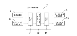
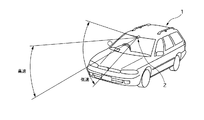
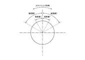
図1は実施例1の車載カメラの制御部分のブロック図である。図2〜図4は実施例1の車載カメラの制御処理の流れを示すフローチャート図である。図5は実施例1の車載カメラの車速と画角の関係を示す説明図である。図6は実施例1の車載カメラを車両に取り付けた状態を示す斜視図である。図7は実施例1の車載カメラの制御で使用するステアリング舵角の説明図である。
車両速度計3(速度検知手段に相当する)は、車両の速度に比例したレートのパルスを発生する。
ステアリング舵角センサー14(舵角検知手段に相当する)は、ハンドルに取り付けた舵角センサで、CAN等の通信によりズーム制御装置に入力される。
ズーム制御装置4は、入力I/F41とマイクロコンピュータ42及び出力I/F43を主な構成としている。
First, the configuration will be described.
FIG. 1 is a block diagram of a control portion of the in-vehicle camera according to the first embodiment. 2 to 4 are flowcharts illustrating the flow of control processing of the in-vehicle camera according to the first embodiment. FIG. 5 is an explanatory diagram showing the relationship between the vehicle speed and the angle of view of the in-vehicle camera of the first embodiment. FIG. 6 is a perspective view illustrating a state in which the vehicle-mounted camera according to the first embodiment is attached to the vehicle. FIG. 7 is an explanatory diagram of the steering angle used in the control of the in-vehicle camera according to the first embodiment.
A vehicle speedometer 3 (corresponding to a speed detection means) generates pulses at a rate proportional to the speed of the vehicle.
A steering rudder angle sensor 14 (corresponding to a rudder angle detecting means) is a rudder angle sensor attached to a steering wheel, and is input to the zoom control device through communication such as CAN.
The
入力I/F41は、車両速度計3のパルス信号とステアリング舵角センサー14の通信信号をマイクロコンピュータ42の入力に合わす為の変換を行う。
マイクロコンピュータ42は、車両速度計3のパルス信号より車両速度を計算し、ステアリング舵角センサー14の通信信号を受信して舵角値を取り込み、この2つのパラメータより演算してズームレンズの画角を求め、ズームレンズ駆動装置5とフォーカス駆動装置15を駆動する信号を作成する。
出力I/F43は、マイクロコンピュータ42から出力したズームレンズ駆動制御信号とフォーカス駆動制御信号をズームレンズ駆動装置5とフォーカス駆動装置15の入力に合わす変換を行う。
The input I /
The
The output I /
ズームレンズ駆動装置5(マイクロコンピュータ42とともに画角制御手段に相当する)は、ズームレンズ駆動制御信号によりバリエータレンズを移動させる駆動系である。
フォーカス駆動装置15は、フォーカス駆動制御信号によりフォーカシングレンズを移動させる駆動系である。
The zoom lens driving device 5 (corresponding to the angle of view control means together with the microcomputer 42) is a drive system that moves the variator lens by a zoom lens drive control signal.
The
次に、作用を説明する。
[車両速度及びステアリング舵角による画角制御処理]
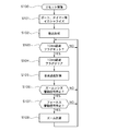
図2に示すのは、実施例1の車載カメラ2のマイクロコンピュータ42で実行される画角制御処理の流れを示すフローチャートで、以下、各ステップについて説明する。
電源ON後リセット解除するとステップS100に飛び、リセットルーチンを実行する。
Next, the operation will be described.
[View angle control processing based on vehicle speed and steering angle]
FIG. 2 is a flowchart showing the flow of the angle-of-view control process executed by the
When the reset is released after the power is turned on, the process jumps to step S100 to execute the reset routine.
ステップS101では、ポート、タイマー、割込マスク等のレジスタの初期化を行う。立下りエッジによるインプットキャプチャー割込と1msタイマー割込及びステアリング舵角センサー14との通信を設定する。
In step S101, registers such as ports, timers, and interrupt masks are initialized. Communication with the input capture interrupt by the falling edge, the 1 ms timer interrupt, and the
ステップS102では、割込禁止から割込許可し、割込を受け入れる様にする。
以下、ステップS103からステップS108迄は、メインルーチンで繰り返し実行する。
In step S102, interrupt is permitted from interrupt prohibition, and the interrupt is accepted.
Thereafter, steps S103 to S108 are repeatedly executed in the main routine.
ステップS103では、10ms経過フラグがセットされているか判断し、セットされているならばステップS104に進み、セットされていないならばステップS103をループする。 In step S103, it is determined whether or not the 10 ms elapsed flag is set. If it is set, the process proceeds to step S104, and if it is not set, step S103 is looped.
ステップS104では、10ms経過フラグをクリアする。 In step S104, the 10 ms elapsed flag is cleared.
ステップS105では、車両速度計3の出力パルスの立下りエッジによるインプットキャプチャー割込により取り込んだインプットキャプチャー値T1と割込回数カウンタ値N1を元に車両速度を求める。この車両速度は、車両速度V=A(N1-N2)/(T1-T2)の式で計算する。ここで、Aはパルス周期より車両速度に変換する係数であり、T2は前回車両速度計算した時のインプットキャプチャー値T1であり、N2は前回車両速度計算した時の割込回数カウンタ値N1である。
In step S105, the vehicle speed is obtained based on the input capture value T1 and the interrupt counter value N1 captured by the input capture interrupt at the falling edge of the output pulse of the
ステップS106では、ズームレンズ駆動制御信号が停止しているかを判断し、停止しているならばステップS107に進み、停止していないならばステップS103に進む。 In step S106, it is determined whether the zoom lens drive control signal is stopped. If it is stopped, the process proceeds to step S107, and if not, the process proceeds to step S103.
ステップS107では、フォーカス駆動信号が停止しているかを判断し、停止しているならばステップS108に進み、停止していないならばステップS103に進む。 In step S107, it is determined whether the focus drive signal is stopped. If it is stopped, the process proceeds to step S108, and if not stopped, the process proceeds to step S103.
ステップS108では、車両速度計3の出力パルスより求めた車両速度とステアリング舵角センサー14より受信した舵角値のこの2つのパラメータより画角を求める。この画角よりズームレンズ駆動制御信号とフォーカス駆動制御信号の指令値を計算し、ステップS103へ進む。
In step S108, the angle of view is obtained from the two parameters of the vehicle speed obtained from the output pulse of the
[車両速度に関する割込み処理]
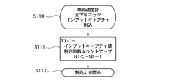
図3に示すのは、実施例1の車載カメラ2のマイクロコンピュータ42で実行される画角制御処理に対する車両速度に関する割込み処理の流れを示すフローチャートで、以下、各ステップについて説明する。
[Interrupt processing for vehicle speed]
FIG. 3 is a flowchart showing a flow of an interrupt process related to the vehicle speed with respect to the view angle control process executed by the
車両速度計3の出力パルスの立下りエッジがインプットキャプチャー入力に入ると、インプットキャプチャー割込が発生し、メインルーチン(ステップS100〜S108)のプログラムを一時中断してステップS110に飛ぶ。
When the falling edge of the output pulse of the
ステップS111では、インプットキャプチャー値をRAMであるT1に記憶し、RAMである割込回数カウンタ値N1をカウントアップする。 In step S111, the input capture value is stored in T1, which is a RAM, and the interrupt counter value N1, which is a RAM, is counted up.
ステップS112では、割込みより戻り、一時中断したメインルーチンのプログラムの実行を再開する。 In step S112, the program returns from the interrupt and resumes the execution of the temporarily interrupted main routine program.
[ステアリング舵角に関する割込み処理]
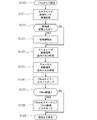
図4に示すのは、実施例1の車載カメラ2のマイクロコンピュータ42で実行される画角制御処理に対するステアリング舵角に関する割込み処理の流れを示すフローチャートで、以下、各ステップについて説明する。
[Interrupt handling for steering angle]
FIG. 4 is a flowchart showing a flow of interrupt processing relating to the steering angle with respect to the angle-of-view control processing executed by the
1msタイマーが1ms経過時、タイマー割込みが発生しステップS120に飛ぶ。 When the 1 ms timer elapses, a timer interrupt occurs and the process jumps to step S120.
ステップS121では、通信で送られてくるステアリング舵角センサー14の舵角値を受信したかチェックする。
In step S121, it is checked whether the steering angle value of the
ステップS122では、ステアリング舵角センサー14からの舵角値を受信したかどうかを判断し、受信したならばステップS123に進み、受信しないならばステップS124に進む。
In step S122, it is determined whether or not the steering angle value from the
ステップS123では、受信した舵角値をRAMに記憶する。 In step S123, the received steering angle value is stored in the RAM.
ステップS124では、ズームレンズ駆動制御信号の指令値と現在の移動位置を比較してずれている時、指令値に達するまでズームレンズ駆動制御信号を動作させる。 In step S124, when the command value of the zoom lens drive control signal is deviated from the current movement position, the zoom lens drive control signal is operated until the command value is reached.
ステップS125では、フォーカス駆動制御信号の指令値と現在の移動位置を比較してずれている時、指令値に達するまでフォーカス駆動制御信号を動作させる。 In step S125, when the command value of the focus drive control signal is different from the current movement position, the focus drive control signal is operated until the command value is reached.
ステップS126では、10msタイマーをカウントアップする。 In step S126, the 10 ms timer is counted up.
ステップS127では、10ms経過したか判断し、経過したならばステップS128に進み、経過しないならばステップS129に進む。 In step S127, it is determined whether 10 ms has elapsed. If it has elapsed, the process proceeds to step S128, and if not, the process proceeds to step S129.
ステップS128では、10msタイマーをクリアし、10ms経過フラグをセットする。 In step S128, the 10 ms timer is cleared and a 10 ms elapsed flag is set.
ステップS129では、割込より戻り、一時中断したメインルーチンのプログラムの実行を再開する。 In step S129, the program returns from the interrupt and resumes the execution of the temporarily interrupted main routine program.
[画角制御]
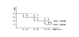
実施例1の画角制御処理について、図5を参照して説明する。
図5に示すように、ステアリング舵角センサー14の舵角値及び車両速度共にヒステリシスを設け、ハンチングを防止する。
ステアリング舵角センサー14の舵角値が設定値1未満の時で車両速度が30km/h未満の時、画角は、最大値の24度にする。
車両速度が40km/h以上、70km/h未満の時、画角は、20度にする。
車両速度が80km/h以上、110km/h未満の時、画角は、16度にする。
車両速度が120km/h以上の時、画角は最小値の12度にする。
ステアリング舵角センサー14の舵角値が設定値2を超えた時、車両速度が70km/h未満の時、画角は最大値の24度にする。
[Field angle control]
The angle of view control process according to the first embodiment will be described with reference to FIG.
As shown in FIG. 5, the steering angle value of the
When the steering angle value of the
When the vehicle speed is 40 km / h or more and less than 70 km / h, the angle of view is 20 degrees.
When the vehicle speed is 80 km / h or more and less than 110 km / h, the angle of view is 16 degrees.
When the vehicle speed is 120 km / h or higher, the angle of view is the minimum value of 12 degrees.
When the steering angle value of the
車両速度が80km/h以上、110km/h未満の時、画角は20度にする。
車両速度が120km/h以上の時、画角は最小値の16度にする。
ステアリング舵角センサー14の舵角値が設定値1以上、設定値2以下の時、前回の舵角値をもとに車両速度により画角を決定する。
車両速度が30km/h以上、40km/h未満の時、前回の車両速度のままとし、ステアリング舵角センサー14の舵角値(設定値に対する比較)による画角にする。
車両速度が70km/h以上、80km/h未満の時、前回の車両速度のままとし、ステアリング舵角センサー14の舵角値(設定値に対する比較)による画角にする。
車両速度が110km/h以上、120km/h未満の時、前回の車両速度のままとし、ステアリング舵角センサー14の舵角値による画角にする。
When the vehicle speed is 80 km / h or more and less than 110 km / h, the angle of view is 20 degrees.
When the vehicle speed is 120 km / h or higher, the angle of view is the minimum value of 16 degrees.
When the steering angle value of the
When the vehicle speed is 30 km / h or more and less than 40 km / h, the previous vehicle speed is maintained, and the angle of view is set by the steering angle value of the steering angle sensor 14 (comparison with the set value).
When the vehicle speed is 70 km / h or more and less than 80 km / h, the previous vehicle speed is maintained and the angle of view is set by the steering angle value (comparison with the set value) of the
When the vehicle speed is 110 km / h or more and less than 120 km / h, the previous vehicle speed is maintained, and the angle of view is determined by the steering angle value of the
(a)ステアリング舵角が小さい場合
ステアリング舵角が小さい場合には、そのことがステアリング舵角センサー14で検知され、マイクロコンピュータ42のステップS108の処理により、図15に示す車両速度に応じた画角に設定されて、車載カメラ2はマイクロコンピュータ42によるズームレンズ駆動装置5の制御により図5に示すよう制御される。また、ズーム制御に合わせてフォーカス駆動装置15が制御される。車両速度に応じた画角に制御されることにより、速度が速くなるにつれて遠くを見やすくなり効果的な運転者の支援となる。
(a) When the steering angle is small When the steering angle is small, this is detected by the
(b)ステアリング舵角が大きい場合
ステアリング舵角が大きい場合には、図5に示すように、車両速度に応じた画角に対して、画角を大きくする。これは、つまり車両速度に応じたズームが、ステアリング舵角に応じてズームを戻すことになり、このズームの戻りによりカーブ路でも遠方の車両や障害物を映すことができる。
また、車速及びステアリング舵角に応じる画角は、ステップ的に変更動作を行うため、変更動作自体を運転者が見る確率は極めて低く、画像は見やすくなる。
(b) When the steering rudder angle is large When the steering rudder angle is large, as shown in FIG. 5, the angle of view is increased with respect to the angle of view corresponding to the vehicle speed. In other words, the zoom according to the vehicle speed returns the zoom according to the steering angle, and the return of the zoom can reflect a distant vehicle or an obstacle on a curved road.
In addition, since the angle of view corresponding to the vehicle speed and the steering angle is changed in a stepwise manner, the probability that the driver sees the changed operation itself is extremely low, and the image is easy to see.
次に、効果を説明する。
実施例1の車載カメラにあっては、下記に列挙する効果を得ることができる。
(1)車両に搭載して前方または後方を監視する車載カメラ2において、車両の速度を検知する車両速度計3と、車両のステアリング舵角を検知するステアリング舵角センサー14と、車両の速度とステアリング舵角に従ってズームレンズ駆動装置5を制御するマイクロコンピュータ42とを具備し、車両の速度とステアリング舵角に応じて焦点距離を変えるため、車載カメラ2を車両の車速に応じてズームを行うが、ステアリングの舵角に応じてズームを戻すようにすることにより、カーブ路でも遠方の車両や障害物を映すことができる。
Next, the effect will be described.
In the in-vehicle camera of the first embodiment, the effects listed below can be obtained.
(1) In a vehicle-mounted
(2)画角の制御を行うマイクロコンピュータ42は、車両の速度が速くなるに従って、画角を小さくし、ステアリング舵角が大きくなるに従って、画角を大きくするため、速度に対して見やすくしながら、さらに、カーブ路であっても見やすくし、より使いやすい運転支援を行うことができる。
(2) The
以上、本発明の車載カメラを実施例1に基づき説明してきたが、具体的な構成については、これらの実施例に限られるものではなく、特許請求の範囲の各請求項に係る発明の要旨を逸脱しない限り、設計の変更や追加等は許容される。 As mentioned above, although the vehicle-mounted camera of this invention has been demonstrated based on Example 1, it is not restricted to these Examples about concrete structure, The summary of the invention which concerns on each claim of a claim Unless it deviates, design changes and additions are allowed.
例えば、実施例1では、ステアリング舵角センサー14の舵角値を通信で受信しているが、回転エンコーダを入力してもよい。
車両速度の計算について、一定時間に入力される車両速度計のパルス数をカウントして求めてもよい。
車両速度の判断値及び画角値について具体的な数値で説明しているが任意の数値でよい。
For example, in the first embodiment, the steering angle value of the
The calculation of the vehicle speed may be obtained by counting the number of pulses of the vehicle speedometer input at a certain time.
Although the vehicle speed judgment value and the angle-of-view value have been described with specific numerical values, they may be arbitrary numerical values.
1 車両
2 車載カメラ
3 車両速度計
4 ズーム制御装置
41 入力I/F
42 マイクロコンピュータ
43 出力I/F
5 ズームレンズ駆動装置
14 ステアリング舵角センサー
15 フォーカス駆動装置
DESCRIPTION OF
42
5 Zoom
Claims (2)
車両の速度を検知する速度検知手段と、
車両のステアリング舵角を検知する舵角検知手段と、
車両の速度とステアリング舵角に従ってズームレンズを制御する画角制御手段と、
を具備し、
車両の速度とステアリング舵角に応じて焦点距離を変えることを特徴とする車載カメラ。 In an in-vehicle camera that is mounted on a vehicle and monitors the front or rear,
Speed detecting means for detecting the speed of the vehicle;
Steering angle detection means for detecting the steering angle of the vehicle;
An angle of view control means for controlling the zoom lens according to the speed of the vehicle and the steering angle of the steering wheel;
Comprising
An in-vehicle camera characterized by changing a focal length according to a vehicle speed and a steering rudder angle.
画角制御手段は、
車両の速度が速くなるに従って、画角を小さくし、
ステアリング舵角が大きくなるに従って、画角を大きくする、
ことを特徴とする車載カメラ。
The in-vehicle camera according to claim 1,
The angle of view control means
As the vehicle speed increases, the angle of view decreases,
Increasing the angle of view as the steering angle increases,
In-vehicle camera characterized by this.
Priority Applications (1)
| Application Number | Priority Date | Filing Date | Title |
|---|---|---|---|
| JP2004109333A JP2005293376A (en) | 2004-04-01 | 2004-04-01 | Onboard camera |
Applications Claiming Priority (1)
| Application Number | Priority Date | Filing Date | Title |
|---|---|---|---|
| JP2004109333A JP2005293376A (en) | 2004-04-01 | 2004-04-01 | Onboard camera |
Publications (1)
| Publication Number | Publication Date |
|---|---|
| JP2005293376A true JP2005293376A (en) | 2005-10-20 |
Family
ID=35326214
Family Applications (1)
| Application Number | Title | Priority Date | Filing Date |
|---|---|---|---|
| JP2004109333A Pending JP2005293376A (en) | 2004-04-01 | 2004-04-01 | Onboard camera |
Country Status (1)
| Country | Link |
|---|---|
| JP (1) | JP2005293376A (en) |
Cited By (10)
| Publication number | Priority date | Publication date | Assignee | Title |
|---|---|---|---|---|
| JP2008155786A (en) * | 2006-12-25 | 2008-07-10 | Setsuo Kuroki | Vehicle mounted with visually confirming camera with front fender camera mechanism |
| JP2012019452A (en) * | 2010-07-09 | 2012-01-26 | Mitsubishi Electric Corp | Image processing device and image processing method |
| CN102529812A (en) * | 2012-01-13 | 2012-07-04 | 深圳市保千里电子有限公司 | System of vehicle night vision camcorder and method realizing system |
| KR101252534B1 (en) * | 2011-08-26 | 2013-04-09 | 팽정희 | Vehicle's driving record system can record and transmit of multi channel selective data |
| US20130321629A1 (en) * | 2012-05-31 | 2013-12-05 | GM Global Technology Operations LLC | Dynamic guideline overlay with image cropping |
| US8694195B2 (en) * | 2007-12-04 | 2014-04-08 | Volkswagen Ag | Motor vehicle having a wheel-view camera and method for controlling a wheel-view camera system |
| JP2014175913A (en) * | 2013-03-11 | 2014-09-22 | Nec Engineering Ltd | Imaging apparatus, and control method and control program of the same |
| US9123251B2 (en) | 2013-08-20 | 2015-09-01 | Ford Global Technologies, Llc. | Image system for automotive safety applications |
| KR101561535B1 (en) * | 2013-12-24 | 2015-10-20 | 전자부품연구원 | Black Box Synchronized to Driver's view and Control Method thereof |
| EP3229458A1 (en) * | 2016-04-07 | 2017-10-11 | LG Electronics Inc. | Driver assistance apparatus |
-
2004
- 2004-04-01 JP JP2004109333A patent/JP2005293376A/en active Pending
Cited By (15)
| Publication number | Priority date | Publication date | Assignee | Title |
|---|---|---|---|---|
| JP2008155786A (en) * | 2006-12-25 | 2008-07-10 | Setsuo Kuroki | Vehicle mounted with visually confirming camera with front fender camera mechanism |
| US8694195B2 (en) * | 2007-12-04 | 2014-04-08 | Volkswagen Ag | Motor vehicle having a wheel-view camera and method for controlling a wheel-view camera system |
| JP2012019452A (en) * | 2010-07-09 | 2012-01-26 | Mitsubishi Electric Corp | Image processing device and image processing method |
| KR101252534B1 (en) * | 2011-08-26 | 2013-04-09 | 팽정희 | Vehicle's driving record system can record and transmit of multi channel selective data |
| CN102529812A (en) * | 2012-01-13 | 2012-07-04 | 深圳市保千里电子有限公司 | System of vehicle night vision camcorder and method realizing system |
| US9738223B2 (en) * | 2012-05-31 | 2017-08-22 | GM Global Technology Operations LLC | Dynamic guideline overlay with image cropping |
| US20130321629A1 (en) * | 2012-05-31 | 2013-12-05 | GM Global Technology Operations LLC | Dynamic guideline overlay with image cropping |
| JP2014175913A (en) * | 2013-03-11 | 2014-09-22 | Nec Engineering Ltd | Imaging apparatus, and control method and control program of the same |
| US9123251B2 (en) | 2013-08-20 | 2015-09-01 | Ford Global Technologies, Llc. | Image system for automotive safety applications |
| DE102014216285B4 (en) | 2013-08-20 | 2022-10-20 | Ford Global Technologies, Llc | Imaging system for automotive safety applications |
| KR101561535B1 (en) * | 2013-12-24 | 2015-10-20 | 전자부품연구원 | Black Box Synchronized to Driver's view and Control Method thereof |
| EP3229458A1 (en) * | 2016-04-07 | 2017-10-11 | LG Electronics Inc. | Driver assistance apparatus |
| US20170293198A1 (en) * | 2016-04-07 | 2017-10-12 | Lg Electronics Inc. | Driver assistance apparatus and vehicle |
| CN107272300A (en) * | 2016-04-07 | 2017-10-20 | Lg电子株式会社 | Vehicle parking assistance device |
| US10768505B2 (en) | 2016-04-07 | 2020-09-08 | Lg Electronics Inc. | Driver assistance apparatus and vehicle |
Similar Documents
| Publication | Publication Date | Title |
|---|---|---|
| CN109398346B (en) | Vehicle control system and vehicle control method | |
| JP4021344B2 (en) | Vehicle driving support device | |
| EP3330942B1 (en) | Method for controlling travel control device, and travel control device | |
| JP3838166B2 (en) | Driving assistance device for vehicle | |
| US7663475B2 (en) | Vehicle surrounding monitoring system | |
| US12110015B2 (en) | Vehicular driving assistance system with lateral motion control | |
| JP6394931B2 (en) | Vehicle control system, vehicle control method, and vehicle control program | |
| CN110386141A (en) | The control device of vehicle | |
| JP2005173663A (en) | Vehicle travel control device | |
| JP2005293376A (en) | Onboard camera | |
| JP2008168784A (en) | Vehicle travel control device | |
| JP7034158B2 (en) | Vehicle system | |
| JP2009040319A (en) | Driving assistant device | |
| WO2016048368A1 (en) | Methods and system of assisting a driver of a vehicle | |
| JP2023119117A (en) | vehicle alarm | |
| JP2003285688A (en) | Device and method for adjusting view range of vehicular monitoring device | |
| CN110884430A (en) | Vehicle control device and vehicle control method | |
| JP6607180B2 (en) | Automatic driving device | |
| JP2020523603A (en) | Sensor device for automated vehicles | |
| JP5458051B2 (en) | Vehicle driving support device | |
| JP4864553B2 (en) | Vehicle travel safety device | |
| JP7599964B2 (en) | Vehicle driving control method and driving control device | |
| JP2019194886A (en) | Vehicle control system and vehicle control method | |
| WO2016048369A1 (en) | Method and system of assisting a driver of a vehicle | |
| CN113954861A (en) | Vehicle control device |
Legal Events
| Date | Code | Title | Description |
|---|---|---|---|
| RD04 | Notification of resignation of power of attorney |
Free format text: JAPANESE INTERMEDIATE CODE: A7424 Effective date: 20051115 |