JP2005293331A - Method for simulating robot-added non-rigid object and method for diagnosing state of robot-added non-rigid object - Google Patents
Method for simulating robot-added non-rigid object and method for diagnosing state of robot-added non-rigid object Download PDFInfo
- Publication number
- JP2005293331A JP2005293331A JP2004108696A JP2004108696A JP2005293331A JP 2005293331 A JP2005293331 A JP 2005293331A JP 2004108696 A JP2004108696 A JP 2004108696A JP 2004108696 A JP2004108696 A JP 2004108696A JP 2005293331 A JP2005293331 A JP 2005293331A
- Authority
- JP
- Japan
- Prior art keywords
- robot
- fixed point
- rigid object
- twist
- angle
- Prior art date
- Legal status (The legal status is an assumption and is not a legal conclusion. Google has not performed a legal analysis and makes no representation as to the accuracy of the status listed.)
- Pending
Links
Images
Landscapes
- Manipulator (AREA)
- Numerical Control (AREA)
Abstract
Description
本発明は、ロボット付加非剛体物のシミュレーション方法およびロボット付加非剛体物の状態診断方法に関する。 The present invention relates to a simulation method for a robot-added non-rigid object and a state diagnosis method for a robot-added non-rigid object.
最近、コンピュータグラフィックスを利用した動作シミュレーションにより、ロボットの動作検討やティーチングプログラムの作成などを行うシステムが広く用いられるようになってきている。ところで、ロボットの多くは、ロボットアームからそれに接続されているハンドまで、様々なケーブル類やホースなど(以下まとめて「ケーブル類」という)の非剛体物が付加されている。このようなロボットの場合におけるシミュレーションでは、非剛体物についても、ロボットの動作によってどのような状態になるか、たとえば、ケーブル類の伸びがどうか、ロボットアームへの巻き付きが起こらないかなどを検討して、ケーブル類が断線したり、破損したりしないかどうかを診断する必要がある。 Recently, systems for examining robot movements and creating teaching programs by movement simulation using computer graphics have been widely used. By the way, in many robots, non-rigid bodies such as various cables and hoses (hereinafter collectively referred to as “cables”) are added from the robot arm to the hand connected thereto. In the simulation of such a robot, we will examine what the state of non-rigid objects will be due to the movement of the robot, for example, whether the cables are stretched or not wrapped around the robot arm. Therefore, it is necessary to diagnose whether the cables are broken or damaged.
従来の、このようなケーブル類の診断方法としては、たとえば、ケーブル類のロボットアーム側固定点とハンド側固定点との間の距離の、ケーブル類の長さに対する比率、および固定点でのケーブル類の各接線方向のなす角度を求めて、これらの比率および角度があらかじめ設定された二次元領域内にあるかどうかを判断することによりケーブル類の伸び過ぎおよび縮み過ぎを検出している。 Conventional methods for diagnosing such cables include, for example, the ratio of the distance between the robot arm-side fixed point and the hand-side fixed point to the length of the cables, and the cable at the fixed point. An angle formed by each tangential direction of the cable is obtained, and it is determined whether or not these ratios and angles are within a preset two-dimensional region, thereby detecting excessive extension and contraction of the cable.
また、この従来の方法では、ハンドの回転軸に直交する平面に対するケーブル類のアーム側固定点およびハンド側固定点の各投影点と前記平面内での回転中心とのなす角度を求め、当該角度があらかじめ設定された範囲内にあるかどうかを判断することにより、ケーブル類のアームへの巻き付きを検出している(特許文献1参照)。
しかしながら、従来の非剛体物の動きを対象としたシミュレーションでは、非剛体物であるケーブル類のねじれを表す要素が1種類、曲げを表す要素が2種類と少ないため、ケーブル類にかかる負荷(ねじれ、曲げ)を十分に表現することが難しいといった問題がある。また、このためにケーブル類の断線や破損など、非剛体物のロボット動作にともなう状態の変化を診断することも難しいという問題がある。 However, in the conventional simulation targeting the movement of a non-rigid object, there are only one element representing the torsion of the cables that are non-rigid objects and two elements representing the bending. , Bending) is difficult to express sufficiently. For this reason, there is a problem that it is difficult to diagnose a change in state caused by the robot operation of a non-rigid object, such as disconnection or breakage of cables.
そこで、本発明の目的は、より正確にロボットに付加された非剛体物の状態を表現することのできるロボット付加非剛体物のシミュレーション方法を提供することである。 Accordingly, an object of the present invention is to provide a simulation method for a robot-added non-rigid object that can more accurately represent the state of the non-rigid object added to the robot.
また、本発明の他の目的は、ロボット付加非剛体物のシミュレーション方法を用いて、ロボットに付加された非剛体物の状態を的確に診断することのできるロボット付加非剛体物の状態診断方法を提供することである。 Another object of the present invention is to provide a state diagnosis method for a robot-added non-rigid object that can accurately diagnose the state of the non-rigid object added to the robot using a simulation method for the robot-added non-rigid object. Is to provide.
上記目的を達成するための本発明は、ロボット上の第1固定点と第2固定点にその両端が固定された非剛体物の状態をシミュレーションするロボット付加非剛体物のシミュレーション方法であって、前記ロボットの動作にともなう前記ロボット上の前記第1固定点が自転した角度を前記非剛体物の第1の自転ねじれとして求める段階と、前記ロボットの動作にともなう前記ロボット上の前記第2固定点が自転した角度を前記非剛体物の第2の自転ねじれとして求める段階と、前記ロボットの動作にともなう前記第1固定点に対する前記第2固定点の位置変化を前記非剛体物の第1の公転ねじれとして求める段階と、前記ロボットの動作にともなう前記第2固定点に対する前記第1固定点の位置変化を前記非剛体物の第2の公転ねじれとして求める段階と、前記第1の自転ねじれ、前記第2の自転ねじれ、前記第1の公転ねじれ、および前記第2の公転ねじれを加算する段階と、を有し、前記加算結果を前記非剛体物のねじれ量とすることを特徴とするロボット付加非剛体物のシミュレーション方法である。 The present invention for achieving the above object is a simulation method for a robot-added non-rigid object for simulating the state of a non-rigid object whose both ends are fixed to a first fixed point and a second fixed point on the robot, Obtaining a rotation angle of the first fixed point on the robot as the robot moves as a first rotation twist of the non-rigid body; and the second fixed point on the robot as the robot moves. A rotation angle of the non-rigid object as a second rotation twist of the non-rigid object, and a change in the position of the second fixed point with respect to the first fixed point associated with the operation of the robot. Obtaining a twist as a twist, and finding a change in position of the first fixed point with respect to the second fixed point as the robot moves as a second revolution twist of the non-rigid object. And adding the first rotation twist, the second rotation twist, the first revolution twist, and the second revolution twist, and adding the addition result to the non-rigid object This is a method for simulating a robot-added non-rigid object characterized by having a torsion amount of.
上記目的を達成するための本発明は、ロボット上の第1固定点と第2固定点にその両端が固定された非剛体物の状態を診断するロボット付加非剛体物の状態診断方法であって、前記ロボットの動作にともなう前記ロボット上の前記第1固定点が自転した角度を前記非剛体物の第1の自転ねじれとして求める段階と、前記ロボットの動作にともなう前記ロボット上の前記第2固定点が自転した角度を前記非剛体物の第2の自転ねじれとして求める段階と、前記ロボットの動作にともなう前記第1固定点に対する前記第2固定点の位置変化を前記非剛体物の第1の公転ねじれとして求める段階と、前記ロボットの動作にともなう前記第2固定点に対する前記第1固定点の位置変化を前記非剛体物の第2の公転ねじれとして求める段階と、前記ロボットの動作にともなう前記第1固定点と前記第2固定点の間の距離を求める段階と、任意の3次元座標系における前記ロボットの動作にともなう前記第1固定点から前記第2固定点までのベクトルを表す角度を求める段階と、少なくとも前記第1の自転ねじれ、前記第2の自転ねじれ、前記第1の公転ねじれ、前記第2の公転ねじれ、前記距離、および前記角度をマハラノビスタグチ法における特徴量として用いてマハラノビス距離を求める段階と、求めた前記マハラノビス距離があらかじめ求められているマハラノビスタグチ法における正常空間内であるか否かにより非剛体物の状態を診断する段階と、を有することを特徴とするロボット付加非剛体物の状態診断方法である。 In order to achieve the above object, the present invention is a robot-added non-rigid object state diagnosis method for diagnosing the state of a non-rigid object whose both ends are fixed to a first fixed point and a second fixed point on a robot. Obtaining a rotation angle of the first fixed point on the robot as the robot moves as a first rotation twist of the non-rigid object; and the second fixation on the robot as the robot moves. Obtaining a rotation angle of the point as a second rotation torsion of the non-rigid object, and a position change of the second fixed point with respect to the first fixed point with the movement of the robot as a first of the non-rigid object. Obtaining a revolution torsion, obtaining a change in position of the first fixed point relative to the second fixed point with the movement of the robot as a second revolution torsion of the non-rigid object, and the robot Obtaining a distance between the first fixed point and the second fixed point associated with the movement of the robot, and from the first fixed point to the second fixed point associated with the movement of the robot in an arbitrary three-dimensional coordinate system. And obtaining at least the first rotation twist, the second rotation twist, the first revolution twist, the second revolution twist, the distance, and the angle in the Mahalanobis Taguchi method. A step of obtaining a Mahalanobis distance using as a feature value, and a step of diagnosing the state of a non-rigid object based on whether or not the obtained Mahalanobis distance is in a normal space in the Mahalanobis Taguchi method obtained in advance. This is a state diagnosis method for a robot-added non-rigid object characterized by:
本発明のロボット付加非剛体物のシミュレーション方法によれば、ロボット付加非剛体物のロボット動作にともなう形状変化を第1の自転ねじれ、第2の自転ねじれ、第1の公転ねじれ、および第2の公転ねじれによって表現することとしたので、より多くの要素によって非剛体物の形状が特定されるため、より正確に非剛体物の形状変化を表現することができる。また、これに加えて、第1固定点と第2固定点の間の距離と任意の3次元座標系において第1固定点から第2固定点までのベクトルを表す角度によって非剛体物の曲げ量を特定することとしたので、さらに正確に非剛体物の形状を表すことができる。 According to the simulation method of the robot-added non-rigid object of the present invention, the shape change accompanying the robot operation of the robot-added non-rigid object is subjected to the first rotation twist, the second rotation twist, the first revolution twist, and the second Since it is expressed by the revolution torsion, the shape of the non-rigid object is specified by more elements, so that the shape change of the non-rigid object can be expressed more accurately. In addition to this, the bending amount of the non-rigid object is expressed by the distance between the first fixed point and the second fixed point and the angle representing the vector from the first fixed point to the second fixed point in an arbitrary three-dimensional coordinate system. Therefore, the shape of the non-rigid object can be expressed more accurately.
また、本発明のロボット付加非剛体物の状態診断方法によれば、ロボット付加非剛体物のロボット動作にともなう形状変化を第1の自転ねじれ、第2の自転ねじれ、第1の公転ねじれ、および第2の公転ねじれ、第1固定点と第2固定点の間の距離と任意の3次元座標系において第1固定点から第2固定点までのベクトルを表す角度をマハラノビスタグチ法における特徴量とし、このマハラノビスタグチ法を用いて非剛体物の状態を診断することとしたので、多くの特徴量からより正確に非剛体物の状態を診断することができる。 Further, according to the state diagnosis method for a robot-added non-rigid object of the present invention, the shape change accompanying the robot operation of the robot-added non-rigid object is subjected to a first rotation twist, a second rotation twist, a first revolution twist, and The second revolution torsion, the distance between the first fixed point and the second fixed point, and the angle representing the vector from the first fixed point to the second fixed point in an arbitrary three-dimensional coordinate system are used as the feature quantity in the Mahalanobis Taguchi method. Since the state of the non-rigid object is diagnosed using this Mahalanobis Taguchi method, the state of the non-rigid object can be diagnosed more accurately from many feature quantities.
以下、図面を参照して本発明を実施するための最良の形態を説明する。 The best mode for carrying out the present invention will be described below with reference to the drawings.
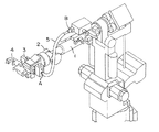
図1はハンドに非剛体付加物(ケーブル類)を持つロボットの一例を示す図である。 FIG. 1 is a diagram showing an example of a robot having a non-rigid attachment (cables) in a hand.
このロボットは6軸の多関節型スポット溶接ロボットであって、アーム1の先端に手首2を介してハンド3が取り付けられている。ハンド3にはスポット溶接ガン4が取り付けられている。また、ロボットには、溶接に必要な電力やその他の制御信号を送るためのケーブル類5が付加されている。ケーブル類5は非剛体物であり、その両端がハンド側固定点Aとアーム側固定点Bにおいてそれぞれハンド3とアーム1に固定されている。手首2は回転軸(第4軸)、旋回軸(第5軸)、回転軸(第6軸)の計3軸構成になっている。ケーブル類5はロボットの動作(特に手首2の3軸の動作)にともない2つの固定点A、B間の相対位置が変わるためその形状等が変化することになる。
This robot is a 6-axis articulated spot welding robot, and a
次に、図1に示したロボットにおけるケーブル類の状態をシミュレーションして、ケーブル類の状態を診断するための方法について説明する。 Next, a method for diagnosing the state of the cables by simulating the state of the cables in the robot shown in FIG. 1 will be described.
まず、ケーブル類の状態(形状)を表現するための要素として、ケーブル類の自転ねじれと公転ねじれについて説明する。 First, as an element for expressing the state (shape) of the cables, a description will be given of the rotation twist and the revolution twist of the cables.
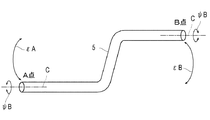
図2は、ケーブル類の自転ねじれと公転ねじれについて説明するための図面である。 FIG. 2 is a drawing for explaining rotation twist and revolution twist of cables.
図において、A点およびB点はケーブル類5の固定点である。ケーブル類5の自転ねじれは、ケーブル類5そのものの中心cが軸となって回転するねじれを言うものであり、ここではA点側の自転ねじれをψA、B点側の自転ねじれをψBと示す。一方、公転ねじれは、A点に対するB点の回転位置、およびB点に対するA点の回転位置を言い、ここではA点側の公転ねじれをεA、B点側の公転ねじれをεBと示す。
In the figure, points A and B are fixed points of the
そして、このケーブル類5全体のねじれは、これら自転ねじれおよび公転ねじれを使って表すことができる。すなわち、全ねじれω=ψA+ψB+εA+εBである。
And the torsion of this
このようなねじれは、大きければ大きいほどケーブル類の断線や破損につながる可能性が高い。しかも、本実施形態においては、このねじれを自転ねじれと公転ねじれに分けて表現し、これを加算することとしているため、ケーブル類のねじれを的確にしかも定量的に表すことができるのである。 The larger the twist, the higher the possibility that the cables will be disconnected or damaged. In addition, in this embodiment, the twist is expressed by dividing it into a rotation twist and a revolution twist, and these are added, so that the twist of the cables can be expressed accurately and quantitatively.
このようなねじれの計算は、具体的には、自転ψについては、固定点(A点、B点)がはじめの位置から自転した角度そのものである。 Specifically, the calculation of such a twist is the angle of the rotation of the fixed point (point A, point B) from the initial position for the rotation ψ.
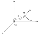
一方、公転ねじれについては、図3に示すように、固定点ごとに、3次元座標の原点をとり、3次元座標系における他点の位置を求めて、加算すればよい。すなわち、εAを求める場合には、A点を原点(0,0,0)としてB点の動作軌跡を3次元座標値(Xb,Yb,Zb)として求め、同様にεBは、B点を原点(0,0,0)としてA点の動作軌跡を3次元座標値(Xa,Ya,Za)として求めて、各動作軌跡の3次元座標値を加算する(Xa+Xb,Ya+Yb,Za+Zb)。 On the other hand, as shown in FIG. 3, the revolution torsion may be calculated by taking the origin of the three-dimensional coordinate for each fixed point and obtaining the position of another point in the three-dimensional coordinate system. That is, when obtaining εA, the point A is the origin (0, 0, 0) and the motion locus of the point B is obtained as a three-dimensional coordinate value (Xb, Yb, Zb). Similarly, εB is the point B as the origin. The motion trajectory at point A is determined as a three-dimensional coordinate value (Xa, Ya, Za) as (0, 0, 0), and the three-dimensional coordinate values of each motion trajectory are added (Xa + Xb, Ya + Yb, Za + Zb).
これにより、上記ωの後半部分であるεA+εBが得られる。得られる値は動作軌跡を時間間隔として区切れば時間間隔ごとの値が得られる。このようにして得られた公転ねじれの値は、後述するように、マハラノビスタグチ法における特徴量に用いるためのものであるので、公転ねじれを表すための値であればよく、座標値そのものを用いればよい。このため、公転ねじれの値はA点やB点を中心とした回転位置(または角度)にする変換する必要はない。なお、図3においては、A点を座標原点にとった図面を示したが、B点側の計算においては、図示しないが上記のとおりB点を座標原点として計算すればよい。 Thereby, εA + εB, which is the latter half of the ω, is obtained. The obtained value can be obtained for each time interval by dividing the motion trajectory into time intervals. As will be described later, the value of the revolution torsion obtained in this way is for use in the feature quantity in the Mahalanobis Taguchi method. Therefore, the value of the revolution torsion only needs to be a value for representing the revolution torsion, and the coordinate value itself is used. That's fine. For this reason, it is not necessary to convert the value of the revolution torsion to the rotational position (or angle) around the point A or the point B. Although FIG. 3 shows a drawing in which the point A is taken as the coordinate origin, in the calculation on the point B side, although not shown, it is sufficient to calculate the point B as the coordinate origin as described above.
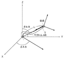
ケーブル類のたわみ(曲げ量)についても定義する。図4は、ケーブル類のたわみを説明するための3次元座標図である。 Also defines the deflection (bending amount) of cables. FIG. 4 is a three-dimensional coordinate diagram for explaining the deflection of the cables.
ここでは、A点をこの3次元座標系の原点にとり、A点からのケーブル類5の引き出されている方向をZ軸方向としている。そして、A点から見たB点の位置を、A点からB点へのベクトルABのX−Y平面へ投影したときのX軸とベクトルABの投影線とのなす角φAB、およびZ軸とベクトルABのなす角θABによって規定する。これにより、ケーブル類5のAB両端の相対的な位置が分かる。また、AB間の距離をL1とする。このL1は、ロボットの動きに合わせて変化する。さらに、ケーブル類5の長さをL2とする。ケーブル類5の長さL2はあらかじめ決まっているためロボットの動きによって変化する値ではない。
Here, the point A is taken as the origin of this three-dimensional coordinate system, and the direction in which the
そして、L1とL2との距離の差(L2−L1)が大きければ、ケーブルのたわみ量が大きくなる。なお、L2はシミュレーション対象となるロボットに付加されたケーブル類5ごとに固定量であるため、ロボットの動きによって変化するL1のみをケーブル類5のたわみに影響する値として定義してもよい。
If the distance difference (L2−L1) between L1 and L2 is large, the amount of cable deflection increases. Since L2 is a fixed amount for each
このように、ケーブル類のたわみ(曲げ量)についてケーブル類を固定する2点間の距離L1と、ベクトルABを表すための2つの角度φABおよびθABによって表現しているため、ケーブル類の曲げ量を的確にしかも定量的に表すことができるのである。 As described above, the deflection (bending amount) of the cables is expressed by the distance L1 between the two points for fixing the cables and the two angles φAB and θAB for representing the vector AB. Can be expressed accurately and quantitatively.
なお、この曲げ量を求める際に3次元座標系は任意でよく、必ずしもA点を座標原点にとる必要はない。また、2つのなす角は上記のようなφABとθABに限定されるものではなく、ベクトルABを表すための角度であれば、どのようなものであってもよい。 Note that the three-dimensional coordinate system may be arbitrary when obtaining the bending amount, and it is not always necessary to set the point A as the coordinate origin. Further, the angle formed by the two is not limited to φAB and θAB as described above, and may be any angle as long as it represents the vector AB.
このように、ケーブル類5の状態を、全ねじれωと、なす角φABおよびθAB、AB間距離L1により表現することで、ロボットの動作シミュレーションにおいては、シミュレーションされたロボット上のA点およびB点の位置変化から、ケーブル類5がどのようにねじれ、また曲がるかを定量的に表すことができる。
As described above, the state of the
なお、ここでは、曲げ量をあらわすための尺度の一つとしてベクトルABについてのなす角φABおよびθABを用いたが、これに代えて、上記同様にB点を原点とした3次元座標系でベクトルBAについて、ベクトルBAのX−Y平面へ投影したときのX軸とベクトルBAの投影線とのなす角φBA、およびZ軸とベクトルBAのなす角θBAによって規定してもよい。さらには、ベクトルABについてのなす角φABおよびθABと、ベクトルBAについてのなす角φBAおよびθBAのすべてを用いて表現するようにしてもよい。 Here, the angles φAB and θAB formed with respect to the vector AB are used as one of the measures for expressing the bending amount, but instead of this, the vector is expressed in a three-dimensional coordinate system with the point B as the origin as described above. BA may be defined by an angle φBA formed by the X axis and the projection line of the vector BA when projected onto the XY plane of the vector BA, and an angle θBA formed by the Z axis and the vector BA. Furthermore, the angles φAB and θAB formed with respect to the vector AB and the angles φBA and θBA formed with respect to the vector BA may all be used for the expression.
また、なす角は、上記のようなX−Y平面上におけるベクトルの投影線となす角やZ軸とのなす角に限らず、当然、他の平面や他の軸とのなす角であってもよい。すなわち、3次元座標系の1平面に投影されたベクトル(ベクトルABまたはベクトルBA)の投影線と1平面に含まれる一つの軸とのなす角、およびベクトルと3次元座標系の少なくとも1つの軸とのなす角、の2つの角度であればよい。 The angle formed is not limited to the angle formed with the projection line of the vector on the XY plane as described above or the angle formed with the Z axis, and of course, the angle formed with another plane or another axis. Also good. That is, an angle formed by a projection line of a vector (vector AB or vector BA) projected onto one plane of the three-dimensional coordinate system and one axis included in one plane, and at least one axis of the vector and the three-dimensional coordinate system It is sufficient that the angle is two angles.
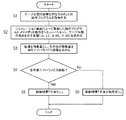
図5はケーブル類の状態診断方法の処理手順を示すフローチャートである。 FIG. 5 is a flowchart showing the processing procedure of the cable status diagnosis method.
まず、ケーブル類の診断を行うロボットの動作プログラムをシミュレーション装置に取り込む(S1)。なお、ここで動作プログラムとは、ロボットを動作させるためのティーチングプログラムであってもよいし、動作軌跡を示すものであってもよい。 First, a robot operation program for diagnosing cables is taken into the simulation apparatus (S1). Here, the operation program may be a teaching program for operating the robot, or may indicate an operation locus.
次に、ロボットの動作シミュレーション装置によって取得した動作プログラムによりロボット動作をシミュレーションする(S2)。このとき、上記のようにして定義したケーブル類のロボット動作にともなう形状変化を示すための各値が得られる。 Next, the robot motion is simulated by the motion program acquired by the robot motion simulation device (S2). At this time, each value for showing the shape change accompanying the robot operation | movement of the cables defined as mentioned above is obtained.
すなわち、ロボットの動作にともないロボット上のA点が自転した角度をロボットの動作シミュレーション結果から自転ねじれψAとして求め、同様に、B点の自転ねじれψB、A点側の公転ねじれεA、B点側の公転ねじれεBをそれぞれ求めて、これらを加算して全ねじれωを求める。また同様にロボット動作のシミュレーション結果から、ロボットのAB間の距離L1、A点からB点へのベクトルを表すためのなす角φABおよびθABを求める。求める各値は、シミュレーションの実行中、あらかじめ決められた時間間隔ごとの時系列で求める。 That is, the angle at which the A point on the robot rotates with the movement of the robot is obtained as the rotation twist ψA from the robot operation simulation result, and similarly, the B point rotation twist ψB, the A point side revolution twist εA, and the B point side Are obtained, and these are added together to obtain the total twist ω. Similarly, from the simulation result of the robot operation, the distance L1 between AB of the robot and the angles φAB and θAB formed to represent the vector from the point A to the point B are obtained. Each value to be obtained is obtained in a time series at predetermined time intervals during the execution of the simulation.
次に、シミュレーションによって得られた各値に、マハラノビスタグチ法(以下MT法と称する)で用いる特徴量として、さらにその他の特徴量を加えてマハラノビス距離を求める(S3、詳細後述)。 Next, the Mahalanobis distance is obtained by adding other feature quantities to the respective values obtained by the simulation as feature quantities used in the Mahalanobis Taguchi method (hereinafter referred to as the MT method) (S3, details will be described later).
次に、求めたマハラノビス距離をあらかじめ求められているマハラノビス距離による診断の基準値と比較する(S4)。このとき、S3で求めたマハラノビス距離が基準値以下であれば、不具合の発生する可能性はないものと判断する(S5)。一方、S3で求めたマハラノビス距離が基準値よりも大きければ不具合の発生する可能性が高いものと判断する(S6)。不具合の発生の可能性が高い場合には、その後、ロボットの動作(ティーチング)を見直したり、ケーブル類5長さを見直したりすることになる。
Next, the calculated Mahalanobis distance is compared with a reference value for diagnosis based on the previously determined Mahalanobis distance (S4). If the Mahalanobis distance calculated | required by S3 is below a reference value at this time, it will be judged that there is no possibility of a malfunction (S5). On the other hand, if the Mahalanobis distance obtained in S3 is larger than the reference value, it is determined that there is a high possibility that a malfunction will occur (S6). If there is a high possibility that a failure will occur, then the robot operation (teaching) will be reviewed and the length of the
MT法は、周知のとおり、複数の特徴量から正常空間の距離を求める必要がある。そこで、本実施の形態では、特徴量として、1:データ数、2:工場、3:ロボット型式、4:ケーブル類5長さ、5:ケーブル類5カバー方式(ケーブル類5カバーを用いているか否か、およびケーブル類5カバーを用いている場合にそのカバーの材質)、6:ケーブル類5結束方法(結束位置、結束数、結束に使用する部材(プラスチックバンド、樹脂被覆針金など)、結束ケーブル類5数など)、7:ケーブル類5種類(溶接用電源ケーブル類5、制御用配線ケーブル類5、サーボモータ用ケーブル類5、その他のケーブル類5の有無)、8:ホース類(エアー供給ホース、オイルホース、水供給ホースなどの有無)、9:AB間距離(ここでは前述したL1について、最大値、最小値、微分値をとっている)、10:ねじれω、11:X−Y平面上のなす角φAB、12:Z軸とベクトルABのなす角θABである。なお、ここでは、ねじれを自転ねじれと公転ねじれを加算した結果である全ねじれωを用いているが、これに代えて、個別の自転ねじれと公転ねじれ、すなわち、ψA、ψB、εA、εBをそれぞれ一つの特徴量として扱ってもよい。
As is well known, the MT method needs to obtain the distance of the normal space from a plurality of feature amounts. Therefore, in this embodiment, as the feature amount, 1: number of data, 2: factory, 3: robot type, 4:
これら特徴量の中で、上記特徴量1〜8は一つのロボットについてはそのロボットの動きによって変化しない値であり、これをここでは静的特徴量と称する。 Among these feature amounts, the above-described feature amounts 1 to 8 are values that do not change with the movement of one robot, and are referred to as static feature amounts herein.
一方、特徴量9〜12は、ロボットの動作にしたがって変化する値であり、これらを動的特徴量と称する。そして、動的特徴量である特徴量9〜12については、その時間変化(ロボットの動きの変化)を捕らえる特徴量とするために、あらかじめ決められ所定時間間隔ごとに、その時間間隔内における最小値、最大値、平均、および標準偏差を求めて、それぞれの区間ごとの値と、さらに全区間における最小値、最大値、平均、および標準偏差をもとめ、それらすべてを特徴量として用いている。 On the other hand, the feature amounts 9 to 12 are values that change according to the operation of the robot, and these are referred to as dynamic feature amounts. For the feature quantities 9 to 12 which are dynamic feature quantities, in order to obtain a feature quantity that captures the change over time (change in the movement of the robot), a minimum value within the time interval is determined at predetermined time intervals. Values, maximum values, averages, and standard deviations are obtained, and values for each section and minimum values, maximum values, averages, and standard deviations in all sections are obtained, and all of them are used as feature amounts.
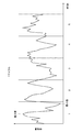
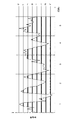
たとえば、図6に示すように、ロボットの1サイクルの動作を、一つの間隔の時間を1秒として5区間に分割した場合、それぞれの区画ごとに最小値、最大値、平均、および標準偏差をとり、さらに、全区画における最小値、最大値、平均、および標準偏差をとると、全特徴量数は、一つの特徴量において(分割数+1)×4となる。 For example, as shown in FIG. 6, when the operation of one cycle of the robot is divided into five sections with one interval time being 1 second, the minimum value, maximum value, average, and standard deviation are calculated for each section. Furthermore, if the minimum value, the maximum value, the average, and the standard deviation in all the sections are taken, the total number of feature amounts is (division number + 1) × 4 in one feature amount.
なお、上述した特徴量は、すべてが必ず必要となるものではなく、少なくともロボットの動作によってケーブル類5のねじれや曲がり方など、ケーブル類5の状態変化を示す特徴量9〜12があればよい。これは、たとえば、工場が一つしかなく、動作は異なるが同じ型式のロボットを用いている場合は、工場やロボット型式などの特徴量は変化しないためなくてもよい。逆に、さらに多くの特徴量を用いてもよいことはいうまでもない。
Note that the above-described feature amounts are not necessarily required, and at least feature amounts 9 to 12 that indicate a change in the state of the
MT法では、これらの特徴量を用いて正常空間の距離を求める。したがって、実際に稼動しており、ケーブル類5に不具合の発生していないロボットについて、その動作軌跡、またはプログラムを用いたシミュレーション結果から上記各特徴量を取得して、マハラノビス距離を算出する。なお、MT法の実行には、市販のソフトウェアを利用すればよい。MT法を実行するための市販ソフトとしては、たとえば、株式会社オーケン製MTS for windows Excel版などがある。
In the MT method, the distance of the normal space is obtained using these feature amounts. Therefore, the Mahalanobis distance is calculated by acquiring the above feature quantities from the motion trajectory or the simulation result using the program for the robot that is actually operating and in which the
そして、これによって算出されたマハラノビス距離の最大値が、上記ステップS4で用いる基準値となる。 The maximum value of the Mahalanobis distance calculated as a result is the reference value used in step S4.
これにより、これから動作させるロボットにおけるケーブル類のロボット動作にともなう不具合を容易に診断することができる。 Thereby, it is possible to easily diagnose a problem associated with the robot operation of the cables in the robot to be operated in the future.
特に、本実施の形態のように、MT法で用いる特徴量として、工場、ロボットの型式、などを加えることで、検査対象のロボットを据え付ける場所や、ロボットの型式の違いなどの影響をも加味したケーブル類の診断を行うことが可能となる。 In particular, as in this embodiment, adding the factory, robot model, etc. as feature quantities used in the MT method also takes into account the influence of the location of the robot to be inspected and the difference in robot model. This makes it possible to diagnose cables that have been damaged.
なお、以上説明した実施形態においては、動的特徴量を時間間隔ごとに分けて、時間間隔ごとに最大値、最小値、平均値、および標準偏差を特徴量として用いることにしたが、これに代えて、または追加して各区間および/または全体の、最大値、最小値、微分値、および積分値を用いてもよい。 In the embodiment described above, the dynamic feature amount is divided for each time interval, and the maximum value, the minimum value, the average value, and the standard deviation are used as the feature amount for each time interval. Instead of or in addition, the maximum value, the minimum value, the differential value, and the integral value of each section and / or the whole may be used.
微分値は、全区間を微小時間で微分した値を用いてもよいが、簡易的には、たとえば、図7に示すように、特徴量の時間変化の値を所定の値で区切った線(イ〜チ)を引き、時間変化の値がイ〜チの各線を横切った値を区間ごとに求めてその横切った回数を微分値とてもよい。一方、積分値は、イ〜チの各線の各区間における時間変化の内側の長さ(図で示した太線部分の長さ)を区間ごとに加算した値として求めることができる。 As the differential value, a value obtained by differentiating the entire section with a minute time may be used. For simplicity, for example, as shown in FIG. It is very good to differentiate the number of times that the value of time change crosses each line of i to h for each section. On the other hand, the integral value can be obtained as a value obtained by adding the inner length (the length of the thick line portion shown in the figure) of the time change in each section of each of the lines from 1 to 1 for each section.
このような簡易的な微分値および積分値を用いてもケーブル類のねじれや曲げの状態を時系列としてあらわすことができ、ロボットの動作にともなうケーブル類の断線や破損などの状態変化(不具合の発生)を、MT法を用いて診断することができる。 Even with these simple differential and integral values, the twisted or bent state of the cables can be represented as a time series, and state changes such as cable disconnection or breakage caused by robot operation (defects) Occurrence) can be diagnosed using the MT method.
本発明は、新たに設置するロボットに付加された非剛体物の不具合発生の可能性を検証できるほか、既存のロボットにおいても新たに動作軌跡をティーチングしなおす場合、また、既存のロボットにおいて、現状の見た目では、不具合が発生していないものでも、今後不具合の発生する可能性があるか否かを検証することもできる。 The present invention can verify the possibility of occurrence of defects of non-rigid objects added to newly installed robots. In addition, when re-teaching motion trajectories in existing robots, In this way, it is possible to verify whether or not there is a possibility that a failure will occur in the future even if no failure has occurred.
1…アーム、
2…手首、
3…ハンド、
4…スポット溶接ガン、
5…ケーブル類。
1 ... arm,
2 ... wrist,
3 ... hand,
4 ... Spot welding gun,
5: Cables.
Claims (9)
前記ロボットの動作にともなう前記ロボット上の前記第1固定点が自転した角度を前記非剛体物の第1の自転ねじれとして求める段階と、
前記ロボットの動作にともなう前記ロボット上の前記第2固定点が自転した角度を前記非剛体物の第2の自転ねじれとして求める段階と、
前記ロボットの動作にともなう前記第1固定点に対する前記第2固定点の位置変化を前記非剛体物の第1の公転ねじれとして求める段階と、
前記ロボットの動作にともなう前記第2固定点に対する前記第1固定点の位置変化を前記非剛体物の第2の公転ねじれとして求める段階と、
前記第1の自転ねじれ、前記第2の自転ねじれ、前記第1の公転ねじれ、および前記第2の公転ねじれを加算する段階と、を有し、
前記加算結果を前記非剛体物のねじれ量とすることを特徴とするロボット付加非剛体物のシミュレーション方法。 A robot-added non-rigid object simulation method for simulating the state of a non-rigid object whose both ends are fixed to a first fixed point and a second fixed point on a robot,
Obtaining an angle of rotation of the first fixed point on the robot as the robot moves as a first rotation twist of the non-rigid object;
Obtaining an angle of rotation of the second fixed point on the robot as the robot moves as a second rotation twist of the non-rigid object;
Obtaining a change in position of the second fixed point relative to the first fixed point with the movement of the robot as a first revolution torsion of the non-rigid object;
Obtaining a change in position of the first fixed point relative to the second fixed point with the movement of the robot as a second revolution twist of the non-rigid object;
Adding the first rotation twist, the second rotation twist, the first revolution twist, and the second revolution twist,
A simulation method of a robot-added non-rigid object, wherein the addition result is a twist amount of the non-rigid object.
前記第2の公転ねじれとして算出する段階は、前記第2固定点を座標原点に定めた3次元座標系上で前記第1固定点の位置を求めることを特徴とする請求項1記載のロボット付加非剛体物のシミュレーション方法。 The step of calculating as the first revolution torsion obtains the position of the second fixed point on a three-dimensional coordinate system in which the first fixed point is set as a coordinate origin,
2. The robot addition according to claim 1, wherein the step of calculating as the second revolution torsion obtains a position of the first fixed point on a three-dimensional coordinate system in which the second fixed point is set as a coordinate origin. Simulation method for non-rigid objects.
任意の3次元座標系において前記第1固定点から前記第2固定点までのベクトルを表す角度を求める段階と、を有し、
前記距離および前記角度により前記非剛体物の曲げ量を表現することを特徴とする請求項1記載のロボット付加非剛体物のシミュレーション方法。 And determining a distance between the first fixed point and the second fixed point;
Obtaining an angle representing a vector from the first fixed point to the second fixed point in an arbitrary three-dimensional coordinate system,
The robot-added non-rigid object simulation method according to claim 1, wherein a bending amount of the non-rigid object is expressed by the distance and the angle.
前記3次元座標系の1平面に投影された前記ベクトルの投影線と前記1平面に含まれる一つの軸とのなす角、および前記ベクトルと前記3次元座標系の少なくとも1つの軸とのなす角、の2つの角度であることを特徴とする請求項3記載のロボット付加非剛体物のシミュレーション方法。 An angle indicating a vector from the first fixed point to the second fixed point is:
An angle formed between a projection line of the vector projected onto one plane of the three-dimensional coordinate system and one axis included in the one plane, and an angle formed between the vector and at least one axis of the three-dimensional coordinate system. The method for simulating a robot-added non-rigid object according to claim 3, wherein the angle is two angles.
前記ロボットの動作にともなう前記ロボット上の前記第1固定点が自転した角度を前記非剛体物の第1の自転ねじれとして求める段階と、
前記ロボットの動作にともなう前記ロボット上の前記第2固定点が自転した角度を前記非剛体物の第2の自転ねじれとして求める段階と、
前記ロボットの動作にともなう前記第1固定点に対する前記第2固定点の位置変化を前記非剛体物の第1の公転ねじれとして求める段階と、
前記ロボットの動作にともなう前記第2固定点に対する前記第1固定点の位置変化を前記非剛体物の第2の公転ねじれとして求める段階と、
前記ロボットの動作にともなう前記第1固定点と前記第2固定点の間の距離を求める段階と、
任意の3次元座標系における前記ロボットの動作にともなう前記第1固定点から前記第2固定点までのベクトルを表す角度を求める段階と、
少なくとも前記第1の自転ねじれ、前記第2の自転ねじれ、前記第1の公転ねじれ、前記第2の公転ねじれ、前記距離、および前記角度をマハラノビスタグチ法における特徴量として用いてマハラノビス距離を求める段階と、
求めた前記マハラノビス距離があらかじめ求められているマハラノビスタグチ法における正常空間内であるか否かにより非剛体物の状態を診断する段階と、を有することを特徴とするロボット付加非剛体物の状態診断方法。 A method for diagnosing a state of a non-rigid object added to a robot for diagnosing a state of a non-rigid object having both ends fixed to a first fixed point and a second fixed point on the robot,
Obtaining an angle at which the first fixed point on the robot rotates along with the movement of the robot as a first rotation twist of the non-rigid object;
Obtaining an angle at which the second fixed point on the robot rotates along with the movement of the robot as a second rotation twist of the non-rigid object;
Obtaining a change in position of the second fixed point relative to the first fixed point with the movement of the robot as a first revolution torsion of the non-rigid object;
Obtaining a change in position of the first fixed point relative to the second fixed point with the movement of the robot as a second revolution torsion of the non-rigid object;
Obtaining a distance between the first fixed point and the second fixed point accompanying the movement of the robot;
Obtaining an angle representing a vector from the first fixed point to the second fixed point associated with the movement of the robot in an arbitrary three-dimensional coordinate system;
A step of obtaining a Mahalanobis distance using at least the first rotation twist, the second rotation twist, the first revolution twist, the second revolution twist, the distance, and the angle as a characteristic amount in the Mahalanobis Taguchi method. When,
Diagnosing the state of a non-rigid object based on whether or not the obtained Mahalanobis distance is in a normal space in the Mahalanobis Taguchi method, which has been obtained in advance, Method.
前記第2の公転ねじれとして算出する段階は、前記第2固定点を座標原点に定めた3次元座標系上で前記第1固定点の位置を求めることを特徴とする請求項5記載のロボット付加非剛体物の状態診断方法。 The step of calculating as the first revolution torsion obtains the position of the second fixed point on a three-dimensional coordinate system in which the first fixed point is set as a coordinate origin,
6. The robot addition according to claim 5, wherein the step of calculating as the second revolution torsion obtains a position of the first fixed point on a three-dimensional coordinate system in which the second fixed point is set as a coordinate origin. Non-rigid object state diagnosis method.
前記3次元座標系の1平面に投影された前記ベクトルの投影線と前記1平面に含まれる一つの軸とのなす角、および前記ベクトルと前記3次元座標系の少なくとも1つの軸とのなす角、の2つの角度であることを特徴とする請求項5記載のロボット付加非剛体物の状態診断方法。 An angle indicating a vector from the first fixed point to the second fixed point is:
An angle formed between a projection line of the vector projected onto one plane of the three-dimensional coordinate system and one axis included in the one plane, and an angle formed between the vector and at least one axis of the three-dimensional coordinate system. 6. The method for diagnosing a state of a robot-added non-rigid object according to claim 5, wherein the angle is two angles.
Priority Applications (1)
| Application Number | Priority Date | Filing Date | Title |
|---|---|---|---|
| JP2004108696A JP2005293331A (en) | 2004-04-01 | 2004-04-01 | Method for simulating robot-added non-rigid object and method for diagnosing state of robot-added non-rigid object |
Applications Claiming Priority (1)
| Application Number | Priority Date | Filing Date | Title |
|---|---|---|---|
| JP2004108696A JP2005293331A (en) | 2004-04-01 | 2004-04-01 | Method for simulating robot-added non-rigid object and method for diagnosing state of robot-added non-rigid object |
Publications (1)
| Publication Number | Publication Date |
|---|---|
| JP2005293331A true JP2005293331A (en) | 2005-10-20 |
Family
ID=35326180
Family Applications (1)
| Application Number | Title | Priority Date | Filing Date |
|---|---|---|---|
| JP2004108696A Pending JP2005293331A (en) | 2004-04-01 | 2004-04-01 | Method for simulating robot-added non-rigid object and method for diagnosing state of robot-added non-rigid object |
Country Status (1)
| Country | Link |
|---|---|
| JP (1) | JP2005293331A (en) |
Cited By (7)
| Publication number | Priority date | Publication date | Assignee | Title |
|---|---|---|---|---|
| JP2007148894A (en) * | 2005-11-29 | 2007-06-14 | Fuji Electric Retail Systems Co Ltd | Crime prevention apparatus, crime prevention system, and crime prevention program |
| JP2009252183A (en) * | 2008-04-10 | 2009-10-29 | Sumitomo Electric Ind Ltd | Method for predicting shield line behavior, system for predicting shield line behavior, method for manufacturing shield cable, and device with shield cable |
| CN102909725A (en) * | 2011-08-04 | 2013-02-06 | 发那科株式会社 | Robot simulation device for simulating behavior of umbilical member |
| JP2015085437A (en) * | 2013-10-30 | 2015-05-07 | 富士通株式会社 | Determination device, determination method, and determination program |
| US10216874B2 (en) | 2014-11-06 | 2019-02-26 | Fanuc Corporation | Robot simulation device |
| WO2022137581A1 (en) * | 2020-12-23 | 2022-06-30 | オムロン株式会社 | Simulation device and simulation program |
| JP2023037248A (en) * | 2021-09-03 | 2023-03-15 | オムロン株式会社 | Simulation system, simulation method, and program of simulation |
Citations (3)
| Publication number | Priority date | Publication date | Assignee | Title |
|---|---|---|---|---|
| JPH05216920A (en) * | 1992-02-03 | 1993-08-27 | Yamaha Motor Co Ltd | Stable shape analysis device for linear members |
| JPH10275007A (en) * | 1997-03-31 | 1998-10-13 | Nissan Motor Co Ltd | Robot movement simulation method |
| JP2003141306A (en) * | 2001-10-30 | 2003-05-16 | Ohken:Kk | Evaluation system |
-
2004
- 2004-04-01 JP JP2004108696A patent/JP2005293331A/en active Pending
Patent Citations (3)
| Publication number | Priority date | Publication date | Assignee | Title |
|---|---|---|---|---|
| JPH05216920A (en) * | 1992-02-03 | 1993-08-27 | Yamaha Motor Co Ltd | Stable shape analysis device for linear members |
| JPH10275007A (en) * | 1997-03-31 | 1998-10-13 | Nissan Motor Co Ltd | Robot movement simulation method |
| JP2003141306A (en) * | 2001-10-30 | 2003-05-16 | Ohken:Kk | Evaluation system |
Cited By (13)
| Publication number | Priority date | Publication date | Assignee | Title |
|---|---|---|---|---|
| JP2007148894A (en) * | 2005-11-29 | 2007-06-14 | Fuji Electric Retail Systems Co Ltd | Crime prevention apparatus, crime prevention system, and crime prevention program |
| JP2009252183A (en) * | 2008-04-10 | 2009-10-29 | Sumitomo Electric Ind Ltd | Method for predicting shield line behavior, system for predicting shield line behavior, method for manufacturing shield cable, and device with shield cable |
| CN102909725A (en) * | 2011-08-04 | 2013-02-06 | 发那科株式会社 | Robot simulation device for simulating behavior of umbilical member |
| JP2013035083A (en) * | 2011-08-04 | 2013-02-21 | Fanuc Ltd | Robot simulation device for simulating behavior of filament body |
| CN102909725B (en) * | 2011-08-04 | 2013-11-27 | 发那科株式会社 | Robot simulation device for simulating behavior of umbilical member |
| JP2015085437A (en) * | 2013-10-30 | 2015-05-07 | 富士通株式会社 | Determination device, determination method, and determination program |
| US10216874B2 (en) | 2014-11-06 | 2019-02-26 | Fanuc Corporation | Robot simulation device |
| DE102015013988B4 (en) | 2014-11-06 | 2019-10-24 | Fanuc Corporation | Robot simulation device |
| WO2022137581A1 (en) * | 2020-12-23 | 2022-06-30 | オムロン株式会社 | Simulation device and simulation program |
| JP2022099420A (en) * | 2020-12-23 | 2022-07-05 | オムロン株式会社 | Simulation device and simulation program |
| JP7556283B2 (en) | 2020-12-23 | 2024-09-26 | オムロン株式会社 | Simulation device and simulation program |
| JP2023037248A (en) * | 2021-09-03 | 2023-03-15 | オムロン株式会社 | Simulation system, simulation method, and program of simulation |
| JP7694271B2 (en) | 2021-09-03 | 2025-06-18 | オムロン株式会社 | Simulation system, simulation method, and simulation program |
Similar Documents
| Publication | Publication Date | Title |
|---|---|---|
| US20070073444A1 (en) | Offline teaching apparatus for robot | |
| US11398003B2 (en) | Machine learning apparatus, robot system, and machine learning method of learning state of cable | |
| JP2021160031A (en) | Failure prediction method and failure prediction device | |
| JP7556283B2 (en) | Simulation device and simulation program | |
| JP2005293331A (en) | Method for simulating robot-added non-rigid object and method for diagnosing state of robot-added non-rigid object | |
| Süberkrüb et al. | Feel the tension: Manipulation of deformable linear objects in environments with fixtures using force information | |
| JP2016087750A (en) | Robot simulation device | |
| Jaensch et al. | Virtual commissioning simulation as reinforcement learning environment for robot cable handling | |
| JP2019010706A (en) | Torch cable interference evaluation information output device, evaluation information output method and program for weld robot | |
| JP2008100315A (en) | Control simulation system | |
| JP2004151976A (en) | Simulation equipment | |
| CN110053045A (en) | Workpiece surface contour line acquisition methods, interference detection method and relevant apparatus | |
| CN113664874A (en) | Interference detection method for multiple arms of mobile robot | |
| JP4928528B2 (en) | Wire harness moving path analysis system | |
| JP7832919B2 (en) | Control support system, control support method, and control support program | |
| Kressin | Path optimization for multi-robot station minimizing dresspack wear | |
| JP7232704B2 (en) | ROBOT PROGRAM EVALUATION DEVICE, ROBOT PROGRAM EVALUATION METHOD AND ROBOT PROGRAM EVALUATION PROGRAM | |
| Mitrović et al. | System for simulation and supervision of robotic cells | |
| CN112955832B (en) | Computer-implemented method for determining sensor location during simulation of automated systems | |
| JP4746058B2 (en) | Wire harness movable path display system | |
| JP7821435B2 (en) | Robot motion planning support system, robot motion planning support method, and computer program | |
| JP2022128114A (en) | Maintenance support system | |
| Fattah et al. | Anomaly detection for industrial robot prognostics and health management | |
| Gábor et al. | Technológiai áttekintés, csatlakozó házak feldolgozásához szükséges cella tervezés: Technological overview, design of a machine station for connector processing | |
| Mendes et al. | Simulation Approach for Soft Manipulators in Gazebo using Kinematic Model |
Legal Events
| Date | Code | Title | Description |
|---|---|---|---|
| A621 | Written request for application examination |
Free format text: JAPANESE INTERMEDIATE CODE: A621 Effective date: 20070402 |
|
| A977 | Report on retrieval |
Free format text: JAPANESE INTERMEDIATE CODE: A971007 Effective date: 20090622 |
|
| A131 | Notification of reasons for refusal |
Free format text: JAPANESE INTERMEDIATE CODE: A131 Effective date: 20090630 |
|
| A02 | Decision of refusal |
Free format text: JAPANESE INTERMEDIATE CODE: A02 Effective date: 20091027 |