JP2005293100A - Assembly part ordering method, assembly part ordering program, and assembly part ordering mediation program - Google Patents
Assembly part ordering method, assembly part ordering program, and assembly part ordering mediation program Download PDFInfo
- Publication number
- JP2005293100A JP2005293100A JP2004105798A JP2004105798A JP2005293100A JP 2005293100 A JP2005293100 A JP 2005293100A JP 2004105798 A JP2004105798 A JP 2004105798A JP 2004105798 A JP2004105798 A JP 2004105798A JP 2005293100 A JP2005293100 A JP 2005293100A
- Authority
- JP
- Japan
- Prior art keywords
- design drawing
- data
- identifier
- component
- frame structure
- Prior art date
- Legal status (The legal status is an assumption and is not a legal conclusion. Google has not performed a legal analysis and makes no representation as to the accuracy of the status listed.)
- Granted
Links
Images



Landscapes
- Management, Administration, Business Operations System, And Electronic Commerce (AREA)
Abstract
【課題】 所望の構造を組み立てるために必要な部品について、提供された各部品の配置を効率的に特定するための組立部品発注方法、組立部品発注プログラム及び組立部品発注仲介プログラムを提供する。
【解決手段】 利用者端末30は、装置のフレーム構造を構成する各部品を特定し、各部品に対応するカタログ記号毎にパーツ番号を付与する。そして、そのフレーム構造の設計図面において、各部品に関連付けてパーツ番号を表示する設計図面を生成し、その設計図面を復元可能なデータを生成する。そして、各部品の種類毎のパーツ番号、カタログ記号、及び数量に関するデータと、設計図面を復元可能なデータとを管理コンピュータ21に送信する。管理コンピュータ21は、メーカ端末40に、設計図面を出力させるとともに、パーツ番号、カタログ記号、及び数量を含むラベルを出力させる。
【選択図】 図2PROBLEM TO BE SOLVED: To provide an assembly part ordering method, an assembly part ordering program, and an assembly part ordering mediation program for efficiently specifying the arrangement of each provided part for parts necessary for assembling a desired structure.
A user terminal 30 identifies each part constituting the frame structure of the apparatus and assigns a part number to each catalog symbol corresponding to each part. Then, in the design drawing of the frame structure, a design drawing that displays a part number in association with each part is generated, and data that can restore the design drawing is generated. Then, data on the part number, catalog symbol, and quantity for each type of part and data that can restore the design drawing are transmitted to the management computer 21. The management computer 21 causes the maker terminal 40 to output a design drawing and a label including a part number, a catalog symbol, and a quantity.
[Selection] Figure 2
Description
本発明は、所望の構造を組み立てるために必要な部品の発注を行うための組立部品発注方法、組立部品発注プログラム及び組立部品発注仲介プログラムに関する。 The present invention relates to an assembly part ordering method, an assembly part ordering program, and an assembly part ordering mediation program for ordering parts necessary for assembling a desired structure.
フレーム部材を用いてフレーム構造を組み立てる場合、所望のフレーム構造を組み立てるためには、そのフレーム構造に対応する長さのフレーム部材を用意する必要がある。このため、フレーム構造を組み立てる利用者は、必要な長さのフレーム部材を入手する必要がある。この場合、利用者側でフレーム構造の設計を行い、フレーム部材の長さを特定してメーカに注文することが一般的である。この注文に応じて、メーカ側では、用意されているフレーム部材を指定された長さに切断し、加工後のフレーム部材を利用者に提供する。これにより、利用者は、所望のフレーム構造を組み立てるために必要な長さのフレーム部材を入手できるため、入手したフレーム部材を用いて、所望のフレーム構造を組み立てることができる。 When assembling a frame structure using a frame member, in order to assemble a desired frame structure, it is necessary to prepare a frame member having a length corresponding to the frame structure. For this reason, the user who assembles the frame structure needs to obtain a frame member having a necessary length. In this case, it is common to design the frame structure on the user side, specify the length of the frame member, and place an order with the manufacturer. In response to this order, the manufacturer cuts the prepared frame member to a specified length and provides the user with the processed frame member. Thereby, since the user can obtain the frame member having a length necessary for assembling the desired frame structure, the user can assemble the desired frame structure using the obtained frame member.
一方、フレーム部材の注文については、フレーム構造の組立に必要なフレーム部材のセットをフレームキットとして注文するシステムが開示されている(例えば、特許文献1参照。)。このシステムでは、加工されたフレーム部材のセットとともに、各フレーム部材についてそれぞれ寸法を記載した組立図を提供する。このため、利用者は、その組み立て図に基づいて、フレーム構造の組立を行うことができる。
しかし、組立図に寸法が記載されていたとしても、組立図に記載されているフレーム部材と実際のフレーム部材と照合する場合に、組立図に記載された寸法を用いるのは、煩雑である。特に、立体形状のフレーム構造を組み立てる場合、各面についての設計図が必要となるため、使用するフレーム部材について、より分かり易い表示がされることが望ましい。さらに、例えば、直方体のフレーム構造のように、同じ長さのフレーム部材を複数使用する場合が多くあるが、このような場合に、フレーム部材の配置を、より特定しやすくすることができることが望ましい。 However, even if the dimensions are described in the assembly drawing, it is complicated to use the dimensions described in the assembly drawing when collating the frame member described in the assembly drawing with the actual frame member. In particular, when assembling a three-dimensional frame structure, a design drawing for each surface is required. Therefore, it is desirable that the frame members to be used be displayed more easily. Furthermore, for example, there are many cases where a plurality of frame members having the same length are used, such as a rectangular parallelepiped frame structure. In such a case, it is desirable that the arrangement of the frame members can be more easily specified. .
本発明は、上記問題点を解決するためになされたものであり、その目的は、所望の構造を組み立てるために必要な部品について、提供された各部品の配置を効率的に特定するための組立部品発注方法、組立部品発注プログラム及び組立部品発注仲介プログラムを提供することにある。 The present invention has been made to solve the above-described problems, and an object thereof is assembling for efficiently specifying the arrangement of each provided component with respect to components necessary for assembling a desired structure. To provide a part ordering method, an assembly part ordering program, and an assembly part ordering mediation program.
上記問題点を解決するために、請求項1に記載の発明は、利用者端末と、部品提供者端末と、管理コンピュータとを用いて、組立部品の発注を行う方法であって、前記利用者端末が、フレーム構造を特定する第1の段階と、前記フレーム構造を構成する各部品を特定し、特定された各部品の種類毎に、それぞれ特定のパーツ識別子を付与する第2の段階と、前記フレーム構造の設計図面を生成し、その設計図面に前記各部品に関連付けて前記パーツ識別子を表示するための設計図面データを生成する第3の段階と、前記各部品の種類毎の前記パーツ識別子、部品識別子、及び数量に関する情報を含む注文情報を生成する第4の段階と、前記管理コンピュータが、前記注文情報を受け付けて、この注文情報に基づ
いて、前記パーツ識別子、部品識別子、及び数量に関するデータとを前記部品提供者端末に送信する第5の段階と、前記部品提供者端末が、前記パーツ識別子と前記部品識別子と前記数量とを関連付けて出力し、前記パーツ識別子毎に前記パーツ識別子を含むラベルを印刷するための処理を行う第6の段階とを備えたことを要旨とする。
In order to solve the above problems, the invention described in
請求項2に記載の発明は、請求項1に記載の組立部品発注方法において、前記利用者端末が、前記設計図面データに基づいて、前記設計図面を復元可能な情報を生成する段階と、前記管理コンピュータが、前記設計図面を復元可能な情報を受け付けて、前記設計図面を復元可能な情報に基づいて、前記設計図面を復元し、前記設計図面を表示するための設計図面表示データを生成し、前記設計図面表示データを前記部品提供者端末に送信する段階と、前記部品提供者端末が、前記設計図面表示データに基づいて前記設計図面を出力する段階とをさらに備えたことを要旨とする。
The invention according to
請求項3に記載の発明は、請求項1又は2に記載の組立部品発注方法において、前記部品は、前記部品の原型の加工形状を含み、前記部品が前記部品の原型の加工形状である場合は、前記部品識別子は、前記部品の原型を特定する原型識別子と前記加工形状の特定情報とを含み、前記第2の段階は、前記フレーム構造の構成面の属性情報を設定する段階と、前記構成面の属性情報に基づいて部品を特定する段階と、前記部品毎に、前記パーツ識別子を付与する段階とを備え、構成面の属性情報に基づいて部品を特定する段階は、前記部品が前記原型の加工形状である場合、前記部品を前記原型と前記加工形状とにより特定することを要旨とする。 According to a third aspect of the present invention, in the assembly part ordering method according to the first or second aspect, the part includes an original processing shape of the part, and the part has an original processing shape of the part. The component identifier includes a prototype identifier that identifies a prototype of the component and identification information of the machining shape, and the second step includes setting attribute information of a configuration surface of the frame structure; Identifying the part based on the attribute information of the component surface, and assigning the part identifier for each component, and identifying the part based on the attribute information of the component surface, In the case of an original processing shape, the gist is to specify the component by the original shape and the processing shape.
請求項4に記載の発明は、請求項1〜3のいずれか1つに記載の組立部品発注方法において、前記第1の段階は、基本形状を特定する段階と、前記基本形状の構成面を特定して、その構成面の分割位置を特定する分割位置特定段階とを備え、前記基本形状において、前記特定された構成面を前記特定された分割位置で分割したフレーム構造を特定することを要旨とする。 According to a fourth aspect of the present invention, in the assembly part ordering method according to any one of the first to third aspects, the first step includes a step of specifying a basic shape and a component surface of the basic shape. Specifying a frame structure obtained by dividing the specified component surface at the specified division position in the basic shape, and including a division position specifying step of specifying a division position of the component surface And
請求項5に記載の発明は、請求項4に記載の組立部品発注方法において、前記分割位置特定段階は、前記特定した構成面の基準となる頂点を特定し、前記頂点を含む端面を特定し、その端面からの距離を特定することにより、分割位置を特定することを要旨とする。 According to a fifth aspect of the present invention, in the assembly part ordering method according to the fourth aspect, the division position specifying step specifies a vertex that serves as a reference for the specified component surface, and specifies an end surface that includes the vertex. The gist is to specify the division position by specifying the distance from the end face.
請求項6に記載の発明は、利用者端末と、部品提供者端末と、管理コンピュータとを用いて、利用者が前記利用者端末により組立部品の発注を行うための組立部品発注プログラムであって、前記利用者端末を、フレーム構造を特定する第1の手段と、前記フレーム構造を構成する各部品を特定し、特定された各部品の種類毎に、それぞれ特定のパーツ識別子を付与する第2の手段と、前記フレーム構造の設計図面を生成し、その設計図面に前記各部品に関連付けて前記パーツ識別子を表示するための設計図面データを生成する第3の手段と、前記パーツ識別子毎に前記パーツ識別子を含むラベルを前記部品提供者端末に印刷させ、前記パーツ識別子と部品識別子と数量とを関連付けて前記部品提供者端末に出力させるための前記パーツ識別子、部品識別子及び数量に関する情報を前記管理コンピュータに入力するための注文情報を出力する第4の手段として機能させることを要旨とする。 The invention according to claim 6 is an assembly parts ordering program for a user to place an order for assembly parts using the user terminal, using a user terminal, a parts provider terminal, and a management computer. The user terminal has a first means for specifying a frame structure, and specifies each part constituting the frame structure, and assigns a specific part identifier to each type of each specified part. Means for generating a design drawing of the frame structure, generating design drawing data for displaying the part identifier in association with each part on the design drawing, and for each part identifier The part identifier for causing a label including a part identifier to be printed on the part provider terminal and for causing the part provider terminal to output the part identifier, the part identifier, and the quantity in association with each other. And summarized in that to function as a fourth means for outputting order information for entering information about the part identifier and quantity to the management computer.
請求項7に記載の発明は、請求項6に記載の組立部品発注プログラムにおいて、前記利用者端末を、前記設計図面データに基づいて、前記設計図面を復元可能な情報を生成する手段と、前記設計図面を前記部品提供者端末に出力させるための前記設計図面を復元可能な情報を前記管理コンピュータに入力するための注文情報を出力する手段として機能させることを要旨とする。 The invention according to claim 7 is the assembly part ordering program according to claim 6, wherein the user terminal generates, based on the design drawing data, information capable of restoring the design drawing; The gist is to function as means for outputting order information for inputting information capable of restoring the design drawing for causing the parts provider terminal to output the design drawing to the management computer.
請求項8に記載の発明は、請求項6又は7に記載の組立部品発注プログラムにおいて、
前記部品は、前記部品の原型の加工形状を含み、前記部品が前記部品の原型の加工形状である場合は、前記部品識別子は、前記部品の原型を特定する原型識別子と前記加工形状の特定情報とを含み、前記第2の手段を、前記フレーム構造の構成面の属性情報を設定する手段と、前記構成面の属性情報に基づいて部品を特定する手段と、前記部品毎に、前記パーツ識別子を付与する手段として機能させ、構成面の属性情報に基づいて部品を特定する手段は、前記部品が前記原型の加工形状である場合、前記部品を前記原型と前記加工形状とにより特定することを要旨とする。
The invention according to
The part includes a processing shape of a prototype of the part, and when the component is a processing shape of the prototype of the part, the part identifier includes a prototype identifier for specifying the prototype of the part and specification information of the processing shape And the second means includes means for setting attribute information of the structural surface of the frame structure, means for specifying a part based on the attribute information of the structural surface, and for each part, the part identifier The means for specifying the part based on the attribute information of the configuration surface is to specify the part by the prototype and the machining shape when the part is the original machining shape. The gist.
請求項9に記載の発明は、請求項6〜8のいずれか1つに記載の組立部品発注プログラムにおいて、前記第1の手段を、基本形状を特定する手段と、前記基本形状の構成面を特定して、その構成面の分割位置を特定する分割位置特定手段として機能させ、前記基本形状において、前記特定された構成面を前記特定された分割位置で分割したフレーム構造を特定することを要旨とする。 The invention according to claim 9 is the assembly part ordering program according to any one of claims 6 to 8, wherein the first means includes means for specifying a basic shape, and a component surface of the basic shape. Identifying and functioning as a dividing position specifying means for specifying a dividing position of the constituent surface, and specifying a frame structure obtained by dividing the specified constituent surface at the specified dividing position in the basic shape And
請求項10に記載の発明は、請求項9に記載の組立部品発注プログラムにおいて、前記分割位置特定手段を、前記特定した構成面の基準となる頂点を特定し、前記頂点を含む端面を特定し、その端面からの距離を特定することにより、分割位置を特定する手段として機能させることを要旨とする。 According to a tenth aspect of the present invention, in the assembly part ordering program according to the ninth aspect, the division position specifying means specifies a vertex serving as a reference for the specified component surface, and specifies an end surface including the vertex. The gist is to specify the distance from the end face so as to function as means for specifying the division position.
請求項11に記載の発明は、利用者端末と、部品提供者端末と、管理コンピュータを用いて、前記管理コンピュータが、利用者から部品提供者への組立部品の発注を仲介するためのプログラムであって、前記管理コンピュータを、前記利用者端末において作成された、フレーム構造を構成する各部品の種類毎のパーツ識別子、部品識別子、及び数量に関する情報を含む注文情報を受け付ける手段と、前記利用者端末において作成された、前記パーツ識別子が前記各部品に関連付けられて表示された前記フレーム構造の設計図面を復元可能な情報を受け付ける手段と、前記設計図面を復元可能な情報に基づいて、前記設計図面を復元し、前記設計図面を表示するための設計図面表示データを生成する手段と、前記設計図面表示データを前記部品提供者端末に送信する手段と、前記部品提供者端末に、前記パーツ識別子と部品識別子と数量とを関連付けて出力させるとともに、前記パーツ識別子を含むラベルを出力させるための前記パーツ識別子、部品識別子、及び数量に関するデータを送信する手段として機能させることを要旨とする。 The invention according to claim 11 is a program for using the user terminal, the parts provider terminal, and the management computer so that the management computer mediates the order of assembly parts from the user to the parts provider. And means for receiving order information including information relating to a part identifier, a part identifier, and a quantity for each type of each part constituting the frame structure created in the user terminal; Means for receiving information that can be used to restore the design drawing of the frame structure in which the part identifier is displayed in association with each of the parts, and the design based on the information that can restore the design drawing Means for restoring the drawing and generating design drawing display data for displaying the design drawing; and Means for transmitting to a provider terminal; and causing the component provider terminal to output the part identifier, the component identifier, and the quantity in association with each other, and to output a label including the part identifier, the component identifier, The gist is to function as a means for transmitting data relating to the quantity.
(作用)
請求項1又は6に記載の発明によれば、利用者は、利用者端末を用いて、装置の設計を容易に行うことができるとともに、その装置を組み立てるために必要な部品を容易に特定して、利用者端末により生成された発注情報により、特定された部品を発注することができる。
(Function)
According to the invention described in
一方、部品提供者は、パーツ識別子と部品識別子と数量とが関連付けられて出力されることで、利用者に提供する部品を効率的に用意できる。
さらに、部品提供者が、パーツ識別子毎のラベルを、そのパーツ識別子に対応する部品に添付することで、利用者は、そのラベルのパーツ識別子と、設計図面のパーツ識別子と照合することにより、組み立てるフレーム構造における部品の配置を容易に特定できる。
On the other hand, the parts provider can efficiently prepare parts to be provided to the user by outputting the part identifier, the part identifier, and the quantity in association with each other.
Furthermore, the part provider attaches a label for each part identifier to the part corresponding to the part identifier, and the user assembles by collating the part identifier of the label with the part identifier of the design drawing. The arrangement of parts in the frame structure can be easily specified.
請求項2又は7に記載の発明によれば、部品提供者は、復元された設計図面と、出力されたパーツ識別子、前記部品識別子、前記数量とを用いて、利用者に提供する部品を、より効率的に用意できる。
According to the invention of
請求項3又は8に記載の発明によれば、利用者は、構成面の属性情報を設定することにより、容易に、使用する部品を特定するための操作を行うことができる。さらに、部品が
、その部品の原型を加工した加工形状である場合には、部品は、原型と加工形状とにより特定され、その原型と加工形状毎にパーツ識別子が付与されるため、利用者は、パーツ識別子を用いて加工形状毎に部品を特定することができる。また、部品の原型と加工形状とが特定され、その加工形状毎に数量が特定されるため、部品提供者は、これに基づいて、効率的に部品を加工して提供することができる。
According to the third or eighth aspect of the invention, the user can easily perform an operation for specifying a part to be used by setting the attribute information of the configuration surface. Furthermore, when the part has a machining shape obtained by machining the prototype of the part, the part is specified by the prototype and the machining shape, and a part identifier is assigned to each prototype and machining shape. A part can be specified for each machining shape using the part identifier. Moreover, since the original part and the processing shape of the part are specified and the quantity is specified for each processing shape, the part provider can efficiently process and provide the part based on this.
請求項4又は9に記載の発明によれば、利用者端末は、いずれかの構成面が分割されているフレーム構造を組み立てる場合に、容易に、フレーム構造を特定することができる。そして、そのフレーム構造を組み立てることに必要な部品を特定できる。
According to the invention described in
請求項5又は10に記載の発明によれば、利用者は、分割する構成面について、その構成面の基準となる頂点を含む端面からの距離を特定することにより、容易に構成面の分割位置を特定することができる。 According to the invention described in claim 5 or 10, the user can easily divide the constituent surface by specifying the distance from the end surface including the vertex that is the reference of the constituent surface of the constituent surface to be divided. Can be specified.
請求項11に記載の発明によれば、管理コンピュータは、利用者が利用者端末を用いて設計したフレーム構造の組立に必要な部品の発注情報を受け付けて、設計図面を復元して、部品提供者に提供できる。また、部品提供者側で、パーツ識別子と部品識別子と数量とを関連付けて出力させ、パーツ識別子を含むラベルを印刷させるための情報を、利用者端末を用いて生成された発注情報に基づいて、部品提供者端末に送信できる。これにより、管理コンピュータは、利用者から部品提供者への装置のフレームを組み立てるために必要な部品の発注を、効率的に仲介できる。従って、利用者は、効率的に、装置のフレームを組み立てるために必要な部品の発注を行うことができる。また、部品提供者は、管理コンピュータから提供される情報に基づいて出力される設計図面と、パーツ識別子と部品識別子と数量とが関連付けられた情報と、印刷されるラベルを用いて、効率的に部品を利用者に提供できる。さらに、部品提供者側で出力されたラベルと、パーツ識別子が部品に関連付けられて表示された設計図面とを用いることで、組み立てるフレーム構造における部品の配置を容易に特定できる。 According to the invention described in claim 11, the management computer receives part ordering information necessary for assembling the frame structure designed by the user using the user terminal, restores the design drawing, and provides the parts Can be provided. Also, on the part provider side, the part identifier, the part identifier, and the quantity are output in association with each other, and the information for printing the label including the part identifier is based on the ordering information generated using the user terminal, Can be sent to the parts provider terminal. Thereby, the management computer can efficiently mediate the ordering of the parts necessary for assembling the frame of the apparatus from the user to the parts provider. Therefore, the user can efficiently order parts necessary for assembling the frame of the apparatus. Further, the component provider efficiently uses the design drawing output based on the information provided from the management computer, the information in which the part identifier, the component identifier, and the quantity are associated with each other, and the printed label. Parts can be provided to users. Furthermore, by using the label output on the part provider side and the design drawing in which the part identifier is displayed in association with the part, the arrangement of the parts in the frame structure to be assembled can be easily specified.
本発明によれば、所望の構造を組み立てるために必要な部品について、提供された各部品の配置を効率的に特定できる。 ADVANTAGE OF THE INVENTION According to this invention, arrangement | positioning of each provided component can be identified efficiently about the components required in order to assemble a desired structure.
以下、本発明を具体化した一実施形態を図1〜図12に従って説明する。本実施形態では、立体形状を構成するフレームを組み立てるためのパーツの発注を行う組立部品発注方法、組立部品発注プログラム及び組立部品発注仲介プログラムとして説明する。 Hereinafter, an embodiment embodying the present invention will be described with reference to FIGS. The present embodiment will be described as an assembly part ordering method, an assembly part ordering program, and an assembly part ordering mediation program for ordering parts for assembling a frame constituting a three-dimensional shape.
まず、図1を用いて、組立部品発注時の全体的な業務フローを説明する。本実施形態では、まず、販売会社は、利用者に対して、フレーム構造を設計し必要なパーツを発注するための組立部品発注プログラムを提供する。利用者は、まず、この組立部品発注プログラムにより、フレーム構造の設計を行う(W1)。そして、利用者は、必要なフレーム部材等のパーツを特定し、設計図を復元可能なデータと各パーツの種類や数量に関するデータとを含む注文データにより、フレーム構造の組立に必要なパーツを販売会社に発注する(W2)。 First, with reference to FIG. 1, the overall business flow when ordering assembly parts will be described. In this embodiment, first, the sales company provides an assembly part ordering program for designing a frame structure and ordering necessary parts to the user. The user first designs the frame structure by using the assembly part ordering program (W1). Then, the user identifies the necessary parts such as frame members, and sells the parts necessary for assembling the frame structure by order data including data that can restore the design drawings and data on the type and quantity of each part. Place an order with the company (W2).
この発注を受けた販売会社は、注文データに基づいて設計図を復元し(W3)、必要なパーツをメーカに発注する(W4)。
この発注を受けたメーカは、発注情報に基づいてフレーム部材等のパーツを準備する(W5)。ここで、フレーム部材については、指定された長さに切断する等、必要な加工を施す(W6)。そして、メーカは、加工済のパーツを販売会社に発送する(W7)。
Upon receiving this order, the sales company restores the design drawing based on the order data (W3), and orders the necessary parts from the manufacturer (W4).
The manufacturer that has received this order prepares parts such as a frame member based on the order information (W5). Here, the frame member is subjected to necessary processing such as cutting to a specified length (W6). The manufacturer then ships the processed parts to the sales company (W7).
販売会社は、メーカから送られたパーツを利用者に発送する(W8)。利用者は、受け取ったパーツを組み立ててフレームを作成する(W9)。
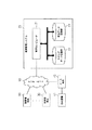
次に、上述した業務フローを実現するためのシステム構成を、図2を用いて説明する。
The sales company sends the parts sent from the manufacturer to the user (W8). The user creates a frame by assembling the received parts (W9).
Next, a system configuration for realizing the business flow described above will be described with reference to FIG.
図2に示すように、販売管理システム20は、インターネット50を介して利用者端末30とメーカ端末40とに接続されている。販売管理システム20は、利用者端末30からの注文データを受信して設計図面を復元し、メーカ端末40に、復元した設計図面と必要なパーツに関する情報とを提供する。
As shown in FIG. 2, the
まず、所望のフレーム構造の組立を行う利用者は、利用者端末30を用いてパーツの発注を行う。この利用者端末30はコンピュータ端末であって、ネットワークを介してデータを送信する機能や、受信したデータを表示する機能等を有する。この利用者端末30は、図示しないCPU、RAM、ROMの他、キーボード、マウス等の入力手段、ディスプレイ等の出力手段、モデム等の通信手段等を有する。この利用者端末30には、フレーム構造の設計及び組立部品の発注を行うための組立部品発注プログラムがインストールされている。
First, a user who assembles a desired frame structure orders parts using the
利用者端末30は、後述する処理(第1の段階、第2の段階、第3の段階、第4の段階、分割位置特定段階等を含む処理)を行う。利用者端末30は、そのための組立部品発注プログラムを実行することにより、利用者端末30は、第1の手段、第2の手段、第3の手段、第4の手段、分割位置特定手段等として機能する。
The
所望のフレーム構造の組立を行う利用者は、まず、利用者端末30を用いて、フレーム構造を設計する。そして、利用者は、利用者端末30を用いて、必要なパーツに関する注文データを販売管理システム20に送信する。
A user who assembles a desired frame structure first designs the frame structure using the
また、メーカ端末40は、フレーム構造の組立に用いられるパーツを製作するメーカで使用されるコンピュータ端末であって、ネットワークを介してデータを送信する機能や、受信したデータを表示する機能等を有する。このメーカ端末40は、図示しないCPU、RAM、ROMの他、キーボード、マウス等の入力手段、ディスプレイ等の出力手段、モデム等の通信手段等を有する。メーカ端末40は、後述する処理(第6の段階等を含む処理)を行う。
The
メーカの担当者は、このメーカ端末40を用いて、販売管理システム20からの発注通知及び設計データの提供を受け付け、必要なパーツを準備し、加工する。
更に、メーカ端末40には、印刷装置41が接続されている。この印刷装置41は、メーカ端末40からの印刷要求に基づいて印刷を行う。
Using the
Further, a
そして、販売管理システム20は、フレーム構造の組立に必要なパーツに関する利用者からの発注を受け付けて、メーカに発注するための各種データの管理及び各種データの提供等の各種データ処理を行う。販売管理システム20は、管理コンピュータ21を備えている。
Then, the
この管理コンピュータ21は、利用者端末30又はメーカ端末40との間でのデータ送受信や、各種情報の管理を実行するためのデータの管理処理等を行う。この管理コンピュータ21は、図示しないCPU、RAM、ROM等を有し、後述する処理(第5の段階等を含む処理)を行う。管理コンピュータ21は、そのための組立部品発注仲介プログラムを実行する。
The
管理コンピュータ21は、カタログデータ記憶部22と、受注データ記憶部23とに接続されている。
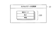
カタログデータ記憶部22には、図3に示すように、部品コード及び長さ毎にカタログデータ220が記録される。このカタログデータ220は、メーカが販売する部品について登録を行った場合に記録される。なお、このカタログデータ220に対応する部品について利用者端末30を用いて選択し、発注することができるように、販売管理システム20は、更新データを利用者端末30に提供する。本実施形態では、カタログデータ220は、部品コード、長さ及び単価を含んで構成される。
The
As shown in FIG. 3, catalog data 220 is recorded in the catalog
部品コードデータ領域には、部品を特定するための識別子としての部品コードに関するデータが記録される。なお、本実施形態では、発注を受け付ける部品が、フレーム部材及び接合部材である場合について説明する。 In the component code data area, data relating to a component code as an identifier for specifying a component is recorded. In the present embodiment, a case will be described in which parts for receiving an order are a frame member and a joining member.
長さデータ領域には、部品コードによって特定される部品が、フレーム部材である場合に、そのフレーム部材の長さに関するデータが記録される。
単価データ領域には、部品コード及び長さによって特定されるパーツの単価に関するデータが記録される。
When the part specified by the part code is a frame member, data relating to the length of the frame member is recorded in the length data area.
In the unit price data area, data related to the unit price of the part specified by the part code and the length is recorded.
受注データ記憶部23には、図4に示すように、受注毎に受注データ230が記録される。この受注データ230は、利用者端末30から注文データを受信した場合に記録される。受注データ230は、受注共通データ231、面構成データ232、及び各パーツについての受注明細データ233を含んで構成される。
In the order
受注共通データ231は、受注番号、顧客コード、及び直送先コードに関するデータを含んで構成される。
受注番号データ領域には、受け付けた注文を特定するための識別子としての受注番号に関するデータが記録される。
The order
In the order number data area, data relating to the order number as an identifier for specifying the accepted order is recorded.
顧客コードデータ領域には、顧客を特定するための識別子としての顧客コードに関するデータが記録される。
直送先コードデータ領域には、パーツの送り先が、顧客コードによって指定される住所以外である場合について、パーツの送り先(直送先)を識別するための識別子としての直送先コードに関するデータが記録される。
In the customer code data area, data relating to a customer code as an identifier for identifying a customer is recorded.
In the direct destination code data area, data related to the direct destination code is recorded as an identifier for identifying the part destination (direct destination) when the part destination is other than the address specified by the customer code. .
面構成データ232としては、後述する設計図面の圧縮データが記録される。
受注明細データ233は、パーツ識別子としてのパーツ番号、部品コード、長さ、及び数量に関するデータを含んで構成される。
As the
The
パーツ番号データ領域には、利用者端末30によって、部品コード及び長さ毎に付番されたパーツ番号に関するデータが記録される。
部品コードデータ領域には、受注した部品の部品コードに関するデータが記録される。
In the part number data area, data relating to a part code and a part number assigned for each length by the
In the part code data area, data related to the part code of the ordered part is recorded.
長さデータ領域には、その部品がフレーム部材である場合に、そのフレーム部材の長さに関するデータが記録される。なお、部品がフレーム部材である場合には、部品コード及び長さが、部品識別子として機能する。一方、部品がフレーム部材以外である場合には、部品コードが部品識別子として機能する。なお、部品がフレーム部材以外である場合については、長さの指定は行わない。 When the part is a frame member, data relating to the length of the frame member is recorded in the length data area. When the component is a frame member, the component code and length function as a component identifier. On the other hand, when the component is other than the frame member, the component code functions as a component identifier. In the case where the component is other than the frame member, the length is not specified.
数量データ領域には、部品コード及び長さによって特定される部品の数量に関するデータが記録される。
上記のように構成されたシステムにおいて、利用者が、フレーム構造の設計を行って必要なパーツについて販売者を介してメーカに発注し、提供されたパーツを用いてフレーム構造の組立を行う場合の処理手順を図5〜図12を用いて説明する。
In the quantity data area, data relating to the quantity of parts specified by the part code and length is recorded.
In the system configured as described above, when the user designs the frame structure, orders the necessary parts from the manufacturer through the seller, and assembles the frame structure using the provided parts. The processing procedure will be described with reference to FIGS.
図5に示すように、まず、利用者は、利用者端末30を用いて、フレーム構造の設計処理を行う(ステップS1−1)。この処理の手順を、図6を用いて説明する。
図6に示すように、利用者端末30を用いて、まず、基本形状の設定を行う(ステップS2−1)。具体的には、まず、利用者が、図7に示す基本装置選択画面60において基本形状の選択を行う。
As shown in FIG. 5, first, the user uses the
As shown in FIG. 6, first, a basic shape is set using the user terminal 30 (step S2-1). Specifically, first, the user selects a basic shape on the basic
図7に示すように、基本装置選択画面60には、装置の基本形状を選択するための基本形状アイコン61が、各基本形状について表示されている。基本形状アイコン61には、基本形状のサンプル画像を表示されている。各基本形状アイコン61の下には、それぞれの基本形状の名称が表示されている。また、基本装置選択画面60には、OKボタン62とキャンセルボタン63とが表示されている。
As shown in FIG. 7, a
ここで、いずれかの基本形状アイコン61を選択してOKボタン62をクリックすると、利用者端末30は、選択された基本形状アイコン61に対応する基本形状の指定に関するデータを記録する。そして、その基本形状について、図8に示す装置設計画面70を表示する。ここでは、「SC標準」の基本形状アイコン61を選択する場合を想定する。この場合、「SC標準」の指定に関するデータが記録され、「SC標準」に関する装置設計画面70が表示される。
Here, when one of the
次に、利用者端末30は、フレーム属性の設定を行う(ステップS2−2)。具体的には、まず、利用者が、装置設計画面70において、装置設計を行う。
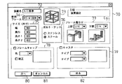
図8に示すように、装置設計画面70には、工程表示部71、装置名表示部72、基本形状表示部73、使用フレーム選択部74、サイズ設定部75、ボルト・ナット選択部76、フレーム重なり設定部77が設けられている。また装置設計画面70には、フレームキャップ選択部78、キャスタ選択部79、次ボタン80、キャンセルボタン81及び戻ボタン82が設けられている。
Next, the
As shown in FIG. 8, the
工程表示部71には、工程として、「装置設計」が表示される。装置名表示部72には、選択された基本形状の名称が表示される。ここでは、「SC標準」が選択されているため、装置名表示部72には、「SC標準」と表示される。基本形状表示部73には、選択された基本形状のサンプル画像が表示される。ここでは、「SC標準」が選択されているため、基本形状表示部73には、SC標準の基本形状のサンプル画像が表示される。使用フレーム選択部74では、使用するフレーム種類の選択を行う。
In the process display unit 71, “apparatus design” is displayed as a process. In the device
サイズ設定部75では、装置のサイズ(外寸)を設定する。このサイズ設定部75には、選択された基本形状について、各部のサイズの設定を行うための入力部が設けられている。ここでは、「SC標準」が選択されているため、「SC標準」の各部のサイズの設定を行うための入力部が設けられている。「SC標準」については、具体的には、幅、奥行き、高さ(「高さ1」、「高さ2」)について、サイズを設定する。ここで、「高さ1」は、全体の高さを示す。一方、「高さ2」は、フレームで区切られた下部の高さを示す。ここでは、幅、奥行き、高さ1、高さ2として、それぞれ、「900」、「900」、「900」、「450」を設定する。
The
ボルト・ナット選択部76には、ボルト及びナットの材質を選択するための選択ボタンが設けられている。ここでは、「スチール」を選択する。フレーム重なり設定部77では、上部及び下部について、それぞれフレーム部材の組み方を選択するための選択ボックス
が設けられている。そして、上部及び下部についての各選択ボックスの下には、選択された組み方によるフレーム部材の重なりのイメージが表示される。ここでは、上部及び下部について、それぞれ縦のフレーム部材が突き抜けた形態でフレーム部材が重なるように、フレーム重なりをそれぞれ選択する。
The bolt /
フレームキャップ選択部78には、フレームキャップを用いるかどうかについてのフレームキャップ使用チェックボタン、色に関する選択ボックス、補正に関するチェックボタン、及びイメージ表示部が設けられている。ここで、フレームキャップ使用チェックボタンを選択すると、フレームキャップ選択部78の他の入力項目について入力を行うことができる。なお、ここでは、フレームキャップ選択部78での入力は行わない。 The frame cap selection unit 78 is provided with a frame cap use check button as to whether or not to use a frame cap, a color selection box, a correction check button, and an image display unit. Here, if the frame cap use check button is selected, the other input items of the frame cap selection unit 78 can be input. Here, the input in the frame cap selection unit 78 is not performed.
キャスタ選択部79には、キャスタを用いるかどうかについてのキャスタ使用チェックボタン、タイプ選択部、個数選択部、及びイメージ表示部が設けられている。ここで、キャスタ使用チェックボタンを選択すると、キャスタ選択部79の他の入力項目について入力を行うことができる。なお、ここでは、キャスタ選択部79での入力は行わない。
The
次ボタン80は、次画面に移行する場合に用いる。キャンセルボタン81は、設計処理を中止する場合に用いる。戻ボタン82は、基本装置選択画面60に戻る場合に用いる。ここでは、利用者は、上記のように設定を行い、次ボタン80をクリックする。これにより、利用者端末30は、装置名、使用フレーム、サイズ、ボルト・ナット、フレーム重なり、フレームキャップ及びキャスタに関する装置設計データを記録する。そして、利用者端末30は、図9に示す面設定画面90を表示する。
The
次に、利用者端末30は、基本形状を構成する各構成面の属性の設定を行う(ステップS2−3)。具体的には、まず、利用者が、面設定画面90において各構成面の属性を設定するための入力を行う。
Next, the
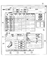
図9に示すように、面設定画面90には、工程表示部91、装置名表示部92、サイズ表示部93、フレーム面設定部94、全体イメージ表示部95、面表示部96、定義一覧表示部97、定義詳細設定部98、接合部材表示部99が設けられている。さらに、面設定画面90には、定義ボタン100、削除ボタン101、復帰ボタン102、確定ボタン103、OKボタン104、プレビューボタン105、キャンセルボタン106、及び戻ボタン107が設けられている。
As shown in FIG. 9, the
工程表示部91には、工程として、「面設定」が表示される。装置名表示部92には、選択された基本形状の名称が表示される。ここでは、「SC標準」が選択されているため、装置名表示部92には、「SC標準」と表示される。
In the
サイズ表示部93には、装置設計画面70のサイズ設定部75で設定された、幅、奥行き、高さ(「高さ1」、「高さ2」)についてのサイズが表示される。ここでは、幅、奥行き、高さ1、高さ2として、それぞれ、「900」、「900」、「900」、「450」が表示される。
The
フレーム面設定部94では、選択された基本装置について、フレーム構造の各面についての設定内容が各行に表示される。ここでは、基本装置として「SC標準」が選択されているため、各行には、「天井」、「前面」、「右側面」、「背面」、「左側面」、「中面」、「下前面」、「下右面」、「下背面」、「下左面」、「底面」の設定内容がそれぞれ表示される。このフレーム面設定部94では、各面について、各項目の設定を行う。フレーム面設定部94で設定されたデータは、面毎にフレーム面データとして記録される。
The frame
全体イメージ表示部95には、選択された基本装置についての全体イメージが表示される。ここでは、基本装置として「SC標準」が選択されているため、SC標準の基本装置の全体イメージが表示されている。さらに、全体イメージ表示部95では、フレーム面設定部94において選択されている面に斜線が付される。ここでは、フレーム面設定部94において「右側面」が選択されており、全体イメージ表示部95において、「右側面」に対応する部分に斜線が付される。
The overall
面表示部96には、フレーム面設定部94において選択されている面について、フレーム面設定部94における分割数についての設定内容に従って、分割された面のイメージが表示される。ここでは、フレーム面設定部94において、「右側面」についての分割数として「横2分割」が設定されているため、面表示部96では、中柱により、面が横に2分割され、各分割面に「1」、「2」とそれぞれ付番されている。面表示部96における各分割面「1」、「2」の付番は、フレーム面設定部94における分割面1、分割面2に対応する。なお、フレーム面設定部94の「右側面」の端面距離1では、左端から中柱までの距離を指定する。ここでは、「450」を指定している。
The
定義一覧表示部97には、面定義について、定義名称毎に、属性及び接続方法が表示される。ここでは、定義名称「0」について、属性として「開口」、接続方法として「ブラケット」がそれぞれ設定されている。この定義一覧で設定されたデータは、定義名毎に、定義データとして記録される。
The definition
定義詳細設定部98では、フレーム面設定部94において選択されている面についての定義の設定、及び、定義一覧表示部97に表示される定義の設定を行う。
ここでは、フレーム面設定部94において選択されている「右側面」についての定義の詳細設定が表示されている。「右側面」については、「分割面1」で「0」が設定されている。そして、定義一覧の定義名称「0」に対応して面属性「開口」及び接続方法「ブラケット」が表示される。また、「頂点」については、「1−左下」が基準となる頂点として設定されている。これは、面表示部96に示す分割面「1」の左下の頂点を示す。さらに、ブラケットタイプ「厚型」及びタップ穴「無」が設定されている。この定義詳細設定部98では、面表示部96において選択された構成面について定義情報を設定する。この定義詳細設定部98で設定されたデータは、構成面毎に、面定義詳細データとして記録される。
The definition
Here, the detailed setting of the definition for the “right side” selected in the frame
なお、定義一覧表示部97に表示される定義を新たに設定する場合、まず、定義ボタン100をクリックする。これにより、定義詳細設定部98の項目欄に、定義名、面属性、及び接続方法が表示される。利用者は、これらの項目欄に対応する現在の値欄において、設定入力を行う。ここで、利用者は、まず、定義名を入力する。そして、面属性を選択入力すると、接続方法として、その面属性に対応する接続方法の選択入力が可能となる。そして、接続方法について選択入力すると、入力された面属性及び接続方法に対応して選択すべき事項が項目欄に表示される。利用者は、項目欄の各事項について、現在の値欄に設定入力を行う。そして、確定ボタン103をクリックすると、定義詳細設定部98において入力した内容で、定義が設定され、定義データが記録されるとともに、その定義について定義一覧表示部97に表示される。
When a definition displayed on the definition
接合部材表示部99には、設定されている接続方法による接合部材のイメージ図が表示される。ここでは、定義詳細設定部98において接続方法「ブラケット」が設定されているため、ブラケットのイメージ図が表示される。
The joining
定義ボタン100は、上述のように、新たに定義設定を行う場合に用いる。削除ボタン101は、設定した定義を削除する場合に用いる。定義一覧表示部97において、定義を
選択して削除ボタン101をクリックすると、選択されていた定義が、定義一覧表示部97から消去される。復帰ボタン102は、削除した定義データを復帰させる場合に用いる。この復帰ボタン102をクリックすると、一旦、定義一覧表示部97から消去された定義が再表示される。確定ボタン103は、上述のように、定義詳細設定部98において定義の設定入力を行った場合に、その定義を登録する場合に用いる。
The
OKボタン104は、設定内容で登録を行い、設定図を作成して表示させる場合に用いる。プレビューボタン105は、その時点の設定内容でプレビューする場合に用いる。キャンセルボタン106は、面設定画面90で設定した内容を取り消す場合に用いる。戻ボタン107は、装置設計画面70に戻る場合に用いる。
The
利用者は、全部の面についての定義の設定を終了するまで、面設定画面90における設定操作を繰り返す。これにより、利用者端末30は、すべての構成面についての定義の設定が終了しない限り、ステップS2−3の処理を繰り返す(ステップS2−4においてNO)。
The user repeats the setting operation on the
そして、利用者は、全部の面についての定義を終了すると、OKボタン104をクリックする。これにより、利用者端末30は、面定義の設定が終了したかどうかを調べる。具体的には、装置設計データ、フレーム面データ、面定義詳細データを調べ、フレーム構造を組み立てるために必要なデータがすべて記録されているかどうかを調べる。ここで、必要なデータがすべて記録されている場合、すべての構成面についての定義の設定が終了したこととなる。
The user clicks the
すべての構成面についての定義の設定が終了した場合(ステップS2−4においてYESの場合)、利用者端末30は、まず、カタログ部品の特定を行う(ステップS2−5)。具体的には、利用者端末30は、装置設計データに含まれる使用するフレーム部材に関するデータ、ボルト・ナットに関するデータ、フレームキャップに関するデータ、及びキャスタに関するデータに基づいて、カタログ部品を特定する。
When the definition settings for all the component surfaces have been completed (YES in step S2-4), the
ここでは、使用するフレーム部材として「HFS6−3030」が記録されている。また、接続部材としてのボルト・ナットについて「スチール」が記録されている。なお、フレームキャップに関するデータ及びキャスタに関するデータは記録されていない。このため、カタログ部品として、使用するフレーム部材について「HFS−6030」が特定される。接続部材については、スチール製の接続部材であって、面定義詳細データにおける設定内容に対応する接続部材が特定される。 Here, “HFS6-3030” is recorded as the frame member to be used. In addition, “steel” is recorded for bolts and nuts as connecting members. Note that data relating to frame caps and data relating to casters are not recorded. For this reason, “HFS-6030” is specified for the frame member to be used as the catalog part. The connection member is a steel connection member, and the connection member corresponding to the setting content in the surface definition detailed data is specified.
次に、利用者端末30は、各構成面のデータに基づいて部品の加工形状の特定を行う(ステップS2−6)。ここで、部品の加工形状の特定とは、切断後のフレーム部材の特定や、接合部において加工が必要な場合についてフレーム部材における加工形状の特定をいう。フレーム部材については、メーカ側では、原型としての切断前のフレーム部材が用意されているため、用意されているフレーム部材を、利用者側で特定された長さ(加工形状)に切断して提供することとなる。
Next, the
ここで、利用者端末30は、装置設計データ、フレーム面データ、及び面定義詳細データに基づいて、装置を構成する各フレーム部材の長さ、及び接合部の位置を特定する。具体的には、利用者端末30は、装置設計データの幅、奥行き、高さ1、及び高さ2のサイズに関するデータと、フレーム重なりに関するデータとに基づいて、各フレーム部材の長さを特定する。ここで、分割されている面を構成するフレーム部材については、フレーム面データを用いて、各フレーム部材の長さを特定する。そして、利用者端末30は、各フレーム部材について、フレーム部材の部品コード及び長さに関するデータを含むフレーム
長データを記録する。さらに、装置設計データ、フレーム面データ、面定義詳細データを用いて、接合部の位置を特定する。
Here, the
次に、利用者端末30は、パーツ番号の付与を行う(ステップS2−7)。具体的には、同一の部品コードで同一の長さのフレーム部材について同一のパーツ番号を付与する。また、同一の接続部材について同一のパーツ番号を付与する。さらに、利用者端末30は、パーツ番号毎に、パーツの個数を求める。そして、利用者端末30は、パーツ番号毎に、パーツ番号と、部品を特定するデータと、パーツの個数に関するデータとを含むパーツ番号データを記録する。ここで、部品を特定するデータとしては、フレーム部材については、フレーム部材の部品コード及び長さに関するデータを記録し、接合部材については、部品コードに関するデータを記録する。
Next, the
そして、利用者端末30は、設計図面データを生成する(ステップS2−8)。具体的には、利用者端末30は、装置設計データ、フレーム面データ、面定義詳細データと、特定した各フレーム部材の長さ及び接合部の位置と、付与したパーツ番号とを用いて、設計図面を表示するためのデータを生成する。ここで、設計図面として、斜視図、天井面図、正面図、右側面図、背面図、左側面図、及び底面図を作成する。そして、利用者端末30は、設計図面データに基づいて、図10に示す設計図表示画面110を表示する。
Then, the
図10に示すように、設計図表示画面110には、斜視図111、天井面図112、正面図113及び右側面図114が表示される。また、設計図表示画面110には、三面図アイコン115が設けられており、この三面図アイコン115をクリックすると、天井面図112、正面図113及び右側面図114の表示が、背面図、左側面図及び底面図の表示に切り替わる。なお、再度、三面図アイコン115をクリックすると、天井面図112、正面図113及び右側面図114の表示に切り替わる。
As shown in FIG. 10, a
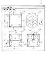
斜視図111では、装置設計データに含まれるサイズに関するデータに基づいて、幅「900」、奥行「900」、高さ1「900」、高さ2「450」の各サイズを表示する。天井面図112では、装置設計データに含まれるサイズに関するデータに基づいて、奥行のサイズとして「900」を表示する。正面図113では、装置設計データに含まれるサイズに関するデータに基づいて、幅「900」、高さ1「900」及び高さ2「450」の各サイズを表示する。右側面図114では、フレームデータに含まれる端面距離1に関するデータに基づいて、端面距離1として「450」を表示する。そして、パーツ番号データに基づいて、付与したパーツ番号を各フレーム及び接合部に関連付けて表示する。
In the
次に、利用者は、設計図表示画面110の左上部の「ファイル」のプルダウンメニューを用いて発注書の作成要求を行う。これにより、利用者端末30は、発注書の作成のための処理を行う。ここで、利用者端末30は、まず、図5に示すように、面構成データの圧縮情報の生成を行う(ステップS1−2)。具体的には、利用者端末30は、装置設計データ、フレーム面データ、面定義詳細データを用いて、形状データの圧縮情報を生成する。そして、利用者端末30は、図11に示す発注書130を表示するためのデータを生成する。
Next, the user makes a purchase order creation request using the “file” pull-down menu at the upper left of the design
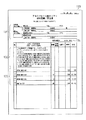
図11に示すように、発注書130には、顧客表示欄131、形状データ圧縮情報表示欄132、部材表示欄133、及び合計金額表示欄134が設けられている。
顧客表示欄131には、発注を行う顧客に関する情報と、直送先に関する情報とが表示される。なお、これらの情報は、設定のプルダウンメニューの「お客様情報」を用いて表示される画面において予め入力し、顧客データを記録しておく。この顧客データに基づいて、顧客表示欄131に各情報が表示される。
As shown in FIG. 11, the
In the
形状データ圧縮情報表示欄132には、生成した面構成データの圧縮情報が表示される。部材表示欄133には、パーツ番号毎に、パーツ番号、カタログ記号、数量、単価、及び小計が表示される。パーツ番号、カタログ記号、及び数量は、パーツ番号データに基づいて表示される。カタログ記号は、フレーム部材については、部品コードと長さとがまとめて表示される。例えば、部品コードが「HFS6−3030」で長さが420mmの場合、カタログ記号は、「HFS6−3030−420」と表示される。ここで、部品コード及び長さは、パーツ番号データに基づいて表示される。一方、接合部材に関しては、パーツ番号データの部品コードに基づいて、部品コードがカタログ記号として表示される。単価は、予め記録されている単価データに基づいて表示される。小計は、個数と単価とに基づいて算出されて表示される。合計金額表示欄134には、部材表示欄133における小計の合計が算出されて表示される。
In the shape data compression
利用者は、この発注書130の記載内容を確認し、発注を行う。具体的には、利用者は、利用者端末30を用いて、発注書130に関するデータ(注文データ)について管理コンピュータ21への送信要求を行う。これにより、利用者端末30は、注文データを管理コンピュータ21に送信する(ステップ1−3)。
The user confirms the contents of the
この注文データを受信すると、まず、管理コンピュータ21は、この注文データに基づいて、受注データ230を受注データ記憶部23に記録する(ステップS1−4)。ここで、管理コンピュータ21は、受注番号を付与し、受注共通データ231の受注番号として記録する。また、発注書130の顧客表示欄131の顧客コードと直送先コードとを、それぞれ受注共通データ231の顧客コード及び直送先コードとして記録する。さらに、形状データ圧縮情報表示欄132の面構成データの圧縮情報を面構成データ232として記録する。また、部材表示欄133のパーツ番号、カタログ記号、及び数量に基づいて、パーツ番号、部品コード、長さ、及び数量に関するデータを受注明細データ233の各データ領域に記録する。ここで、部品コード及び長さについては、カタログ記号を部品コードと長さとに分解してそれぞれ記録する。
When this order data is received, first, the
そして、管理コンピュータ21は、面構成データに基づいて設計図面の復元処理を行う(ステップS1−5)。具体的には、管理コンピュータ21は、形状データ圧縮情報表示欄132の面構成データの圧縮情報に基づいて記録した面構成データ232に基づいて、設計図面を復元する。
Then, the
そして、管理コンピュータ21は、カタログ部品と設計図面とを記録する(ステップS1−6)。具体的には、管理コンピュータ21は、復元した設計図面を表示するための設計図面表示データと、その設計図面に対応するカタログ部品に関するデータとを、それぞれ受注番号に関連付けて記録する。
Then, the
そして、管理コンピュータ21は、発注通知をメーカ端末40に送信する(ステップS1−7)。具体的には、管理コンピュータ21は、発注コードを含む発注通知のための電子メールをメーカ端末40を使用するメーカの電子メールアドレスに送信する。なお、管理コンピュータ21は、この発注コードを、受注共通データ231に記録した受注番号に対応付けて記録する。
Then, the
メーカの担当者は、この発注通知を確認すると、メーカ端末40において、データ要求のための操作を行う。これにより、メーカ端末40は、設計データに関するデータ要求を管理コンピュータ21に送信する(ステップS1−8)。このデータ要求のためのデータには、発注コードが含まれる。
When the person in charge of the manufacturer confirms this order notification, the manufacturer performs an operation for requesting data at the
管理コンピュータ21は、このデータ要求を受信すると、発注コードに基づいて受注番
号を取得し、この受注番号に基づいて、カタログ部品に関するデータと設計図面表示データとを抽出する。そして、この設計データをメーカ端末40に提供する(ステップS1−9)。
Upon receiving this data request, the
この設計データを受信すると、メーカ端末40は、この設計データに基づいて、カタログ部品と設計図面とを表示する(ステップS1−10)。メーカの担当者は、このカタログ部品の表示と設計図面とを確認し、メーカ端末40において部品ラベルの印刷要求を行う。これにより、メーカ端末40は、カタログ部品に関するデータに基づいて、部品ラベルの印刷データを生成し、印刷装置41を用いて、図12に示すパーツ添付シール150の印刷を行う(ステップ1−11)。
When receiving the design data, the
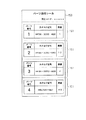
図12に示すように、パーツ添付シール150には、発注コードが表示され、パーツ番号毎に、部品ラベル151が設けられている。各部品ラベル151には、パーツ番号、カタログ記号及び数量が表示される。なお、各部品ラベル151のパーツ番号、カタログ記号及び数量は、発注書130の部材表示欄133の各パーツについての記載に対応する。
As shown in FIG. 12, an order code is displayed on the
そして、図4に示すように、メーカは、設計図面に基づいて、パーツを準備し(W5)、フレーム部材について、必要な加工を施す(W6)。具体的には、カタログ記号に含まれる部品コードに基づいて、加工前のフレーム部材を用意し、カタログ記号に含まれる長さの指定に基づいて、そのフレーム部材を切断する。なお、接合部位について加工すべき旨の指定がある場合には、接合部位についての加工を行う。そして、メーカは、パーツ番号毎に各パーツをまとめて、そのパーツ番号に対応する部品ラベル151を添付する。そして、メーカは、部品ラベル151を添付した加工後のパーツを販売会社に発送する(W7)。
Then, as shown in FIG. 4, the manufacturer prepares parts based on the design drawing (W5) and performs necessary processing on the frame member (W6). Specifically, a frame member before processing is prepared based on the part code included in the catalog symbol, and the frame member is cut based on the designation of the length included in the catalog symbol. In addition, when there exists designation | designated to process about a junction part, the process about a junction part is performed. The manufacturer collects the parts for each part number and attaches a
販売会社は、メーカから送られたパーツを利用者に発送する(W8)。具体的には、受注データ230の顧客コード又は直送先コードに基づいて、顧客データ記憶部から発送先情報を抽出し、その発送先にパーツを発送する。ここで、直送先コードが記録されている場合は、直送先コードに基づいて抽出した発送先に発送し、直送先コードが記録されていない場合、顧客コードに基づいて抽出した発送先に発送する。
The sales company sends the parts sent from the manufacturer to the user (W8). Specifically, based on the customer code or direct destination code of the
利用者は、発送されたパーツを受け取ると、そのパーツを用いてフレーム構造を組み立てる(W9)。ここで、利用者は、設計図表示画面110の設計図面に表示されているパーツ番号と、受け取ったパーツに添付されているパーツ番号とを照合して、各パーツの配置を確認する。そして、利用者は、設計図表示画面110の設計図面に従って、フレーム構造を組み立てる。
When the user receives the sent-out part, the user assembles a frame structure using the part (W9). Here, the user collates the part number displayed on the design drawing of the design
以上、本実施形態によれば、以下に示す効果を得ることができる。
・ 上記実施形態では、利用者端末30は、装置のフレーム構造を特定し、そのフレーム構造を構成する各部品を特定し、特定された各部品の種類毎に、それぞれ特定のパーツ番号を付与する。そして、そのフレーム構造の設計図面を生成し、その設計図面において、各部品に関連付けてパーツ番号を表示するための設計図面データを生成する。そして、各部品の種類毎のパーツ番号、部品コード及び長さに関する情報を有するカタログ記号、及び数量に関するデータを含む注文データを管理コンピュータ21に送信する。そして、管理コンピュータが、パーツ番号、カタログ記号及び数量に関するデータをメーカ端末40に送信する。そして、メーカ側で、パーツ番号毎に、パーツ番号、カタログ記号、及び数量を含むラベルを出力する。
As described above, according to the present embodiment, the following effects can be obtained.
In the above embodiment, the
このため、利用者は、利用者端末30を用いて、装置の設計を容易に行うことができるとともに、その装置を組み立てるために必要な部品を容易に特定して、利用者端末30に
より生成された注文データにより発注することができる。
For this reason, the user can easily design the device using the
一方、メーカは、出力されたパーツ番号、カタログ記号及び数量を含むラベルを用いて、利用者に提供する部品を効率的に用意できる。また、メーカは、ラベルに印刷された数量により、各パーツ番号に対応する部品の数量を確認できる。 On the other hand, the manufacturer can efficiently prepare parts to be provided to the user by using a label including the output part number, catalog symbol, and quantity. In addition, the manufacturer can confirm the quantity of parts corresponding to each part number from the quantity printed on the label.
さらに、メーカが、パーツ番号毎のラベルを、そのパーツ番号に対応する部品に添付することで、利用者は、そのラベルのパーツ番号と、設計図面のパーツ番号とを照合することにより、組み立てるフレーム構造における部品の配置を容易に特定できる。 Furthermore, the manufacturer attaches a label for each part number to the part corresponding to the part number, and the user can assemble the frame by collating the part number of the label with the part number of the design drawing. The arrangement of parts in the structure can be easily specified.
・ 上記実施形態では、利用者端末30は、装置のフレーム構造の設計図面を生成し、その設計図面において、各部品に関連付けてパーツ番号を表示するための設計図面データを生成し、その設計図面を復元可能なデータを生成する。そして、その設計図面を復元可能なデータを含む注文データを管理コンピュータ21に送信する。そして、管理コンピュータが、注文データに基づいて、設計図面を復元し、設計図面を表示するためのデータを生成し、そのデータをメーカ端末40に送信する。そして、メーカ側で、設計図面を表示する。このため、メーカは、復元された設計図面を用いて、利用者に提供する部品を効率的に用意できる。
In the above embodiment, the
・ 上記実施形態では、利用者端末30は、フレーム構造の構成面の属性情報を設定し、構成面の属性情報に基づいて、フレーム部材については、部品コードと長さを特定し、部品コードと長さ毎に、パーツ番号を付与する。このため、利用者は、構成面の属性情報を設定することにより、容易に、使用する部品や、フレーム部材の長さの特定のための操作を行うことができる。一方、メーカは、部品コード及び長さ毎にパーツ番号が付与されているため、部品コードによって特定されるフレーム部材についての加工(切断)についての判断を容易に行うことができる。従って、メーカは、各フレーム部材の長さ毎の数量に基づいて、効率的に、加工後(適当な長さに切断後)のフレーム部材を提供できる。
In the above embodiment, the
・ 上記実施形態では、利用者端末30は、基本形状を特定し、基本形状の構成面を特定して、その構成面の分割位置を特定する。そして、基本形状において、特定された構成面を特定された分割位置で分割したフレーム構造を特定する。このため、いずれかの構成面が分割されているフレーム構造を組み立てる場合に、容易に、フレーム構造を特定することができる。そして、そのフレーム構造を組み立てるために必要な部品を特定できる。
In the above embodiment, the
・ 上記実施形態では、利用者端末30は、特定した構成面の基準となる頂点を特定し、その頂点を含む端面を特定し、その端面からの距離を特定することにより、分割位置を特定する。このため、利用者は、分割する構成面について、その構成面の基準となる頂点を含む端面からの距離を特定することにより、容易に構成面の分割位置を特定することができる。
In the above-described embodiment, the
・ 上記実施形態では、利用者端末30は、発注書130のデータをインターネット50を介して管理コンピュータ21に送信する。このため、利用者は、発注書130により発注内容を容易に確認できるとともに、容易に発注を行うことができる。
In the above embodiment, the
・ 上記実施形態では、販売管理システム20が、利用者端末30からの注文データに基づいて、設計データをメーカ端末40に提供する。このため、メーカ側は、販売管理システム20からの指示に従って、部品を加工して販売会社に提供すればよく、効率的に部品の提供を行うことができる。
In the above embodiment, the
なお、上記実施形態は、以下の態様に変更してもよい。
○ 上記実施形態では、利用者端末30は、発注書130をインターネット50を介して管理コンピュータ21に送信した。これに代えて、発注書130を印刷してファクシミリにより管理コンピュータ21の管理を行う販売会社に送信してもよい。この場合、販売会社側で、ファクシミリ受信した発注書130の内容を管理コンピュータ21に投入する。この場合も、形状データ圧縮情報表示欄132に記載の面構成データの圧縮情報を用いれば、設計図面を復元できる。これにより、利用者端末30がインターネット50に接続されていない場合であっても、利用者端末30により作成した発注書130に基づいて、メーカ端末40に設計データを提供できる。
In addition, you may change the said embodiment into the following aspects.
In the above embodiment, the
○ 上記実施形態では、利用者端末30は、面構成データの圧縮情報を記載した形状データ圧縮情報表示欄132を含む発注書130をインターネット50を介して管理コンピュータ21に送信した。これに代えて、設計図面データを管理コンピュータ21に送信してもよい。これにより、利用者端末30による面構成データの圧縮データの作成と、管理コンピュータ21による設計図面の復元を行う必要がなくなる。
In the above embodiment, the
○ 上記実施形態では、販売会社が管理する管理コンピュータ21が、メーカ端末40に設計データを提供し、メーカが部品の加工を行って、部品ラベル151を添付して販売会社に発送した。そして、販売会社が、その部品を利用者に発送した。これに代えて、部品の加工及び販売を行うメーカが、販売管理システム20を備え、注文データの受け付け、及び部品の加工・販売を行ってもよい。
In the above embodiment, the
○ 上記実施形態では、特定のメーカが、フレーム部材等の部品を提供し、管理コンピュータ21は、特定のメーカ端末40に設計データを提供した。これに代えて、複数のメーカが、それぞれ部品を提供してもよい。この場合、1つのフレーム構造を組み立てるための各部品を、それぞれ異なるメーカが提供してもよい。この場合、管理コンピュータ21は、複数のメーカに対し、そのメーカの部品を特定して、それぞれ設計データを提供する。そして、各メーカでは、そのメーカで提供する部品に関する部品ラベルのみを印刷するようにする。そして、各メーカから発送された部品を、販売会社がまとめて、利用者に発送してもよい。これにより、利用者は、使用する部品について、選択の幅が広がる。
In the above embodiment, a specific manufacturer provides parts such as frame members, and the
21…管理コンピュータ、30…利用者端末、40…部品提供者端末としてのメーカ端末。 21 ... Management computer, 30 ... User terminal, 40 ... Manufacturer terminal as a component provider terminal.
Claims (11)
前記利用者端末が、
フレーム構造を特定する第1の段階と、
前記フレーム構造を構成する各部品を特定し、特定された各部品の種類毎に、それぞれ特定のパーツ識別子を付与する第2の段階と、
前記フレーム構造の設計図面を生成し、その設計図面に前記各部品に関連付けて前記パーツ識別子を表示するための設計図面データを生成する第3の段階と、
前記各部品の種類毎の前記パーツ識別子、部品識別子、及び数量に関する情報を含む注文情報を生成する第4の段階と、
前記管理コンピュータが、
前記注文情報を受け付けて、この注文情報に基づいて、前記パーツ識別子、部品識別子、及び数量に関するデータとを前記部品提供者端末に送信する第5の段階と、
前記部品提供者端末が、
前記パーツ識別子と前記部品識別子と前記数量とを関連付けて出力し、前記パーツ識別子毎に前記パーツ識別子を含むラベルを印刷するための処理を行う第6の段階と
を備えたことを特徴とする組立部品発注方法。 A method for ordering assembly parts using a user terminal, a parts provider terminal, and a management computer,
The user terminal is
A first step of identifying a frame structure;
A second step of identifying each component constituting the frame structure and assigning a specific part identifier for each type of each identified component;
Generating a design drawing of the frame structure, and generating design drawing data for displaying the part identifier in association with each part in the design drawing;
A fourth step of generating order information including information on the part identifier, part identifier, and quantity for each type of each part;
The management computer is
A fifth step of receiving the order information and transmitting the part identifier, the part identifier, and data relating to the quantity to the parts provider terminal based on the order information;
The component provider terminal is
An assembly comprising: a step of outputting the part identifier, the part identifier, and the quantity in association with each other and performing a process for printing a label including the part identifier for each part identifier; How to order parts.
前記設計図面データに基づいて、前記設計図面を復元可能な情報を生成する段階と、
前記管理コンピュータが、
前記設計図面を復元可能な情報を受け付けて、前記設計図面を復元可能な情報に基づいて、前記設計図面を復元し、前記設計図面を表示するための設計図面表示データを生成し、前記設計図面表示データを前記部品提供者端末に送信する段階と、
前記部品提供者端末が、
前記設計図面表示データに基づいて前記設計図面を出力する段階と
をさらに備えたことを特徴とする請求項1に記載の組立部品発注方法。 The user terminal is
Generating information capable of restoring the design drawing based on the design drawing data;
The management computer is
Receiving information capable of restoring the design drawing, restoring the design drawing based on information capable of restoring the design drawing, generating design drawing display data for displaying the design drawing, and the design drawing Transmitting display data to the component provider terminal;
The component provider terminal is
The assembly part ordering method according to claim 1, further comprising: outputting the design drawing based on the design drawing display data.
前記部品が前記部品の原型の加工形状である場合は、前記部品識別子は、前記部品の原型を特定する原型識別子と前記加工形状の特定情報とを含み、
前記第2の段階は、
前記フレーム構造の構成面の属性情報を設定する段階と、
前記構成面の属性情報に基づいて部品を特定する段階と、
前記部品毎に、前記パーツ識別子を付与する段階と
を備え、
構成面の属性情報に基づいて部品を特定する段階は、
前記部品が前記原型の加工形状である場合、前記部品を前記原型と前記加工形状とにより特定することを特徴とする請求項1又は2に記載の組立部品発注方法。 The part includes an original processing shape of the part,
When the part is a processed shape of the prototype of the part, the component identifier includes a prototype identifier that identifies the prototype of the part and identification information of the processed shape,
The second stage includes
Setting attribute information of the structural surface of the frame structure;
Identifying a part based on attribute information of the component surface;
Providing the part identifier for each part;
The stage of identifying a part based on the attribute information of the component surface is
3. The assembly part ordering method according to claim 1, wherein, when the part has a processed shape of the prototype, the part is specified by the prototype and the processed shape.
基本形状を特定する段階と、
前記基本形状の構成面を特定して、その構成面の分割位置を特定する分割位置特定段階とを備え、
前記基本形状において、前記特定された構成面を前記特定された分割位置で分割したフレーム構造を特定することを特徴とする請求項1〜3のいずれか1つに記載の組立部品発注方法。 The first stage includes
Identifying the basic shape;
Identifying a component surface of the basic shape, and a division position specifying step of identifying a division position of the component surface,
The assembly part ordering method according to any one of claims 1 to 3, wherein in the basic shape, a frame structure obtained by dividing the specified component surface at the specified division position is specified.
前記特定した構成面の基準となる頂点を特定し、前記頂点を含む端面を特定し、その端面からの距離を特定することにより、分割位置を特定することを特徴とする請求項4に記載の組立部品発注方法。 The division position specifying step includes:
5. The division position is specified by specifying a vertex serving as a reference of the specified component surface, specifying an end surface including the vertex, and specifying a distance from the end surface. Assembly part ordering method.
前記利用者端末を、
フレーム構造を特定する第1の手段と、
前記フレーム構造を構成する各部品を特定し、特定された各部品の種類毎に、それぞれ特定のパーツ識別子を付与する第2の手段と、
前記フレーム構造の設計図面を生成し、その設計図面に前記各部品に関連付けて前記パーツ識別子を表示するための設計図面データを生成する第3の手段と、
前記パーツ識別子毎に前記パーツ識別子を含むラベルを前記部品提供者端末に印刷させ、前記パーツ識別子と部品識別子と数量とを関連付けて前記部品提供者端末に出力させるための前記パーツ識別子、部品識別子及び数量に関する情報を前記管理コンピュータに入力するための注文情報を出力する第4の手段
として機能させるための組立部品発注プログラム。 An assembly part ordering program for a user to place an order for an assembly part using the user terminal, using a user terminal, a parts provider terminal, and a management computer,
The user terminal is
A first means for specifying a frame structure;
A second means for identifying each component constituting the frame structure and assigning a specific part identifier for each type of each identified component;
A third means for generating a design drawing of the frame structure, and generating design drawing data for displaying the part identifier in association with each part in the design drawing;
For each part identifier, a label including the part identifier is printed on the parts provider terminal, and the parts identifier, the part identifier, An assembly part ordering program for functioning as a fourth means for outputting order information for inputting information relating to the quantity to the management computer.
前記設計図面データに基づいて、前記設計図面を復元可能な情報を生成する手段と、
前記設計図面を前記部品提供者端末に出力させるための前記設計図面を復元可能な情報を前記管理コンピュータに入力するための注文情報を出力する手段
として機能させることを特徴とする請求項6に記載の組立部品発注プログラム。 The user terminal is
Means for generating information capable of restoring the design drawing based on the design drawing data;
7. The information processing apparatus according to claim 6, further comprising: function for outputting order information for inputting information capable of restoring the design drawing for causing the parts provider terminal to output the design drawing to the management computer. Assembly parts ordering program.
前記部品が前記部品の原型の加工形状である場合は、前記部品識別子は、前記部品の原型を特定する原型識別子と前記加工形状の特定情報とを含み、
前記第2の手段を、
前記フレーム構造の構成面の属性情報を設定する手段と、
前記構成面の属性情報に基づいて部品を特定する手段と、
前記部品毎に、前記パーツ識別子を付与する手段
として機能させ、
構成面の属性情報に基づいて部品を特定する手段は、
前記部品が前記原型の加工形状である場合、前記部品を前記原型と前記加工形状とにより特定することを特徴とする請求項6又は7に記載の組立部品発注プログラム。 The part includes an original processing shape of the part,
When the part is a processed shape of the prototype of the part, the component identifier includes a prototype identifier that identifies the prototype of the part and identification information of the processed shape,
The second means,
Means for setting attribute information of the structural surface of the frame structure;
Means for identifying a component based on the attribute information of the component surface;
For each part, function as a means to give the part identifier,
A means for identifying a part based on the attribute information of the component surface is:
The assembly part ordering program according to claim 6 or 7, wherein, when the part has a machining shape of the prototype, the part is specified by the prototype and the machining shape.
基本形状を特定する手段と、
前記基本形状の構成面を特定して、その構成面の分割位置を特定する分割位置特定手段として機能させ、
前記基本形状において、前記特定された構成面を前記特定された分割位置で分割したフレーム構造を特定することを特徴とする請求項6〜8のいずれか1つに記載の組立部品発注プログラム。 The first means;
Means for identifying the basic shape;
Specify the component surface of the basic shape, and function as a division position specifying means for specifying the division position of the component surface,
The assembly part ordering program according to any one of claims 6 to 8, wherein a frame structure obtained by dividing the specified component surface at the specified division position is specified in the basic shape.
前記特定した構成面の基準となる頂点を特定し、前記頂点を含む端面を特定し、その端面からの距離を特定することにより、分割位置を特定する手段として機能させることを特徴とする請求項9に記載の組立部品発注プログラム。 The division position specifying means,
The vertices serving as a reference of the specified component surface are specified, an end surface including the vertex is specified, and a distance from the end surface is specified to function as means for specifying a division position. 9. The assembly part ordering program according to 9.
前記管理コンピュータを、
前記利用者端末において作成された、フレーム構造を構成する各部品の種類毎のパーツ識別子、部品識別子、及び数量に関する情報を含む注文情報を受け付ける手段と、
前記利用者端末において作成された、前記パーツ識別子が前記各部品に関連付けられて表示された前記フレーム構造の設計図面を復元可能な情報を受け付ける手段と、
前記設計図面を復元可能な情報に基づいて、前記設計図面を復元し、前記設計図面を表示するための設計図面表示データを生成する手段と、
前記設計図面表示データを前記部品提供者端末に送信する手段と、
前記部品提供者端末に、前記パーツ識別子と部品識別子と数量とを関連付けて出力させるとともに、前記パーツ識別子を含むラベルを出力させるための前記パーツ識別子、部品識別子、及び数量に関するデータを送信する手段
として機能させることを特徴とする組立部品発注仲介プログラム。 Using a user terminal, a parts provider terminal, and a management computer, the management computer is a program for mediating the order of assembly parts from the user to the parts provider,
The management computer,
Means for receiving order information including information relating to a part identifier, a part identifier, and a quantity for each type of each part constituting the frame structure created in the user terminal;
Means for receiving information capable of restoring the design drawing of the frame structure created in the user terminal and displayed with the part identifier associated with each part;
Means for restoring the design drawing based on information capable of restoring the design drawing and generating design drawing display data for displaying the design drawing;
Means for transmitting the design drawing display data to the component provider terminal;
As a means for transmitting the data relating to the part identifier, the part identifier, and the quantity for causing the parts provider terminal to output the part identifier, the part identifier, and the quantity in association with each other and outputting a label including the part identifier. An assembly part order brokerage program characterized by functioning.
Priority Applications (1)
| Application Number | Priority Date | Filing Date | Title |
|---|---|---|---|
| JP2004105798A JP4495997B2 (en) | 2004-03-31 | 2004-03-31 | Assembly part ordering method and assembly part ordering system |
Applications Claiming Priority (1)
| Application Number | Priority Date | Filing Date | Title |
|---|---|---|---|
| JP2004105798A JP4495997B2 (en) | 2004-03-31 | 2004-03-31 | Assembly part ordering method and assembly part ordering system |
Publications (2)
| Publication Number | Publication Date |
|---|---|
| JP2005293100A true JP2005293100A (en) | 2005-10-20 |
| JP4495997B2 JP4495997B2 (en) | 2010-07-07 |
Family
ID=35325976
Family Applications (1)
| Application Number | Title | Priority Date | Filing Date |
|---|---|---|---|
| JP2004105798A Expired - Lifetime JP4495997B2 (en) | 2004-03-31 | 2004-03-31 | Assembly part ordering method and assembly part ordering system |
Country Status (1)
| Country | Link |
|---|---|
| JP (1) | JP4495997B2 (en) |
Cited By (2)
| Publication number | Priority date | Publication date | Assignee | Title |
|---|---|---|---|---|
| JP2010003089A (en) * | 2008-06-19 | 2010-01-07 | Nic Autotec Inc | Cad program, and structure design system and design method |
| CN113742824A (en) * | 2021-08-26 | 2021-12-03 | 苏州筑百年建筑科技有限公司 | Lightweight steel structure smart collaborative design cloud platform and operation method thereof |
Citations (6)
| Publication number | Priority date | Publication date | Assignee | Title |
|---|---|---|---|---|
| WO2001009778A1 (en) * | 1999-08-03 | 2001-02-08 | Kenichi Ninomiya | Design support system, design support method, and medium storing design support program |
| JP2001229306A (en) * | 2000-02-15 | 2001-08-24 | Tis Inc | Electronic commerce system including simulation means |
| JP2001243302A (en) * | 2000-03-01 | 2001-09-07 | Enchante:Kk | Product ordering system |
| JP2001350807A (en) * | 2000-06-07 | 2001-12-21 | Mitani Sangyo Co Ltd | Manufacturing and delivery method and system for building members based on CAD data |
| JP2003005818A (en) * | 2001-06-19 | 2003-01-08 | Denso Corp | Production equipment assembly support method and support system |
| JP2003102604A (en) * | 2001-09-28 | 2003-04-08 | Art Taiyo:Kk | Frame kit order system |
-
2004
- 2004-03-31 JP JP2004105798A patent/JP4495997B2/en not_active Expired - Lifetime
Patent Citations (6)
| Publication number | Priority date | Publication date | Assignee | Title |
|---|---|---|---|---|
| WO2001009778A1 (en) * | 1999-08-03 | 2001-02-08 | Kenichi Ninomiya | Design support system, design support method, and medium storing design support program |
| JP2001229306A (en) * | 2000-02-15 | 2001-08-24 | Tis Inc | Electronic commerce system including simulation means |
| JP2001243302A (en) * | 2000-03-01 | 2001-09-07 | Enchante:Kk | Product ordering system |
| JP2001350807A (en) * | 2000-06-07 | 2001-12-21 | Mitani Sangyo Co Ltd | Manufacturing and delivery method and system for building members based on CAD data |
| JP2003005818A (en) * | 2001-06-19 | 2003-01-08 | Denso Corp | Production equipment assembly support method and support system |
| JP2003102604A (en) * | 2001-09-28 | 2003-04-08 | Art Taiyo:Kk | Frame kit order system |
Cited By (2)
| Publication number | Priority date | Publication date | Assignee | Title |
|---|---|---|---|---|
| JP2010003089A (en) * | 2008-06-19 | 2010-01-07 | Nic Autotec Inc | Cad program, and structure design system and design method |
| CN113742824A (en) * | 2021-08-26 | 2021-12-03 | 苏州筑百年建筑科技有限公司 | Lightweight steel structure smart collaborative design cloud platform and operation method thereof |
Also Published As
| Publication number | Publication date |
|---|---|
| JP4495997B2 (en) | 2010-07-07 |
Similar Documents
| Publication | Publication Date | Title |
|---|---|---|
| JP6889616B2 (en) | Order details confirmation system | |
| US6199193B1 (en) | Method and system for software development and software design evaluation server | |
| JP6923364B2 (en) | Parts deployment system | |
| US8489462B2 (en) | Advanced sales system | |
| US20050102151A1 (en) | Custom-Made Product Sales System | |
| JP5598024B2 (en) | Component management system, component management apparatus, component management program, and component management method | |
| JP2002149217A (en) | Method for providing management / maintenance parts and system for providing the same | |
| JPWO2002029657A1 (en) | Sales method and system for individual information display products | |
| JP4495997B2 (en) | Assembly part ordering method and assembly part ordering system | |
| KR100337254B1 (en) | The user self-verification system of the work process of prints which orderer order by on-line network | |
| KR20230097433A (en) | Food ordering application and food ordering method using QR code | |
| US20150213381A1 (en) | System, apparatus and method for performing enterprise analysis of information technology provisions and costs | |
| US20040039735A1 (en) | Computer-implemented method and system for performing searching for products and services | |
| US20090018844A1 (en) | Interactive Property Tour | |
| JP2009288986A (en) | High-mix low-volume production support system for electronic equipment, and high-mix low-volume production support program for electronic equipment | |
| JP6253414B2 (en) | Order management system and order management program | |
| JP4677673B2 (en) | Electronic store management system | |
| Steeneken et al. | A complete Model of the Supermarket Business | |
| US20090125422A1 (en) | Methods and Systems for Selling Picture Frame Products Through Retailers | |
| JP2003036393A (en) | Customized catalog generation method and apparatus | |
| JP2021131751A (en) | Data management system, management method, management program | |
| JP4342891B2 (en) | Product evaluation system and product evaluation method | |
| JP2001338168A (en) | Information providing system, information providing method, information providing device, information obtaining device, and recording medium | |
| US20010034666A1 (en) | Method of providing repair information and doing business thereon on a global computer network | |
| EP1329828A2 (en) | Order processing method and system for commodities having dimensional specifications |
Legal Events
| Date | Code | Title | Description |
|---|---|---|---|
| A621 | Written request for application examination |
Free format text: JAPANESE INTERMEDIATE CODE: A621 Effective date: 20070402 |
|
| A977 | Report on retrieval |
Free format text: JAPANESE INTERMEDIATE CODE: A971007 Effective date: 20090902 |
|
| A131 | Notification of reasons for refusal |
Free format text: JAPANESE INTERMEDIATE CODE: A131 Effective date: 20090915 |
|
| A521 | Request for written amendment filed |
Free format text: JAPANESE INTERMEDIATE CODE: A523 Effective date: 20091116 |
|
| TRDD | Decision of grant or rejection written | ||
| A01 | Written decision to grant a patent or to grant a registration (utility model) |
Free format text: JAPANESE INTERMEDIATE CODE: A01 Effective date: 20100323 |
|
| A01 | Written decision to grant a patent or to grant a registration (utility model) |
Free format text: JAPANESE INTERMEDIATE CODE: A01 |
|
| A61 | First payment of annual fees (during grant procedure) |
Free format text: JAPANESE INTERMEDIATE CODE: A61 Effective date: 20100412 |
|
| R150 | Certificate of patent or registration of utility model |
Ref document number: 4495997 Country of ref document: JP Free format text: JAPANESE INTERMEDIATE CODE: R150 Free format text: JAPANESE INTERMEDIATE CODE: R150 |
|
| FPAY | Renewal fee payment (event date is renewal date of database) |
Free format text: PAYMENT UNTIL: 20130416 Year of fee payment: 3 |
|
| FPAY | Renewal fee payment (event date is renewal date of database) |
Free format text: PAYMENT UNTIL: 20130416 Year of fee payment: 3 |
|
| S531 | Written request for registration of change of domicile |
Free format text: JAPANESE INTERMEDIATE CODE: R313531 |
|
| FPAY | Renewal fee payment (event date is renewal date of database) |
Free format text: PAYMENT UNTIL: 20130416 Year of fee payment: 3 |
|
| R350 | Written notification of registration of transfer |
Free format text: JAPANESE INTERMEDIATE CODE: R350 |
|
| FPAY | Renewal fee payment (event date is renewal date of database) |
Free format text: PAYMENT UNTIL: 20160416 Year of fee payment: 6 |
|
| R250 | Receipt of annual fees |
Free format text: JAPANESE INTERMEDIATE CODE: R250 |
|
| R250 | Receipt of annual fees |
Free format text: JAPANESE INTERMEDIATE CODE: R250 |
|
| R250 | Receipt of annual fees |
Free format text: JAPANESE INTERMEDIATE CODE: R250 |
|
| R250 | Receipt of annual fees |
Free format text: JAPANESE INTERMEDIATE CODE: R250 |
|
| R250 | Receipt of annual fees |
Free format text: JAPANESE INTERMEDIATE CODE: R250 |
|
| R250 | Receipt of annual fees |
Free format text: JAPANESE INTERMEDIATE CODE: R250 |
|
| S531 | Written request for registration of change of domicile |
Free format text: JAPANESE INTERMEDIATE CODE: R313531 |
|
| R250 | Receipt of annual fees |
Free format text: JAPANESE INTERMEDIATE CODE: R250 |
|
| R350 | Written notification of registration of transfer |
Free format text: JAPANESE INTERMEDIATE CODE: R350 |
|
| EXPY | Cancellation because of completion of term |