JP2005293096A - Method, apparatus, and program for detecting specific area - Google Patents
Method, apparatus, and program for detecting specific area Download PDFInfo
- Publication number
- JP2005293096A JP2005293096A JP2004105711A JP2004105711A JP2005293096A JP 2005293096 A JP2005293096 A JP 2005293096A JP 2004105711 A JP2004105711 A JP 2004105711A JP 2004105711 A JP2004105711 A JP 2004105711A JP 2005293096 A JP2005293096 A JP 2005293096A
- Authority
- JP
- Japan
- Prior art keywords
- detection
- red
- area
- face
- eye
- Prior art date
- Legal status (The legal status is an assumption and is not a legal conclusion. Google has not performed a legal analysis and makes no representation as to the accuracy of the status listed.)
- Granted
Links
- 238000000034 method Methods 0.000 title abstract description 43
- 238000001514 detection method Methods 0.000 claims abstract description 225
- 241000593989 Scardinius erythrophthalmus Species 0.000 claims description 160
- 201000005111 ocular hyperemia Diseases 0.000 claims description 160
- 210000000887 face Anatomy 0.000 abstract description 3
- 238000012545 processing Methods 0.000 description 30
- 238000012937 correction Methods 0.000 description 15
- 238000000605 extraction Methods 0.000 description 15
- 208000002874 Acne Vulgaris Diseases 0.000 description 5
- 206010000496 acne Diseases 0.000 description 5
- 238000010586 diagram Methods 0.000 description 5
- 230000008859 change Effects 0.000 description 4
- 230000008569 process Effects 0.000 description 4
- 230000002093 peripheral effect Effects 0.000 description 3
- 230000006870 function Effects 0.000 description 2
- 238000010191 image analysis Methods 0.000 description 2
- 239000000463 material Substances 0.000 description 2
- 238000004458 analytical method Methods 0.000 description 1
- 210000000746 body region Anatomy 0.000 description 1
- 238000006243 chemical reaction Methods 0.000 description 1
- 238000012790 confirmation Methods 0.000 description 1
- 230000000694 effects Effects 0.000 description 1
- 210000004709 eyebrow Anatomy 0.000 description 1
- 210000000720 eyelash Anatomy 0.000 description 1
- 239000011521 glass Substances 0.000 description 1
- 238000005259 measurement Methods 0.000 description 1
- 238000012986 modification Methods 0.000 description 1
- 230000004048 modification Effects 0.000 description 1
- 230000003287 optical effect Effects 0.000 description 1
- 210000001747 pupil Anatomy 0.000 description 1
- 230000009467 reduction Effects 0.000 description 1
- 230000004044 response Effects 0.000 description 1
- 239000004065 semiconductor Substances 0.000 description 1
- 230000037303 wrinkles Effects 0.000 description 1
Images

Classifications
-
- G06T5/77—
-
- G—PHYSICS
- G06—COMPUTING; CALCULATING OR COUNTING
- G06T—IMAGE DATA PROCESSING OR GENERATION, IN GENERAL
- G06T7/00—Image analysis
- G06T7/10—Segmentation; Edge detection
- G06T7/11—Region-based segmentation
-
- G—PHYSICS
- G06—COMPUTING; CALCULATING OR COUNTING
- G06T—IMAGE DATA PROCESSING OR GENERATION, IN GENERAL
- G06T7/00—Image analysis
- G06T7/10—Segmentation; Edge detection
- G06T7/136—Segmentation; Edge detection involving thresholding
-
- G—PHYSICS
- G06—COMPUTING; CALCULATING OR COUNTING
- G06T—IMAGE DATA PROCESSING OR GENERATION, IN GENERAL
- G06T7/00—Image analysis
- G06T7/90—Determination of colour characteristics
-
- G—PHYSICS
- G06—COMPUTING; CALCULATING OR COUNTING
- G06V—IMAGE OR VIDEO RECOGNITION OR UNDERSTANDING
- G06V40/00—Recognition of biometric, human-related or animal-related patterns in image or video data
- G06V40/10—Human or animal bodies, e.g. vehicle occupants or pedestrians; Body parts, e.g. hands
- G06V40/16—Human faces, e.g. facial parts, sketches or expressions
- G06V40/161—Detection; Localisation; Normalisation
- G06V40/165—Detection; Localisation; Normalisation using facial parts and geometric relationships
-
- G—PHYSICS
- G06—COMPUTING; CALCULATING OR COUNTING
- G06V—IMAGE OR VIDEO RECOGNITION OR UNDERSTANDING
- G06V40/00—Recognition of biometric, human-related or animal-related patterns in image or video data
- G06V40/10—Human or animal bodies, e.g. vehicle occupants or pedestrians; Body parts, e.g. hands
- G06V40/18—Eye characteristics, e.g. of the iris
- G06V40/193—Preprocessing; Feature extraction
-
- G—PHYSICS
- G06—COMPUTING; CALCULATING OR COUNTING
- G06T—IMAGE DATA PROCESSING OR GENERATION, IN GENERAL
- G06T2207/00—Indexing scheme for image analysis or image enhancement
- G06T2207/20—Special algorithmic details
- G06T2207/20112—Image segmentation details
- G06T2207/20132—Image cropping
-
- G—PHYSICS
- G06—COMPUTING; CALCULATING OR COUNTING
- G06T—IMAGE DATA PROCESSING OR GENERATION, IN GENERAL
- G06T2207/00—Indexing scheme for image analysis or image enhancement
- G06T2207/30—Subject of image; Context of image processing
- G06T2207/30196—Human being; Person
- G06T2207/30201—Face
-
- G—PHYSICS
- G06—COMPUTING; CALCULATING OR COUNTING
- G06T—IMAGE DATA PROCESSING OR GENERATION, IN GENERAL
- G06T2207/00—Indexing scheme for image analysis or image enhancement
- G06T2207/30—Subject of image; Context of image processing
- G06T2207/30216—Redeye defect
Abstract
Description
本発明は、写真フィルムに撮影された画像やデジタルカメラによって撮影された画像から、赤目等の画像中の顔領域に存在し得る特定領域を検出する画像処理の技術分野に属し、詳しくは、画像からの赤目検出等を高速に行うことを可能にする特定領域検出方法および特定領域検出装置、ならびに、これらを実行させるプログラムに関する。 The present invention belongs to the technical field of image processing for detecting a specific area that may be present in a face area in an image such as a red eye from an image photographed on a photographic film or an image photographed by a digital camera. The present invention relates to a specific area detection method and a specific area detection apparatus that enable red-eye detection and the like from a high-speed to be performed at high speed, and a program that executes these.
近年、フィルムに記録された画像を光電的に読み取って、読み取った画像をデジタル信号とした後、種々の画像処理を施して記録用の画像データとし、この画像データに応じて変調した記録光によって感光材料を露光してプリントとして出力するデジタルフォトプリンタが実用化されている。
デジタルフォトプリンタでは、フィルムに撮影された画像を光電的に読み取って、画像をデジタルの画像データとして、画像の処理や感光材料の露光を行う。そのため、フィルムに撮影された画像のみならず、デジタルカメラ等で撮影された画像(画像データ)からも、プリントの作成を行うことができる。
In recent years, an image recorded on a film is photoelectrically read, the read image is converted into a digital signal, and then subjected to various image processing to obtain image data for recording. By recording light modulated in accordance with the image data, Digital photo printers that expose photosensitive materials and output them as prints have been put into practical use.
In a digital photo printer, an image photographed on a film is photoelectrically read, and the image is processed as digital image data to perform image processing or exposure of a photosensitive material. Therefore, a print can be created not only from an image shot on a film but also from an image (image data) shot by a digital camera or the like.
また、近年のパーソナルコンピュータ(PC)やデジタルカメラ、さらにはインクジェットプリンタなどの安価なカラープリンタの普及に伴い、デジタルカメラで撮影した画像をPCに取り込み、画像処理を施してプリンタで出力するユーザも多い。
さらに、近年では、デジタルカメラで撮影した画像を記憶した光磁気記録媒体(MOなど)、小型半導体記憶メディア(スマートメディアTMやコンパクトフラッシュTMなど)、磁気記録メディア(フレキシブルディスクなど)、光ディスク(CDやCD−Rなど)等の記憶媒体から、直接的に画像データを読み取り、所定の画像処理を施して、プリント(ハードコピー)を出力するプリンタも実用化されている。
In addition, with the spread of inexpensive color printers such as personal computers (PCs), digital cameras, and inkjet printers in recent years, some users capture images taken with digital cameras, perform image processing, and output them with printers. Many.
Furthermore, in recent years, (such as MO) magneto-optical recording medium that stores an image taken by a digital camera (such as a smart media TM and CompactFlash TM) small semiconductor storage medium (such as a flexible disk) a magnetic recording medium, an optical disk (CD Printers that read image data directly from a storage medium such as a CD-R, etc., perform predetermined image processing, and output a print (hard copy) have been put into practical use.
ところで、ポートレート等の人物を含む画像において、画質を左右する最も重要な要素は人物の仕上りである。従って、撮影時のストロボ発光の影響によって、人物の目(瞳)が赤くなる赤目現象は、重大な問題となる。
従来のフィルムから直接的に露光を行うフォトプリンタでは、赤目の補正は非常に困難である。しかしながら、デジタルフォトプリンタ等のデジタルの画像処理であれば、画像処理(画像解析)によって赤目を検出し、この赤目領域の輝度や彩度を補正することによって、赤目の補正を行うことができる。
By the way, in an image including a person such as a portrait, the most important factor affecting the image quality is the finish of the person. Therefore, the red-eye phenomenon in which a person's eyes (pupil) become red due to the influence of strobe light emission at the time of photographing becomes a serious problem.
In a conventional photo printer that directly exposes from film, red-eye correction is very difficult. However, in the case of digital image processing such as a digital photo printer, red eyes can be corrected by detecting red eyes by image processing (image analysis) and correcting the luminance and saturation of the red eye region.
このような赤目補正処理を行うに際し、画像中から赤目を検出する方法としては、例えば、画像データの解析によって画像中から顔を検出し、次いで、検出した顔の中から目の検出や赤い丸の検出を行う方法が例示される。また、このような赤目検出に利用される顔検出の方法も各種提案されている。 In performing such red-eye correction processing, as a method of detecting red eyes from an image, for example, a face is detected from the image by analyzing image data, and then, eye detection or red circles are detected from the detected face. The method of performing detection is illustrated. Various face detection methods used for such red-eye detection have also been proposed.
例えば、特許文献1には、画像から人物の顔に相当すると推定される候補領域を検出し、この候補領域を所定数の小領域に分割して、小領域毎に濃度や輝度の変化の頻度および大きさ関連する特徴量を求め、予め作成した人物の顔に相当する領域を前記所定数に分割した際における各小領域の特徴量の関係を表すパターンと、前記特徴量とを照合することにより、顔候補領域の角度を評価して、顔検出の精度を向上する方法が開示されている。
For example, in
また、特許文献2には、画像から人物の顔に相当すると推定される候補領域を検出し、この顔候補領域の濃度が所定範囲で有る場合に、この顔候補領域を基準として胴体と推定される領域を設定し、設定した胴体領域と顔候補領域との濃度差が所定値以下の領域の有無に基づいて、もしくは、顔候補領域および胴体候補領域の濃度や彩度のコントラストに基づいて、顔候補領域の検出結果の確度を評価して、顔検出の精度を向上する方法が開示されている。 Further, in Patent Document 2, a candidate area estimated to correspond to a human face is detected from an image, and when the density of the face candidate area is within a predetermined range, the body is estimated as a body based on the face candidate area. And based on the presence or absence of a region where the density difference between the set body region and the face candidate region is a predetermined value or less, or based on the density and saturation contrast of the face candidate region and the body candidate region, A method for improving the accuracy of face detection by evaluating the accuracy of detection results of face candidate regions is disclosed.
さらに、特許文献3には、画像から人物の顔に相当すると推定される候補領域を検出し、検出した候補領域のうち、画像中で他の候補領域と重複している候補領域について重複度を求め、この重複度が高い領域ほど顔領域である確度を高いと評価することにより、顔検出の精度を向上する方法が開示されている。
このような顔検出は、精度を要求され、かつ、様々な解析が必要であるため、通常、プリントの出力等に用いられる高解像度の画像データ(フィルムを読み取った画像データであれば、いわゆるファインスキャンデータで、デジタルカメラであれば撮影画像データ)で行う必要があり、処理に時間がかかる。
しかも、撮影画像中における顔の向きは、基本的に、撮影時におけるカメラの向き(横位置や縦位置など)によって4方向が有り得る。ここで、顔の向きが異なれば、当然、画面の天地方向や左右方向における目や鼻などの配列方向が異なるため、確実に顔を検出するためには、4つの全ての方向に対応して顔検出を行う必要がある。
また、画像中における顔のサイズ(大きさ)も、撮影距離等に応じて様々であり、画像中における顔のサイズが異なれば、当然、画像中の目や鼻などの位置関係(間隔)が異なるため、確実に顔を検出するためには、やはり、各種の顔のサイズに対応して顔検出を行う必要がある。
Such face detection requires accuracy and requires various analyses. Therefore, high-resolution image data usually used for print output or the like (if image data obtained by reading a film is called so-called fine data). It is necessary to use scan data as image data if it is a digital camera, and processing takes time.
Moreover, the orientation of the face in the photographed image can basically be four directions depending on the orientation of the camera (horizontal position, vertical position, etc.) at the time of photographing. Here, if the orientation of the face is different, naturally, the arrangement direction of the eyes and nose in the vertical direction and the left-right direction of the screen is different, so in order to reliably detect the face, all four directions are supported. It is necessary to perform face detection.
Also, the size (size) of the face in the image varies depending on the shooting distance, etc. If the size of the face in the image is different, naturally the positional relationship (interval) of the eyes and nose in the image is different. In order to detect a face reliably, it is necessary to perform face detection corresponding to various face sizes.
そのため赤目補正処理は、赤目検出、特に顔検出が律速となって非常に時間のかかる処理となってしまい、例えば、前述のデジタルフォトプリンタであれば、赤目の無い高画質な画像を安定して出力できる反面、生産性を低下させる大きな要因となっている。 Therefore, the red-eye correction process is a time-consuming process due to the rate-limiting of red-eye detection, particularly face detection. For example, with the above-described digital photo printer, a high-quality image without red eyes can be stably displayed. While output is possible, it is a major factor that reduces productivity.
本発明の目的は、前記従来技術の問題点を解決することにあり、画像中の赤目や目じりなど、画像中の顔領域に存在し得る特定領域の検出を検出を高速で行うことができ、例えば、赤目の無い高画質画像を安定して出力することを可能とし、かつ、プリンタの生産性を大幅に向上させることができる特定領域検出方法、この特定領域検出方法を実行する特定領域検出装置、および、これらを実行するためのプログラムを提供することにある。 An object of the present invention is to solve the problems of the prior art, and can detect a specific area that can exist in a face area in an image, such as red eyes and eye lashes, at high speed, For example, a specific area detection method capable of stably outputting a high-quality image without red eyes and greatly improving the productivity of a printer, and a specific area detection apparatus for executing the specific area detection method And providing a program for executing these.
前記目的を達成するために、本発明の特定領域検出方法は、画像中の特定領域候補を検出し、次いで、検出した特定領域候補を含む領域において顔検出を行って、顔が検出できた領域に含まれる特定領域候補を検出対象である特定領域として特定すると共に、前記画像の主要部領域と非主要部領域とで、前記特定領域候補検出および顔検出の少なくとも一方における検出条件を変更することを特徴とする特定領域検出方法を提供する。 In order to achieve the object, the specific region detection method of the present invention detects a specific region candidate in an image, and then performs face detection in a region including the detected specific region candidate, thereby detecting a face. A specific area candidate included in the image is specified as a specific area to be detected, and a detection condition in at least one of the specific area candidate detection and face detection is changed between a main area and a non-main area of the image. A specific area detecting method characterized by the above is provided.
また、本発明の特定領域検出装置は、供給された画像データの画像から特定領域候補を検出する候補検出手段と、前記候補検出手段が検出した前記特定領域候補を含む領域において顔検出を行う顔検出手段と、前記顔検出手段によって顔が検出できた領域に含まれる特定領域候補を検出対象である特定領域として特定する特定手段とを有し、かつ、前記候補検出手段および顔検出手段の少なくとも一方は、画像の主要部領域と非主要部領域とで、検出対象の検出条件を変更することを特徴とする特定領域検出装置を提供する。 The specific area detection apparatus of the present invention includes a candidate detection unit that detects a specific area candidate from an image of supplied image data, and a face that performs face detection in an area that includes the specific area candidate detected by the candidate detection unit. Detecting means; and specifying means for specifying a specific area candidate included in an area in which a face can be detected by the face detecting means as a specific area to be detected; and at least of the candidate detecting means and the face detecting means On the other hand, a specific area detection device is provided, in which the detection condition of the detection target is changed between a main part area and a non-main part area of an image.
さらに、本発明のプログラムは、供給された画像データの画像から特定領域候補を検出する候補検出手段、前記候補検出手段が検出した前記特定領域候補を含む領域において顔検出を行う顔検出手段、および、前記顔検出手段によって顔が検出できた領域に含まれる特定領域候補を検出対象である特定領域として特定する特定手段を実行させ、かつ、候補検出手段および前記顔検出手段の少なくとも一方においては、主要部領域と非主要部領域とで、検出対象の検出条件を変更することを特徴とするプログラムを提供する。 Furthermore, the program of the present invention includes candidate detection means for detecting a specific area candidate from an image of supplied image data, face detection means for performing face detection in an area including the specific area candidate detected by the candidate detection means, and , Executing specific means for specifying a specific area candidate included in an area where a face can be detected by the face detection means as a specific area to be detected, and at least one of the candidate detection means and the face detection means, Provided is a program characterized by changing detection conditions of a detection target between a main part area and a non-main part area.
このような本発明の特定領域検出方法、特定領域処理装置、およびプログラムにおいて、前記特定領域が赤目であるのが好ましく、また、前記主要部領域が、予め設定された画像の中心領域であるのが好ましく、さらに、前記顔検出の際に、特定領域候補が集中している領域を主要部領域とするのが好ましい。 In such a specific area detection method, specific area processing apparatus, and program of the present invention, it is preferable that the specific area is red-eye, and the main area is a center area of a preset image. In addition, it is preferable that a region where specific region candidates are concentrated in the face detection is a main region.
本発明は、上記構成を有することにより、赤目やニキビなどの画像中の顔領域に存在する特定領域を検出するに際し、特定領域の存在しない領域での顔検出を不要とし、かつ、特定領域が存在する可能性が有っても、その可能性が低い領域での処理時間を短縮することができ、これにより高速で赤目等の顔領域中の特定領域の検出を行うことができる。
従って、本発明の特定領域検出方法によれば、例えば、高速で赤目検出を行うことによる迅速な赤目補正が可能となり、例えば、写真フィルムを光電的に読み取って得られた画像データや、デジタルカメラで撮影された画像データ等から写真プリントを作成するフォトプリンタにおいて、生産性の低下を最小限に押さえて、赤目の無い高画質なプリントを安定して出力することができる。
The present invention has the above-described configuration, so that when detecting a specific area existing in a face area in an image such as red-eye or acne, face detection in an area where the specific area does not exist is unnecessary, and the specific area is Even if there is a possibility that it exists, it is possible to reduce the processing time in the region where the possibility is low, and thereby it is possible to detect a specific region in the face region such as red-eye at high speed.
Therefore, according to the specific area detection method of the present invention, for example, it is possible to perform quick red-eye correction by performing red-eye detection at high speed. For example, image data obtained by photoelectrically reading a photographic film, digital camera In the photo printer that creates a photographic print from the image data taken in
以下、本発明の特定領域検出方法、特定領域検出装置、およびプログラムについて、添付の図面に示される好適実施例を基に、詳細に説明する。
なお、以下の説明は、画像中の顔領域に存在し得る特定領域として、赤目を検出する場合を例に説明するが、本発明は、これに限定されない。
Hereinafter, the specific area detection method, specific area detection apparatus, and program of the present invention will be described in detail based on the preferred embodiments shown in the accompanying drawings.
In the following description, a case where red eyes are detected as a specific area that may exist in the face area in the image will be described as an example, but the present invention is not limited to this.
図1(A)に、本発明を特定領域検出方法および特定領域検出装置を利用する赤目検出装置の一例をブロック図で概念的に示す。また、本発明のプログラムは、以下に説明する処理を実行させるプログラムである。
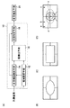
図1(A)に示す赤目検出装置10(以下、検出装置10とする)は、入力された処理対象画像(その画像データ)から特定領域として赤目を検出して、赤目補正手段20に出力するもので、領域検出手段12と、赤目候補検出手段14と、顔検出手段16と、赤目特定手段18とを有して構成される。このような画像検出装置10は、一例として、パーソナルコンピュータ、ワークステーションなどのコンピュータや、DSP(Digital Signal Processor)等を利用して構成される。
なお、検出装置10と赤目補正手段20とは、一体的に構成されていてもよく、あるいは、検出装置10(あるいはさらに、赤目補正手段20)は、色/濃度補正、階調補正、電子変倍処理、シャープネス処理等の各種の画像処理を行う画像処理装置(手段)に組み込まれるものであってもよい。
FIG. 1A conceptually shows, in a block diagram, an example of a red-eye detection apparatus using the specific area detection method and the specific area detection apparatus according to the present invention. The program of the present invention is a program for executing the processing described below.
A red-eye detection device 10 (hereinafter referred to as detection device 10) shown in FIG. 1A detects a red eye as a specific area from an input processing target image (its image data), and outputs it to the red-eye correction means 20. In other words, the image forming apparatus includes an
Note that the
本発明の検出装置10において、赤目検出を行う処理対象画像(以下、対象画像とする)は、カラー画像であれば特に限定はなく、例えば、カメラによって写真フィルムに撮影された画像(画像を撮影された写真フィルムを光電的に読み取って得られた画像データ)や、デジタルカメラで撮影された画像(画像データ)であってもよい。また、対象画像は、撮影された画像そのものではなく、必要に応じて各種の画像処理を施された画像(画像データ)であってもよいのは、もちろんである。
In the
対象画像は、まず、領域検出手段12および赤目候補検出手段14に供給される。
領域設定手段12は、供給された対象画像において、主要部領域と非主要部領域とを設定して、その設定結果(例えば、画素番号や領域を示す座標データ等)を赤目候補検出手段14および顔検出手段16に供給するものである。
The target image is first supplied to the
The
図示例においては、一例として、領域設定手段12は、図1(B)や図1(C)に示すような、領域設定のためのテンプレートを有しており、必要に応じてテンプレート(もしくは対象画像)の拡大/縮小を行って、対象画像にこのテンプレートをあてはめ、画像の中央領域((B)であれば中央の楕円領域、(C)であれば中央の長方形領域)を主要部領域と設定し、それ以外の領域を非主要部領域と設定して、その設定結果を赤目候補検出手段14および顔検出手段16に送る。
なお、テンプレートの拡大/縮小ではなく、想定される対象画像のサイズに応じた複数サイズのテンプレートを有してもよく、また、複数サイズのテンプレートと拡大/縮小とを併用してもよい。
In the illustrated example, as an example, the region setting means 12 has a template for region setting as shown in FIG. 1B or FIG. 1C, and a template (or target) as necessary. The image is enlarged / reduced, and this template is applied to the target image. The central area of the image (the central elliptical area in (B) and the central rectangular area in (C)) is defined as the main area. The other area is set as a non-main part area, and the setting result is sent to the red-eye candidate detection means 14 and the face detection means 16.
Instead of enlarging / reducing the template, a template having a plurality of sizes according to the assumed size of the target image may be provided, or a template having a plurality of sizes and enlarging / reducing may be used in combination.
主要部領域とする画像中央領域の決定方法には、特に限定はなく、検出装置10に要求される適正に応じて、適宜、決定すればよい。例えば、主要部領域が大きくなるほど、赤目検出の処理時間は遅くなるが、画像全体で見た際の赤目検出の精度は高くなるので、検出装置10に要求される処理時間や処理精度に応じて、主要部領域とする画像中央領域を、適宜、決定する方法が例示される。
また、主要部領域とする画像中央領域の大きさが異なるテンプレートを複数用意しておいて選択可能にしてもよく、および/または、所定のテンプレートにおいて、主要部領域とする画像中央領域を任意に設定可能にしてもよい。
There is no particular limitation on the method for determining the image center region as the main region, and it may be determined as appropriate according to the appropriateness required for the
In addition, a plurality of templates having different sizes of the image central area as the main area may be prepared and selectable, and / or the image central area as the main area may be arbitrarily selected in a predetermined template. It may be settable.
本発明において、主要部領域および非主要部領域の設定方法は、このように画像の中央領域と周辺領域とで設定する方法に限定はされず、各種の方法が利用可能である。
例えば、画像解析を行って、焦点(ピント)が合っている領域を主要部領域とし、それ以外の領域を非主要部領域とする方法が例示される。なお、画像中の合焦領域の抽出は、公知の方法で行えばよい。
また、一般的に、ストロボ撮影を含めて、画像中の主要部に相当する領域は、背景領域に比して高輝度になる場合が多い。それを利用して、画像中において閾値を超えた高輝度領域を主要部領域とし、それ以外の領域を非主要部領域としてもよい。あるいは、画像ファイルに記録された各種の情報や、APSであればフィルムに記録された磁気情報から、ストロボのガイドナンバー、照射領域、焦点距離、測離情報を求め、ストロボが照射された領域を主要部領域とし、それ以外のストロボが照射されなかった領域を非主要部領域としてもよい。
さらに、後述する顔検出に対応して、赤目候補検出手段14が検出した赤目候補領域が集中する領域を主要部領域としてもよい。この点に関しては、後に詳述する。
In the present invention, the method for setting the main area and the non-main area is not limited to the method for setting the central area and the peripheral area of the image as described above, and various methods can be used.
For example, a method in which image analysis is performed and an area in focus (focus) is set as a main part area, and other areas are set as non-main part areas is exemplified. In addition, what is necessary is just to perform the extraction of the focusing area | region in an image by a well-known method.
In general, an area corresponding to a main part in an image including flash photography often has higher brightness than a background area. By utilizing this, a high luminance area exceeding a threshold value in the image may be set as a main part area, and the other area may be set as a non-main part area. Alternatively, from various information recorded in the image file or magnetic information recorded on the film in the case of APS, the strobe guide number, irradiation area, focal length, and distance measurement information are obtained, and the area irradiated with the strobe is determined. The main region may be a non-main region that is not irradiated with any other strobe.
Furthermore, an area where the red-eye candidate areas detected by the red-eye candidate detecting means 14 are concentrated may be set as a main area corresponding to face detection described later. This will be described in detail later.
赤目候補検出手段14は、対象画像中から、赤目である可能性のある領域すなわち赤目候補を検出し、赤目候補の位置情報(中心の座標位置情報)、領域情報、個数の情報等を、赤目候補の情報として顔検出手段16および赤目特定手段18に供給するものである。
一例として、図1(D)に示すように、背景に3つの赤ランプを有するシーンで人物を撮影し、この人物に赤目現象が生じた画像(シーン)であれば、赤ランプに対応するa、b、およびc、ならびに、赤目に対応するdおよびeで示す領域を赤目候補として検出し、顔検出手段16および赤目特定手段18に供給する。
The red-eye candidate detection means 14 detects a region that may be a red eye, that is, a red-eye candidate, from the target image, and uses the red-eye candidate position information (center coordinate position information), region information, number information, etc. The information is supplied to the face detection means 16 and the red eye identification means 18 as candidate information.
As an example, as shown in FIG. 1D, if a person is photographed in a scene having three red lamps in the background and a red-eye phenomenon occurs in the person, a corresponding to the red lamp , B, and c, and regions indicated by d and e corresponding to red eyes are detected as red eye candidates and supplied to the face detection means 16 and the red eye identification means 18.
赤目候補の検出方法には、特に限定はなく、公知の各種の方法が利用可能である。
一例として、赤色の色相で、かつ、所定画素数以上が集まっている領域を抽出し、予め多数の赤目の画像サンプルから設定した、赤目度(どの程度赤目らしい色か)および円形度(どの程度丸いか)を用い、赤目度および円形度が閾値を超えた領域を、赤目である可能性を有する赤目候補として検出する方法が例示される。
There are no particular limitations on the method for detecting a red-eye candidate, and various known methods can be used.
As an example, a region with a red hue and a predetermined number of pixels or more is extracted and set in advance from a number of red-eye image samples. A method of detecting a region in which the red-eye degree and the circularity exceed a threshold value as a red-eye candidate having a possibility of being a red-eye is exemplified.
ここで、図示例の検出装置10においては、先に領域設定手段12によって設定された主要部領域と非主要部領域とで、赤目候補検出の条件を変える。
一例として、主要部領域では赤目である可能性が低くても赤目候補として検出し、非主要部では、赤目である可能性が高い領域のみを赤目候補として検出する。具体的には、前述のように、赤目度および円形度が閾値を超えた領域を赤目候補として検出する際には、主要部領域では閾値を低くして赤目候補検出を行う。あるいは逆に、非主要部領域の閾値を高くして赤目候補検出を行ってもよい。従って、例えば、図1(D)に示す例であれば、主要部領域の赤目候補dおよびeは、非主要部領域の赤目候補a〜cよりも低い閾値で検出された赤目候補である。
後述する顔検出手段16では、赤目候補の周辺のみで顔検出を行う。従って、これにより、重要度の低い非主要部領域での顔検出処理を少なくし、すなわち顔検出手段16において行う顔検出処理量を低減して、赤目検出の処理時間を短縮することができる。
Here, in the illustrated
As an example, the main region is detected as a red-eye candidate even if the possibility of red-eye is low, and the non-main region is detected as a red-eye candidate only in a region that is highly likely to be red-eye. Specifically, as described above, when a region where the red-eye degree and the circularity exceed the threshold values is detected as a red-eye candidate, the red-eye candidate detection is performed by lowering the threshold value in the main part region. Alternatively, red-eye candidate detection may be performed by increasing the threshold value of the non-main part region. Therefore, for example, in the example shown in FIG. 1D, the red eye candidates d and e in the main part region are red eye candidates detected at a lower threshold than the red eye candidates a to c in the non-main part region.
The face detection means 16 described later performs face detection only around the red-eye candidate. Accordingly, it is possible to reduce the face detection processing in the non-major part region with low importance, that is, reduce the amount of face detection processing performed in the face detection means 16, and shorten the processing time of red eye detection.
赤目候補検出手段14による赤目候補の検出結果、ならびに、領域設定手段12による主要部領域および非主要部領域の設定結果は、顔検出手段16に送られる。
顔検出手段16は、赤目の検出結果(例えば前記位置情報)を用いて、赤目候補検出手段14が検出した赤目候補を含む周辺において、顔検出を行い、自身を含む領域で顔が検出できた赤目候補の情報、あるいはさらに顔の検出結果を赤目特定手段18に供給するものである。
例えば、図1(D)に示す例であれば、前記a、b、c、d、およびeの各赤目候補に対応して、各赤目候補を含む所定領域において、順次、顔検出を行う。従って、顔領域として例えば点線で囲まれた領域が検出され、これに応じて、顔検出手段16は、赤目候補dおよびeが顔領域に含まれる赤目候補であるとの情報、あるいはさらに、検出した顔領域の情報を赤目特定手段18に供給する。
The detection result of the red eye candidate by the red eye
The face detection means 16 performed face detection around the red eye candidate detected by the red eye candidate detection means 14 using the detection result of the red eye (for example, the position information), and the face was detected in the area including itself. The information of the red eye candidate or the detection result of the face is supplied to the red
For example, in the example shown in FIG. 1D, face detection is sequentially performed in a predetermined region including each red-eye candidate corresponding to each of the red-eye candidates a, b, c, d, and e. Accordingly, for example, an area surrounded by a dotted line is detected as the face area, and in response to this, the face detection means 16 detects that the red-eye candidates d and e are red-eye candidates included in the face area, or further detects The information on the face area thus obtained is supplied to the red-
前述のように、顔検出は、非常に時間のかかる処理であるが、従来の赤目検出では、顔検出を行った後に、検出された顔領域内で赤目検出を行っているため、赤目の存在しない領域でも顔検出を行っており、その結果、顔検出に非常に時間がかかる。
これに対し、本発明においては、このように、赤目候補を検出した後に、この赤目候補を含む所定領域でのみ顔検出を行うことにより、赤目が存在しない領域での無駄な顔検出を無くして、赤目検出において、顔検出にかかる時間を大幅に短縮することができる。
As described above, face detection is a very time-consuming process, but in conventional red-eye detection, red-eye detection is performed within the detected face area after face detection, so the presence of red-eye exists. Face detection is performed even in a region that is not, and as a result, it takes a very long time to detect the face.
In contrast, in the present invention, after detecting a red-eye candidate, face detection is performed only in a predetermined area including the red-eye candidate, thereby eliminating useless face detection in an area where no red-eye exists. In red-eye detection, the time required for face detection can be greatly reduced.
顔検出手段16による顔検出の方法には、特に限定はなく、公知の各種の方法が利用可能である。 There is no particular limitation on the method of face detection by the face detection means 16, and various known methods can be used.
一例として、多数の顔の画像サンプルから予め作成した平均的な顔画像いわゆる顔のテンプレート(以下、顔テンプレートとする)を用いて、顔検出を行う方法が例示される。
この方法では、一例として、縦位置(縦撮影)/横位置(横撮影)などの撮影時のカメラの向きに応じて、図2(A)に示すように顔テンプレート(もしくは対象画像)を天地および左右方向に回転(画像面において0°→90°→180°→270°と回転)して顔の向きを変え、かつ、画像中の顔のサイズ(解像度)に応じて、図2(B)に示すような顔テンプレート(同前)の顔サイズの変更(拡大/縮小=解像度変換)を行って、各種の顔の向きおよび顔サイズの組み合わせの顔テンプレートと、画像中の顔候補領域とのマッチング(一致度の確認)を、順次、行って、顔検出を行う。
なお、顔テンプレートの回転および拡大/縮小に変えて、回転した顔テンプレートや拡大/縮小した顔テンプレートを予め作成しておいて、これを用いてマッチングを行ってもよい。また、顔候補領域野検出は、例えば、肌色抽出や輪郭抽出等の手段で行えばよい。
As an example, a method of performing face detection using an average face image so-called face template (hereinafter referred to as a face template) created in advance from a large number of face image samples is exemplified.
In this method, as an example, a face template (or target image) is displayed on the top and bottom as shown in FIG. 2A according to the orientation of the camera at the time of shooting such as vertical position (vertical shooting) / horizontal position (horizontal shooting). The image is rotated in the left-right direction (rotated as 0 ° → 90 ° → 180 ° → 270 ° on the image plane) to change the face direction, and in accordance with the size (resolution) of the face in the image, FIG. ), The face size of the face template (same as above) is changed (enlargement / reduction = resolution conversion), a face template of a combination of various face orientations and face sizes, a face candidate area in the image, The face detection is performed by sequentially performing matching (confirmation of matching).
Instead of rotating and enlarging / reducing the face template, a rotated face template or an enlarged / reduced face template may be created in advance, and matching may be performed using the template. The face candidate area detection may be performed by means such as skin color extraction or contour extraction.
また、学習手法を使用した顔検出も好適に例示される。
この方法では、多数の顔画像と非顔画像とを用意して、それぞれの特徴量の抽出を行って、その結果から、適宜選択した学習手法(例えば、Boostong等)を利用して、顔か非顔かを分離する関数や閾値を算出する、事前学習を行う。顔検出を行う際には、対象画像に対して、事前学習と同様にして特徴量の抽出を行って、事前学習で得られた関数や閾値を用いて顔か非顔かを判別して、顔検出を行う。
Moreover, the face detection using a learning method is also illustrated suitably.
In this method, a large number of face images and non-face images are prepared, the respective feature amounts are extracted, and the results are extracted from the results using an appropriately selected learning method (for example, Boostong or the like). Pre-learning is performed to calculate a function for separating non-face and a threshold value. When performing face detection, the feature amount is extracted from the target image in the same manner as in the pre-learning, and it is determined whether it is a face or a non-face using the function and threshold obtained in the pre-learning, Perform face detection.
また、特開平8−184925号や特開平9−138471号の各公報に開示される、エッジ(輪郭)抽出やエッジ方向の抽出による形状認識、肌色抽出や黒抽出等の色抽出を組み合わせた方法や、前記特許文献1〜3において、顔テンプレートを用いたマッチング以外の顔候補の検出方法として例示されている各方法も、利用可能である。
Also, methods disclosed in Japanese Patent Laid-Open Nos. 8-184925 and 9-138471, which combine color extraction such as shape recognition by edge (contour) extraction and edge direction extraction, skin color extraction, and black extraction. In addition, in the above-described
ここで、本発明においては、顔検出手段16においても、領域設定手段12が設定した主要部領域と非主要部領域とで、異なる条件で顔検出を行う。例えば、図1(D)の例であれば、主要部領域に位置する赤目候補dおよびeに対しては、処理時間がかかっても誤検出や見落としの無い高精度な顔検出を行い、非主要部領域に位置するa〜cの赤目候補では、高速で処理が行えるように顔検出を行う。
もしくは、顔検出は主要部領域のみで行い、非主要部領域での顔検出は行わない方法も利用可能である。
Here, in the present invention, the
Alternatively, it is possible to use a method in which face detection is performed only in the main part region and face detection is not performed in the non-main part region.
このように、主要部領域では高精度な顔検出を行い、非主要部領域では高速での顔検出を行う、もしくは非部主要部領域では顔検出を行わないことにより、前述の主要部領域と非主要部領域とで条件を変えた赤目候補検出の効果と相俟って、非常に高速に、かつ、重要である主要部領域では高精度な赤目検出を行うことが可能となる。
なお、この赤目検出では、非主要部領域とされた周辺領域では赤目を適正に検出できない可能性があるが、通常、主要な被写体は画像の中央に存在しているので、画像品質的には問題となることは少ない。
In this way, by performing high-precision face detection in the main part area and performing high-speed face detection in the non-main part area, or by not performing face detection in the non-part main part area, Combined with the effect of red-eye candidate detection in which the conditions are changed in the non-main part region, it is possible to detect red eyes with high accuracy in the main part region which is very fast and important.
Note that with this red-eye detection, there is a possibility that the red-eye cannot be properly detected in the peripheral area set as the non-main part area.However, since the main subject usually exists in the center of the image, the image quality is There are few problems.
主要部領域と非主要部領域における顔検出の条件の違いには、特に限定はなく、各種の態様が利用可能である。
例えば、非主要部領域においては、肌色度、円形度、顔テンプレートとの一致度などにおいて、顔では無いと判断する閾値を高くする方法(あるいは、主要部領域では閾値を低くする方法)が例示される。この方法によれば、主要部領域においては高精度に顔抽出を行い、非主要部領域での顔検出時間を短縮することができる。
また、前述の顔テンプレートを用いたマッチングによる顔検出等であれば、主要部領域では全ての顔サイズに対応した顔検出を行い、非主要部領域では、例えば、標準の顔サイズのみの顔検出を行う、所定の顔サイズ以上のみの顔検出を行う等、所定の顔サイズのみでしか顔検出を行わない方法も好適である。
There is no particular limitation on the difference in face detection conditions between the main part region and the non-main part region, and various modes can be used.
For example, in a non-main part region, a method of increasing the threshold value for determining that the face is not a face (or a method of reducing the threshold value in the main part region) in skin chromaticity, circularity, matching degree with a face template, etc. Is done. According to this method, face extraction can be performed with high accuracy in the main area, and the face detection time in the non-main area can be shortened.
In addition, in the case of face detection by matching using the face template described above, face detection corresponding to all face sizes is performed in the main area, and for example, face detection of only the standard face size is performed in the non-main area. It is also preferable to perform face detection only with a predetermined face size, such as performing face detection only for a predetermined face size or more.
また、主要部領域と非主要部領域とで、顔検出の方法を変えるのも好適である。
例えば、主要部領域では、高精度な顔検出を行うことができる前記顔テンプレートを用いたマッチングによる顔検出や、学習手法を利用した顔検出を行い、非主要部領域では、前記特開平8−184925号や特開平9−138471号の各公報等に開示される、短時間での処理が可能な肌色抽出、エッジ抽出による形状認識、肌色抽出等による顔検出を行う方法も例示される。あるいは、非主要部領域では、エッジ抽出による形状認識のみでの顔検出や、肌色検出のみでの顔検出を行うようにしてもよい。
It is also preferable to change the face detection method between the main area and the non-main area.
For example, face detection by matching using the face template capable of performing highly accurate face detection or face detection using a learning method is performed in the main part area, and in the non-main part area, Examples of the method of performing face detection by skin color extraction that can be processed in a short time, shape recognition by edge extraction, skin color extraction, and the like, which are disclosed in Japanese Patent Nos. 184925 and JP-A-9-138471. Alternatively, in the non-main part region, face detection only by shape recognition by edge extraction or face detection only by skin color detection may be performed.
前述のように、赤目候補検出手段14による赤目候補の検出結果、および、顔検出手段16で顔が検出できた赤目候補は、赤目特定手段18に供給される。
赤目特定手段18は、これらの情報を用いて、周囲に顔が検出できた赤目候補を赤目と特定し、対象画像における赤目の検出結果として、各赤目の位置情報および領域の情報、赤目の個数の情報等を赤目補正手段20に供給する。
As described above, the detection result of the red eye candidate by the red eye
The red-eye specifying means 18 uses these pieces of information to identify red-eye candidates whose faces can be detected around as red-eye, and as red-eye detection results in the target image, the position information of each red-eye, region information, and the number of red-eye Is supplied to the red-eye correction means 20.
赤目補正手段20は、赤目特定手段18から供給された赤目の検出結果に応じて、対象画像の赤目領域の画像処理を行って、対象画像の赤目補正をなう。
赤目補正の方法には、特に限定はなく、公知の方法が各種利用可能である。例えば、赤目や赤目周囲(顔の周囲を含んでもよい)の画像特徴量等に応じて赤目領域の彩度、明度、色相等をコントロールして赤目を補正する補正処理や、単純に赤目領域の色を黒に変換する補正処理等が例示される。
The red-
The red-eye correction method is not particularly limited, and various known methods can be used. For example, correction processing that corrects red eye by controlling the saturation, brightness, hue, etc. of the red eye region according to the image feature amount of the red eye and the surroundings of the red eye (may include the periphery of the face) The correction process etc. which convert a color into black are illustrated.
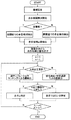
以下、図3のフローチャートを参照して、この赤目検出について詳細に説明することにより、本発明を、より詳細に説明する。 Hereinafter, the present invention will be described in more detail by describing this red-eye detection in detail with reference to the flowchart of FIG.
対象画像が供給され、赤目検出が開始されると、まず、領域設定手段12が前述のように画像のどの領域が主要部領域で、どの領域が非主要部領域かを設定し、赤目候補検出手段14および顔検出手段16に設定結果を供給する。
When the target image is supplied and red-eye detection is started, the region setting means 12 first sets which region of the image is the main region and which region is the non-main region as described above, and detects the red eye candidate. Setting results are supplied to the
。
次いで、赤目候補検出手段14による赤目候補の検出が開始される。赤目候補検出は、領域設定手段12による領域設定に応じて、主要部領域では前述のように低閾値での赤目候補検出を行って、赤目の可能性が低い領域でも赤目候補領域として検出し、非主要部領域では、高閾値での赤目候補検出を行って、赤目の可能性が高い領域のみを赤目候補領域として検出する。
全部でm個の赤目候補が検出できたとして、赤目候補検出手段14は、画像の中央に近い赤目候補領域から、順次、番号付け(ナンバリング)を行い、赤目候補検出結果を顔検出手段16および赤目特定手段18に送る。
.
Next, detection of red-eye candidates by the red-eye candidate detection means 14 is started. According to the area setting by the area setting means 12, the red eye candidate detection is performed by detecting a red eye candidate at a low threshold value in the main area as described above, and detecting a red eye candidate area even in a low possibility of red eye, In the non-main area, red-eye candidate detection with a high threshold is performed, and only areas with a high possibility of red-eye are detected as red-eye candidate areas.
Assuming that m red-eye candidates have been detected in total, the red-eye candidate detection means 14 sequentially numbers (numbers) the red-eye candidate areas close to the center of the image, and the red-eye candidate detection results are sent to the face detection means 16 and It is sent to the red
赤目候補の検出結果を受けた顔検出手段16は、先の領域設定手段12による領域設定に応じて、最初(n=1)の赤目候補(A点)が主要部領域か非主要部領域かを判定し、一例として、主要部領域である場合には、高精度な顔検出が可能な前記顔テンプレートを用いたマッチングによる顔検出を行い、非主要部領域である場合には、高速処理が可能な肌色抽出およびエッジ抽出による形状認識での顔検出を行う。
A点で顔検出を行った顔検出手段16は、A点で顔が検出できたか否かの情報を赤目特定手段18に送る。
Upon receiving the detection result of the red eye candidate, the
The face detection means 16 that has detected the face at the point A sends information to the red-eye identification means 18 as to whether or not a face has been detected at the point A.
赤目特定手段18は、顔検出結果に応じて、A点で顔が検出できた場合には、この赤目候補を赤目と特定し、A点で顔が検出できなかった場合には、この赤目候補は赤目ではないと特定する。
If the face is detected at point A according to the face detection result, the red-
A点が赤目であるか否かの特定を終了したら、A点をn+1とし、A>mであれば次のA点(赤目候補)について、顔検出を行い、以下同様にして、これ以降の赤目候補における顔検出を、順次、行い、A>mとなった時点、すなわち、全ての赤目候補についての顔検出を終了したら、赤目検出を終了する。 When the identification of whether or not the point A has red eyes is finished, the point A is set to n + 1. If A> m, face detection is performed for the next point A (red-eye candidate), and so on. Face detection in the red-eye candidates is sequentially performed, and when A> m is satisfied, that is, when face detection has been completed for all red-eye candidates, the red-eye detection is ended.
以上の例では、赤目候補検出手段14と顔検出手段16(赤目候補検出と顔検出)は、同じ主要部領域および非主要部領域に応じて赤目検出および顔検出を行っている。しかしながら、本発明は、これに限定はされず、赤目候補検出手段14と顔検出手段16とで、位置や大きさが異なる主要部領域および非主要部領域を設定してもよい。
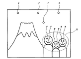
例えば、赤目候補手段14では、図1(B)や(C)に示されるテンプレートを用いて画像中央を主要部領域として赤目候補検出を行い、あるいは、主要部を設定せずに全域で同条件で赤目候補検出を行う。次いで、赤目候補の検出結果に応じて、図4に示すように、赤目候補rが集中している領域を含む周辺領域xを主要部領域、それ以外を非主要部領域として、顔検出手段16で顔検出を行ってもよい。
なお、この際には、例えば、赤目候補検出手段14が赤目候補検出結果を領域設定手段12供給し、領域設定手段12において、赤目候補が集中している領域を含む領域を含む円形や楕円計や矩形の領域を主要部領域として設定すればよい。
In the above example, the red-eye candidate detection means 14 and the face detection means 16 (red-eye candidate detection and face detection) perform red-eye detection and face detection according to the same main area and non-main area. However, the present invention is not limited to this, and the main part region and the non-main part region having different positions and sizes may be set in the red-eye
For example, the red-eye candidate means 14 detects a red-eye candidate using the template shown in FIGS. 1B and 1C as the main area of the center of the image, or the same condition throughout the entire area without setting the main part. To detect red-eye candidates. Then, according to the detection result of the red eye candidate, as shown in FIG. 4, the face detection means 16 uses the peripheral region x including the region where the red eye candidates r are concentrated as the main region and the other regions as the non-main region. The face may be detected by using.
In this case, for example, the red eye
また、赤目候補検出手段14では画像全体で同条件で赤目候補検出を行い(すなわち主要部領域の設定をしない)、顔検出手段16では設定した主要部領域と非主要部領域とで顔検出の条件を変えてもよく、あるいは逆に、赤目候補検出手段14では設定した主要部領域と非主要部領域とで赤目候補検出の条件を変え、顔検出手段16では、検出された赤目候補に対して領域によらず同条件で顔検出を行ってもよい。
Further, the red eye candidate detection means 14 performs red eye candidate detection under the same conditions for the entire image (that is, the main area is not set), and the face detection means 16 performs face detection using the set main area and non-main area. The condition may be changed, or conversely, the red-eye
以上、本発明の特定領域検出方法、特定領域検出装置、およびプログラムについて詳細に説明したが、本発明は上記実施例に限定はされず、本発明の要旨を逸脱しない範囲において、各種の改良や変更を行ってもよいのは、もちろんである。 The specific area detection method, the specific area detection apparatus, and the program of the present invention have been described in detail above. However, the present invention is not limited to the above-described embodiments, and various improvements and modifications can be made without departing from the spirit of the present invention. Of course, changes may be made.
例えば、以上の例は、本発明の検出方法を赤目検出に利用した例であるが、本発明は、これに限定はされず、目、目じり、眉毛、口、鼻、眼鏡、ニキビ、ホクロ、しわ等、画像中の顔領域に存在し得る各種の物を特定領域として、画像中から例えばニキビ候補を検出して、その周辺で顔検出を行い、顔が検出できたニキビ候補をニキビと特定してもよい。
この際における特定領域候補の検出方法は、例えば、検出対象となる特定領域に固有の色や形状を有する領域を画像中から検出する方法が例示される。また、顔検出と同様に、検出対象となる特定領域の多数の画像サンプルから、予め作成した平均的な特定領域の画像(テンプレート)を用いて、マッチングを行う方法も好適である。例えば、多数の目じりの画像サンプルから予め作成した平均的な目じりの画像すなわち目じりのテンプレートを用い、マッチングを行って目じりを検出する方法が例示される。
For example, the above example is an example in which the detection method of the present invention is used for red eye detection, but the present invention is not limited to this, and the eyes, eyes, eyebrows, mouth, nose, glasses, acne, mole, For example, a candidate for acne is detected in the image from various objects that may exist in the face area in the image, such as wrinkles, and the face is detected in the vicinity, and the acne candidate in which the face can be detected is identified as acne. May be.
The specific area candidate detection method in this case is exemplified by a method of detecting an area having a color or shape unique to the specific area to be detected from the image. Similarly to face detection, a method of performing matching using an image (template) of an average specific area created in advance from a large number of image samples of a specific area to be detected is also suitable. For example, a method of detecting a heading by performing matching using an average heading image prepared in advance from a large number of heading image samples, that is, a heading template, is exemplified.
10 (赤目)検出装置
12 領域設定手段
14 赤目候補検出手段
16 顔検出手段
18 赤目特定手段
20 赤目補正手段
DESCRIPTION OF SYMBOLS 10 (Red eye)
Claims (8)
前記画像の主要部領域と非主要部領域とで、前記特定領域候補検出および顔検出の少なくとも一方における検出条件を変更することを特徴とする特定領域検出方法。 A specific area candidate in the image is detected, and then face detection is performed in the area including the detected specific area candidate, and the specific area candidate included in the area where the face can be detected is specified as the specific area to be detected. ,
A specific area detection method, wherein a detection condition in at least one of the specific area candidate detection and face detection is changed between a main area and a non-main area of the image.
かつ、候補検出手段および前記顔検出手段の少なくとも一方は、画像の主要部領域と非主要部領域とで、検出対象の検出条件を変更することを特徴とする特定領域検出装置。 A candidate detection unit that detects a specific area candidate from the image of the supplied image data, a face detection unit that performs face detection in an area including the specific area candidate detected by the candidate detection unit, and a face detected by the face detection unit A specifying means for specifying a specific area candidate included in the detected area as a specific area to be detected;
In addition, at least one of the candidate detection unit and the face detection unit changes a detection condition of a detection target between a main part region and a non-main part region of an image.
かつ、前記候補検出手段および顔検出手段の少なくとも一方においては、主要部領域と非主要部領域とで、検出対象の検出条件を変更することを特徴とするプログラム。 Candidate detection means for detecting a specific area candidate from the supplied image data image, face detection means for detecting a face in an area including the specific area candidate detected by the candidate detection means, and a face detected by the face detection means A specific means for specifying a specific area candidate included in the detected area as a specific area to be detected;
In addition, in at least one of the candidate detection unit and the face detection unit, a detection target detection condition is changed between a main part region and a non-main part region.
Priority Applications (2)
| Application Number | Priority Date | Filing Date | Title |
|---|---|---|---|
| JP2004105711A JP4320272B2 (en) | 2004-03-31 | 2004-03-31 | Specific area detection method, specific area detection apparatus, and program |
| US11/094,239 US7613332B2 (en) | 2004-03-31 | 2005-03-31 | Particular-region detection method and apparatus, and program therefor |
Applications Claiming Priority (1)
| Application Number | Priority Date | Filing Date | Title |
|---|---|---|---|
| JP2004105711A JP4320272B2 (en) | 2004-03-31 | 2004-03-31 | Specific area detection method, specific area detection apparatus, and program |
Publications (2)
| Publication Number | Publication Date |
|---|---|
| JP2005293096A true JP2005293096A (en) | 2005-10-20 |
| JP4320272B2 JP4320272B2 (en) | 2009-08-26 |
Family
ID=35054328
Family Applications (1)
| Application Number | Title | Priority Date | Filing Date |
|---|---|---|---|
| JP2004105711A Expired - Fee Related JP4320272B2 (en) | 2004-03-31 | 2004-03-31 | Specific area detection method, specific area detection apparatus, and program |
Country Status (2)
| Country | Link |
|---|---|
| US (1) | US7613332B2 (en) |
| JP (1) | JP4320272B2 (en) |
Cited By (7)
| Publication number | Priority date | Publication date | Assignee | Title |
|---|---|---|---|---|
| JP2009237661A (en) * | 2008-03-26 | 2009-10-15 | Seiko Epson Corp | Image processor, image processing method and computer program for image processing |
| JP2009239871A (en) * | 2008-03-28 | 2009-10-15 | Canon Inc | Method of detecting object and its device |
| JP2010003165A (en) * | 2008-06-20 | 2010-01-07 | Canon Inc | Image processor and image processing method, computer program, and recording medium |
| JP2011511358A (en) * | 2008-02-01 | 2011-04-07 | ヒューレット−パッカード デベロップメント カンパニー エル.ピー. | Automatic red eye detection |
| JP2012230501A (en) * | 2011-04-25 | 2012-11-22 | Canon Inc | Image processing apparatus and image processing method |
| JP2014016821A (en) * | 2012-07-09 | 2014-01-30 | Canon Inc | Image processing apparatus, image processing method, and program |
| JP2014232370A (en) * | 2013-05-28 | 2014-12-11 | 東芝テック株式会社 | Recognition dictionary creation device and recognition dictionary creation program |
Families Citing this family (56)
| Publication number | Priority date | Publication date | Assignee | Title |
|---|---|---|---|---|
| US7042505B1 (en) | 1997-10-09 | 2006-05-09 | Fotonation Ireland Ltd. | Red-eye filter method and apparatus |
| US7630006B2 (en) * | 1997-10-09 | 2009-12-08 | Fotonation Ireland Limited | Detecting red eye filter and apparatus using meta-data |
| US7738015B2 (en) | 1997-10-09 | 2010-06-15 | Fotonation Vision Limited | Red-eye filter method and apparatus |
| US7574016B2 (en) | 2003-06-26 | 2009-08-11 | Fotonation Vision Limited | Digital image processing using face detection information |
| US8254674B2 (en) | 2004-10-28 | 2012-08-28 | DigitalOptics Corporation Europe Limited | Analyzing partial face regions for red-eye detection in acquired digital images |
| US7336821B2 (en) | 2006-02-14 | 2008-02-26 | Fotonation Vision Limited | Automatic detection and correction of non-red eye flash defects |
| US8170294B2 (en) * | 2006-11-10 | 2012-05-01 | DigitalOptics Corporation Europe Limited | Method of detecting redeye in a digital image |
| US7689009B2 (en) | 2005-11-18 | 2010-03-30 | Fotonation Vision Ltd. | Two stage detection for photographic eye artifacts |
| US8036458B2 (en) | 2007-11-08 | 2011-10-11 | DigitalOptics Corporation Europe Limited | Detecting redeye defects in digital images |
| US7920723B2 (en) | 2005-11-18 | 2011-04-05 | Tessera Technologies Ireland Limited | Two stage detection for photographic eye artifacts |
| US7792970B2 (en) | 2005-06-17 | 2010-09-07 | Fotonation Vision Limited | Method for establishing a paired connection between media devices |
| US7970182B2 (en) | 2005-11-18 | 2011-06-28 | Tessera Technologies Ireland Limited | Two stage detection for photographic eye artifacts |
| US9412007B2 (en) | 2003-08-05 | 2016-08-09 | Fotonation Limited | Partial face detector red-eye filter method and apparatus |
| US8520093B2 (en) | 2003-08-05 | 2013-08-27 | DigitalOptics Corporation Europe Limited | Face tracker and partial face tracker for red-eye filter method and apparatus |
| US8320641B2 (en) | 2004-10-28 | 2012-11-27 | DigitalOptics Corporation Europe Limited | Method and apparatus for red-eye detection using preview or other reference images |
| US7869630B2 (en) * | 2005-03-29 | 2011-01-11 | Seiko Epson Corporation | Apparatus and method for processing image |
| US7599577B2 (en) | 2005-11-18 | 2009-10-06 | Fotonation Vision Limited | Method and apparatus of correcting hybrid flash artifacts in digital images |
| JP4549997B2 (en) * | 2006-03-30 | 2010-09-22 | 富士フイルム株式会社 | Red-eye detection device, red-eye detection method, and red-eye detection program |
| JP4910462B2 (en) * | 2006-04-14 | 2012-04-04 | 株式会社ニコン | camera |
| IES20060564A2 (en) * | 2006-05-03 | 2006-11-01 | Fotonation Vision Ltd | Improved foreground / background separation |
| US7965875B2 (en) | 2006-06-12 | 2011-06-21 | Tessera Technologies Ireland Limited | Advances in extending the AAM techniques from grayscale to color images |
| US8055067B2 (en) | 2007-01-18 | 2011-11-08 | DigitalOptics Corporation Europe Limited | Color segmentation |
| EP2145288A4 (en) | 2007-03-05 | 2013-09-04 | Digitaloptics Corp Europe Ltd | Red eye false positive filtering using face location and orientation |
| EP2015568B1 (en) * | 2007-06-14 | 2019-02-13 | FUJIFILM Corporation | Digital image pickup apparatus |
| US8094343B2 (en) | 2007-08-31 | 2012-01-10 | Brother Kogyo Kabushiki Kaisha | Image processor |
| JP4442664B2 (en) * | 2007-08-31 | 2010-03-31 | ブラザー工業株式会社 | Image processing apparatus, image processing method, and image processing program |
| JP4433017B2 (en) * | 2007-08-31 | 2010-03-17 | ブラザー工業株式会社 | Image processing apparatus and image processing program |
| US8174731B2 (en) | 2007-08-31 | 2012-05-08 | Brother Kogyo Kabushiki Kaisha | Image processing device outputting image for selecting sample image for image correction |
| JP4793356B2 (en) * | 2007-08-31 | 2011-10-12 | ブラザー工業株式会社 | Image processing apparatus and image processing program |
| US8159716B2 (en) | 2007-08-31 | 2012-04-17 | Brother Kogyo Kabushiki Kaisha | Image processing device performing image correction by using a plurality of sample images |
| US8503818B2 (en) * | 2007-09-25 | 2013-08-06 | DigitalOptics Corporation Europe Limited | Eye defect detection in international standards organization images |
| CN104866553A (en) | 2007-12-31 | 2015-08-26 | 应用识别公司 | Method, system, and computer program for identification and sharing of digital images with face signatures |
| US9639740B2 (en) | 2007-12-31 | 2017-05-02 | Applied Recognition Inc. | Face detection and recognition |
| US9721148B2 (en) | 2007-12-31 | 2017-08-01 | Applied Recognition Inc. | Face detection and recognition |
| JP5089405B2 (en) * | 2008-01-17 | 2012-12-05 | キヤノン株式会社 | Image processing apparatus, image processing method, and imaging apparatus |
| US8212864B2 (en) | 2008-01-30 | 2012-07-03 | DigitalOptics Corporation Europe Limited | Methods and apparatuses for using image acquisition data to detect and correct image defects |
| US8081254B2 (en) | 2008-08-14 | 2011-12-20 | DigitalOptics Corporation Europe Limited | In-camera based method of detecting defect eye with high accuracy |
| US8170332B2 (en) * | 2009-10-07 | 2012-05-01 | Seiko Epson Corporation | Automatic red-eye object classification in digital images using a boosting-based framework |
| US8929614B2 (en) * | 2009-10-19 | 2015-01-06 | Hewlett-Packard Development Company, L.P. | Red eye detection aided by face detection |
| JP5924977B2 (en) * | 2011-03-18 | 2016-05-25 | キヤノン株式会社 | Image processing apparatus and image processing method |
| US8532566B2 (en) | 2011-06-08 | 2013-09-10 | Andrew Llc | System and method for reducing desensitization of a base station transceiver for mobile wireless repeater systems |
| US9552376B2 (en) | 2011-06-09 | 2017-01-24 | MemoryWeb, LLC | Method and apparatus for managing digital files |
| US9111130B2 (en) * | 2011-07-08 | 2015-08-18 | Microsoft Technology Licensing, Llc | Facilitating face detection with user input |
| US8548207B2 (en) | 2011-08-15 | 2013-10-01 | Daon Holdings Limited | Method of host-directed illumination and system for conducting host-directed illumination |
| JP2013045316A (en) * | 2011-08-25 | 2013-03-04 | Sanyo Electric Co Ltd | Image processing device and image processing method |
| US9202105B1 (en) | 2012-01-13 | 2015-12-01 | Amazon Technologies, Inc. | Image analysis for user authentication |
| JP6098133B2 (en) * | 2012-11-21 | 2017-03-22 | カシオ計算機株式会社 | Face component extraction device, face component extraction method and program |
| US10698995B2 (en) | 2014-08-28 | 2020-06-30 | Facetec, Inc. | Method to verify identity using a previously collected biometric image/data |
| US11256792B2 (en) | 2014-08-28 | 2022-02-22 | Facetec, Inc. | Method and apparatus for creation and use of digital identification |
| US10614204B2 (en) | 2014-08-28 | 2020-04-07 | Facetec, Inc. | Facial recognition authentication system including path parameters |
| CA3186147A1 (en) | 2014-08-28 | 2016-02-28 | Kevin Alan Tussy | Facial recognition authentication system including path parameters |
| US10803160B2 (en) | 2014-08-28 | 2020-10-13 | Facetec, Inc. | Method to verify and identify blockchain with user question data |
| US10915618B2 (en) | 2014-08-28 | 2021-02-09 | Facetec, Inc. | Method to add remotely collected biometric images / templates to a database record of personal information |
| USD987653S1 (en) | 2016-04-26 | 2023-05-30 | Facetec, Inc. | Display screen or portion thereof with graphical user interface |
| US10936178B2 (en) | 2019-01-07 | 2021-03-02 | MemoryWeb, LLC | Systems and methods for analyzing and organizing digital photos and videos |
| CN113449542B (en) * | 2020-03-24 | 2023-04-07 | 浙江宇视科技有限公司 | Face-changing identification method, device, equipment and medium |
Family Cites Families (12)
| Publication number | Priority date | Publication date | Assignee | Title |
|---|---|---|---|---|
| US5629752A (en) | 1994-10-28 | 1997-05-13 | Fuji Photo Film Co., Ltd. | Method of determining an exposure amount using optical recognition of facial features |
| JP3576654B2 (en) | 1994-10-31 | 2004-10-13 | 富士写真フイルム株式会社 | Exposure determination method, figure extraction method, and face area determination method |
| JPH09138471A (en) | 1995-09-13 | 1997-05-27 | Fuji Photo Film Co Ltd | Specified shape area extracting method, specified area extracting method and copy condition deciding method |
| JP3506958B2 (en) | 1998-09-10 | 2004-03-15 | 富士写真フイルム株式会社 | Image processing method, image processing apparatus, and recording medium |
| US6445819B1 (en) * | 1998-09-10 | 2002-09-03 | Fuji Photo Film Co., Ltd. | Image processing method, image processing device, and recording medium |
| JP4153108B2 (en) | 1998-10-29 | 2008-09-17 | 富士フイルム株式会社 | Image processing method, image processing apparatus, and recording medium |
| JP2000148980A (en) | 1998-11-12 | 2000-05-30 | Fuji Photo Film Co Ltd | Image processing method, image processor and recording medium |
| JP4526639B2 (en) * | 2000-03-02 | 2010-08-18 | 本田技研工業株式会社 | Face recognition apparatus and method |
| EP1288858A1 (en) * | 2001-09-03 | 2003-03-05 | Agfa-Gevaert AG | Method for automatically detecting red-eye defects in photographic image data |
| KR100455294B1 (en) * | 2002-12-06 | 2004-11-06 | 삼성전자주식회사 | Method for detecting user and detecting motion, and apparatus for detecting user within security system |
| US7116820B2 (en) | 2003-04-28 | 2006-10-03 | Hewlett-Packard Development Company, Lp. | Detecting and correcting red-eye in a digital image |
| US7343028B2 (en) * | 2003-05-19 | 2008-03-11 | Fujifilm Corporation | Method and apparatus for red-eye detection |
-
2004
- 2004-03-31 JP JP2004105711A patent/JP4320272B2/en not_active Expired - Fee Related
-
2005
- 2005-03-31 US US11/094,239 patent/US7613332B2/en not_active Expired - Fee Related
Cited By (8)
| Publication number | Priority date | Publication date | Assignee | Title |
|---|---|---|---|---|
| JP2011511358A (en) * | 2008-02-01 | 2011-04-07 | ヒューレット−パッカード デベロップメント カンパニー エル.ピー. | Automatic red eye detection |
| JP2009237661A (en) * | 2008-03-26 | 2009-10-15 | Seiko Epson Corp | Image processor, image processing method and computer program for image processing |
| JP2009239871A (en) * | 2008-03-28 | 2009-10-15 | Canon Inc | Method of detecting object and its device |
| JP2010003165A (en) * | 2008-06-20 | 2010-01-07 | Canon Inc | Image processor and image processing method, computer program, and recording medium |
| JP2012230501A (en) * | 2011-04-25 | 2012-11-22 | Canon Inc | Image processing apparatus and image processing method |
| JP2014016821A (en) * | 2012-07-09 | 2014-01-30 | Canon Inc | Image processing apparatus, image processing method, and program |
| US9501688B2 (en) | 2012-07-09 | 2016-11-22 | Canon Kabushiki Kaisha | Apparatus, processing method and storage medium storing program |
| JP2014232370A (en) * | 2013-05-28 | 2014-12-11 | 東芝テック株式会社 | Recognition dictionary creation device and recognition dictionary creation program |
Also Published As
| Publication number | Publication date |
|---|---|
| US7613332B2 (en) | 2009-11-03 |
| JP4320272B2 (en) | 2009-08-26 |
| US20050220347A1 (en) | 2005-10-06 |
Similar Documents
| Publication | Publication Date | Title |
|---|---|---|
| JP4320272B2 (en) | Specific area detection method, specific area detection apparatus, and program | |
| JP4373828B2 (en) | Specific area detection method, specific area detection apparatus, and program | |
| US7620242B2 (en) | Particular-region detection method and apparatus, and program therefor | |
| US20050276481A1 (en) | Particular-region detection method and apparatus, and program therefor | |
| US8391595B2 (en) | Image processing method and image processing apparatus | |
| US8184870B2 (en) | Apparatus, method, and program for discriminating subjects | |
| JP2005092759A (en) | Image processing device and method, red-eye detection method, and program | |
| US20070071347A1 (en) | Image processing method, image processing apparatus, and computer-readable recording medium storing image processing program | |
| US7868915B2 (en) | Photographing apparatus, method and computer program product | |
| JP2007066199A (en) | Image processor and image processing method | |
| JP2003344021A (en) | Method for calculating dimension of human face in image and method for detecting face | |
| JP2009110486A (en) | Unit, method and program for image processing, imaging unit, and control method for imaging unit | |
| JP2005322220A (en) | Particular region detecting method, particular region detecting apparatus, and program therefor | |
| US10455163B2 (en) | Image processing apparatus that generates a combined image, control method, and storage medium | |
| JP2011081803A (en) | Red-eye object classification candidate, computer-readable medium, and image processing apparatus | |
| JP2007094840A (en) | Image processing device and image processing method | |
| JP2005286830A (en) | Image processing method, image processing apparatus, and program | |
| JP2005196385A (en) | Image processing apparatus, image processing method and digital camera | |
| US20050094894A1 (en) | Image processing device, image processing method, and program therefor | |
| JP2005202477A (en) | Method for deciding top-and-bottom direction of face image and image recording device and image reproducing device | |
| JP2004145287A (en) | Red-eye effect compensating method, picture processing method, printing method and printer | |
| JP2006344166A (en) | Image processing device and method | |
| JP2006018805A (en) | Particular region detection method, particular region detection apparatus and program | |
| JP2007200068A (en) | Photographic image processing method and device thereof | |
| JP2010074312A (en) | Image processing apparatus and method, and program |
Legal Events
| Date | Code | Title | Description |
|---|---|---|---|
| A711 | Notification of change in applicant |
Free format text: JAPANESE INTERMEDIATE CODE: A712 Effective date: 20061208 |
|
| A621 | Written request for application examination |
Free format text: JAPANESE INTERMEDIATE CODE: A621 Effective date: 20070329 |
|
| RD04 | Notification of resignation of power of attorney |
Free format text: JAPANESE INTERMEDIATE CODE: A7424 Effective date: 20080711 |
|
| A977 | Report on retrieval |
Free format text: JAPANESE INTERMEDIATE CODE: A971007 Effective date: 20081203 |
|
| A131 | Notification of reasons for refusal |
Free format text: JAPANESE INTERMEDIATE CODE: A131 Effective date: 20081224 |
|
| A521 | Request for written amendment filed |
Free format text: JAPANESE INTERMEDIATE CODE: A523 Effective date: 20090223 |
|
| A131 | Notification of reasons for refusal |
Free format text: JAPANESE INTERMEDIATE CODE: A131 Effective date: 20090317 |
|
| A521 | Request for written amendment filed |
Free format text: JAPANESE INTERMEDIATE CODE: A523 Effective date: 20090430 |
|
| TRDD | Decision of grant or rejection written | ||
| A01 | Written decision to grant a patent or to grant a registration (utility model) |
Free format text: JAPANESE INTERMEDIATE CODE: A01 Effective date: 20090526 |
|
| A01 | Written decision to grant a patent or to grant a registration (utility model) |
Free format text: JAPANESE INTERMEDIATE CODE: A01 |
|
| A61 | First payment of annual fees (during grant procedure) |
Free format text: JAPANESE INTERMEDIATE CODE: A61 Effective date: 20090601 |
|
| FPAY | Renewal fee payment (event date is renewal date of database) |
Free format text: PAYMENT UNTIL: 20120605 Year of fee payment: 3 |
|
| R150 | Certificate of patent or registration of utility model |
Ref document number: 4320272 Country of ref document: JP Free format text: JAPANESE INTERMEDIATE CODE: R150 Free format text: JAPANESE INTERMEDIATE CODE: R150 |
|
| FPAY | Renewal fee payment (event date is renewal date of database) |
Free format text: PAYMENT UNTIL: 20120605 Year of fee payment: 3 |
|
| FPAY | Renewal fee payment (event date is renewal date of database) |
Free format text: PAYMENT UNTIL: 20130605 Year of fee payment: 4 |
|
| R250 | Receipt of annual fees |
Free format text: JAPANESE INTERMEDIATE CODE: R250 |
|
| R250 | Receipt of annual fees |
Free format text: JAPANESE INTERMEDIATE CODE: R250 |
|
| R250 | Receipt of annual fees |
Free format text: JAPANESE INTERMEDIATE CODE: R250 |
|
| R250 | Receipt of annual fees |
Free format text: JAPANESE INTERMEDIATE CODE: R250 |
|
| R250 | Receipt of annual fees |
Free format text: JAPANESE INTERMEDIATE CODE: R250 |
|
| R250 | Receipt of annual fees |
Free format text: JAPANESE INTERMEDIATE CODE: R250 |
|
| R250 | Receipt of annual fees |
Free format text: JAPANESE INTERMEDIATE CODE: R250 |
|
| R250 | Receipt of annual fees |
Free format text: JAPANESE INTERMEDIATE CODE: R250 |
|
| R250 | Receipt of annual fees |
Free format text: JAPANESE INTERMEDIATE CODE: R250 |
|
| LAPS | Cancellation because of no payment of annual fees |