JP2005293050A - Process control method, apparatus using the same, sheet-like material manufacturing method, and sheet-like material - Google Patents
Process control method, apparatus using the same, sheet-like material manufacturing method, and sheet-like material Download PDFInfo
- Publication number
- JP2005293050A JP2005293050A JP2004105103A JP2004105103A JP2005293050A JP 2005293050 A JP2005293050 A JP 2005293050A JP 2004105103 A JP2004105103 A JP 2004105103A JP 2004105103 A JP2004105103 A JP 2004105103A JP 2005293050 A JP2005293050 A JP 2005293050A
- Authority
- JP
- Japan
- Prior art keywords
- output value
- control output
- control
- value
- calculation
- Prior art date
- Legal status (The legal status is an assumption and is not a legal conclusion. Google has not performed a legal analysis and makes no representation as to the accuracy of the status listed.)
- Granted
Links
Images


Landscapes
- Feedback Control In General (AREA)
Abstract
【課題】 装置精度差による偏差を補正し、変化の小さい制御対象を精度よく制御する。
【解決手段】 PID制御による演算処理において算出した制御出力値を、数値変換部16で所定の範囲の制御出力値に数値変換する過程で、補正演算部16Aによりデジタル演算とD/A変換器17の機器精度の差によって発生する偏差分を数値変換後の実制御出力値と出力時間とに補正し、この補正後の実制御出力値をD/A変換してから電力調節器14に出力する。
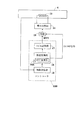
【選択図】 図2
PROBLEM TO BE SOLVED: To accurately control a control object having a small change by correcting a deviation due to a difference in apparatus accuracy.
In a process of numerically converting a control output value calculated in a calculation process by PID control into a control output value within a predetermined range by a numerical conversion unit, a digital calculation and a D / A converter are performed by a correction calculation unit. The deviation generated due to the difference in device accuracy is corrected to the actual control output value and the output time after the numerical conversion, and the corrected actual control output value is D / A converted and output to the power regulator 14. .
[Selection] Figure 2
Description
本発明は、温度、圧力、流量、レベルなどの物理量のプロセス制御に用いるプロセス制御方法およびこれを用いた装置、並びにシート状物製造方法およびシート状物に関する。 The present invention relates to a process control method used for process control of physical quantities such as temperature, pressure, flow rate, and level, an apparatus using the same, a sheet-like material manufacturing method, and a sheet-like material.
従来、工業・化学プラントでは温度、圧力、流量、レベル制御に、例えばPID制御が利用されている。このPID制御は、製造対象物の製造プロセスにおいて、制御対象である物理量の実測値と予め設定した基準値を比較し、求まる偏差を小さくするための演算制御出力値をデジタル演算機器により算出し、その結果をアナログ信号に変換した後に、当該アナログ信号にしたがって操作対象の操作量を調節している。このPID制御では、デジタル演算機器の算出結果の演算制御出力値に比例するアナログ信号に変換出力する連続比例方式や、算出結果の演算制御出力値にしたがって、操作対象のON/OFF操作のタイミングを調節する時間比例方式の2通りが提案・実施されている(例えば、特許文献1参照)。 Conventionally, in industrial / chemical plants, for example, PID control is used for temperature, pressure, flow rate, and level control. This PID control compares the actual measured value of the physical quantity to be controlled with a reference value set in advance in the manufacturing process of the manufacturing object, and calculates an arithmetic control output value for reducing the obtained deviation by a digital arithmetic device, After converting the result into an analog signal, the operation amount of the operation target is adjusted according to the analog signal. In this PID control, the ON / OFF operation timing of the operation target is set in accordance with a continuous proportional system that converts and outputs an analog signal proportional to the calculation control output value of the calculation result of the digital arithmetic device, or according to the calculation control output value of the calculation result. Two types of time proportional adjustment methods have been proposed and implemented (see, for example, Patent Document 1).
上述の連続比例方式と時間比例方式を利用してヒータに供給する電力を調節する制御機器を例に採って説明する。 A control device that adjusts the power supplied to the heater using the above-described continuous proportional method and time proportional method will be described as an example.
連続比例方式の場合、製造プロセスにおいて制御対象である温度(実測値)を熱電対を利用してデジタル制御機器に入力し、この実測値とデジタル制御機器に予め記憶されている温度の基準値を比較し、求まる偏差に応じて0〜100%の制御出力値(MV)をデジタル値として取得している。さらに、当該制御出力値を次式(1)を利用して4〜20mAのアナログ値(AO)に変換し、ヒータに供給する電力を調節する電力調節器に出力する。電力調節器では、入力されたアナログ値の4〜20mAの信号と電力調節器自体の最大出力電力(Pmax)を比較し、次式(2)からヒータに供給する電力(PA)を決定している。 In the case of the continuous proportional method, the temperature to be controlled (actually measured value) in the manufacturing process is input to the digital control device using a thermocouple, and the reference value of the actually measured value and the temperature stored in advance in the digital control device is used. The control output value (MV) of 0 to 100% is acquired as a digital value according to the obtained deviation. Further, the control output value is converted into an analog value (AO) of 4 to 20 mA using the following expression (1), and is output to a power regulator that adjusts the power supplied to the heater. The power regulator compares the input analog signal of 4 to 20 mA with the maximum output power (Pmax) of the power regulator itself, and determines the power (PA) to be supplied to the heater from the following equation (2). Yes.
AO=16/100×MV+4 … (1)
PA=Pmax(AO−4)/16 … (2)
AO = 16/100 × MV + 4 (1)
PA = Pmax (AO-4) / 16 (2)
また、時間比例方式の場合、デジタル制御機器により0〜100%の制御出力(MV)をデジタル値で取得する。さらに、デジタル制御機器に予め設定されている所定の時間間隔で演算処理を行う演算周期(CP[msec])と、制御出力(MV)からヒータに電力を供給する時間(PON[msec])と供給しない時間(POFF[msec])を次式(3),(4)を利用して決定している。つまり、電力を供給するON信号と供給しないOFF信号を所定の時間間隔で交互に出力している。 In the case of the time proportional method, 0 to 100% of the control output (MV) is acquired as a digital value by the digital control device. Furthermore, a calculation cycle (CP [msec]) for performing calculation processing at a predetermined time interval set in advance in the digital control device, and a time (PON [msec]) for supplying power to the heater from the control output (MV) The non-supply time (POFF [msec]) is determined using the following equations (3) and (4). That is, an ON signal that supplies power and an OFF signal that does not supply power are alternately output at predetermined time intervals.
PON=CP×MV/100 … (3)
POFF=CP×(100−MV)/100 … (4)
POFF = CP × (100−MV) / 100 (4)
しかしながら、従来の方式を利用したデジタル制御機器では次のような問題がある。 However, the digital control device using the conventional method has the following problems.
すなわち、デジタル制御機器で算出されるデジタル値の制御出力をアナログ変換(D/A変換)する場合に、装置精度により分解能が悪くなるといった問題がある。 That is, there is a problem that the resolution is deteriorated due to the accuracy of the apparatus when the control output of the digital value calculated by the digital control device is analog-converted (D / A conversion).
一般的なデジタル制御機器では、8〜10ビットのD/A変換が利用されている。そのため、デジタル制御機器により浮動小数点演算された制御出力値は、小数点以下12位までを有効桁数として算出されている。しかしながら、算出された制御出力値をD/A変換するときには、小数点以下1位までを有効桁数とするので、変換後の分解能が悪くなる。したがって、算出されるデジタル値である制御出力値が、小数点2位以下で連続的に変化していても、D/A変換されたときには、その数値変化はアナログ信号には反映されない。その結果、制御出力値がアナログ信号変換後に4.1以下となる値で制御したい場合は、アナログ信号にその値が反映されずに動作すべき操作対象が動作せず、変化量の小さい制御対象を精度よく制御することができないといった問題が発生している。 In general digital control equipment, D / A conversion of 8 to 10 bits is used. For this reason, the control output value calculated by the floating point calculation by the digital control device is calculated with the number of significant digits up to the 12th decimal place. However, when the calculated control output value is D / A converted, the first digit after the decimal point is used as the number of significant digits, so that the resolution after conversion becomes worse. Therefore, even if the calculated control output value, which is a digital value, continuously changes below the second decimal place, the numerical change is not reflected in the analog signal when D / A conversion is performed. As a result, when the control output value is to be controlled to a value that is 4.1 or less after analog signal conversion, the operation target that should operate without the value being reflected in the analog signal does not operate, and the control target has a small amount of change. There is a problem that it is not possible to control the system accurately.
本発明はこのような事情に鑑みてなされたものであって、プロセス制御において制御対象を精度よく制御することのできるプロセス制御方法およびこれを用いた装置、並びにシート状物製造方法およびシート状物を提供することを主たる目的としている。 The present invention has been made in view of such circumstances, and a process control method capable of accurately controlling a control target in process control, an apparatus using the same, a sheet-like material manufacturing method, and a sheet-like material The main purpose is to provide
第1の発明は、予め設定した制御対象の基準値と実測値の比較から求まる偏差を利用し、制御するための制御出力値をデジタル演算器により算出した後に、デジタル値である制御出力値をD/A変換器によりアナログ信号に変換し、このアナログ信号にしたがって操作対象を操作しながら制御対象を制御するプロセス制御方法において、
前記デジタル演算器とD/A変換器の精度差によって発生する制御出力値の偏差を、実制御出力値と出力時間によって補うように補正演算処理することを特徴とする。
The first invention uses a deviation obtained from a comparison between a preset reference value of a control target and an actual measurement value, calculates a control output value for control by a digital computing unit, and then calculates a control output value that is a digital value. In a process control method for converting a D / A converter into an analog signal and controlling the control target while operating the operation target according to the analog signal,
A correction calculation process is performed so that a deviation of a control output value generated due to a difference in accuracy between the digital calculator and the D / A converter is compensated by an actual control output value and an output time.
(作用・効果) この方法によると、デジタル演算器とD/A変換器の精度差によって発生する偏差を実制御出力値と出力時間によって補うことにより、出力することのできなかった偏差分を反映させて制御対象を制御することができる。すなわち、変化の小さい制御対象の変化量を偏差に含ませた状態で制御対象を制御することができるので、制御対象を精度よく制御することができる。 (Action / Effect) According to this method, the deviation generated by the difference in accuracy between the digital computing unit and the D / A converter is compensated by the actual control output value and the output time, thereby reflecting the deviation that could not be output. It is possible to control the controlled object. In other words, the control object can be controlled in a state in which the variation of the control object with a small change is included in the deviation, so that the control object can be accurately controlled.
第2の発明は、第1の発明において、前記補正演算処理は、以下の過程を備える、
(A)前記デジタル演算器で算出した理論制御出力値の浮動小数点以下の有効桁数をD/A変換器の浮動小数点の有効桁数まで切り上げ調整する過程と、
(B)当該補正演算処理を所定の時間間隔で行う演算周期内において、前記切り上げ調整後の実制御出力値の出力時間を、調整後の実制御出力値と調整前の理論制御出力値の比較により算出する過程と、
(C)前記調整後の実制御出力値と前記出力時間の開始時点と終了時点の値を前記D/A変換器に入力する過程と、
を備えたことを特徴とする。
In a second aspect based on the first aspect, the correction calculation process includes the following steps:
(A) A process of rounding up and adjusting the number of significant digits below the floating point of the theoretical control output value calculated by the digital computing unit to the number of significant digits of the floating point of the D / A converter;
(B) In the calculation cycle in which the correction calculation processing is performed at predetermined time intervals, the output time of the actual control output value after the round-up adjustment is compared with the actual control output value after adjustment and the theoretical control output value before adjustment. The process of calculating by
(C) a process of inputting the adjusted actual control output value and the start time and end time values of the output time to the D / A converter;
It is provided with.
(作用・効果) この方法によると、デジタル演算器で算出した理論制御出力値の浮動小数点以下の有効桁数をD/A変換器の浮動小数点の有効桁数に合せるために、その有効桁数まで理論制御出力値を所定の浮動小数点以下まで切り上げ調整する。また、調整前後の両制御出力値を比較して、調整後の実制御出力値を所定の演算周期内で出力する出力時間を求め、実制御出力値と出力時間によって偏差分を補う。したがって、出力することのできなかった機器の精度差による偏差分を制御出力することができる。 (Function / Effect) According to this method, the number of significant digits of the theoretical control output value calculated by the digital arithmetic unit is adjusted to match the number of significant digits of the floating point of the D / A converter. The theoretical control output value is adjusted up to a predetermined floating point. Further, both control output values before and after the adjustment are compared to obtain an output time for outputting the adjusted actual control output value within a predetermined calculation cycle, and the deviation is compensated by the actual control output value and the output time. Therefore, it is possible to control and output a deviation due to a difference in accuracy of devices that could not be output.
すなわち、変換精度の低い汎用のD/A変換器を用いても、D/A変換器自体の最小出力値未満の値を制御出力することができる。その結果、汎用のD/A変換器を利用しながらも精度の高いプロセス制御を安価に構築することができる。 That is, even if a general-purpose D / A converter with low conversion accuracy is used, a value less than the minimum output value of the D / A converter itself can be controlled and output. As a result, highly accurate process control can be constructed at low cost while using a general-purpose D / A converter.
第3の発明は、第2の発明において、前記補正演算処理は、さらに以下の過程を備える、
(D)理論制御出力値の閾値を予め設定しておき、前記デジタル演算器で算出された理論制御出力値と閾値を比較し、
(D1)前記理論制御出力値が閾値以上の場合は、理論制御出力値と未補正の出力時間をD/A変換器に入力する過程と、
(D2)前記理論制御出力値が閾値未満の場合は、前記(A)過程から(C)過程の補正演算処理を行う過程と、
を備えたことを特徴とする。
In a third aspect based on the second aspect, the correction calculation process further includes the following steps:
(D) A threshold value of the theoretical control output value is set in advance, and the theoretical control output value calculated by the digital calculator is compared with the threshold value.
(D1) When the theoretical control output value is greater than or equal to a threshold value, a process of inputting the theoretical control output value and the uncorrected output time to the D / A converter;
(D2) When the theoretical control output value is less than the threshold value, a process of performing the correction calculation process from the process (A) to the process (C);
It is provided with.
(作用・効果) この発明によると、理論制御出力値の閾値を予め設定しておくことで、理論制御出力値が閾値未満になった場合に、D/A変化したときに発生する偏差分を制御出力することができる。例えば、ヒータにより温度制御する場合に温度が略一定で温度変化が小さい状態で温度制御するとき、ヒータに電力供給することのできる制御出力値の最小値を閾値に設定する。このように閾値を設定すれば、制御出力値の最小値未満の値を偏差分として実制御出力と出力時間とで補って温度制御を行うことができる。すなわち、温度変化の小さい状態において、精度よく温度制御することができる。なお、温度に限らず、圧力、流量、レベル、および各種物理量の変化の小さい状態において適用することができる。 (Operation / Effect) According to the present invention, by setting the threshold value of the theoretical control output value in advance, when the theoretical control output value becomes less than the threshold value, the deviation generated when the D / A changes is obtained. Control output is possible. For example, when temperature control is performed with a heater and the temperature control is performed in a state where the temperature is substantially constant and the temperature change is small, the minimum value of the control output value that can supply power to the heater is set as the threshold value. If the threshold value is set in this way, the temperature control can be performed by compensating for the deviation of a value less than the minimum value of the control output value with the actual control output and the output time. That is, the temperature can be accurately controlled in a state where the temperature change is small. Note that the present invention is not limited to temperature, and can be applied in a state where changes in pressure, flow rate, level and various physical quantities are small.
第4の発明は、第1の発明において、前記補正演算処理は、以下の過程を備える、
(A)前記デジタル演算器で算出した理論制御出力値の浮動小数点以下の有効桁数をD/A変換器の浮動小数点の有効桁数まで切り上げ調整する過程と、
(B)当該補正演算処理を所定の時間間隔で行う演算周期内において、前記切り上げ調整後の実制御出力値の出力時間を、調整後の実制御出力値と調整前の理論制御出力値の比較により算出する過程と、
(E)前記調整後の実制御出力値を前記D/A変換器に入力する過程と、
(F)前記調整後の実制御出力値の出力時間の開始時点と終了時点に基づいて操作対象をON/OFF切換する切換信号に変換して前記操作対象に入力する過程と、
を備えたことを特徴とする。
In a fourth aspect based on the first aspect, the correction calculation process includes the following steps:
(A) A process of rounding up and adjusting the number of significant digits below the floating point of the theoretical control output value calculated by the digital computing unit to the number of significant digits of the floating point of the D / A converter;
(B) In the calculation cycle in which the correction calculation processing is performed at predetermined time intervals, the output time of the actual control output value after the round-up adjustment is compared with the actual control output value after adjustment and the theoretical control output value before adjustment. The process of calculating by
(E) inputting the adjusted actual control output value to the D / A converter;
(F) a process of converting the operation target into a switching signal for switching ON / OFF based on the start time and the end time of the output time of the actual control output value after the adjustment, and inputting to the operation target;
It is provided with.
(作用・効果) この発明によると、ON/OFF切換の切換信号をアナログ信号に変換することなく操作対象に直接に入力して操作することができ、操作対象の切換操作が容易となる。 (Operation / Effect) According to the present invention, an ON / OFF switching signal can be directly input to an operation object without being converted into an analog signal, and the operation object can be easily switched.
第5の発明は、加熱手段により加熱して溶融した原材料を当該加熱手段または/および冷却手段により加熱または/および冷却しながらシート状物を製造する過程において、予め設定した原材料の溶融温度の基準値と実測値の比較から求まる温度偏差を利用し、当該溶融温度を制御するための制御出力値をデジタル演算器により算出した後に、デジタル値である制御出力値をD/A変換器によりアナログ信号に変換し、このアナログ信号にしたがって加熱手段に供給する電力量または/および冷却手段に供給する冷却媒体の供給量を調整しながらシート状物を製造するシート状物製造方法において、
前記デジタル演算器とD/A変換器の精度差によって発生する制御出力値の偏差を、実制御出力値と出力時間によって補うように補正演算処理することを特徴とする。
According to a fifth aspect of the present invention, in the course of manufacturing a sheet-like material while heating or / and cooling the raw material heated and / or cooled by the heating means or the cooling means, a preset reference for the melting temperature of the raw material is set. After calculating the control output value for controlling the melting temperature using a digital calculator using the temperature deviation obtained from the comparison between the measured value and the measured value, the control output value, which is a digital value, is converted into an analog signal by the D / A converter. In the sheet-like material manufacturing method for manufacturing the sheet-like material while adjusting the amount of electric power supplied to the heating means or / and the supply amount of the cooling medium supplied to the cooling means according to the analog signal,
A correction calculation process is performed so that a deviation of a control output value generated due to a difference in accuracy between the digital calculator and the D / A converter is compensated by an actual control output value and an output time.
(作用・効果) この発明によると、デジタル演算器とD/A変換器の精度差によって発生する原材料の溶融温度の温度偏差を実制御出力値と出力時間によって補うことにより、出力することのできなかった温度偏差分を反映させることができる。つまり、原材料の溶融温度を制御するための加熱手段に供給する電力量と、冷却手段に供給する冷却媒体の供給量を調整することで実現することができる。すなわち、小さい温度変化の変化量を偏差に含ませた状態で温度制御することができるので、溶融温度を精度よく制御することができる。 (Operation / Effect) According to the present invention, it is possible to output by compensating the temperature deviation of the melting temperature of the raw material caused by the difference in accuracy between the digital arithmetic unit and the D / A converter by the actual control output value and the output time. The temperature deviation that did not exist can be reflected. That is, it can be realized by adjusting the amount of electric power supplied to the heating means for controlling the melting temperature of the raw material and the supply amount of the cooling medium supplied to the cooling means. That is, since temperature control can be performed in a state in which a small amount of change in temperature change is included in the deviation, the melting temperature can be accurately controlled.
なお、本発明における「シート状物」とは、フィルムおよびシートを含むものである。 The “sheet-like material” in the present invention includes a film and a sheet.
第6の発明は、第5の発明であるシート状物製造方法を利用して製造したことを特徴とするシート状物である。 A sixth aspect of the invention is a sheet-like material manufactured using the sheet-like material manufacturing method according to the fifth aspect of the invention.
(作用・効果) この発明によると、小さい温度変化の変化量を偏差に含ませた状態で制御することにより、シート状物製造過程における原材料の溶融温度を精度よく制御することがきるので、組成構造が均一となる高機能なシート状物が得られる。 (Operation / Effect) According to the present invention, the melting temperature of the raw material in the manufacturing process of the sheet-like material can be accurately controlled by controlling the change amount of the small temperature change in the deviation state. A highly functional sheet-like material having a uniform structure is obtained.
第7の発明は、予め設定した制御対象の基準値と実測値の比較から求まる偏差を利用し、デジタル演算処理により算出した制御出力値をD/A変換器によりアナログ信号に変換し、このアナログ信号にしたがって操作対象を操作しながら制御するプロセス制御装置において、
前記制御対象の基準値と実測値の比較から偏差を求めるとともに、この偏差から制御対象の演算制御出力値をデジタル演算により算出する制御演算手段と、
前記制御演算手段で算出された演算制御出力値に応じて制御対象への理論制御出力値に変換する数値変換手段と、
前記制御演算手段と前記数値変換手段とからなるデジタル演算器と前記D/A変換器との精度差によって発生する制御出力値の偏差を、実制御出力値と出力時間によって補正する補正演算手段と、
を備えたことを特徴とする。
The seventh invention uses a deviation obtained from a comparison between a preset reference value to be controlled and an actual measurement value, converts a control output value calculated by digital arithmetic processing into an analog signal by a D / A converter, In a process control device that controls an operation target according to a signal,
A control calculation unit that calculates a deviation from a comparison between the reference value of the control target and the actual measurement value, and calculates a calculation control output value of the control target by digital calculation from the deviation;
Numerical conversion means for converting into a theoretical control output value to be controlled according to the calculation control output value calculated by the control calculation means;
Correction arithmetic means for correcting a deviation of the control output value caused by the accuracy difference between the digital arithmetic unit comprising the control arithmetic means and the numerical value converting means and the D / A converter, based on the actual control output value and the output time; ,
It is provided with.
(作用・効果) この発明によると、制御演算手段は、制御対象の基準値と実測値の比較から偏差を求めるとともに、この偏差から制御対象の演算制御出力値をデジタル演算により算出する。数値変換手段は、制御演算手段で算出された演算制御出力値に応じて制御対象の制御出力値に変換する。補正演算手段は、前記制御演算手段と数値変換手段とからなるデジタル演算器と前記D/A変換器との精度差によって発生する制御出力値の偏差を、実制御出力値と出力時間によって補正する。したがって、この発明によると、第1および第2の発明を好適に実現することができる。 (Operation / Effect) According to the present invention, the control calculation means obtains a deviation from a comparison between the reference value of the control target and the actual measurement value, and calculates the calculation control output value of the control target from the deviation by digital calculation. The numerical value conversion means converts the control output value to be controlled according to the calculation control output value calculated by the control calculation means. The correction calculation means corrects the deviation of the control output value caused by the accuracy difference between the digital calculation unit composed of the control calculation unit and the numerical value conversion unit and the D / A converter by the actual control output value and the output time. . Therefore, according to this invention, the 1st and 2nd invention can be realized suitably.
第8の発明は、第7の発明において、前記プロセス制御装置は、さらに以下の構成を備える、
理論制御出力値の閾値を予め記憶する記憶手段と、
前記記憶手段に記憶された閾値と、前記数値変換手段により変換された理論制御出力値を比較し、理論制御出力値が閾値以上であれば、当該理論制御出力値と未補正の出力時間を前記D/A変換器に入力し、理論制御出力値が閾値未満であれば、前記補正演算手段により実制御出力値と出力時間によって補正するように判定する比較判定手段と、
を備えたことを特徴とする。
In an eighth aspect based on the seventh aspect, the process control apparatus further includes the following configuration.
Storage means for preliminarily storing a threshold value of the theoretical control output value;
The threshold value stored in the storage means and the theoretical control output value converted by the numerical value conversion means are compared. If the theoretical control output value is equal to or greater than the threshold value, the theoretical control output value and the uncorrected output time are A comparison / determination unit that inputs to the D / A converter and determines that the theoretical calculation output value is corrected by the actual calculation output value and the output time if the theoretical control output value is less than the threshold;
It is provided with.
(作用・効果) この発明によると、記憶手段は、理論制御出力値の閾値を予め記憶する。比較判定手段は、記憶手段に記憶された閾値と、数値変換手段により変換された理論制御出力値を比較し、理論制御出力値が閾値以上であれば、当該理論制御出力値と未補正の出力時間を前記D/A変換器に入力し、理論制御出力値が閾値未満であれば、補正演算手段により実制御出力値と出力時間によって補正するように判定する。したがって、この発明によると、第3の発明を好適に実現することができる。 (Operation / Effect) According to the present invention, the storage means stores in advance the threshold value of the theoretical control output value. The comparison determination means compares the threshold value stored in the storage means with the theoretical control output value converted by the numerical value conversion means, and if the theoretical control output value is equal to or greater than the threshold value, the theoretical control output value and the uncorrected output The time is input to the D / A converter, and if the theoretical control output value is less than the threshold value, it is determined by the correction calculation means to be corrected by the actual control output value and the output time. Therefore, according to the present invention, the third invention can be suitably realized.
第9の発明は、予め設定した制御対象の基準値と実測値の比較から求まる偏差を利用し、デジタル演算処理により算出した制御出力値をD/A変換器によりアナログ信号に変換し、このアナログ信号にしたがって操作対象を操作しながら制御するプロセス制御装置において、
前記制御対象の基準値と実測値の比較から偏差を求めるとともに、この偏差から制御対象の演算制御出力値をデジタル演算により算出する制御演算手段と、
前記制御演算手段で算出された演算制御出力値に応じて制御対象の理論制御出力値に変換する数値変換手段と、
前記制御演算手段と前記数値変換手段とからなるデジタル演算器と前記D/A変換器との精度差によって発生する制御出力値の偏差を、実制御出力値と出力時間によって補正する補正演算手段とを備え、
かつ、前記補正演算手段によって算出した一方の実制御出力値はD/A変換器に入力され、他方の補正した実制御出力値の出力時間は、その出力開始時点と終了時点に基づいて操作対象をON/OFF切換する切換信号に変換されて操作対象に入力されるように構成した、
ことを特徴とする。
A ninth invention uses a deviation obtained from a comparison between a preset reference value of a controlled object and an actual measurement value, converts a control output value calculated by digital arithmetic processing into an analog signal by a D / A converter, In a process control device that controls an operation target according to a signal,
A control calculation unit that calculates a deviation from a comparison between the reference value of the control target and the actual measurement value, and calculates a calculation control output value of the control target by digital calculation from the deviation;
Numerical conversion means for converting into a theoretical control output value to be controlled according to the calculation control output value calculated by the control calculation means;
Correction arithmetic means for correcting a deviation of the control output value caused by the accuracy difference between the digital arithmetic unit comprising the control arithmetic means and the numerical value converting means and the D / A converter, based on the actual control output value and the output time; With
In addition, one actual control output value calculated by the correction calculating means is input to the D / A converter, and the output time of the other corrected actual control output value is an operation target based on the output start time and end time. Is converted into a switching signal for ON / OFF switching and input to the operation target.
It is characterized by that.
(作用・効果) この発明によると、制御演算手段は、制御対象の基準値と実測値の比較から偏差を求めるとともに、この偏差から演算制御出力値をデジタル演算により算出する。数値変換手段は、制御演算手段で算出された演算制御出力値に応じて制御対象の制御出力値に変換する。補正演算手段は、制御演算手段と数値変換手段とからなるデジタル演算器とD/A変換器との精度差によって発生する制御出力値の偏差を、実制御出力値と出力時間によって補正する。さらに、補正演算手段によって算出した一方の実制御出力値はD/A変換器に入力され、他方の補正した実制御出力値の出力時間は、その出力開始時点と終了時点に基づいて操作対象をON/OFF切換する切換信号に変換されて操作対象に入力されるように構成する。したがって、この発明によると、第4の発明を好適に実現することができる。 (Operation / Effect) According to the present invention, the control calculation means obtains a deviation from the comparison between the reference value of the controlled object and the actual measurement value, and calculates the calculation control output value from this deviation by digital calculation. The numerical value conversion means converts the control output value to be controlled according to the calculation control output value calculated by the control calculation means. The correction calculation means corrects the deviation of the control output value caused by the accuracy difference between the digital calculation unit composed of the control calculation means and the numerical value conversion means and the D / A converter, based on the actual control output value and the output time. Further, one actual control output value calculated by the correction calculation means is input to the D / A converter, and the output time of the other corrected actual control output value is determined based on the output start time and end time. It is configured to be converted into a switching signal for switching ON / OFF and input to the operation target. Therefore, according to the present invention, the fourth invention can be suitably realized.
この発明に係るプロセス制御方法およびこれを用いた装置は、デジタル演算器とD/A変換器の精度差によって発生する制御出力値の偏差を実制御出力値と出力時間によって補うことにより、出力することのできなかった偏差分を反映させて制御対象を制御することができる。すなわち、変化の小さい制御対象の変化量を偏差に含ませた状態で制御対象を制御することができるので、制御対象を精度よく制御することができる。 The process control method and the apparatus using the same according to the present invention output by compensating the deviation of the control output value caused by the accuracy difference between the digital arithmetic unit and the D / A converter by the actual control output value and the output time. The control object can be controlled by reflecting the deviation that could not be obtained. In other words, the control object can be controlled in a state in which the variation of the control object with a small change is included in the deviation, so that the control object can be accurately controlled.
以下、図面を参照して本発明の実施例を説明する。 Embodiments of the present invention will be described below with reference to the drawings.
なお、本実施例の場合、フィルム製造用の押出機においてフィルム製造時の樹脂(材料)温度をシリンダの温度制御によって調節する場合を例に採って説明する。このフィルムは、本発明のシート状物に相当する。 In addition, in the case of a present Example, it demonstrates taking the case where the resin (material) temperature at the time of film manufacture is adjusted by temperature control of a cylinder in the extruder for film manufacture. This film corresponds to the sheet-like material of the present invention.
図1は、押出機の概略構成を示す側面図、図2はシリンダおよびその周りの概略構成を示すブロック図である。 FIG. 1 is a side view showing a schematic configuration of an extruder, and FIG. 2 is a block diagram showing a schematic configuration of a cylinder and its surroundings.
本実施例に用いる押出機1は、ペレット状のプラスチックなどの材料2を供給するホッパー3と、内装したスクリュー4によって材料2を摩擦・剪断しながら搬送する搬送部5と、搬送部内の材料2を加熱するシリンダ6と、搬送部内で溶融した材料2を冷却して硬化させる冷却ロール8の表面に塗工するダイ7とから構成されている。
The
なお、押出機1からロールに塗工されてフィルム成形された材料2は、厚み調節ロール9、搬送ロール群r、フィルム化された材料2の表面処理(例えばコロナ処理など)を行う表面処理部10の順で搬送処理され、回収部であるターレット11に巻取り回収されるようになっている。以下、各部の構成について具体的に説明する。
In addition, the
シリンダ6は、搬送部5の基端から先端に向かって略等間隔に複数個(例えば図1では5個)付設されている。各シリンダ内には、加熱手段としてのヒータ類と、冷却手段として冷却水を循環させることのできる配管(図示しない)を備えた構成をしている。また、図2に示すように、加熱手段を調節するための各種出力信号を送信するコントローラ12が設けられている。なお、コントローラ12については後述する。
A plurality of cylinders 6 (for example, five in FIG. 1) are attached at substantially equal intervals from the base end to the tip end of the transport unit 5. Each cylinder has a configuration including heaters as heating means and piping (not shown) through which cooling water can be circulated as cooling means. Moreover, as shown in FIG. 2, the
加熱手段は、ヒータ13と、ヒータ13に電力を供給する電力調節器14とから構成されている。なお、電力調節器14としては、例えば、サイリスタが利用されるがこれに限定されるものではない。
The heating means includes a
図1に戻って、塗工材料の厚みを調節するロール9は、例えば金属やゴム製のものが適宜に利用される。また、冷却ロール8は、そのロール内部に冷却水が循環するようになっている。つまり、溶融した材料2がロール上で均一に延伸される過程で、冷却硬化されるようになっている。
Returning to FIG. 1, as the roll 9 for adjusting the thickness of the coating material, for example, a metal or rubber roll is appropriately used. The
次に、本実施例の特徴であるプロセスの制御方法として、上述の押出機1を用いてシリンダ6の温度を制御する場合について図2に示すコントローラ12の構成を参照しながら具体的に説明する。なお、本実施例では、熱電対Sにより検出した温度の実測値を利用しコントローラ内でPID制御用の制御出力値(0〜100%)をデジタル演算して算出するとともに、算出されたデジタル値を4〜20mAのアナログ信号に変換して電力調節器14に適時に入力するようになっている。
Next, as a process control method that is a feature of the present embodiment, a case where the temperature of the cylinder 6 is controlled using the above-described
図2に示すように、コントローラ12は、制御演算部15と、数値変換部16と、D/A変換器17とから構成されている。なお、制御演算部15は、本発明の制御演算手段に、数値変換部16は数値変換手段にそれぞれ相当する。
As shown in FIG. 2, the
制御演算部15は、熱電対Sにより検出されたシリンダ6の温度(実測値)が入力され、この入力された実測値と制御演算部15に予め設定された製造プロセスにおける温度プロファイルの基準値を比較して偏差を算出し、この偏差を利用してヒータ13への電力供給をPID制御による演算制御出力値(MV0)としてデジタル演算により算出する。本実施例において算出される演算制御出力値(MV0)は、小数点12位以下の有効桁数を含む0〜100%の値である。
The
数値変換部16は、制御演算部15で算出された小数点12以下の有効桁数を含むデジタル値である0〜100%の演算制御出力値(MV0)を前述の式(1)を利用し、アナログ信号の4〜20mAに変換する。
The numerical
さらに、数値変換部16は、デジタル値をアナログ信号に変換する前にデジタル演算とアナログ変換により発生する精度差を補うように調整および補正する補正演算部16Aを備える。つまり、アナログ信号に変換する前段階の実制御出力値(MV2)と実制御出力値(MV2)の出力時間を算出する。なお、補正演算部16Aは、本発明の補正演算手段に相当する。
Furthermore, the numerical
具体的な演算は、式(1)を利用して算出された小数点12以下の値を含む4〜20の暫定の理論制御出力値(MV1)の小数点1以下有効の分解能となるように小数点2位の値を切り上げた実制御出力値(MV2)として4.0〜20.0の範囲の値に変換する。なお、この切り上げ調整は、後述するD/A変換器17の最初の出力値に合せたものである。
Specifically, the
例えば、コントローラ12から電力調節器14にアナログ信号を送信するように行なわれる演算処理の演算周期が、図3(a)に示すように1秒間隔であって、先の演算周期t0において算出された演算制御出力値(MV0)の値が38.125(%)から後の演算周期t1において算出された演算制御出力値(MV0)の値が38.50(%)に変化した場合において、式(1)を利用して数値変換した理論制御出力値(MV1)を算出すると、演算周期t0における理論制御出力値(MV1)は10.1、制御周期t1における理論制御出力値(MV1)は10.16となる。
For example, the calculation cycle of calculation processing performed to transmit an analog signal from the
ここで、従来装置の場合であれば、小数点1以下有効の分解能としてD/A変換してアナログ信号を出力するために、小数点2位以下を切り下げた場合に1秒ごとの各演算周期t0および演算周期t1では、図3の矢印Aで示す(b)のように、それぞれが10.1mAの値が演算周期の1秒間に連続的に電力調節器14に出力されることになる。図示しないが、逆に小数点2位を切り上げた場合は、10.2mAの値が演算周期の1秒間に連続的に電力調節器14に出力されることになる。
Here, in the case of the conventional apparatus, in order to output an analog signal by performing D / A conversion with an effective resolution of
しかしながら、本実施例の押出機1の数値変換部16の補正演算部16Aでは、さらに次のような処理が行なわれる。
However, the
すなわち、理論制御出力値(MV1)の値の小数点2位の値を切り上げた実制御出力値(MV2)を求め、さらに、理論制御出力値(MV1)と実制御出力値(MV2)の偏差を実制御出力値(MV2)の出力時間で補う。 That is, an actual control output value (MV2) obtained by rounding up the value of the theoretical control output value (MV1) to the second decimal place is obtained, and further, the deviation between the theoretical control output value (MV1) and the actual control output value (MV2) is calculated. Complement with the output time of the actual control output value (MV2).
具体的には、演算周期t秒、実制御出力値(MV2)の最小分解能r(本実施例では0.1)、MV0×16/100+4=x+a(ただし、xは実制御出力値(MV2)の最小分解能で制限される小数点yまで有効な実数で、0<a<r)とした場合に、所定分解能となるように所定の小数点以下の値を切り上げて求めた実制御出力値(MV2)を出力する第1出力時間値(ON)と、出力しない第2出力時間値(OFF)とを次式(5)、(6)により求める。 Specifically, the calculation cycle is t seconds, the minimum resolution r (0.1 in this embodiment) of the actual control output value (MV2), MV0 × 16/100 + 4 = x + a (where x is the actual control output value (MV2)) The actual control output value (MV2) obtained by rounding up the value below the predetermined decimal point so that the predetermined resolution is obtained when the real number is valid up to the decimal point y limited by the minimum resolution and 0 <a <r) The first output time value (ON) for outputting and the second output time value (OFF) for not outputting are obtained by the following equations (5) and (6).
第1出力時間値(ON)=(x+a)/(x+r)×t(秒) … (5)
第2出力時間値(OFF)=(r−a)/(x+r)×t(秒) … (6)
First output time value (ON) = (x + a) / (x + r) × t (seconds) (5)
Second output time value (OFF) = (r−a) / (x + r) × t (seconds) (6)
例えば、演算周期t0と演算周期t1とでは次にようになる。図3(a)に示すように、演算周期t0では、演算制御出力値(MV0)が図3の(c)に示すように、38.125(%)であって、数値変換して求めた実制御出力値(MV2)が10.1として算出される。この実制御出力値(MV2)が演算周期内で連続的に出力される。 For example, the calculation cycle t0 and the calculation cycle t1 are as follows. As shown in FIG. 3A, in the calculation cycle t0, the calculation control output value (MV0) is 38.125 (%) as shown in FIG. The actual control output value (MV2) is calculated as 10.1. This actual control output value (MV2) is continuously output within the calculation cycle.
これに対して、理論制御出力値(MV1)が10.1から10.16変化した演算周期t1では、数値変換して求めた実制御出力値(MV2)は小数点2位を切り上げて10.2となる。つまり、実制御出力値(MV2)を10.16から10.2に切り上げた偏差分だけの時間補正をした第1出力時間値(ON)と第2出力時間値(OFF)を上述の式(5),(6)を用いて算出する。具体的には、演算時刻t1からt2の1秒間に10.2mAを10.16/10.2秒間出力し、10.1mAを0.04/10.2秒間出力するようにする。なお、本実施例では、第1出力時間に実制御出力値(MV2)を出力するようにし、第2出力時間は出力しないようになっている。換言すれば、第1出力時間値(ON)および第2出力時間値(OFF)は、演算周期tの1秒間で実制御出力値(MV2)の出力時間を切り換えるON/OFFのタイミングを決定している。この補正演算部16Aで算出された実制御出力値(MV2)と実制御出力値を時間補正したON/OFF信号をD/A変換器17に送信する。
On the other hand, in the calculation cycle t1 in which the theoretical control output value (MV1) changes from 10.1 to 10.16, the actual control output value (MV2) obtained by numerical conversion is rounded up to the second decimal place to 10.2. It becomes. That is, the first output time value (ON) and the second output time value (OFF) obtained by correcting the actual control output value (MV2) by a deviation amount obtained by rounding up the actual control output value (MV2) from 10.16 to 10.2. Calculate using 5) and (6). Specifically, 10.2 mA is output for 10.16 / 10.2 seconds and 10.1 mA is output for 0.04 / 10.2 seconds in one second from the calculation time t1 to t2. In this embodiment, the actual control output value (MV2) is output during the first output time, and the second output time is not output. In other words, the first output time value (ON) and the second output time value (OFF) determine the ON / OFF timing for switching the output time of the actual control output value (MV2) in one second of the calculation cycle t. ing. The actual control output value (MV2) calculated by the
次に、D/A変換器17は、数値変換部16の補正演算部16Aから出力される出力時間の調整された、演算周期内で制御出力をON/OFF切り換えするタイミングの信号と実制御出力値(MV2)をデジタル信号からアナログ信号に変換する。
Next, the D /
D/A変換器17により変換されたアナログ信号は、電力調節器14に送信される。電力調節器14は、入力された4〜20mAのアナログ信号と電力調節器自体の最大出力電力を利用し、式(2)からヒータ13に供給する電力を決定する。
The analog signal converted by the D /
以上の処理が製造対象物のフィルムの製造が完了するまで、所定の演算周期ごとに行なわれる。 The above processing is performed every predetermined calculation cycle until the manufacture of the film to be manufactured is completed.
上述のように、制御演算部15によって算出された演算制御出力値(MV0)を所定の数値に単純に変換して同じ浮動小数点以下の有効桁数を有する理論制御出力値(MV1)をD/A変換した場合に、切り捨てられる所定の浮動小数点以下の値を切り上げ調整した実制御出力値(MV2)を求め、さらに、理論制御出力値(MV1)と実制御出力値(MV2)の偏差分を実制御出力値(MV2)の出力時間に時間補正することにより、従来装置では、制御出力として反映させることができなかった偏差分を出力することができる。つまり、制御対象である温度変化が小さい場合であっても、検出された微小な変化に対応してシリンダ6の温度制御が可能となる。
As described above, the arithmetic control output value (MV0) calculated by the control
また、D/A変換により発生していた分解能の低下を解消することができる。その結果、一般に利用されている、例えば8〜10ビット程度のD/A変換器を利用しても、温度などの制御対象を精度よく制御することができる。 In addition, it is possible to eliminate a decrease in resolution that has occurred due to D / A conversion. As a result, a control target such as temperature can be accurately controlled even when a generally used D / A converter of about 8 to 10 bits is used.
本実施例では、数値変換部16で算出される理論制御出力値(MV1)に対する閾値を予め設定しておき、演算周期ごとに算出される理論制御出力値(MV1)が閾値以上である場合は、求まる理論制御出力値(MV1)の小数点以下を所定の有効桁数に調整した実制御出力値(MV2)を演算周期内で連続的に出力し、閾値未満の場合には、上述の実施例1と同様に数値変換部16の補正演算部16Aにおいて演算周期内での出力時間を調整した実制御出力値(MV2)を演算処理により求めるように構成したものである。
In this embodiment, a threshold value for the theoretical control output value (MV1) calculated by the numerical
すなわち、本実施例のコントローラ12Aは、図4に示すように、数値変換部内に記憶手段に相当する記憶部18と比較判定手段に相当する比較判定部19を備えている。当該比較判定部19が、数値変換部16で変換された理論制御出力値(MV1)が記憶部18に予め設定した閾値未満であるか否かを判定するようになっている。なお、数値変換部内に記憶部18と比較判定部19を備える以外は上述の実施例1と同じ構成であるので、同じ部分には同一符号を付すに留め詳細な説明は省略する。以下、上述の押出機1を用いた場合を例に採って、その処理を具体的に説明する。
That is, as shown in FIG. 4, the
押出機1でフィルムを製造する場合、ホッパー3から投入したペレット状のプラスチックを溶融するために初期段階で温度を上昇させた後、プラスチックが溶融した状態からは温度を一定に保つようされている。そこで、本実施例では、温度を一定に保つ状態の工程で、シリンダ6に内装したヒータ温度を微調整する場合を示す。
When the film is produced by the
したがって、温度を一定に保つ工程では、シリンダ6の温度変化も小さいので制御出力も小さくなること、かつ、D/A変換器17の最小出力値(4.1)を考慮して4.1を閾値として予め記憶部18に設定する。
Therefore, in the step of keeping the temperature constant, the temperature change of the cylinder 6 is small, so that the control output is also small, and 4.1 is taken into consideration in consideration of the minimum output value (4.1) of the D /
数値変換部16は、先ず、熱電対Sからの温度の実測値の入力に基づいて制御演算部15でヒータ温度をPID制御するための演算制御出力値(MV0)と、式(1)を利用して理論制御出力値(MV1)を算出する。これら演算制御出力値(MV0)および理論制御出力値(MV1)は、浮動小数点12位以下の値を含むものである。同時に、補正演算部16Aにより理論制御出力値(MV1)の小数点2位を切り上げ調整した実制御出力値(MV2)も算出する。
First, the numerical
次に、比較判定部19が記憶部18に記憶された閾値4.1を読み取り、この閾値と理論制御出力値(MV1)を比較する。比較の結果、理論制御出力値(MV1)が閾値の4.1以上である場合は、補正演算部16Aにより算出された実制御出力値(MV2)をD/A変換器17に送信する。
Next, the
比較の結果、理論制御出力値(MV1)が閾値の4.1未満の場合には、次のような演算処理を行う。例えば、制御演算部15で求まる演算制御出力値(MV0)=0.3125(%)の場合、数値変換部16により式(1)を利用して演算処理すると理論制御出力値(MV1)=4.05となる。
As a result of the comparison, when the theoretical control output value (MV1) is less than the threshold value 4.1, the following arithmetic processing is performed. For example, when the calculation control output value (MV0) = 0.3125 (%) obtained by the
ここで、補正演算部16Aにより理論制御出力値(MV1)の小数点2位を切り上げ調整した実制御出力値(MV2)=4.1を求める。さらに、演算周期内における実制御出力値(MV2)の両出力時間を調整する。つまり、実制御出力値(MV2)=4.1を出力する第1出力時間値(ON)が式(5)を利用して、4.05/4.1×t秒間と算出され、出力しない第2出力時間値(OFF)が式(6)を利用して、0.05/4.1×t秒間と算出され、それぞれがD/A変換器17に送信される。
Here, an actual control output value (MV2) = 4.1 obtained by rounding up and adjusting the second decimal place of the theoretical control output value (MV1) by the
なお、本実施例の押出機1では実制御出力値(MV2)=4.1はアナログ信号に変換すると出力されるが、この実制御出力値(MV2)が小数点2位以下を切り上げ調整したことにより、切り上げた分の偏差が出力時間により補正される。したがって、第2出力時間値(OFF)は、実制御出力値(MV2)の出力を停止する時点を求めたことになる。
In the
D/A変換器17では、変換された実制御出力値(MV2)と第1出力時間値(ON)および第2出力時間値(OFF)がアナログ信号に変換され、当該アナログ信号が電力調節器14に送信される。以上で本実施例のコントローラ12Aでの一巡の演算処理が終了する。
In the D /
電力調節器14は、入力されたコントローラ12Aからのアナログ信号と電力調節器自体の最大出力電力とに基づいて式(2)を利用してヒータ13に供給する電力を決定する。
The
以上の処理が製造対象物のフィルムの製造が完了するまで、所定の演算周期ごとに行なわれる。 The above processing is performed every predetermined calculation cycle until the manufacture of the film to be manufactured is completed.
上述のように、制御対象であるシリンダ6の温度変化が小さく、かつ、D/A変換の最小出力値を考慮して閾値を予め設定しておくことにより、従来装置では、D/A変換時に切り捨てた偏差分を制御出力として反映させることができずに温度制御できなかった温度変化の小さい状態であっても、精度よく温度制御を行うことができる。 As described above, the temperature change of the cylinder 6 to be controlled is small, and the threshold value is set in advance in consideration of the minimum output value of D / A conversion. Even in a state where the change in temperature, which has been unable to reflect the rounded-off deviation as a control output and the temperature cannot be controlled, can be accurately controlled.
本発明は上述した実施例のものに限らず、次のように変形実施することもできる。 The present invention is not limited to the embodiment described above, and can be modified as follows.
(1)上記各実施例では、数値変換部16の補正演算部16Aで求めた実制御出力値(MV2)と第1出力時間値(ON)および第2出力時間値(OFF)のそれぞれをD/A変換器17でデジタル信号からアナログ信号に変化して電力調節器14に送信していたが、次のように構成してもよい。
(1) In each of the above embodiments, the actual control output value (MV2), the first output time value (ON), and the second output time value (OFF) obtained by the
例えば、図5に示すように、コントローラ12Bと電力調節器14の間に半導体リレーであるSSR(Solid State Relay)20を介在させ、数値変換部16の補正演算部16Aで算出した実制御出力値(MV2)はD/A変換されてSSR19に送信され、第1出力時間値(ON)および第2出力時間値(OFF)はSSR19をON/OFF切換する信号として数値変化部16から直接にSSR20に送信するように構成してもよい。この場合、実制御出力値(MV2)は、演算周期内で連続的に出力されるアナログ信号に変換されてSSR19を介して電力調節器14に送信され、その演算周期内における出力時間を数値変換部16から送信されるON/OFF信号に基づいて、SSR20が調節する。このように構成することにより、上述の実施例と同様の効果を奏する。
For example, as shown in FIG. 5, an actual control output value calculated by the
(2)上記各実施例では、シリンダ6にヒータ13を内装して温度調節する構成であったが、シリンダ6内の冷却用の冷却手段の配管に冷却水を供給循環させて同時に温度制御するように構成してもよい。この場合、ヒータ13と同様の制御方法を利用し配管に供給する略一定温度の冷却水の供給量をバルブ操作により行えばよい。このようにヒータ13と配管への冷却水の供給循環を併用してシリンダ6の温度制御を行うことにより、より精度よく温度制御を行うことがきる。
(2) In each of the above embodiments, the heater 6 is provided in the cylinder 6 to adjust the temperature. However, cooling water is supplied and circulated through the piping of the cooling means for cooling in the cylinder 6 to simultaneously control the temperature. You may comprise as follows. In this case, the amount of cooling water supplied at a substantially constant temperature supplied to the pipe using the same control method as the
(3)上記各実施例では、PID制御をもとに説明したが、PまたはPI制御にも適用することができる。また、デジタル演算器とD/A変換器を用いた各種制御装置にも適用することができる。これらの場合も、上述の実施例と同様の効果を奏する。 (3) In each of the above embodiments, the description has been made based on the PID control. However, the present invention can also be applied to the P or PI control. The present invention can also be applied to various control devices using a digital arithmetic unit and a D / A converter. In these cases, the same effects as those of the above-described embodiment can be obtained.
(4)上記各実施例では、押出機のシリンダ6の温度制御を例に採って説明したが、制御対象は温度に限らず、圧力、流量、およびレベルなどの物理量である制御対象に対して当該制御方法を適用することができる。また、押出機に限らず圧力などの物理量を制御対象とする機器や装置などにも適用することができる。 (4) In each of the above embodiments, the temperature control of the cylinder 6 of the extruder has been described as an example. However, the control target is not limited to the temperature, and the control target is a physical quantity such as pressure, flow rate, and level. The control method can be applied. Further, the present invention can be applied not only to an extruder but also to devices and apparatuses that control physical quantities such as pressure.
(5)上記各実施例では、シート状物としてのフィルムを製造する場合を例に採って説明したが、フィルム以外のシートを製造する場合にも適用することができる。 (5) In each of the above embodiments, the case where a film as a sheet-like material is manufactured has been described as an example, but the present invention can also be applied to the case where a sheet other than a film is manufactured.
S … 熱電対
1 … 押出機
6 … シリンダ
12 … コントローラ
13 … ヒータ
14 … 電力調節器
15 … 制御演算部
16 … 数値変換部
16A… 補正演算部
17 … D/A変換器
18 … 記憶部
19 … 比較判定部
DESCRIPTION OF SYMBOLS S ...
Claims (9)
前記デジタル演算器とD/A変換器の精度差によって発生する制御出力値の偏差を、実制御出力値と出力時間によって補うように補正演算処理することを特徴とするプロセス制御方法。 After calculating a control output value for control by a digital computing unit using a deviation obtained from a comparison between a preset reference value of a control target and an actual measurement value, the control output value which is a digital value is converted by a D / A converter. In the process control method of controlling the control object while converting the operation object according to the analog signal, converting to an analog signal,
A process control method, wherein a correction calculation process is performed so that a deviation of a control output value generated by a difference in accuracy between the digital arithmetic unit and the D / A converter is compensated by an actual control output value and an output time.
前記補正演算処理は、以下の過程を備える、
(A)前記デジタル演算器で算出した理論制御出力値の浮動小数点以下の有効桁数をD/A変換器の浮動小数点の有効桁数まで切り上げ調整する過程と、
(B)当該補正演算処理を所定の時間間隔で行う演算周期内において、前記切り上げ調整後の実制御出力値の出力時間を、調整後の実制御出力値と調整前の理論制御出力値の比較により算出する過程と、
(C)前記調整後の実制御出力値と前記出力時間の開始時点と終了時点の値を前記D/A変換器に入力する過程と、
を備えたことを特徴とするプロセス制御方法。 The process control method according to claim 1,
The correction calculation process includes the following steps:
(A) A process of rounding up and adjusting the number of significant digits below the floating point of the theoretical control output value calculated by the digital computing unit to the number of significant digits of the floating point of the D / A converter;
(B) In the calculation cycle in which the correction calculation processing is performed at predetermined time intervals, the output time of the actual control output value after the round-up adjustment is compared with the actual control output value after adjustment and the theoretical control output value before adjustment. The process of calculating by
(C) a process of inputting the adjusted actual control output value and the start time and end time values of the output time to the D / A converter;
A process control method comprising:
前記補正演算処理は、さらに以下の過程を備える、
(D)理論制御出力値の閾値を予め設定しておき、前記デジタル演算器で算出された理論制御出力値と閾値を比較し、
(D1)前記理論制御出力値が閾値以上の場合は、理論制御出力値と未補正の出力時間をD/A変換器に入力する過程と、
(D2)前記理論制御出力値が閾値未満の場合は、前記(A)過程から(C)過程の補正演算処理を行う過程と、
を備えたことを特徴とするプロセス制御方法。 The process control method according to claim 2, wherein
The correction calculation process further includes the following steps:
(D) A threshold value of the theoretical control output value is set in advance, and the theoretical control output value calculated by the digital calculator is compared with the threshold value.
(D1) When the theoretical control output value is greater than or equal to a threshold value, a process of inputting the theoretical control output value and the uncorrected output time to the D / A converter;
(D2) When the theoretical control output value is less than the threshold value, a process of performing the correction calculation process from the process (A) to the process (C);
A process control method comprising:
前記補正演算処理は、以下の過程を備える、
(A)前記デジタル演算器で算出した理論制御出力値の浮動小数点以下の有効桁数をD/A変換器の浮動小数点の有効桁数まで切り上げ調整する過程と、
(B)当該補正演算処理を所定の時間間隔で行う演算周期内において、前記切り上げ調整後の実制御出力値の出力時間を、調整後の実制御出力値と調整前の理論制御出力値の比較により算出する過程と、
(E)前記調整後の実制御出力値を前記D/A変換器に入力する過程と、
(F)前記調整後の実制御出力値の出力時間の開始時点と終了時点に基づいて操作対象をON/OFF切換する切換信号に変換して前記操作対象に入力する過程と、
を備えたことを特徴とするプロセス制御方法。 The process control method according to claim 1,
The correction calculation process includes the following steps:
(A) A process of rounding up and adjusting the number of significant digits below the floating point of the theoretical control output value calculated by the digital computing unit to the number of significant digits of the floating point of the D / A converter;
(B) In the calculation cycle in which the correction calculation processing is performed at predetermined time intervals, the output time of the actual control output value after the round-up adjustment is compared with the actual control output value after adjustment and the theoretical control output value before adjustment. The process of calculating by
(E) inputting the adjusted actual control output value to the D / A converter;
(F) a process of converting the operation target into a switching signal for switching ON / OFF based on the start time and the end time of the output time of the actual control output value after the adjustment, and inputting to the operation target;
A process control method comprising:
前記デジタル演算器とD/A変換器の精度差によって発生する制御出力値の偏差を、実制御出力値と出力時間によって補うように補正演算処理することを特徴とするシート状物製造方法。 In the process of manufacturing a sheet by melting the raw material while heating or / and cooling the raw material heated and heated by the heating means and / or cooling means, a preset reference value of the melting temperature of the raw material and After calculating the control output value for controlling the melting temperature using a digital calculator, using the temperature deviation obtained from the comparison of measured values, the control output value, which is a digital value, is converted into an analog signal by the D / A converter. In the sheet-like material manufacturing method for manufacturing the sheet-like material while adjusting the amount of electric power supplied to the heating means and / or the supply amount of the cooling medium supplied to the cooling means according to the analog signal,
A sheet-like material manufacturing method, wherein a correction calculation process is performed so that a deviation of a control output value generated due to a difference in accuracy between the digital calculator and the D / A converter is compensated by an actual control output value and an output time.
前記制御対象の基準値と実測値の比較から偏差を求めるとともに、この偏差から制御対象の演算制御出力値をデジタル演算により算出する制御演算手段と、
前記制御演算手段で算出された演算制御出力値に応じて制御対象への理論制御出力値に変換する数値変換手段と、
前記制御演算手段と前記数値変換手段とからなるデジタル演算器と前記D/A変換器との精度差によって発生する制御出力値の偏差を、実制御出力値と出力時間によって補正する補正演算手段と、
を備えたことを特徴とするプロセス制御装置。 Using the deviation obtained from the comparison between the preset reference value of the control target and the actual measurement value, the control output value calculated by the digital calculation process is converted into an analog signal by the D / A converter, and the operation target is determined according to the analog signal. In a process control device that controls while operating,
A control calculation unit that calculates a deviation from a comparison between the reference value of the control target and the actual measurement value, and calculates a calculation control output value of the control target by digital calculation from the deviation;
Numerical conversion means for converting into a theoretical control output value to be controlled according to the calculation control output value calculated by the control calculation means;
Correction arithmetic means for correcting a deviation of the control output value caused by the accuracy difference between the digital arithmetic unit comprising the control arithmetic means and the numerical value converting means and the D / A converter, based on the actual control output value and the output time; ,
A process control apparatus comprising:
理論制御出力値の閾値を予め記憶する記憶手段と、
前記記憶手段に記憶された閾値と、前記数値変換手段により変換された理論制御出力値を比較し、理論制御出力値が閾値以上であれば、当該理論制御出力値と未補正の出力時間を前記D/A変換器に入力し、理論制御出力値が閾値未満であれば、前記補正演算手段により実制御出力値と出力時間によって補正するように判定する比較判定手段と、
を備えたことを特徴とするプロセス制御装置。 The process control apparatus according to claim 7, wherein
Storage means for preliminarily storing a threshold value of the theoretical control output value;
The threshold value stored in the storage means and the theoretical control output value converted by the numerical value conversion means are compared. If the theoretical control output value is equal to or greater than the threshold value, the theoretical control output value and the uncorrected output time are A comparison / determination unit that inputs to the D / A converter and determines that the theoretical calculation output value is corrected by the actual calculation output value and the output time if the theoretical control output value is less than the threshold;
A process control apparatus comprising:
前記制御対象の基準値と実測値の比較から偏差を求めるとともに、この偏差から制御対象の演算制御出力値をデジタル演算により算出する制御演算手段と、
前記制御演算手段で算出された演算制御出力値に応じて制御対象の理論制御出力値に変換する数値変換手段と、
前記制御演算手段と前記数値変換手段とからなるデジタル演算器と前記D/A変換器との精度差によって発生する制御出力値の偏差を、実制御出力値と出力時間によって補正する補正演算手段とを備え、
かつ、前記補正演算手段によって算出した一方の実制御出力値はD/A変換器に入力され、他方の補正した実制御出力値の出力時間は、その出力開始時点と終了時点に基づいて操作対象をON/OFF切換する切換信号に変換されて操作対象に入力されるように構成した、
ことを特徴とするプロセス制御装置。
Using a deviation obtained from a comparison between a preset reference value of a control target and an actual measurement value, a control output value calculated by digital arithmetic processing is converted into an analog signal by a D / A converter, and an operation target is determined according to the analog signal. In a process control device that controls while operating,
A control calculation unit that calculates a deviation from a comparison between the reference value of the control target and the actual measurement value, and calculates a calculation control output value of the control target by digital calculation from the deviation;
Numerical conversion means for converting into a theoretical control output value to be controlled according to the calculation control output value calculated by the control calculation means;
Correction arithmetic means for correcting a deviation of the control output value caused by the accuracy difference between the digital arithmetic unit comprising the control arithmetic means and the numerical value converting means and the D / A converter, based on the actual control output value and the output time; With
In addition, one actual control output value calculated by the correction calculating means is input to the D / A converter, and the output time of the other corrected actual control output value is an operation target based on the output start time and end time. Is converted into a switching signal for ON / OFF switching and input to the operation target.
A process control device.
Priority Applications (1)
| Application Number | Priority Date | Filing Date | Title |
|---|---|---|---|
| JP2004105103A JP4632684B2 (en) | 2004-03-31 | 2004-03-31 | Process control method, apparatus using the same, and sheet-like material manufacturing method |
Applications Claiming Priority (1)
| Application Number | Priority Date | Filing Date | Title |
|---|---|---|---|
| JP2004105103A JP4632684B2 (en) | 2004-03-31 | 2004-03-31 | Process control method, apparatus using the same, and sheet-like material manufacturing method |
Publications (2)
| Publication Number | Publication Date |
|---|---|
| JP2005293050A true JP2005293050A (en) | 2005-10-20 |
| JP4632684B2 JP4632684B2 (en) | 2011-02-16 |
Family
ID=35325937
Family Applications (1)
| Application Number | Title | Priority Date | Filing Date |
|---|---|---|---|
| JP2004105103A Expired - Lifetime JP4632684B2 (en) | 2004-03-31 | 2004-03-31 | Process control method, apparatus using the same, and sheet-like material manufacturing method |
Country Status (1)
| Country | Link |
|---|---|
| JP (1) | JP4632684B2 (en) |
Cited By (1)
| Publication number | Priority date | Publication date | Assignee | Title |
|---|---|---|---|---|
| CN115067402A (en) * | 2021-07-02 | 2022-09-20 | 黄山优团电子科技有限公司 | Gantry double-column type rolling machine with floating type gland and automatic rolling method thereof |
-
2004
- 2004-03-31 JP JP2004105103A patent/JP4632684B2/en not_active Expired - Lifetime
Cited By (1)
| Publication number | Priority date | Publication date | Assignee | Title |
|---|---|---|---|---|
| CN115067402A (en) * | 2021-07-02 | 2022-09-20 | 黄山优团电子科技有限公司 | Gantry double-column type rolling machine with floating type gland and automatic rolling method thereof |
Also Published As
| Publication number | Publication date |
|---|---|
| JP4632684B2 (en) | 2011-02-16 |
Similar Documents
| Publication | Publication Date | Title |
|---|---|---|
| US20030102383A1 (en) | Controller, temperature controller and heat processor using same | |
| JP6345801B2 (en) | Temperature control method and temperature control device | |
| CN103397171B (en) | Method for determining furnace-temperature set value of billet heating furnace | |
| CN105018718A (en) | Heating furnace process furnace temperature control method based on thermal load distribution | |
| WO1996006719A1 (en) | Temperature control method for injection molding machine | |
| JP2007537537A (en) | Improved temperature control | |
| CZ233695A3 (en) | Tempering process of injection moulding machine units, particularly for treating crosslinked polymers and units of moulding tools for plastic treatment | |
| JP4780421B2 (en) | Control device | |
| JP4632684B2 (en) | Process control method, apparatus using the same, and sheet-like material manufacturing method | |
| US6039904A (en) | Method of adjusting a heat-displacing T-die | |
| JP7127591B2 (en) | TEMPERATURE CONTROL DEVICE, TEMPERATURE CONTROL METHOD, AND PROGRAM | |
| JPS6010893B2 (en) | Mold temperature control method and device | |
| JP3683677B2 (en) | Method of raising nozzle / cylinder temperature in injection molding machine | |
| JP4703101B2 (en) | Process control method | |
| CN112461010B (en) | Method, device and medium for reducing energy consumption of heating furnace to be rolled | |
| JPS6270904A (en) | Temperature control method | |
| JPH0422688B2 (en) | ||
| RU2068006C1 (en) | Method to control metal heating in flame heating furnace | |
| CN110262380B (en) | Microarray hot-press forming precision control system and method based on empirical process probability | |
| CN106544048A (en) | The heat accumulating type fast pyrogenation furnace temperature control method of control radial canal make-and-break time | |
| JP2025117657A (en) | Injection molding system, temperature rise timing control program, and temperature rise timing control method | |
| JP3234001B2 (en) | Vulcanizer temperature controller | |
| TWI877990B (en) | Control method of heating system | |
| TW202520785A (en) | Heating system and control method thereof | |
| JP3233994B2 (en) | Vulcanizer temperature controller |
Legal Events
| Date | Code | Title | Description |
|---|---|---|---|
| A621 | Written request for application examination |
Free format text: JAPANESE INTERMEDIATE CODE: A621 Effective date: 20061013 |
|
| A977 | Report on retrieval |
Free format text: JAPANESE INTERMEDIATE CODE: A971007 Effective date: 20080617 |
|
| A131 | Notification of reasons for refusal |
Free format text: JAPANESE INTERMEDIATE CODE: A131 Effective date: 20080624 |
|
| A521 | Request for written amendment filed |
Free format text: JAPANESE INTERMEDIATE CODE: A523 Effective date: 20080820 |
|
| A131 | Notification of reasons for refusal |
Free format text: JAPANESE INTERMEDIATE CODE: A131 Effective date: 20081007 |
|
| A521 | Request for written amendment filed |
Free format text: JAPANESE INTERMEDIATE CODE: A523 Effective date: 20081121 |
|
| A02 | Decision of refusal |
Free format text: JAPANESE INTERMEDIATE CODE: A02 Effective date: 20090113 |
|
| A521 | Request for written amendment filed |
Free format text: JAPANESE INTERMEDIATE CODE: A523 Effective date: 20090312 |
|
| A911 | Transfer to examiner for re-examination before appeal (zenchi) |
Free format text: JAPANESE INTERMEDIATE CODE: A911 Effective date: 20090323 |
|
| A912 | Re-examination (zenchi) completed and case transferred to appeal board |
Free format text: JAPANESE INTERMEDIATE CODE: A912 Effective date: 20090515 |
|
| A521 | Request for written amendment filed |
Free format text: JAPANESE INTERMEDIATE CODE: A523 Effective date: 20101020 |
|
| A01 | Written decision to grant a patent or to grant a registration (utility model) |
Free format text: JAPANESE INTERMEDIATE CODE: A01 |
|
| A61 | First payment of annual fees (during grant procedure) |
Free format text: JAPANESE INTERMEDIATE CODE: A61 Effective date: 20101116 |
|
| R150 | Certificate of patent or registration of utility model |
Ref document number: 4632684 Country of ref document: JP Free format text: JAPANESE INTERMEDIATE CODE: R150 Free format text: JAPANESE INTERMEDIATE CODE: R150 |
|
| FPAY | Renewal fee payment (event date is renewal date of database) |
Free format text: PAYMENT UNTIL: 20131126 Year of fee payment: 3 |
|
| FPAY | Renewal fee payment (event date is renewal date of database) |
Free format text: PAYMENT UNTIL: 20131126 Year of fee payment: 3 |
|
| FPAY | Renewal fee payment (event date is renewal date of database) |
Free format text: PAYMENT UNTIL: 20161126 Year of fee payment: 6 |
|
| R250 | Receipt of annual fees |
Free format text: JAPANESE INTERMEDIATE CODE: R250 |
|
| R250 | Receipt of annual fees |
Free format text: JAPANESE INTERMEDIATE CODE: R250 |
|
| R250 | Receipt of annual fees |
Free format text: JAPANESE INTERMEDIATE CODE: R250 |
|
| R250 | Receipt of annual fees |
Free format text: JAPANESE INTERMEDIATE CODE: R250 |
|
| R250 | Receipt of annual fees |
Free format text: JAPANESE INTERMEDIATE CODE: R250 |
|
| R250 | Receipt of annual fees |
Free format text: JAPANESE INTERMEDIATE CODE: R250 |
|
| R250 | Receipt of annual fees |
Free format text: JAPANESE INTERMEDIATE CODE: R250 |
|
| R250 | Receipt of annual fees |
Free format text: JAPANESE INTERMEDIATE CODE: R250 |
|
| R250 | Receipt of annual fees |
Free format text: JAPANESE INTERMEDIATE CODE: R250 |
|
| EXPY | Cancellation because of completion of term |