JP2005293032A - Vehicle operation state monitoring system and vehicle operation state monitoring program for this system - Google Patents
Vehicle operation state monitoring system and vehicle operation state monitoring program for this system Download PDFInfo
- Publication number
- JP2005293032A JP2005293032A JP2004104874A JP2004104874A JP2005293032A JP 2005293032 A JP2005293032 A JP 2005293032A JP 2004104874 A JP2004104874 A JP 2004104874A JP 2004104874 A JP2004104874 A JP 2004104874A JP 2005293032 A JP2005293032 A JP 2005293032A
- Authority
- JP
- Japan
- Prior art keywords
- vehicle
- driving
- data
- operation state
- abnormality
- Prior art date
- Legal status (The legal status is an assumption and is not a legal conclusion. Google has not performed a legal analysis and makes no representation as to the accuracy of the status listed.)
- Pending
Links
Images
Landscapes
- Traffic Control Systems (AREA)
Abstract
Description
本発明は、移動体通信を利用して、車輌の運転状況を遠隔監視する車輌運転状況監視システムに関する。 The present invention relates to a vehicle driving situation monitoring system that remotely monitors a driving situation of a vehicle using mobile communication.
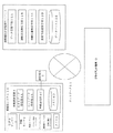
図8は、従来の道路情報管理システムの構成を概略的に示す図である。
従来の道路情報管理システムとしては、例えば特許文献1記載のように、既存の多数の業務用車輌MS1〜MSnにそれぞれ撮像カメラを備えた移動監視装置を搭載し、撮像カメラにより撮像した道路映像をGPSを利用して検出した位置情報とともに移動通信網MNWを介して道路情報管理センタSCへ無線伝送する。そして、道路情報管理センタSCにおいて、上記撮像情報を解析して渋滞や交通規制、天候などの道路の状況を認識し、その認識結果を表す道路情報を位置情報を基に地図上にマッピングした上で記憶部に記憶する。そして、業務用車輌MS1〜MSnは勿論のこと、一般的な移動局ユーザPS1〜PSmや固定局ユーザHS1〜HSiから配信要求が到来した場合に、この要求に応じた道路情報を記憶装置から選択的に読み出して要求元へ配信するものがあった。
また、道路情報を車輌に配信するだけでなく、上述のようなGPSを利用した道路情報管理システムを用いて、車載センサで検出した車輌の運転状況をGPSデータと組み合わせて記録し、運転状況の管理を行う車輌運転状況監視システムもあった。
FIG. 8 is a diagram schematically showing a configuration of a conventional road information management system.
As a conventional road information management system, for example, as described in
In addition to delivering road information to the vehicle, the vehicle driving status detected by the vehicle-mounted sensor is recorded in combination with GPS data using the above-described road information management system using GPS, and the driving status is recorded. There was also a vehicle operating status monitoring system that managed the vehicle.
しかしながら、従来の道路情報管理システムは上述のように構成されていたため、次のような課題があった。
車載機で車輌センサのデータを集積しIC(Integrated Circuit)カードに保存、運転終了後に事務所のPC(Personal Computer)でICカードのデータを読み込み、PCの解析プログラム等でデータを解析するものであった。この技術では運転状況は解析できるが運転手が運転を終了した後であり、危険運転がわかっても運転後に注意することしかできなかった。
However, since the conventional road information management system is configured as described above, there are the following problems.
The vehicle sensor data is collected by the in-vehicle device and stored in the IC (Integrated Circuit) card. After the operation is completed, the IC card data is read by the office PC (Personal Computer) and the data is analyzed by the PC analysis program. there were. Although this technology can analyze the driving situation, it is after the driver has finished driving, and even if he knew about dangerous driving, he could only be careful after driving.
本発明は、上述のような課題を解決するためになされたものであり、移動体通信を利用することにより車輌の運転中にリアルタイムでデータを送信してセンタシステム(サーバ)で解析を行い、危険運転が判明した場合に直ちに注意通知を発信することや警察に通報することにより、速度違反、居眠り運転や飲酒運転による交通事故を未然に防ぐ確率を高める車輌運転状況監視システムを提供することを目的とする。 The present invention has been made in order to solve the above-described problems. By using mobile communication, data is transmitted in real time during driving of a vehicle and analyzed by a center system (server). To provide a vehicle driving situation monitoring system that increases the probability of preventing traffic accidents caused by speeding, drowsy driving, or drunk driving by immediately sending a notice of warning or reporting to the police when dangerous driving is found Objective.
本発明の車輌運転状況監視システムは、ネットワークを通じて車輌側から所定時間毎に送信される車輌位置データ、運転状況データ及び時刻データを受信する運転状況データ受信手段と、前記運転状況データを解析し、運転状況における異常の有無を判定する運転状況解析手段と、前記運転状況解析手段によって運転状況の異常が判定されると、その異常内容をクライアント端末に送信する異常内容送信手段とを備える。 The vehicle driving situation monitoring system of the present invention analyzes driving situation data receiving means for receiving vehicle position data, driving situation data, and time data transmitted from the vehicle side every predetermined time through a network, and the driving situation data, Driving condition analyzing means for determining presence / absence of abnormality in the driving situation, and abnormality content transmitting means for transmitting abnormality contents to the client terminal when the driving condition analyzing means determines abnormality of the driving situation.
また、前記運転状況解析手段は、運転状況における異常として、速度超過、蛇行運転、急発進、急停止、または、居眠り運転のいずれかの有無を判定する。 Further, the driving state analyzing means determines whether there is any of overspeed, meandering, sudden start, sudden stop, or dozing operation as an abnormality in the driving state.
本発明の車輌運転状況監視プログラムは、コンピュータを、ネットワークを通じて車輌側から所定時間毎に送信される車輌位置データ、運転状況データ及び時刻データを受信する運転状況データ受信手段、前記運転状況データを解析し、運転状況における異常の有無を判定する運転状況解析手段、及び、前記運転状況解析手段によって運転状況の異常が判定されると、その異常内容をクライアント端末に送信する異常内容送信手段として機能させるためのプログラムである。 The vehicle driving situation monitoring program of the present invention analyzes a driving situation data receiving means for receiving vehicle position data, driving situation data and time data transmitted from a vehicle side every predetermined time through a network, and analyzes the driving situation data. And operating condition analyzing means for determining presence / absence of abnormality in the driving condition, and when abnormality of the driving condition is determined by the driving condition analyzing means, the abnormality condition transmitting means for transmitting the abnormality content to the client terminal is caused to function. It is a program for.
本発明の車輌運転状況監視システムによれば、車輌の運転中にリアルタイムでデータを送信して車両運転状況監視サーバで解析を行い、危険運転が判明した場合に直ちに注意通知を発信することや警察に通報することにより、速度違反、居眠り運転や飲酒運転による交通事故を未然に防ぐ確率を高めることができる。 According to the vehicle driving condition monitoring system of the present invention, data is transmitted in real time during driving of the vehicle, analysis is performed by the vehicle driving condition monitoring server, and a warning notice is immediately transmitted when dangerous driving is found. By reporting to, it is possible to increase the probability of preventing traffic accidents due to speed violation, drowsy driving or drunk driving.
図1は、本発明の車輌運転状況監視システムの構成を概略的に示す構成図である。
図1に示すように、車載される車輌側システム10は、GPSアンテナ1、車輌センサ2、タイマ3、車載演算装置4、及び通信端末5を備える。
また、車輌側システム10は、ネットワーク11を通じて車輌運転状況監視サーバ12に接続されている。なお、クライアント端末13もネットワーク11を通じて車両運転状況監視サーバ12に接続される。
FIG. 1 is a block diagram schematically showing the configuration of a vehicle driving situation monitoring system according to the present invention.
As shown in FIG. 1, a vehicle-
The vehicle-
車輌側システム10は、運転状況の監視対象となる各車輌に搭載されているシステムである。車輌運転状況監視サーバ12は、各車輌の運転状況を集中的に監視するサーバである。クライアント端末13は、車輌の使用者または所有者等の個人または法人等が有する端末である。
The vehicle-
GPSアンテナ1は、いわゆるカーナビゲーションシステムに用いる単独測位用のアンテナである。
車輌センサ2は、車速センサ2A、アクセル開度センサ2B、ブレーキセンサ2C、操舵量センサ2D及び居眠り警告センサ2Eを備える。
The
The
タイマ3は、車輌の運転状況を所定時間毎に車輌運転状況監視サーバ12に送付するための時間をカウントするタイマである。このタイマ3は、内部に設定された時刻情報に基づき、所定の経過時間をカウントするか、または、GPSデータに含まれる時間情報に基づいて所定の経過時間をカウントするように構成されている。
The
車載演算装置4は、GPSデータ受信部4A、センサデータ受信部4B、車載通信部4C及びメモリ4Dを備える。
GPSデータ受信部4Aは、GPSアンテナ1を介してGPSデータ(車輌位置データ)を受信し、メモリ4Dに時刻情報と共に一時記憶させる機能を有する。
The in-
The GPS data receiving unit 4A has a function of receiving GPS data (vehicle position data) via the
センサデータ受信部4Bは、車輌に搭載された車速センサ2A、アクセル開度センサ2B、ブレーキセンサ2C、操舵量センサ2D及び居眠り警告センサ2Eから送信される車輌の運転状況データをメモリ4Dに時刻情報と共に一時記憶させる機能を有する。 The sensor data receiving unit 4B receives the vehicle driving state data transmitted from the vehicle speed sensor 2A, the accelerator opening sensor 2B, the brake sensor 2C, the steering amount sensor 2D, and the dozing warning sensor 2E mounted on the vehicle in the memory 4D as time information. And has a function of temporarily storing them.
車載通信部4Cは、タイマ3に設定された所定時間毎にメモリ4Dから車輌位置データ及び運転状況データを通信端末5を通じて車輌運転状況監視サーバ12に送信する機能を有する。
The in-
なお、通信端末5は、例えば携帯電話やPHS(Personal Handy-phone System)等で構成され、ネットワーク11を介して車輌位置データ及び運転状況データを運転状況監視サーバ12に送信するための回線を確保する。 The communication terminal 5 is composed of, for example, a mobile phone or PHS (Personal Handy-phone System), and secures a line for transmitting vehicle position data and driving status data to the driving status monitoring server 12 via the network 11. To do.
車輌運転状況監視サーバ12は、データ受信手段12A、運転状況解析手段12B、車輌位置解析手段12C、異常内容送信手段12D及びデータベース12Eを備える。
データ受信手段12Aは、ネットワーク11を通じて車輌側から所定時間毎に送信される車輌位置データ、運転状況データ及び時刻データを受信すると、これら運転状況データ及び時刻データを車輌のID(Identification)と共にデータベース12Eに登録する機能を有する。
The vehicle driving condition monitoring server 12 includes data receiving means 12A, driving condition analyzing means 12B, vehicle position analyzing means 12C, abnormality content transmitting means 12D, and database 12E.
When the data receiving means 12A receives the vehicle position data, the driving situation data, and the time data transmitted from the vehicle side every predetermined time through the network 11, the data receiving means 12A stores the driving situation data and the time data together with the vehicle ID (Identification) in the database 12E. It has a function to register with.
運転状況解析手段12Bは、所定時間毎にデータベース12Eから運転状況データを読み込んで運転状況データを時系列的に解析し、運転状況における異常の有無を判定する機能を有する。この異常判定に際しては、後述する車輌位置解析手段12Cの解析結果(時系列的な車輌位置データ)を用いる。また、判定結果をデータベース12Eに登録するように設定することができる。
なお、データベース12Eへの運転状況データの登録時に運転状況解析手段12Bが運転状況データをデータベース12Eから読み込んで解析を行うように設定しても良い。
The driving situation analyzing means 12B has a function of reading the driving situation data from the database 12E every predetermined time, analyzing the driving situation data in time series, and determining the presence or absence of abnormality in the driving situation. For this abnormality determination, an analysis result (time-series vehicle position data) of the vehicle position analysis means 12C described later is used. Moreover, it can set so that a determination result may be registered into the database 12E.
In addition, you may set so that the driving condition analysis means 12B may read and analyze a driving condition data from the database 12E at the time of registration of the driving condition data to the database 12E.
車輌位置解析手段12Cは、所定時間毎に車輌位置データをデータベース12Eから読み込んで車輌の位置を時系列的に解析する。ここで、解析結果をデータベース12Eに登録するように設定することができる。
なお、データベース12Eへの運転状況データの登録時に車輌位置解析手段12Cが車輌位置データをデータベース12Eから読み込んで解析を行うように設定しても良い。
The vehicle position analyzing means 12C reads vehicle position data from the database 12E at predetermined time intervals and analyzes the position of the vehicle in time series. Here, the analysis result can be set to be registered in the database 12E.
It should be noted that it may be set such that the vehicle position analysis means 12C reads the vehicle position data from the database 12E for analysis when the driving status data is registered in the database 12E.
異常内容送信手段12Dは、運転状況解析手段12Bによって運転状況の異常が判定されると、その異常内容をクライアント端末13に送信する機能を有する。
データベース12Eには、上述した運転状況データ及び車輌位置データの他に、GPSデータと組合せ可能な道路情報データが登録されている。この道路情報データには、道路地図と各道路における制限速度や交通標識等が含まれる。
The abnormality content transmitting unit 12D has a function of transmitting the abnormality content to the
In the database 12E, road information data that can be combined with GPS data is registered in addition to the above-described driving situation data and vehicle position data. This road information data includes a road map, a speed limit on each road, traffic signs, and the like.
次に、運転状況解析手段12Bにおいて、運転状況における異常の有無を判定する方法について説明する。
運転状況解析手段12Bでは、車速センサ2A、アクセル開度センサ2B、ブレーキセンサ2C、操舵量センサ2D及び居眠り警告センサ2Eから送信された運転状況データである車速、アクセル開度、ブレーキペダルの踏み込み量、ハンドルの操舵量、及び居眠り警告センサの発報の有無(フラグの有無)により、各車輌における運転状況(速度超過、急発進、急ブレーキ、蛇行運転及び居眠り運転の有無)を判定する。
Next, a method for determining whether there is an abnormality in the driving situation in the driving situation analyzing unit 12B will be described.
In the driving situation analyzing means 12B, the vehicle speed, the accelerator opening degree, and the depression amount of the brake pedal, which are the driving situation data transmitted from the vehicle speed sensor 2A, the accelerator opening sensor 2B, the brake sensor 2C, the steering amount sensor 2D, and the dozing warning sensor 2E. Based on the steering amount of the steering wheel and the presence / absence of the alarm of the dozing alarm sensor (presence / absence of flag), the driving situation (existence of overspeed, sudden start, sudden braking, meandering operation and dozing operation) in each vehicle is determined.
速度超過の判定は、例えば、車輌位置データに基づいて各時刻において車輌が走行していた道路の法定速度と、各時刻における車輌の速度とを比較し、所定時間以上にわたって所定速度以上法定速度を超過した場合に速度超過であると判定する。 The determination of overspeed is made, for example, by comparing the legal speed of the road on which the vehicle was traveling at each time based on the vehicle position data with the speed of the vehicle at each time, and determining the legal speed above the predetermined speed over a predetermined time. When it exceeds, it is determined that the speed is exceeded.
急発進の判定は、例えば、車速が所定値以下の状態から、アクセル開度の時間的変化量が所定値以上であるときに急発進であると判定する。
急ブレーキは、例えば、ブレーキペダルの踏み込み量の時間的変化量が所定値以上であるときに急ブレーキであると判定する。
The determination of sudden start is, for example, determined that the vehicle is suddenly started when the vehicle speed is equal to or lower than a predetermined value and the temporal change amount of the accelerator opening is equal to or higher than the predetermined value.
The sudden brake is determined to be a sudden brake when, for example, the temporal change amount of the brake pedal depression amount is a predetermined value or more.
蛇行運転は、下記のようにして判定する。
まず、時間と車輌位置データより2地点間で車が走行する基準線を求める。2地点間の所定時間間隔はパラメータで設定する。
次に、2地点間における操舵量を参照し、操舵角によって決定する車輌の進行方向と基準線の方向との角度差が所定角度以上であり、かつ、この状態が所定時間内に所定回数以上繰り返し行われている場合に蛇行運転が行われたと判定する。
ここで、上述した「所定時間間隔」、「所定角度」、「所定時間」、「所定回数」はパラメータで任意に設定できる。
The meandering operation is determined as follows.
First, a reference line on which the vehicle travels between two points is obtained from time and vehicle position data. The predetermined time interval between two points is set by a parameter.
Next, referring to the steering amount between two points, the angle difference between the traveling direction of the vehicle and the direction of the reference line determined by the steering angle is a predetermined angle or more, and this state is a predetermined number of times or more within a predetermined time. If it is repeatedly performed, it is determined that the meandering operation has been performed.
Here, the “predetermined time interval”, “predetermined angle”, “predetermined time”, and “predetermined number of times” described above can be arbitrarily set by parameters.
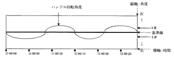
図2は、蛇行運転をした車両におけるハンドルの操舵量の時間的変化の一例を示す図である。
ここで、上述した各パラメータは「5秒ごと」、「5度」、「30秒」、「3回」と設定されている場合に、図2に示す例では、30秒の間に、操舵角によって決定する車輌の進行方向と基準線の方向との角度差が5度以上になった場合が3回あるので蛇行運転であると判定する。
FIG. 2 is a diagram illustrating an example of a temporal change in the steering amount of the steering wheel in the vehicle that has performed the meandering operation.
Here, in the example shown in FIG. 2, when each parameter mentioned above is set to “every 5 seconds”, “5 degrees”, “30 seconds”, and “3 times”, the steering is performed within 30 seconds. Since the angle difference between the vehicle traveling direction determined by the angle and the direction of the reference line is 5 degrees or more, it is determined that the operation is meandering.
居眠り運転は、下記のようにして判定する。
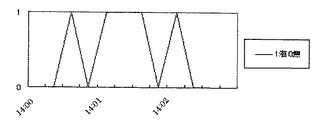
図3は、居眠り運転警告センサの検出結果を示す図である。
車載されている居眠り運転警告センサ2Eの居眠り警告有無のデータに基づき、警告があったか否かを判定し、警告が1回でもあった場合は居眠り運転であると判定する。
警告有無データは、時刻と2数値(フラグ)で持ち、一定時間内に1回でも“1”があれば居眠り運転であると判定する。
Dozing is determined as follows.
FIG. 3 is a diagram illustrating a detection result of the drowsy driving warning sensor.
It is determined whether or not there is a warning based on the data on the presence or absence of a dozing warning of the dozing operation warning sensor 2E mounted on the vehicle. If there is even one warning, it is determined that the operation is a dozing operation.
The warning presence / absence data has a time and two numerical values (flags), and if “1” is present even once within a fixed time, it is determined that the operation is a snoozing operation.
図4は、本発明の車輌運転状況監視システムにおける車輌運転状況監視サーバ内における処理手順を示すフローチャートである。
まず、ステップS1でデータベース12Eから運転状況データを読み込む。具体的には、車速、アクセル開度、ブレーキペダルの踏み込み量、ハンドルの操舵量、及び居眠り警告センサ2Eの発報の有無を読み込む。
なお、このとき運転状況解析手段12Bは、所定時間毎にデータベース12Eから運転状況データを読み込んで運転状況データを読み込むと共に、車輌位置解析手段12Cの解析結果(時系列的な車輌位置データ)をデータベース12Eから読み込む。
FIG. 4 is a flowchart showing a processing procedure in the vehicle driving situation monitoring server in the vehicle driving situation monitoring system of the present invention.
First, operation status data is read from the database 12E in step S1. Specifically, the vehicle speed, the accelerator opening, the amount of depression of the brake pedal, the steering amount of the steering wheel, and the presence / absence of the alarm of the dozing warning sensor 2E are read.
At this time, the driving situation analyzing means 12B reads the driving situation data from the database 12E every predetermined time and reads the driving situation data, and the analysis result (time-series vehicle position data) of the vehicle position analyzing means 12C is stored in the database. Read from 12E.
次に、速度超過(ステップS2〜S4)、急発進(ステップS5〜S7)、急ブレーキ(ステップS8〜S10)、蛇行運転(ステップS11〜S13)及び居眠り運転(ステップS14〜S16)を並列的に判定する。 Next, overspeed (steps S2 to S4), sudden start (steps S5 to S7), sudden braking (steps S8 to S10), meandering operation (steps S11 to S13) and dozing operation (steps S14 to S16) are performed in parallel. Judgment.
速度超過の判定を行う初めのステップS2では、車速データを取得したかを判定する。取得した場合は、フローはステップS3に進行し、速度超過があったか否かを判定する。
具体的には、車輌位置データに基づいて各時刻において車輌が走行していた道路の法定速度と、各時刻における車輌の速度とを比較し、所定時間以上にわたって所定速度以上法定速度を超過していたか否かを判定する。
速度超過があったと判定した場合は、フローはステップS4に進行し、異常内容送信手段12Dによって速度超過の警告が車輌のIDと共にクライアント端末13に送信される。
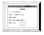
クライアント端末13のモニタには、図5に示すように速度超過を示すウィンドウが表示される。
なお、ステップS2及びS3において、それぞれ「No」と判定した場合は、フローはリターンする。
In the first step S2 for determining whether or not the speed is exceeded, it is determined whether or not vehicle speed data has been acquired. If acquired, the flow proceeds to step S3, where it is determined whether or not there is an excess of speed.
Specifically, the legal speed of the road on which the vehicle was traveling at each time based on the vehicle position data was compared with the vehicle speed at each time, and the legal speed exceeded the predetermined speed over a predetermined time. It is determined whether or not.
If it is determined that there has been an overspeed, the flow proceeds to step S4, and an abnormal content transmission means 12D transmits an overspeed warning to the
On the monitor of the
If it is determined “No” in steps S2 and S3, the flow returns.
急発進の判定を行う初めのステップS5では、アクセル開度データを取得したかを判定する。取得した場合は、フローはステップS6に進行し、車速が所定値以下の時刻におけるアクセル開度の時間的変化が所定値以上であったときがあるかを判定する。
あると判定した場合は、ステップS7において異常内容送信手段12Dによって急発進の警告が車輌のIDと共にクライアント端末13に送信される。
なお、ステップS5及びS6において、それぞれ「No」と判定した場合は、フローはリターンする。
In the first step S5 for determining the sudden start, it is determined whether the accelerator opening degree data has been acquired. If acquired, the flow proceeds to step S6, and it is determined whether or not there is a case where the temporal change in the accelerator opening at the time when the vehicle speed is equal to or less than a predetermined value is greater than or equal to the predetermined value.
If it is determined that there is, a warning of sudden start is transmitted to the
If it is determined “No” in steps S5 and S6, the flow returns.
急ブレーキの判定を行う初めのステップS8では、ブレーキペダルの踏み込み量データを取得したかを判定する。取得した場合は、フローはステップS9に進行し、ブレーキペダルの踏み込み量の時間的変化が所定値以上であったときがあるかを判定する。
ブレーキペダルの踏み込み量の時間的変化が所定値以上であったときがあると判定した場合は、ステップS10において異常内容送信手段12Dによって急ブレーキの警告が車輌のIDと共にクライアント端末13に送信される。
なお、ステップS8及びS9において、それぞれ「No」と判定した場合は、フローはリターンする。
In the first step S8 for determining sudden braking, it is determined whether or not brake pedal depression amount data has been acquired. If acquired, the flow proceeds to step S9, and it is determined whether the temporal change in the amount of depression of the brake pedal may be a predetermined value or more.
If it is determined that the temporal change in the amount of depression of the brake pedal is greater than or equal to a predetermined value, a sudden brake warning is transmitted to the
If it is determined “No” in steps S8 and S9, the flow returns.
蛇行運転の判定を行う初めのステップS11では、操舵量データを取得したかを判定する。取得した場合は、フローはステップS12に進行し、2地点間における操舵量を参照し、操舵角によって決定する車輌の進行方向と基準線の方向との角度差が所定角度以上であり、かつ、この状態が所定時間内に所定回数以上繰り返し行われた場合があったかを判定する。
所定角度以上であり、かつ、この状態が所定時間内に所定回数以上繰り返し行われた場合があると判定した場合は、ステップS13において異常内容送信手段12Dによって蛇行運転の警告が車輌のIDと共にクライアント端末13に送信される。
なお、ステップS11及びS12において、それぞれ「No」と判定した場合は、フローはリターンする。
In the first step S11 for determining the meandering operation, it is determined whether or not the steering amount data has been acquired. If acquired, the flow proceeds to step S12, the steering amount between the two points is referred to, the angle difference between the traveling direction of the vehicle determined by the steering angle and the direction of the reference line is a predetermined angle or more, and It is determined whether or not this state has been repeated a predetermined number of times within a predetermined time.
If it is determined that the angle is equal to or greater than the predetermined angle and this state has been repeatedly performed a predetermined number of times within a predetermined time, the abnormal content transmitting means 12D sends a warning about the meandering operation together with the vehicle ID in step S13. It is transmitted to the terminal 13.
If it is determined “No” in steps S11 and S12, the flow returns.
居眠り運転の判定を行う初めのステップS14では、居眠り運転信号を取得したかを判定する。取得した場合はフローはステップS15に進行し、居眠り運転警告センサの居眠り警告有無のデータに基づき、警告があったか否かを判定し、警告が1度でもあったかを判定する。警告有無データは、時刻と2数値(フラグ)で持ち、一定時間内に1回でも“1”があれば居眠り運転であると判定する。
居眠り運転を示すフラグがあった場合は、フローはステップS16に進行し、異常内容送信手段12Dによって居眠り運転の警告が車輌のIDと共にクライアント端末13に送信される。
なお、ステップS14及びS15において、それぞれ「No」と判定した場合は、フローはリターンする。
In the first step S14 in which the determination of a dozing operation is performed, it is determined whether a dozing operation signal has been acquired. If acquired, the flow proceeds to step S15, where it is determined whether or not there is a warning based on the data on the presence or absence of the drowsiness warning of the dozing operation warning sensor, and whether or not the warning has occurred once. The warning presence / absence data has a time and two numerical values (flags), and if “1” is present even once within a fixed time, it is determined that the operation is a snoozing operation.
If there is a flag indicating doze driving, the flow proceeds to step S16, and a warning of dozing operation is transmitted to the
If it is determined “No” in steps S14 and S15, the flow returns.
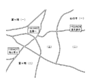
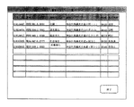
なお、速度超過、急発進、急ブレーキ、蛇行運転及び居眠り運転の判定結果を図6に示すように、地図上に示した形でクライアント端末13のモニタに表示させてもよく、また、図7に示すように表形式にしてクライアント端末13のモニタに表示させてもよい。さらに、このような地図上に示したデータや表形式のデータを車両運転状況監視サーバ12のデータベース12Eに登録し、一定期間毎にクライアントに報告するようにしてもよい。
Note that the determination results of overspeed, sudden start, sudden braking, meandering operation and dozing operation may be displayed on the monitor of the
以上、本発明の車輌運転状況監視システムによれば、車輌の運転中にリアルタイムでデータを送信して車両運転状況監視サーバで解析を行い、危険運転が判明した場合に直ちに注意通知を発信することや警察に通報することにより、速度違反、居眠り運転や飲酒運転による交通事故を未然に防ぐ確率を高めることができる。
また、特に、速度超過、急発進、急ブレーキ、蛇行運転及び居眠り運転の有無を判定してクライアント端末13に送付するので、車輌の管理者側で車輌の運転状況をリアルタイムに把握することができる。
As described above, according to the vehicle driving condition monitoring system of the present invention, data is transmitted in real time during driving of the vehicle, analysis is performed by the vehicle driving condition monitoring server, and a warning notice is immediately transmitted when dangerous driving is found. By reporting to the police, it is possible to increase the probability of preventing traffic accidents due to speed violations, drowsy driving or drunk driving.
In particular, since the presence or absence of overspeed, sudden start, sudden braking, meandering driving and dozing driving is determined and sent to the
1 GPSアンテナ、2 車輌センサ、2A 車速センサ、2B アクセル開度センサ、2C ブレーキセンサ、2D 操舵量センサ、2E 居眠り警告センサ、3 タイマ、4 車載演算装置、4A データ受信部、4B センサデータ受信部、4C 車載通信部、4D メモリ、5 通信端末、10 車輌側システム、11 ネットワーク、12 車輌運転状況監視サーバ、12A データ受信手段、12D 異常内容送信手段、12B 運転状況解析手段、12C 車輌位置解析手段、12E データベース、13 クライアント端末。
DESCRIPTION OF
Claims (3)
前記運転状況データを解析し、運転状況における異常の有無を判定する運転状況解析手段と、
前記運転状況解析手段によって運転状況の異常が判定されると、その異常内容をクライアント端末に送信する異常内容送信手段と
を備える車輌運転状況監視システム。 Driving status data receiving means for receiving vehicle position data, driving status data and time data transmitted from the vehicle side every predetermined time through the network;
Driving state analysis means for analyzing the driving state data and determining the presence or absence of abnormality in the driving state;
A vehicle driving situation monitoring system comprising: an abnormality content transmitting means for transmitting an abnormality content to a client terminal when an abnormality in the driving situation is determined by the driving situation analyzing means.
ネットワークを通じて車輌側から所定時間毎に送信される車輌位置データ、運転状況データ及び時刻データを受信する運転状況データ受信手段、
前記運転状況データを解析し、運転状況における異常の有無を判定する運転状況解析手段、及び、
前記運転状況解析手段によって運転状況の異常が判定されると、その異常内容をクライアント端末に送信する異常内容送信手段
として機能させるための車輌運転状況監視プログラム。 Computer
Driving status data receiving means for receiving vehicle position data, driving status data and time data transmitted from the vehicle side every predetermined time through the network,
Driving status analysis means for analyzing the driving status data and determining whether there is an abnormality in the driving status, and
A vehicle driving situation monitoring program for functioning as an abnormality content transmitting means for transmitting an abnormality content to a client terminal when an abnormality in a driving situation is determined by the driving situation analyzing means.
Priority Applications (1)
| Application Number | Priority Date | Filing Date | Title |
|---|---|---|---|
| JP2004104874A JP2005293032A (en) | 2004-03-31 | 2004-03-31 | Vehicle operation state monitoring system and vehicle operation state monitoring program for this system |
Applications Claiming Priority (1)
| Application Number | Priority Date | Filing Date | Title |
|---|---|---|---|
| JP2004104874A JP2005293032A (en) | 2004-03-31 | 2004-03-31 | Vehicle operation state monitoring system and vehicle operation state monitoring program for this system |
Publications (1)
| Publication Number | Publication Date |
|---|---|
| JP2005293032A true JP2005293032A (en) | 2005-10-20 |
Family
ID=35325922
Family Applications (1)
| Application Number | Title | Priority Date | Filing Date |
|---|---|---|---|
| JP2004104874A Pending JP2005293032A (en) | 2004-03-31 | 2004-03-31 | Vehicle operation state monitoring system and vehicle operation state monitoring program for this system |
Country Status (1)
| Country | Link |
|---|---|
| JP (1) | JP2005293032A (en) |
Cited By (10)
| Publication number | Priority date | Publication date | Assignee | Title |
|---|---|---|---|---|
| JP2008059059A (en) * | 2006-08-29 | 2008-03-13 | Hino Motors Ltd | Portable telephone terminal and program |
| WO2009093726A1 (en) * | 2008-01-22 | 2009-07-30 | Advanced Telecommunications Research Institute International | Dangerous drive preventive intention judgment system and dangerous drive preventive intention judgment method |
| JP2010002993A (en) * | 2008-06-18 | 2010-01-07 | Parama Tec:Kk | Operation monitoring system |
| JP2018116362A (en) * | 2017-01-16 | 2018-07-26 | 株式会社A.R.M.S. | Information processing device, information processing method and information processing program |
| JP2019105929A (en) * | 2017-12-11 | 2019-06-27 | 矢崎エナジーシステム株式会社 | Management system |
| US11341852B2 (en) | 2018-02-26 | 2022-05-24 | Nec Corporation | Dangerous act resolution system, apparatus, method, and program |
| CN115100861A (en) * | 2022-06-22 | 2022-09-23 | 公安部交通管理科学研究所 | Drunk driving vehicle identification method |
| US12027039B2 (en) | 2019-12-30 | 2024-07-02 | Subaru Corporation | Mobility information provision system, server, and vehicle |
| US12046140B2 (en) | 2019-12-30 | 2024-07-23 | Subaru Corporation | Mobility information provision system, server, and vehicle |
| JP7545283B2 (en) | 2019-12-30 | 2024-09-04 | 株式会社Subaru | Mobility information providing system, server device, and vehicle |
Citations (5)
| Publication number | Priority date | Publication date | Assignee | Title |
|---|---|---|---|---|
| JPH1116083A (en) * | 1997-06-23 | 1999-01-22 | Yazaki Corp | Operation management system |
| JP2002042288A (en) * | 2000-07-26 | 2002-02-08 | Yazaki Corp | Running state recording device and running control system using it |
| JP2002225586A (en) * | 2001-02-05 | 2002-08-14 | Nissan Motor Co Ltd | Degree of safety driving recorder for vehicle |
| JP2004021331A (en) * | 2002-06-12 | 2004-01-22 | Yazaki Corp | Vehicle-related information providing system and its method |
| JP2004075023A (en) * | 2002-08-22 | 2004-03-11 | Alpine Electronics Inc | Vehicle information recorder and system thereof |
-
2004
- 2004-03-31 JP JP2004104874A patent/JP2005293032A/en active Pending
Patent Citations (5)
| Publication number | Priority date | Publication date | Assignee | Title |
|---|---|---|---|---|
| JPH1116083A (en) * | 1997-06-23 | 1999-01-22 | Yazaki Corp | Operation management system |
| JP2002042288A (en) * | 2000-07-26 | 2002-02-08 | Yazaki Corp | Running state recording device and running control system using it |
| JP2002225586A (en) * | 2001-02-05 | 2002-08-14 | Nissan Motor Co Ltd | Degree of safety driving recorder for vehicle |
| JP2004021331A (en) * | 2002-06-12 | 2004-01-22 | Yazaki Corp | Vehicle-related information providing system and its method |
| JP2004075023A (en) * | 2002-08-22 | 2004-03-11 | Alpine Electronics Inc | Vehicle information recorder and system thereof |
Cited By (13)
| Publication number | Priority date | Publication date | Assignee | Title |
|---|---|---|---|---|
| JP2008059059A (en) * | 2006-08-29 | 2008-03-13 | Hino Motors Ltd | Portable telephone terminal and program |
| WO2009093726A1 (en) * | 2008-01-22 | 2009-07-30 | Advanced Telecommunications Research Institute International | Dangerous drive preventive intention judgment system and dangerous drive preventive intention judgment method |
| JP2009199583A (en) * | 2008-01-22 | 2009-09-03 | Advanced Telecommunication Research Institute International | Dangerous drive preventive intention judgment system and dangerous drive preventive intention judgment method |
| CN101952868A (en) * | 2008-01-22 | 2011-01-19 | 株式会社国际电气通信基础技术研究所 | Dangerous driving prevention consciousness decision-making system and dangerous driving prevention consciousness decision method |
| JP2010002993A (en) * | 2008-06-18 | 2010-01-07 | Parama Tec:Kk | Operation monitoring system |
| JP2018116362A (en) * | 2017-01-16 | 2018-07-26 | 株式会社A.R.M.S. | Information processing device, information processing method and information processing program |
| JP2019105929A (en) * | 2017-12-11 | 2019-06-27 | 矢崎エナジーシステム株式会社 | Management system |
| JP7107674B2 (en) | 2017-12-11 | 2022-07-27 | 矢崎エナジーシステム株式会社 | management system |
| US11341852B2 (en) | 2018-02-26 | 2022-05-24 | Nec Corporation | Dangerous act resolution system, apparatus, method, and program |
| US12027039B2 (en) | 2019-12-30 | 2024-07-02 | Subaru Corporation | Mobility information provision system, server, and vehicle |
| US12046140B2 (en) | 2019-12-30 | 2024-07-23 | Subaru Corporation | Mobility information provision system, server, and vehicle |
| JP7545283B2 (en) | 2019-12-30 | 2024-09-04 | 株式会社Subaru | Mobility information providing system, server device, and vehicle |
| CN115100861A (en) * | 2022-06-22 | 2022-09-23 | 公安部交通管理科学研究所 | Drunk driving vehicle identification method |
Similar Documents
| Publication | Publication Date | Title |
|---|---|---|
| CN110807930B (en) | Dangerous vehicle early warning method and device | |
| JP5659939B2 (en) | Vehicle detection system, in-vehicle device and center | |
| JP2020135675A (en) | Dangerous driving risk information output system and dangerous driving risk information output program | |
| TWI547913B (en) | Real-time drive assistance system and method | |
| CN111210620B (en) | Method, device and equipment for generating driver portrait and storage medium | |
| GB2522728A (en) | Monitoring device | |
| CN111914237B (en) | Automobile driver biometric authentication and GPS services | |
| JP2008165604A (en) | Alarm system for preventing automobile accident | |
| CN110881166B (en) | Collaborative help calling method and device, wearable device and storage medium | |
| WO2021002368A1 (en) | Safety performance evaluation device, safety performance evaluation method, information processing device, and information processing method | |
| JP2015022499A (en) | Driving characteristic determination system | |
| JP2011238045A (en) | Accident situation recording system | |
| JP2014075035A (en) | Operation support system and in-vehicle unit to be used for the same system | |
| JP2007323281A (en) | Danger occurrence point information collection system, on-vehicle device, and danger occurrence point information collection device | |
| CN111209797A (en) | Method, device, equipment and storage medium for monitoring driving behavior | |
| JP2017167795A (en) | Annoying drive detection device and annoying drive detection method | |
| JP2023067970A (en) | Information processor | |
| JP2020135674A (en) | Traffic risk information output system and traffic risk information output program | |
| JP2005293032A (en) | Vehicle operation state monitoring system and vehicle operation state monitoring program for this system | |
| WO2015188450A1 (en) | Pre-alarm processing method and device | |
| CN111862386A (en) | Accident recording method, device, medium and server for vehicle | |
| CN113352989B (en) | Intelligent driving safety auxiliary method, product, equipment and medium | |
| CN106767859A (en) | A kind of automobile navigation method | |
| JP2014137682A (en) | Traffic information provision system using location information of mobile terminal | |
| CN115348149A (en) | Equipment monitoring method and device in Internet of vehicles and terminal equipment |
Legal Events
| Date | Code | Title | Description |
|---|---|---|---|
| A131 | Notification of reasons for refusal |
Free format text: JAPANESE INTERMEDIATE CODE: A131 Effective date: 20060905 |
|
| A521 | Written amendment |
Free format text: JAPANESE INTERMEDIATE CODE: A523 Effective date: 20061031 |
|
| A02 | Decision of refusal |
Free format text: JAPANESE INTERMEDIATE CODE: A02 Effective date: 20061219 |
