JP2005292990A - Bar code reading apparatus and bar code reading method - Google Patents
Bar code reading apparatus and bar code reading method Download PDFInfo
- Publication number
- JP2005292990A JP2005292990A JP2004104238A JP2004104238A JP2005292990A JP 2005292990 A JP2005292990 A JP 2005292990A JP 2004104238 A JP2004104238 A JP 2004104238A JP 2004104238 A JP2004104238 A JP 2004104238A JP 2005292990 A JP2005292990 A JP 2005292990A
- Authority
- JP
- Japan
- Prior art keywords
- reading
- barcode
- unit
- area sensor
- reflected light
- Prior art date
- Legal status (The legal status is an assumption and is not a legal conclusion. Google has not performed a legal analysis and makes no representation as to the accuracy of the status listed.)
- Pending
Links
Images


Abstract
【課題】 1次元バーコードと2次元バーコードの読取動作を簡単に切り替えることができ、読取動作を高速化できるバーコード読取装置を提供する。
【解決手段】 バーコード読取装置1は、その筐体前面に、表示部10、操作部12および第2の読取開始キー13を有し、筐体両側面に、一対の第1の読取開始キー14を有する。バーコード読取装置1の筐体背面には、読取口15が形成され、この読取口15には、レーザスキャナ17およびエリアセンサ18が配置されている。バーコードを読み取る際、読取対象が1次元バーコードである場合、使用者が第1の読取開始キー14を押下することで、レーザスキャナ17を用いて1次元バーコードを読み取り、2次元バーコードである場合、使用者が第2の読取開始キー13を押下することで、エリアセンサ18を用いて2次元バーコードを読み取る。
【選択図】 図1PROBLEM TO BE SOLVED: To provide a bar code reader capable of easily switching a reading operation of a one-dimensional bar code and a two-dimensional bar code and speeding up the reading operation.
A barcode reader 1 has a display unit 10, an operation unit 12 and a second reading start key 13 on the front surface of the casing, and a pair of first reading start keys on both sides of the casing. 14 A reading port 15 is formed on the rear surface of the casing of the barcode reader 1, and a laser scanner 17 and an area sensor 18 are arranged in the reading port 15. When reading a bar code, if the reading target is a one-dimensional bar code, the user presses the first reading start key 14 to read the one-dimensional bar code using the laser scanner 17 and to read the two-dimensional bar code. In this case, the user presses the second reading start key 13 to read the two-dimensional barcode using the area sensor 18.
[Selection] Figure 1
Description
本発明は、1次元バーコード及び2次元バーコードを読み取り可能なバーコード読取装置及びバーコード読取方法に関する。 The present invention relates to a barcode reading apparatus and a barcode reading method capable of reading a one-dimensional barcode and a two-dimensional barcode.
この種のバーコード読取装置として、従来、特許文献1に記載のものが知られている。このバーコード読取装置は、1次元バーコード読み取り用のレーザスキャナと2次元バーコード読み取り用のエリアセンサとを有し、1次元バーコード及び2次元バーコードを読み取り可能なものである。バーコードの読取動作を開始すると、まず、レーザスキャナによる1次元バーコードの読み取り処理を行い、これによって得られたデジタル信号を解析して1次元バーコードが検出されたか否かを判別し、1次元バーコードが検出されなかった場合、エリアセンサによる2次元バーコードの読み取り処理に移行する。これにより、1次元バーコードであるか2次元バーコードであるかを自動的に判別し、それぞれに適した読取動作を行うことができる。
As this type of barcode reader, a device described in
しかしながら、上記従来例のバーコード読取装置では、レーザスキャナによる1次元バーコードの読み取り処理を所定回数行っても1次元バーコードが検出されなかった場合に限って、エリアセンサによる2次元バーコードの読み取り処理に移行していたので、2次元バーコードの場合は速やかに読取動作を行うことができなかった。一般に、使用者は読取対象のバーコードが1次元であるか2次元であるかを容易に識別できるので、予め2次元バーコードと分かっている場合であっても、2次元バーコードの読取動作に時間がかかるという問題点があった。このため、1次元バーコードと2次元バーコードの読取動作の切り替えが簡単にできると便利である。 However, in the barcode reader of the above-described conventional example, only when the one-dimensional barcode is not detected even if the one-dimensional barcode reading process by the laser scanner is performed a predetermined number of times, the two-dimensional barcode by the area sensor is not detected. Since the process has shifted to the reading process, in the case of the two-dimensional barcode, the reading operation cannot be performed promptly. Generally, since the user can easily identify whether the barcode to be read is one-dimensional or two-dimensional, even when the barcode is known in advance, the reading operation of the two-dimensional barcode is performed. There was a problem that it took time. For this reason, it is convenient if the switching operation of the one-dimensional barcode and the two-dimensional barcode can be easily performed.
また、バーコード読み取り時間の短縮のために、例えばレーザスキャナ及びエリアセンサによる同時読取動作を行おうとした場合、それぞれの読取手段による読取動作を適切に制御して同時読取動作を短時間で行えるようにするための工夫が必要となる。 In order to shorten the barcode reading time, for example, when a simultaneous reading operation by a laser scanner and an area sensor is performed, the reading operation by each reading unit is appropriately controlled so that the simultaneous reading operation can be performed in a short time. It is necessary to devise to make it.
本発明は、上記事情に鑑みてなされたもので、1次元バーコードと2次元バーコードの読取動作を簡単に切り替えることができるバーコード読取装置及びバーコード読取方法を提供することを目的とする。また、本発明は、1次元バーコードと2次元バーコードとを読み取り可能な複数の読取手段による同時読取動作を高速化させることができるバーコード読取装置及びバーコード読取方法を提供することを目的とする。 The present invention has been made in view of the above circumstances, and an object of the present invention is to provide a barcode reading apparatus and a barcode reading method capable of easily switching between reading operations of a one-dimensional barcode and a two-dimensional barcode. . Another object of the present invention is to provide a barcode reading apparatus and a barcode reading method capable of speeding up simultaneous reading operations by a plurality of reading means capable of reading a one-dimensional barcode and a two-dimensional barcode. And
本発明のバーコード読取装置は、バーコード記録面に対して光を走査し、その反射光からバーコードを読み取る第1の読取手段と、前記バーコード記録面の画像を取り込み、取り込まれた画像を解析してバーコードを読み取る第2の読取手段と、前記第1の読取手段による読取動作を開始させる第1の開始指示手段と、前記第2の読取手段による読取動作を開始させる第2の開始指示手段とを備えたものである。 The barcode reader of the present invention scans the barcode recording surface with light, reads the barcode from the reflected light, and captures the image of the barcode recording surface. Second reading means for analyzing the bar code, first start instruction means for starting the reading operation by the first reading means, and second reading means for starting the reading operation by the second reading means Start instruction means.
この構成により、使用者の判断に従って第1あるいは第2の開始指示手段が操作されることによって、第1の読取手段あるいは第2の読取手段の読取動作に簡単に切り替えることができる。したがって、例えば、読み取り対象が1次元バーコードである場合、第1の読取手段だけを動作させることで、その読取処理を高速化させることができ、2次元バーコードである場合、第2の読取手段だけを動作させることで、その読取処理を高速化させることができるため、総合的にバーコードの読取動作を短時間で実行可能となる。 With this configuration, it is possible to easily switch to the reading operation of the first reading unit or the second reading unit by operating the first or second start instruction unit according to the judgment of the user. Therefore, for example, when the reading target is a one-dimensional barcode, the reading process can be speeded up by operating only the first reading means. When the reading target is a two-dimensional barcode, the second reading is performed. By operating only the means, the reading process can be speeded up, so that the barcode reading operation can be comprehensively executed in a short time.
また、本発明の一態様として、上記のバーコード読取装置であって、前記第1の開始指示手段の機能を有する押下自在な第1の操作キーと、前記第2の開始指示手段の機能を有する押下自在な第2の操作キーとを備え、前記第1の操作キーが押下された場合、前記第1の読取手段による読取動作を開始させ、前記第2の操作キーが押下された場合、前記第2の読取手段による読取動作を開始させるものも含まれる。 Further, as one aspect of the present invention, in the barcode reading apparatus described above, the first operation key having a function of the first start instruction unit and the function of the second start instruction unit are provided. A second operation key that can be pressed, and when the first operation key is pressed, the reading operation by the first reading unit is started, and when the second operation key is pressed, Also included is one that starts the reading operation by the second reading means.
この構成により、それぞれの操作キーを押下するだけで、第1の読取手段による読取動作と第2の読取手段による読取動作を簡単に切り替えることができる。 With this configuration, the reading operation by the first reading unit and the reading operation by the second reading unit can be easily switched by simply pressing each operation key.
また、本発明の一態様として、上記のバーコード読取装置であって、前記第1の開始指示手段および前記第2の開始指示手段の機能を有する、第1の押下状態および第2の押下状態の2段階に押下自在な操作キーを備え、前記操作キーの前記第1の押下状態が検出された場合、前記第1の読取手段による読取動作を開始させ、前記操作キーの前記第2の押下状態が検出された場合、前記第2の読取手段による読取動作を開始させるものも含まれる。 Further, as one aspect of the present invention, in the barcode reading apparatus described above, a first pressed state and a second pressed state having functions of the first start instruction unit and the second start instruction unit When the first pressing state of the operation key is detected, a reading operation by the first reading unit is started, and the second pressing of the operation key is performed. When the state is detected, the one that starts the reading operation by the second reading unit is also included.
この構成により、1つの操作キーだけで、第1の読取手段による読取動作と第2の読取手段による読取動作を簡単に切り替えることができる。このため、装置筐体上のキーの配置スペースを削減でき、持ち易くなって使い勝手を向上できる。 With this configuration, the reading operation by the first reading unit and the reading operation by the second reading unit can be easily switched with only one operation key. For this reason, the arrangement space of the keys on the apparatus housing can be reduced, and it is easy to hold and the usability can be improved.
本発明のバーコード読取装置は、バーコード記録面に対して光を走査しながらその反射光のデータを取り込み、取り込まれた反射光のデータを解析してバーコードを読み取る第1の読取手段と、前記バーコード記録面の画像を取り込み、取り込まれた画像のデータを解析してバーコードを読み取る第2の読取手段と、前記第1および第2の読取手段による同時読取動作を開始させる開始指示手段と、前記同時読取動作が開始された場合、前記第1および第2の読取手段による同時読取動作を制御する読取制御手段とを備え、前記読取制御手段は、前記第2の読取手段による画像の取り込み中、前記第1の読取手段による光の走査を停止させる走査停止手段を備え、前記第1の読取手段による読取動作と前記第2の読取手段による読取動作とを重複させずに行うように制御するものである。 The bar code reader of the present invention includes first reading means for reading the reflected light data while scanning the bar code recording surface, analyzing the captured reflected light data, and reading the bar code. , A second reading unit that captures an image of the barcode recording surface, analyzes the data of the captured image and reads the barcode, and a start instruction to start the simultaneous reading operation by the first and second reading units And a reading control means for controlling the simultaneous reading operation by the first and second reading means when the simultaneous reading operation is started, wherein the reading control means is an image by the second reading means. Scanning stop means for stopping the scanning of light by the first reading means during reading, and reading operation by the first reading means and reading operation by the second reading means And controls to perform without double.
この構成により、第1の読取手段および第2の読取手段による同時読取動作を行い、バーコード読取動作を高速化させることができる。このとき、例えば、第1の読取手段および第2の読取手段による読取動作のうち、早く結果が出た方を採用することで、バーコードの違いによる読取時間の差を減らすことができ、全体としての読取動作を高速化させることができる。このように、第1の読取手段および第2の読取手段による読取動作を効率良く同時に行うことで、これらの読取処理を短時間で実行することができる。また、第2の読取手段による画像の取り込み中、第1の読取手段による光の走査を停止させることで、第1の読取手段による反射光の影響を避けることができ、第2の読取手段によって取り込まれる画像の画質を高めることができるため、結果としてバーコード読取処理を短時間で実行できる。 With this configuration, the simultaneous reading operation by the first reading unit and the second reading unit can be performed, and the barcode reading operation can be speeded up. At this time, for example, it is possible to reduce the difference in the reading time due to the difference in the bar code by adopting the faster one of the reading operations by the first reading unit and the second reading unit. The reading operation can be speeded up. In this way, by performing the reading operation by the first reading unit and the second reading unit efficiently and simultaneously, these reading processes can be executed in a short time. Further, by stopping the scanning of the light by the first reading unit during the image capturing by the second reading unit, the influence of the reflected light by the first reading unit can be avoided. Since the quality of the captured image can be improved, the barcode reading process can be executed in a short time as a result.
また、本発明の一態様として、上記のバーコード読取装置であって、前記読取制御手段は、前記第2の読取手段による今回の画像の取り込みから次回の画像の取り込みまでの間に、前記第1の読取手段による反射光のデータの取り込みおよびこの反射光のデータの解析を連続して行うものも含まれる。 Further, as one aspect of the present invention, in the barcode reading apparatus described above, the reading control unit may perform the first reading from the current image capturing by the second reading unit until the next image capturing. Also included is one that continuously captures reflected light data and analyzes the reflected light data by one reading means.
この構成により、第1の読取手段および第2の読取手段による同時読取動作を行う際、データ解析等の処理を効率良く行うことができる。 With this configuration, when performing the simultaneous reading operation by the first reading unit and the second reading unit, processing such as data analysis can be performed efficiently.
また、本発明の一態様として、上記のバーコード読取装置であって、前記読取制御手段は、前記第2の読取手段による今回の画像の取り込み後、前記第1の読取手段による反射光のデータの取り込みを繰り返し、前記第2の読取手段による次回の画像の取り込み中、前記第1の読取手段により繰り返し取り込まれた反射光のデータをまとめて解析するものも含まれる。 According to another aspect of the present invention, in the barcode reading apparatus described above, the reading control unit may receive reflected light data from the first reading unit after capturing the current image by the second reading unit. And the reflected light data repeatedly captured by the first reading unit during the next image capturing by the second reading unit are included.
この構成により、第1の読取手段および第2の読取手段による同時読取動作を行う際、第2の読取手段による読取動作を早くすることができる。 With this configuration, when the simultaneous reading operation by the first reading unit and the second reading unit is performed, the reading operation by the second reading unit can be accelerated.
また、本発明の一態様として、上記のバーコード読取装置であって、前記読取制御手段は、前記第1および第2の読取手段による同時読取動作を時分割に制御するものも含まれる。 Further, as one aspect of the present invention, the above-described barcode reading apparatus, wherein the reading control unit controls a simultaneous reading operation by the first and second reading units in a time division manner.
この構成により、プロセッサ等の処理部の構成を簡略化することが可能となる。
また、本発明の一態様として、上記のバーコード読取装置であって、前記第1の読取手段によって取り込まれる反射光のデータは、DMA転送により、プロセッサに接続されるバスを介してメモリに記憶されるものも含まれる。
With this configuration, the configuration of a processing unit such as a processor can be simplified.
Further, as one aspect of the present invention, in the barcode reading apparatus described above, the reflected light data captured by the first reading unit is stored in a memory via a bus connected to the processor by DMA transfer. Is included.
この構成により、プロセッサの負荷を軽減でき、バーコード読取動作の高速化を図ることができる。 With this configuration, the load on the processor can be reduced and the barcode reading operation can be speeded up.
また、本発明の一態様として、上記のバーコード読取装置であって、前記第1の読取手段によって取り込まれる反射光のデータおよび前記第2の読取手段によって取り込まれる画像のデータは、DMA転送により、プロセッサに接続されるバスを介してメモリに記憶されるものも含まれる。 According to another aspect of the present invention, in the barcode reading apparatus described above, the reflected light data captured by the first reading unit and the image data captured by the second reading unit are transferred by DMA transfer. Also included are those stored in memory via a bus connected to the processor.
この構成により、より一層、プロセッサの負荷を軽減でき、バーコード読取動作の高速化を図ることができる。 With this configuration, it is possible to further reduce the load on the processor and increase the speed of the barcode reading operation.
また、本発明の一態様として、上記のバーコード読取装置であって、前記第1の読取手段によって取り込まれる反射光のデータおよび前記第2の読取手段によって取り込まれる画像のデータは、それぞれ前記第1の読取手段および前記第2の読取手段に設けられたバッファメモリに記憶されるものも含まれる。 Further, as one aspect of the present invention, in the above barcode reader, the reflected light data captured by the first reading unit and the image data captured by the second reading unit are Those stored in a buffer memory provided in one reading means and the second reading means are also included.
この構成により、データ転送時間を省くことができ、より一層高速化を図ることができる。 With this configuration, the data transfer time can be saved and the speed can be further increased.
本発明のバーコード読取方法は、バーコード記録面に対して光を走査しながらその反射光のデータを取り込み、取り込まれた反射光のデータを解析してバーコードを読み取る第1の読取ステップと、前記バーコード記録面の画像を取り込み、取り込まれた画像のデータを解析してバーコードを読み取る第2の読取ステップと、操作入力に応じて前記第1および第2の読取手段による同時読取動作を開始させる読取開始ステップと、前記同時読取動作が開始された場合、前記第1および第2の読取ステップによる同時読取動作を制御する読取制御ステップとを有し、前記読取制御ステップにおいて、前記第2の読取ステップによる画像の取り込み中、前記第1の読取ステップによる光の走査を停止させる走査停止ステップを有し、前記第1の読取ステップによる読取動作と前記第2の読取ステップによる読取動作とを重複させずに行うように制御するものである。 The barcode reading method according to the present invention includes a first reading step of reading the reflected light data while scanning the barcode recording surface while analyzing the captured reflected light data and reading the barcode. , A second reading step for reading an image of the bar code recording surface, analyzing the data of the acquired image and reading the bar code, and a simultaneous reading operation by the first and second reading means in response to an operation input And a reading control step for controlling a simultaneous reading operation by the first and second reading steps when the simultaneous reading operation is started. In the reading control step, A scanning stop step for stopping the scanning of light by the first reading step during capturing of the image by the second reading step, A reading operation by the operation and the second reading step reading by step and controls to perform without overlap.
この手順により、第1の読取手段および第2の読取手段による同時読取動作を効率良く行い、バーコード読取動作を高速化させることができる。 By this procedure, the simultaneous reading operation by the first reading unit and the second reading unit can be efficiently performed, and the barcode reading operation can be speeded up.
本発明によれば、1次元バーコードと2次元バーコードの読取動作を簡単に切り替えることができるバーコード読取装置及びバーコード読取方法を提供可能である。また、1次元バーコードと2次元バーコードとを読み取り可能な複数の読取手段による同時読取動作を高速化させることができるバーコード読取装置及びバーコード読取方法を提供可能である。 According to the present invention, it is possible to provide a barcode reading apparatus and a barcode reading method that can easily switch between reading operations of a one-dimensional barcode and a two-dimensional barcode. Further, it is possible to provide a barcode reading apparatus and a barcode reading method capable of speeding up the simultaneous reading operation by a plurality of reading means capable of reading a one-dimensional barcode and a two-dimensional barcode.
(第1の実施形態)
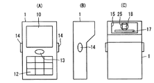
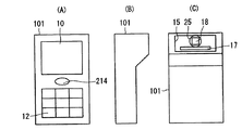
図1は第1の実施形態におけるバーコード読取装置の外観構成を示す図である。図1(A)はバーコード読取装置の正面図、図1(B)はその側面図、図1(C)はその背面図である。バーコード読取装置1の筐体前面には、表示部10、操作部12および第2の読取開始キー13が設けられており、その筐体の両側面には、一対の第1の読取開始キー14が設けられている。また、バーコード読取装置1の筐体背面には、読取口15が形成されており、この読取口15には、レーザスキャナ17およびエリアセンサ18が配置されている。
(First embodiment)
FIG. 1 is a diagram showing an external configuration of a bar code reader according to the first embodiment. 1A is a front view of the barcode reader, FIG. 1B is a side view thereof, and FIG. 1C is a rear view thereof. A
レーザスキャナ17は、第1の読取手段の一例に相当するもので、レーザ発光部およびレーザ受光部を有し、レーザ発光部によって走査されるレーザ光が読取対象であるバーコード記録面で反射されると、レーザ受光部がその反射光を受光し、光電変換を行った後、反射光のデータとしてデジタル信号を出力する。エリアセンサ18は、第2の読取手段の一例に相当するもので、その前面に設けられたレンズ25を介して読取対象であるバーコード記録面の画像を撮影し、その画像データとしてデジタル信号を出力する。このエリアセンサには、平面上に複数の受光部が配置された例えば30万画素程度のCCDセンサやCMOSセンサが用いられる。一般に、レーザスキャナは、読取対象であるバーコード記録面に対し、読み取り角度、読み取り深度および読み取り分解能の点で優れており、エリアセンサに比べて読取時間が短い。一方、レーザスキャナを用いた場合、1次元バーコードしか読み取ることができないが、エリアセンサを用いた場合には、1次元バーコードおよび2次元バーコードのいずれも読み取ることが可能である。
The
表示部10は、液晶表示パネル等から構成されており、各種設定情報の他、読み取られたバーコードの解析結果等を表示する。操作部12は、各種設定を行うためのテンキーや電源オンオフキーを有する。また、一対の第1の読取開始キー14は、第1の開始指示手段および第1の操作キーの一例に相当し、左右どちらか一方のキーが押下されることで、レーザスキャナ17による読取動作の開始を指示するものである。第2の読取開始キー13は、第2の開始指示手段および第2の操作キーの一例に相当し、押下されることで、エリアセンサ18による読取動作の開始を指示するものである。
The
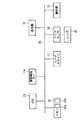
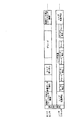
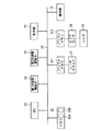
図2は第1の実施形態におけるバーコード読取装置の電気的構成を示すブロック図である。バーコード読取装置1は、CPU(プロセッサ)21、メモリ22の他、前述した第1の読取開始キー14、第2の読取開始キー13、レーザスキャナ17、エリアセンサ18、表示部10、操作部12等がバス24を介して接続された構成を有する。メモリ22は、ROM22aおよびRAM22bからなる。ROM22aには、CPU21によって実行されるバーコード読取用の制御プログラムが格納されている。RAM22bは、CPU21が制御プログラムを実行する際の作業領域として使用される他、画像メモリとして使用され、レーザスキャナ17およびエリアセンサ18から出力されるデジタル信号がRAM22bに記憶される。
FIG. 2 is a block diagram showing an electrical configuration of the barcode reader according to the first embodiment. The
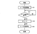
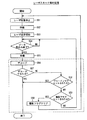
上記構成を有するバーコード読取装置のバーコード読取動作を示す。図3は第1の実施形態におけるバーコード読取動作処理手順を示すフローチャートである。この処理プログラムは、前述したようにROM22aに格納されており、電源オン後、CPU21によって実行される。まず、操作部12の各種キー、第1の読取開始キー14および第2の読取開始キー13のいずれかのキーが押下されるのを待つ(ステップS1)。いずれかのキーが押下されると、押下されたキーが第1の読取開始キー14であるか否かを判別する(ステップS2)。第1の読取開始キー14である場合、レーザスキャナ17によるバーコード読取動作を行う(ステップS3)。この後、本処理を終了する。このバーコード読取動作処理については後述する。
The barcode reading operation of the barcode reading apparatus having the above-described configuration will be described. FIG. 3 is a flowchart showing a barcode reading operation processing procedure in the first embodiment. As described above, this processing program is stored in the
一方、ステップS2で第1の読取開始キー14でない場合、第2の読取開始キー13であるか否かを判別する(ステップS4)。第2の読取開始キー13である場合、エリアセンサ18によるバーコード読取動作を行う(ステップS5)。この後、本処理を終了する。このバーコード読取動作処理については後述する。また一方、ステップS4で第2の読取開始キー13でない場合、操作部12の各種キーが押下されたとして、押下された各種キーに応じたその他の処理を行う(ステップS6)。この後、本処理を終了する。ここで、その他の処理としては、例えば、電源オン後の初期設定、各種読取条件の変更などが挙げられる。
On the other hand, if it is not the first reading start key 14 in step S2, it is determined whether or not it is the second reading start key 13 (step S4). If it is the second reading start key 13, the barcode reading operation by the
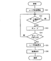
図4はステップS3におけるレーザスキャナ17によるバーコード読取動作処理手順を示すフローチャートである。まず、レーザ走査を開始する(ステップS11)。このレーザ走査が開始されると、レーザ発光部から発せられたレーザ光をバーコード記録面に対して順次走査し、バーコード記録面で反射されたレーザ光を受光し、光電変換を行った後、反射光のデータとしてデジタル信号を出力する。この出力されるデジタル信号は、CPU21によりメモリ22内のRAM22bに順次転送、記憶される。
FIG. 4 is a flowchart showing a barcode reading operation processing procedure by the
RAM22bに1走査分のデジタル信号が取り込まれるのを待ち(ステップS12)、1走査分のデジタル信号が取り込まれると、RAM22bに記憶されたデジタルデータのデコード処理を行う(ステップS13)。そして、デコード処理を行った結果、デコード処理が正常に行われたか否か、つまり1次元バーコードが検出されたか否かを判別する(ステップS14)。デコード処理が正常に行われなかった場合、ステップS12に戻り、同様の処理を繰り返す。一方、ステップS14でデコード処理が正常に行われた場合、レーザ走査を停止する(ステップS15)。この後、デコード処理の結果を表示部10に表示し(ステップS16)、本処理を終了してメインの処理に復帰する。なお、ステップS14で繰り返しデコード処理が正常に行われなかった場合、一定時間の経過をもって本処理を終了するか、使用者が第1の読取開始キー14を離すことにより、割込処理が発生して本処理は強制的に終了する。
Waiting for the digital signal for one scan to be taken into the
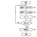
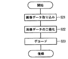
図5はステップS5におけるエリアセンサ18によるバーコード読取動作処理手順を示すフローチャートである。まず、画像データの取込動作を行う(ステップS21)。この画像データの取込動作では、エリアセンサ18が、バーコード記録面の画像を撮影すると、CPU21は、エリアセンサ18からその画像データを読み出し、メモリ22内のRAM22bに順次書き込む。
FIG. 5 is a flowchart showing the barcode reading operation processing procedure by the
そして、RAM22bに記憶された1面分の画像データの各画素値を所定のしきい値と比較して二値化処理を行い(ステップS22)、二値化された画像データに対してデコード処理を行う(ステップS23)。そして、デコード処理を行った結果、デコード処理が正常に行われたか否か、つまり2次元バーコードが検出されたか否かを判別する(ステップS24)。デコード処理が正常に行われなかった場合、ステップS21に戻り、同様の処理を繰り返す。一方、ステップS24でデコード処理が正常に行われた場合、デコード処理の結果を表示部10に表示し(ステップS25)、本処理を終了してメインの処理に復帰する。ここで、ステップS23におけるデコード処理は、1次元バーコードおよび2次元バーコードの両方に対して行われる。なお、ステップS24で繰り返しデコード処理が正常に行われなかった場合、一定時間の経過をもって本処理を終了するか、使用者が第2の読取開始キー13を離すことにより、割込処理が発生して本処理は強制的に終了する。
Then, each pixel value of the image data for one surface stored in the
なお、使用者によって第1の読取開始キー14および第2の読取開始キー13の両方が押されてしまった場合、例えば、先に押下された方のキーによるバーコード読取動作が開始されるようにすればよい。あるいは、この場合は操作が無効であるとしてバーコード読取動作を中止するようにしてもよい。 If the user presses both the first reading start key 14 and the second reading start key 13, for example, the barcode reading operation by the key pressed first is started. You can do it. Alternatively, in this case, the barcode reading operation may be stopped because the operation is invalid.
この第1の実施形態のバーコード読取装置では、読取対象が1次元バーコードである場合、使用者が第1の読取開始キー14を押下することで、速やかに1次元バーコードを読み取ることができる。また、2次元バーコードである場合、使用者が第2の読取開始キー13を押下することで、速やかに2次元バーコードを読み取ることができる。したがって、レーザスキャナ17による読取動作とエリアセンサ18による読取動作とを読取開始キーの選択によって簡単に切り替えることが可能であり、それぞれの読取動作を迅速に実行することができるため、1次元バーコードおよび2次元バーコード両方の読取動作を高速化させることができる。
In the barcode reading apparatus according to the first embodiment, when the reading target is a one-dimensional barcode, the user can quickly read the one-dimensional barcode by pressing the first reading start key 14. it can. If the barcode is a two-dimensional barcode, the user can quickly read the two-dimensional barcode by pressing the second reading start key 13. Accordingly, it is possible to easily switch between the reading operation by the
(第2の実施形態)
図6は第2の実施形態におけるバーコード読取装置の外観構成を示す図である。図6(A)はバーコード読取装置の正面図、図6(B)はその側面図、図6(C)はその背面図である。前記第1の実施形態と同一の構成要素については、同一の符号を用いている。
(Second Embodiment)
FIG. 6 is a diagram showing an external configuration of the barcode reader according to the second embodiment. 6A is a front view of the barcode reader, FIG. 6B is a side view thereof, and FIG. 6C is a rear view thereof. The same reference numerals are used for the same components as those in the first embodiment.
バーコード読取装置101の筐体前面には、表示部10、操作部12および一つの読取開始キー114が設けられている。読取開始キー114は、第1および第2の開始指示手段の機能を有する操作キーの一例に相当し、2段階に押圧状態を検出可能であり、第1の押下状態(1段階目の半押し状態)と第2の押下状態(2段階目の全押し状態)とを出力し、レーザスキャナ17による読取動作の開始とエリアセンサ18による読取動作の開始とをそれぞれ指示するものである。また、バーコード読取装置101の筐体背面には、前記第1の実施形態と同様、読取口15が形成されており、この読取口15には、レーザスキャナ17およびエリアセンサ18が配置されている。
A
図7は第2の実施形態におけるバーコード読取装置の電気的構成を示すブロック図である。このバーコード読取装置101では、CPU21に接続されるバス24には、前記第1の実施形態における第1、第2の読取開始キーの代わりに、読取開始キー114が接続されており、読取開始キー114で検出される第1の押下状態(半押し状態)および第2の押下状態(全押し状態)は、バス24を介してCPU21に伝達される。その他の構成は、前記第1の実施形態と同じである。
FIG. 7 is a block diagram showing an electrical configuration of the barcode reader according to the second embodiment. In this
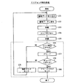
図8は第2の実施形態におけるバーコード読取動作処理手順を示すフローチャートである。この処理プログラムは、前述したようにROM22aに格納されており、電源オン後、CPU21によって実行される。まず、操作部12の各種キーおよび読取開始キー114のいずれかのキーが押下されるのを待つ(ステップS31)。
FIG. 8 is a flowchart showing a barcode reading operation processing procedure in the second embodiment. As described above, this processing program is stored in the
キーが押下されると、押下されたキーが読取開始キー114であるか否かを判別する(ステップS32)。読取開始キー114である場合、読取開始キー114が半押し状態であるか全押し状態であるかを判定するため、所定時間待機する(ステップS33)。そして、半押し状態であるか否かを判別し(ステップS34)、半押し状態である場合、レーザスキャナ17によるバーコード読取動作を行う(ステップS35)。このレーザスキャナ17によるバーコード読取動作は、図9に示す手順により行われる。すなわち、レーザスキャナ17によってレーザ走査を開始し(ステップS11)、バーコードを走査して得られた1走査分のデータ読込みが終了するのを待ち(ステップS12)、データ読込みが終了すると、読み込んだデジタルデータのデコード処理を行う(ステップS13)。そして、デコード処理が終了すると、レーザ走査を停止し(ステップS15)、本処理を終了してメインの処理に復帰する。レーザスキャナ17によるバーコード読取動作の後、バーコードを読み取ることができたか否かを判別する(ステップS36)。バーコードを読み取ることができた場合、本処理を終了する。一方、バーコードを読み取ることができなかった場合、読取開始キー114が離されたか否かを判別する(ステップS37)。読取開始キー114が離された場合、本処理を終了する。一方、読取開始キー114が離されなかった場合、ステップS34に戻って、同様の処理を行う。
When the key is pressed, it is determined whether or not the pressed key is the reading start key 114 (step S32). If it is the reading start key 114, it waits for a predetermined time in order to determine whether the reading start key 114 is half pressed or fully pressed (step S33). Then, it is determined whether or not it is half-pressed (step S34). If it is half-pressed, a barcode reading operation by the
一方、ステップS34で読取開始キー114が全押し状態であると判別された場合、エリアセンサ18によるバーコード読取動作を行う(ステップS38)。このエリアセンサ18によるバーコード読取動作は、図10に示す手順により行われる。すなわち、エリアセンサ18によって画像データの取込動作を行い(ステップS21)、バーコードを撮影して得られた1面分の画像データの各画素値を所定のしきい値と比較して二値化処理を行う(ステップS22)。そして、二値化された画像データに対してデコード処理を行い(ステップS23)、デコード処理が終了すると、本処理を終了してメインの処理に復帰する。エリアセンサ18によるバーコード読取動作の後、バーコードを読み取ることができたか否かを判別する(ステップS39)。バーコードを読み取ることができた場合、本処理を終了する。一方、バーコードを読み取ることができなかった場合、ステップS37の処理に移行し、同様の処理を行う。
On the other hand, if it is determined in step S34 that the reading start key 114 is fully pressed, the barcode reading operation by the
この第2の実施形態のバーコード読取装置では、前記第1の実施形態と同様、1次元バーコードおよび2次元バーコードの読取動作を高速化させることができる。また、1つの読取開始キー114だけで、レーザスキャナ17によるバーコード読取動作とエリアセンサ18によるバーコード読取動作との両方の読取動作の開始を切り替えて指示できる。 このため、操作が容易であり、また、筐体上のキーの配置スペースを削減でき、持ち易くなって使い勝手を向上できる。
In the barcode reader according to the second embodiment, the reading operation of the one-dimensional barcode and the two-dimensional barcode can be speeded up as in the first embodiment. Further, only one reading start key 114 can be used to switch and start the reading operation of both the barcode reading operation by the
(第3の実施形態)
第3の実施形態におけるバーコード読取装置は、レーザスキャナによるバーコード読取動作とエリアセンサによるバーコード読取動作とを同時に行うものである。図11は第3の実施形態におけるバーコード読取装置の外観構成を示す図である。図11(A)はバーコード読取装置の正面図、図11(B)はその側面図、図11(C)はその背面図である。前記第1、第2の実施形態と同一の構成要素については、同一の符号を用いている。
(Third embodiment)
The barcode reading apparatus in the third embodiment simultaneously performs a barcode reading operation by a laser scanner and a barcode reading operation by an area sensor. FIG. 11 is a diagram illustrating an external configuration of a barcode reading apparatus according to the third embodiment. 11A is a front view of the barcode reader, FIG. 11B is a side view thereof, and FIG. 11C is a rear view thereof. The same reference numerals are used for the same components as those in the first and second embodiments.
バーコード読取装置1の筐体前面には、表示部10、操作部12および読取開始キー214が設けられている。また、バーコード読取装置1の筐体背面には、読取口15が形成されており、この読取口15には、レーザスキャナ17およびエリアセンサ18が配置されている。
A
表示部10は、液晶表示パネル等から構成されており、各種設定情報の他、読み取られたバーコードの解析結果等を表示する。操作部12は、各種設定を行うためのテンキーや電源オンオフキーを有する。また、読取開始キー214は、開始指示手段の一例に相当し、単純にオン、オフの入力を行うものであり、レーザスキャナ17によるバーコード読取動作およびエリアセンサ18によるバーコード読取動作の同時開始を指示する。
The
図12は第3の実施形態におけるバーコード読取装置の電気的構成を示すブロック図である。バーコード読取装置1は、CPU(プロセッサ)21、メモリ22、DMAコントローラ19の他、前述した読取開始キー214、レーザスキャナ17、エリアセンサ18、表示部10、操作部12等がバス24を介して接続された構成を有する。メモリ22はROM22aおよびRAM22bからなる。ROM22aには、CPU21によって実行されるバーコード読取用の制御プログラムが格納されている。この制御プログラムを実行するCPU21およびメモリ22等により読取制御手段の機能が実現される。CPU21は、RAM22bに記憶されたデジタル信号がエリアセンサ18から出力された画像データである場合、画像データの二値化処理、コードの切り出し処理およびデコード処理を行い、RAM22bに記憶されたデジタル信号がレーザスキャナ17から出力されたデジタルデータである場合、デコード処理を行う。
FIG. 12 is a block diagram showing an electrical configuration of the barcode reader according to the third embodiment. The
RAM22bは、CPU21が制御プログラムを実行する際の作業領域として使用される他、画像メモリとして使用され、RAM22bには、レーザスキャナ17およびエリアセンサ18から出力されるデジタル信号が記憶される。本実施形態では、レーザスキャナ17から出力されるデジタル信号は、DMAコントローラ19によりRAM22bにDMA転送されて記憶されるが、エリアセンサ18からの画像データは、CPU21によるデータの読み書き動作によりRAM22bに記憶される。また、RAM22bには、エリアセンサ18による撮像を行う場合に値1にセットされる撮像フラグ、およびエリアセンサ18によるデコード処理がOKである場合に値1にセットされるデコードフラグが設定されている。
The
図13は第3の実施形態におけるレーザスキャナによるバーコード読取動作およびエリアセンサによるバーコード読取動作を同時に行う際のタイミングチャートである。本実施形態では、CPU21はタイムシェアリング(時分割)でレーザスキャナ側およびエリアセンサ側のデータ処理を行う。読取開始キー214が押下され、同時バーコード読取動作が開始すると、最初はレーザスキャナ17によるレーザ走査を停止し、エリアセンサ18による画像データの取り込み動作が行われる。これは、エリアセンサ18による画像データの取り込み動作を行っている際、レーザスキャナ17から読取対象であるバーコード記録面にレーザ光が照射されると、エリアセンサ18がその反射光を受光してしまい、大きなノイズを含む画像データとなって撮像画像の画質が劣化することを防ぐためである。
FIG. 13 is a timing chart when the barcode reading operation by the laser scanner and the barcode reading operation by the area sensor are simultaneously performed in the third embodiment. In the present embodiment, the
そして、エリアセンサ18から出力される画像データは、CPU21によってRAM22bに書き込まれる。エリアセンサ18による画像データの取り込み動作が終了すると、CPU21は、レーザスキャナ17にレーザ走査開始を指示するとともに、RAM22bに記憶された画像データの二値化処理を行う。レーザスキャナ17から出力されるデジタル信号はDMAコントローラ19によりCPU21の介在なしにRAM22bに順次転送されて記憶される。レーザスキャナ17によるデジタルデータの取り込み動作が終了すると、CPU21によるエリアセンサ側の画像データの二値化処理の終了を待ってから、レーザスキャナ側のデコード処理を行う。この後、レーザスキャナ側では、次のエリアセンサ18による画像データの取り込み動作が開始されるまで、デジタルデータ(反射光データ)の取込およびデコード処理を繰り返すことになる。そして、次のエリアセンサ18による画像データの取り込み動作の開始に合わせて、レーザ走査を停止する。
The image data output from the
一方、エリアセンサ側では、二値化された画像データに対し、レーザスキャナ側の処理を行っていない区間を利用し、コード切り出し処理およびデコード処理を行う。デコード処理が終了すると、必要に応じて(つまり、デコード処理の結果がNGである場合)再度、エリアセンサ18による画像データの取込処理を行う。このような処理は、レーザスキャナ側あるいはエリアセンサ側のデコード処理の結果がOKとなるまで、あるいは使用者によって読取動作が中止されるまで繰り返されることになる。
On the other hand, on the area sensor side, code extraction processing and decoding processing are performed on the binarized image data using a section where the processing on the laser scanner side is not performed. When the decoding process is completed, the image sensor capture process is performed again by the
図14はレーザスキャナ17およびエリアセンサ18による同時バーコード読取動作処理手順を示すフローチャートである。この処理プログラムは、前述したようにROM22aに格納されており、電源オン後、CPU21によって実行される。まず、使用者によって読取開始キー214が押下されるのを待つ(ステップS41)。読取開始キー214が押下されると、デコードフラグを値0にクリアする(ステップS42)。さらに、撮像フラグを値0にクリアする(ステップS43)。そして、エリアセンサ18およびレーザスキャナ17による同時バーコード読取動作処理を行い(ステップS44)、表示部10に同時バーコード読取動作処理の結果を表示する(ステップS45)。この後、本処理を終了する。この同時バーコード読取動作処理では、前述したように、CPU21がタイムシェアリング(時分割)でレーザスキャナ側の処理およびエリアセンサ側の処理を行うことになる。
FIG. 14 is a flowchart showing a procedure for simultaneous barcode reading operation processing by the
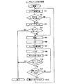
始めに、レーザスキャナ側の処理を示す。図15は第3の実施形態のステップS44におけるレーザスキャナ側の処理手順を示すフローチャートである。まず、エリアセンサ18による画像データの取込動作の開始に先立って、レーザスキャナ17によるレーザ走査を停止する(ステップS51)。エリアセンサ18による画像データの取込動作が終了するまで待機し(ステップS52)、その取込動作が終了すると、レーザ走査を開始する(ステップS53)。このレーザスキャナ17によるデジタルデータ(反射光データ)の取込(RAM22bへの転送)動作は、前述したようにDMAコントローラ19により行われるので、この間、CPU21はエリアセンサ側の処理(例えば、画像データの二値化処理)を実行することになる。そして、デジタルデータの取込動作の終了がDMAコントローラ19から伝達されると(ステップS54)、エリアセンサ側の画像データの二値化処理あるいはコード切り出し処理が終了するまで待機する(ステップS55)。この待機後、ステップS56からS60までの処理(図15の点線枠で囲まれる範囲の処理)を一気に行う。
First, processing on the laser scanner side will be described. FIG. 15 is a flowchart showing a processing procedure on the laser scanner side in step S44 of the third embodiment. First, prior to the start of the image data capturing operation by the
すなわち、RAM22bに記憶されたデジタルデータのデコード処理を行い(ステップS56)、デコード処理の結果がOKであるか否かを判別する(ステップS57)。デコードが正常に行われ、デコード処理の結果がOKである場合、本処理を終了する。一方、デコード処理の結果がNGである場合、エリアセンサ側の処理によってデコードフラグがセットされているか否かを判別する(ステップS58)。エリアセンサ側のデコード処理の結果がOKであるとして、デコードフラグがセットされている場合、本処理をそのまま終了する。
That is, the digital data stored in the
一方、デコードフラグがクリアされている場合、撮影フラグがセットされているか否かを判別する(ステップS59)。撮影フラグがセットされている場合、エリアセンサ側で再び画像データの取込動作が行われるとして、撮像フラグを値0にクリアした後(ステップS60)、ステップS51の処理に戻って、レーザ走査を停止する。一方、ステップS59で撮影フラグが値0にクリアされている場合、エリアセンサ側の画像データ取込動作はまだ行われないとして、ステップS54の処理に戻って、レーザ走査を継続してデータ取込動作を行う。 On the other hand, if the decode flag is cleared, it is determined whether or not the shooting flag is set (step S59). If the shooting flag is set, assuming that the image sensor capture operation is performed again on the area sensor side, the imaging flag is cleared to 0 (step S60), and then the process returns to step S51 to perform laser scanning. Stop. On the other hand, if the shooting flag is cleared to 0 in step S59, the image data capturing operation on the area sensor side is not yet performed, and the process returns to step S54 to continue laser scanning and capture data. Perform the action.
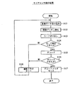
次に、エリアセンサ側の処理を示す。図16は第3の実施形態のステップS44におけるエリアセンサ側の処理手順を示すフローチャートである。まず、レーザスキャナ側のレーザ走査が停止した後、エリアセンサ18による画像データの取込動作を行う(ステップS71)。この画像データの取込動作では、前述したように、エリアセンサ18から出力されるデータは、CPU21によって読み取られ、RAM22bに記憶される。
Next, processing on the area sensor side will be described. FIG. 16 is a flowchart showing a processing procedure on the area sensor side in step S44 of the third embodiment. First, after the laser scanning on the laser scanner side is stopped, an image data capturing operation is performed by the area sensor 18 (step S71). In this image data capturing operation, as described above, the data output from the
RAM22bに1画面分の画像データが記憶されると、CPU21は、この画像データに対して二値化処理を行う(ステップS72)。二値化処理が終わると、レーザスキャナ側のデコード処理が終了するまで待機し(ステップS73)、レーザスキャナ側のデコード処理が終了すると、コード切り出し処理を行う(ステップS74)。コード切り出し処理が終了すると、再びレーザスキャナ側のデコード処理が終了するまで待機し(ステップS75)、レーザスキャナ側のデコード処理が終了すると、ステップS76からS80までのエリアセンサ側のデコード処理(図16の点線枠で囲まれる範囲の処理)に移行する。このエリアセンサ側のデコード処理では、レーザスキャナ側のデータ取込動作が終了すると、CPU21はレーザスキャナ側のデコード処理に切り替わり、このレーザスキャナ側のデコード処理が行われている間、エリアセンサ側のデコード処理は中断する。
When image data for one screen is stored in the
ステップS74の切り出し処理の結果、コードが検出されたか否かを判別する(ステップS76)。コードが検出されなかった場合、再度、画像データの取込動作を行うものとして撮影フラグを値1にセットし(ステップS79)、ステップS71の処理に戻る。一方、コードが検出された場合、本来のデコード処理を行う(ステップS77)。このデコード処理の結果、OKであるか否かを判別する(ステップS78)。デコード処理が正常に行われたとして、OKである場合、デコードフラグを値1にセットし(ステップS80)、本処理を終了する。一方、デコード処理の結果がNGである場合、ステップS79の処理に移行する。 It is determined whether or not a code has been detected as a result of the cutout process in step S74 (step S76). If the code is not detected, the photographing flag is set to 1 again to perform the image data capturing operation (step S79), and the process returns to step S71. On the other hand, if a code is detected, the original decoding process is performed (step S77). As a result of the decoding process, it is determined whether or not it is OK (step S78). If the decoding process is normally performed and the result is OK, the decoding flag is set to 1 (step S80), and this process ends. On the other hand, if the result of the decoding process is NG, the process proceeds to step S79.
このように、第3の実施形態のバーコード読取装置では、レーザスキャナおよびエリアセンサの両方を使ってバーコードを同時に読み取る際、その読取動作を高速化させることができる。即ち、レーザスキャナおよびエリアセンサのデコード処理のうち、早くOKが出た方のデコード処理結果を採用するので、読取対象であるバーコードの違いによる読取時間差を減らすことができ、全体としての読取動作を高速化させることができる。また、レーザスキャナおよびエリアセンサによる読取処理を効率良く同時に行うことで、これらの読取処理を高速化させることができる。 As described above, in the barcode reader of the third embodiment, when the barcode is read simultaneously using both the laser scanner and the area sensor, the reading operation can be speeded up. That is, among the decoding processes of the laser scanner and the area sensor, the decoding process result with the earlier OK is adopted, so the reading time difference due to the difference in the barcode to be read can be reduced, and the reading operation as a whole Can be speeded up. In addition, the reading process by the laser scanner and the area sensor can be efficiently performed at the same time, thereby speeding up the reading process.
また、エリアセンサによる画像の取り込み中、レーザ走査を停止することで、レーザスキャナによる反射光の影響を避けることができ、エリアセンサによって取り込まれる画像データの画質を向上できる。このため、デコード結果がNGとなる確率を低減でき、総合的に読み取り処理を短時間で実行することが可能となる。 Further, by stopping the laser scanning during the image capturing by the area sensor, the influence of the reflected light by the laser scanner can be avoided, and the image quality of the image data captured by the area sensor can be improved. For this reason, the probability that the decoding result is NG can be reduced, and the reading process can be comprehensively executed in a short time.
(第4の実施形態)
第4の実施形態におけるバーコード読取装置は、前記第3の実施形態と同様、レーザスキャナによるバーコード読取動作およびエリアセンサによるバーコード読取動作を同時に行うものである。バーコード読取装置の外観構成および電気的構成は、前記第3の実施形態と同様である。
(Fourth embodiment)
As in the third embodiment, the barcode reading apparatus in the fourth embodiment simultaneously performs a barcode reading operation by a laser scanner and a barcode reading operation by an area sensor. The appearance configuration and electrical configuration of the barcode reader are the same as those in the third embodiment.
第4の実施形態では、前記第3の実施形態と異なり、エリアセンサ18から出力される画像データは、レーザスキャナ17から出力されるデジタルデータ(反射光データ)と同様、DMAコントローラ19によりRAM22bにDMA転送されて記憶される。
In the fourth embodiment, unlike the third embodiment, the image data output from the
図17は第4の実施形態におけるレーザスキャナによるバーコード読取動作およびエリアセンサによるバーコード読取動作を同時に行う際のタイミングチャートである。本実施形態においても、CPU21はタイムシェアリング(時分割)でレーザスキャナ側およびエリアセンサ側のデータ処理を行う。読取開始キー214が押下され、同時バーコード読取動作が開始すると、最初はレーザスキャナ17によるレーザ走査を停止し、エリアセンサ18による画像データの取り込み動作が行われる。これは、前述したように、エリアセンサ18による画像データの取り込み動作を行っている際、レーザスキャナ17から読取対象であるバーコードの記録面にレーザ光が照射されると、エリアセンサ18がその反射光を受光してしまい、大きなノイズを含む画像データとなって画質が劣化することを防ぐためである。
FIG. 17 is a timing chart when the barcode reading operation by the laser scanner and the barcode reading operation by the area sensor are simultaneously performed in the fourth embodiment. Also in this embodiment, the
エリアセンサ18から出力される画像データは、DMAコントローラ19により、CPU21の介在なしにRAM22bに順次転送されて記憶される。エリアセンサ18による画像データの取り込み動作が終了すると、CPU21は、レーザスキャナ17にレーザ走査開始を指示するとともに、RAM22bに記憶された画像データの二値化処理を行う。 そして、レーザスキャナ17から出力されるデジタル信号は、DMAコントローラ19により、CPU21の介在なしにRAM22bに順次転送・記憶される。レーザスキャナ17による1回目の1走査分のデータ取込動作が終了すると、引き続いて2回目のデータ取込動作が行われる。このデータ取込動作は、次のエリアセンサ18による画像データ取込動作が始まるまで繰り返し行われる。
The image data output from the
そして、次のエリアセンサ18による画像データの取り込み動作が開始すると、レーザ走査を停止するとともに、この間を利用し、RAM22bに記憶された1回目〜n回目までのデジタルデータのデコード処理を行う。
Then, when the image data capturing operation by the
一方、エリアセンサ側では、画像データの取込動作が終了すると、すぐさま画像データの二値化処理を行い、二値化された画像データに対し、コード切り出し処理およびデコード処理を行う。デコード処理が終了すると、必要に応じて(つまり、デコード処理の結果がNGである場合)、次のエリアセンサ18による画像データの取込処理を行う。このような処理は、レーザスキャナ側あるいはエリアセンサ側のデコード処理の結果がOKとなるまで、あるいは使用者によって読取動作が中止されるまで繰り返されることになる。
On the other hand, on the area sensor side, as soon as the image data capturing operation is completed, the binarization processing of the image data is performed, and the code extraction processing and the decoding processing are performed on the binarized image data. When the decoding process ends, the
レーザスキャナ17およびエリアセンサ18による同時バーコード読取動作処理手順は、図14に示した前記第3の実施形態と同様である。すなわち、使用者によって読取開始キー214が押下されるのを待つ(ステップS41)。読取開始キー214が押下されると、デコードフラグを値0にクリアする(ステップS42)。さらに、撮像フラグを値0にクリアする(ステップS43)。そして、エリアセンサ18およびレーザスキャナ17による同時バーコード読取動作処理を行い(ステップS44)、表示部10に同時バーコード読取動作処理の結果を表示する(ステップS45)。この後、本処理を終了する。この同時バーコード読取動作処理では、CPU21がタイムシェアリング(時分割)でレーザスキャナ側の処理およびエリアセンサ側の処理を行うことになる。第4の実施形態では、前記第3の実施形態と比べ、ステップS44における同時バーコード読取動作処理だけが異なる。
The simultaneous barcode reading operation processing procedure by the
始めに、レーザスキャナ側の処理を示す。図18は第4の実施形態のステップS44におけるレーザスキャナ側の処理手順を示すフローチャートである。まず、エリアセンサ18による画像データの取込動作の開始に先立って、レーザスキャナ17によるレーザ走査を停止する(ステップS91)。そして、RAM22bにレーザスキャナ17によって取り込まれたデジタルデータが記憶されているか否かを判別する(ステップS92)。取り込まれたデジタルデータが記憶されていない場合、エリアセンサ18による画像データの取込動作が終了するまで待機し(ステップS95)、その取込動作が終了すると、カウンタnを値0にリセットし(ステップS96)、レーザスキャナ17によるレーザ走査を開始する(ステップS97)。カウンタnに値1を加算して(ステップS98)、カウンタnにおけるレーザスキャナ17によるデジタルデータの取込動作を行う(ステップS99)。このレーザスキャナ17によるデジタルデータの取込(RAM22bへの転送)動作は、前述したようにDMAコントローラ19により行われる。
First, processing on the laser scanner side will be described. FIG. 18 is a flowchart showing a processing procedure on the laser scanner side in step S44 of the fourth embodiment. First, prior to the start of the image data capturing operation by the
そして、エリアセンサ側の処理によってデコードフラグがセットされているか否かを判別する(ステップS100)。エリアセンサ側のデコード処理の結果がOKであるとして、デコードフラグがセットされている場合、本処理をそのまま終了する。一方、デコードフラグがクリアされている場合、撮影フラグがセットされているか否かを判別する(ステップS101)。撮影フラグがセットされている場合、エリアセンサ側で再び画像データ取込動作が行われるとして、撮像フラグを値0にクリアした後(ステップS102)、ステップS91の処理に戻って、レーザ走査を停止する。一方、ステップS101で撮影フラグが値0にクリアされている場合、エリアセンサ側の画像データの取込動作はまだ行われないとして、ステップS98の処理に戻って、カウンタnに値1を加算し、レーザ走査を継続してデータ取込動作を行う。 And it is discriminate | determined whether the decoding flag is set by the process by the area sensor side (step S100). If the decoding result on the area sensor side is OK and the decoding flag is set, this processing is terminated as it is. On the other hand, if the decode flag is cleared, it is determined whether or not the shooting flag is set (step S101). If the image capturing flag is set, the image data capturing operation is performed again on the area sensor side, and after clearing the image capturing flag to 0 (step S102), the process returns to step S91 to stop laser scanning. To do. On the other hand, if the shooting flag is cleared to 0 in step S101, the image data capturing operation on the area sensor side is not yet performed, and the process returns to step S98 to add 1 to the counter n. Then, the laser scanning is continued and the data fetching operation is performed.
一方、ステップS92で取り込まれたデジタルデータがRAM22bに記憶されている場合、RAM22bに記憶されたデジタルデータのデコード処理を行い(ステップS93)、デコード処理の結果がOKであるか否かを判別する(ステップS94)。デコード処理が正常に行われ、デコード処理の結果がOKである場合、本処理を終了する。一方、デコード処理の結果がNGである場合、ステップS95の処理に移行する。
On the other hand, when the digital data captured in step S92 is stored in the
次に、エリアセンサ側の処理を示す。図19は第4の実施形態のステップS44におけるエリアセンサ側の処理手順を示すフローチャートである。まず、レーザスキャナ側のレーザ走査が停止した後、エリアセンサ18による画像データの取込動作を行う(ステップS121)。この画像データの取込動作では、前述したように、エリアセンサ18から出力されるデータは、DMAコントローラ19によりCPU21の介在なしにRAM22bに順次転送されて記憶される。
Next, processing on the area sensor side will be described. FIG. 19 is a flowchart showing a processing procedure on the area sensor side in step S44 of the fourth embodiment. First, after the laser scanning on the laser scanner side is stopped, an image data capturing operation by the
RAM22bに1画面分の画像データが記憶されると、CPU21は、この画像データに対して二値化処理を行う(ステップS122)。二値化処理が終わると、そのままコード切り出し処理を行う(ステップS123)。そして、コード切り出し処理の結果、コードが検出されたか否かを判別する(ステップS124)。コードが検出されなかった場合、再度、画像データの取込動作を行うものとして撮影フラグを値1にセットし(ステップS128)、ステップS121の処理に戻る。一方、コードが検出された場合、デコード処理を行う(ステップS125)。このデコード処理の結果、OKであるか否かを判別する(ステップS126)。デコード処理が正常に行われたとして、OKである場合、デコードフラグを値1にセットし(ステップS127)、本処理を終了する。一方、デコード処理の結果がNGである場合、ステップS128の処理に移行する。
When the image data for one screen is stored in the
このように、第4の実施形態のバーコード読取装置では、前記第3の実施形態と同様、レーザスキャナおよびエリアセンサの両方を使ってバーコードを同時に読み取る際、その読取動作を高速化させることができる。また、エリアセンサ側では、画像データがRAMに記憶されると、CPUは待機することなく、データ処理を行うので、より一層の高速化を図ることができる。 As described above, in the barcode reader of the fourth embodiment, as in the third embodiment, when reading the barcode simultaneously using both the laser scanner and the area sensor, the reading operation is speeded up. Can do. On the area sensor side, when the image data is stored in the RAM, the CPU performs the data processing without waiting, so that the speed can be further increased.
なお、本発明は、上記実施形態の構成及び動作に限られるものではなく、適宜変形して適用することが可能である。例えば、上記各実施形態では、レーザスキャナあるいはエリアセンサから出力されるデータは、DMA転送あるいはCPUによる読み書き動作によって一旦RAMに記憶された後、CPUによってデコード等のデータ処理が行われたが、レーザスキャナおよびエリアセンサそれぞれにバッファメモリを設け、RAMへのデータ転送を行うことなく、データ処理を行えるようにしてもよい。 Note that the present invention is not limited to the configuration and operation of the above-described embodiment, and can be appropriately modified and applied. For example, in each of the above embodiments, the data output from the laser scanner or area sensor is temporarily stored in the RAM by DMA transfer or read / write operation by the CPU, and then data processing such as decoding is performed by the CPU. A buffer memory may be provided in each of the scanner and the area sensor so that data processing can be performed without performing data transfer to the RAM.
図20は本実施形態の変形例におけるバーコード読取装置の電気的構成を示すブロック図である。この変形例は、レーザスキャナおよびエリアセンサそれぞれにバッファメモリを設けたものである。レーザスキャナ17およびエリアセンサ18それぞれに設けられたバッファメモリ311、312はバス24に接続されており、CPU21はバス24を介してバッファメモリ311、312に一時的に記憶されたデータに対してデータ処理を施すことができる。バッファメモリのサイズとしては、レーザスキャナ側では、1走査ライン分が望ましいが、それより大きくても小さくてもよい。また、エリアセンサ側では、1画面分であることが望ましいが、それより大きくても小さくてもよい。このように、バッファメモリを設けることで、一層の高速化を図ることができる。
FIG. 20 is a block diagram showing an electrical configuration of a barcode reader according to a modification of the present embodiment. In this modification, a buffer memory is provided in each of the laser scanner and the area sensor. The
また、上記第3、第4の実施形態では、1つのCPUによってレーザスキャナ側のデータ処理およびエリアセンサ側のデータ処理の両方を、タイムシェアリングで行っていたが、2つ以上のCPUおよびこれらの調停回路を設け、レーザスキャナ側のデータ処理とエリアセンサ側のデータ処理を並列的に行うようにしてもよく、一層の高速化を図ることが可能である。 In the third and fourth embodiments, both data processing on the laser scanner side and data processing on the area sensor side are performed by time sharing by one CPU. However, two or more CPUs and these The arbitration circuit may be provided so that the data processing on the laser scanner side and the data processing on the area sensor side may be performed in parallel, and the speed can be further increased.
本発明は、1次元バーコードと2次元バーコードの読取動作を簡単に切り替えることが可能となる効果を有する。また、複数の読取手段による同時読取動作を高速化させることが可能となる効果を有する。したがって、本発明は、1次元バーコード及び2次元バーコードを読み取り可能なバーコード読取装置及びバーコード読取方法等に有用である。 The present invention has an effect that the reading operation of a one-dimensional barcode and a two-dimensional barcode can be easily switched. In addition, there is an effect that the simultaneous reading operation by a plurality of reading means can be speeded up. Therefore, the present invention is useful for a barcode reading apparatus and a barcode reading method capable of reading a one-dimensional barcode and a two-dimensional barcode.
1 バーコード読取装置
10 表示部
12 操作部
13 第2の読取開始キー
14 第1の読取開始キー
17 レーザスキャナ
18 エリアセンサ
19 DMAコントローラ
21 CPU
22 メモリ
22a ROM
22b RAM
114、214 読取開始キー
DESCRIPTION OF
22
22b RAM
114, 214 Scan start key
Claims (11)
前記バーコード記録面の画像を取り込み、取り込まれた画像を解析してバーコードを読み取る第2の読取手段と、
前記第1の読取手段による読取動作を開始させる第1の開始指示手段と、
前記第2の読取手段による読取動作を開始させる第2の開始指示手段とを備えたバーコード読取装置。 First reading means for scanning the bar code recording surface with light and reading the bar code from the reflected light;
Second reading means for capturing an image of the barcode recording surface, analyzing the captured image, and reading the barcode;
First start instruction means for starting a reading operation by the first reading means;
A barcode reading apparatus comprising: a second start instruction unit that starts a reading operation by the second reading unit.
前記第1の開始指示手段の機能を有する押下自在な第1の操作キーと、前記第2の開始指示手段の機能を有する押下自在な第2の操作キーとを備え、
前記第1の操作キーが押下された場合、前記第1の読取手段による読取動作を開始させ、前記第2の操作キーが押下された場合、前記第2の読取手段による読取動作を開始させるバーコード読取装置。 The barcode reader according to claim 1,
A pressable first operation key having a function of the first start instruction means; and a pressable second operation key having a function of the second start instruction means;
A bar that starts the reading operation by the first reading unit when the first operation key is pressed, and starts the reading operation by the second reading unit when the second operation key is pressed. Code reader.
前記第1の開始指示手段および前記第2の開始指示手段の機能を有する、第1の押下状態および第2の押下状態の2段階に押下自在な操作キーを備え、
前記操作キーの前記第1の押下状態が検出された場合、前記第1の読取手段による読取動作を開始させ、前記操作キーの前記第2の押下状態が検出された場合、前記第2の読取手段による読取動作を開始させるバーコード読取装置。 The barcode reader according to claim 1,
An operation key having functions of the first start instruction means and the second start instruction means, which can be pressed in two stages of a first pressed state and a second pressed state;
When the first pressing state of the operation key is detected, a reading operation by the first reading unit is started, and when the second pressing state of the operation key is detected, the second reading is performed. A bar code reader for starting a reading operation by means.
前記バーコード記録面の画像を取り込み、取り込まれた画像のデータを解析してバーコードを読み取る第2の読取手段と、
前記第1および第2の読取手段による同時読取動作を開始させる開始指示手段と、
前記同時読取動作が開始された場合、前記第1および第2の読取手段による同時読取動作を制御する読取制御手段とを備え、
前記読取制御手段は、前記第2の読取手段による画像の取り込み中、前記第1の読取手段による光の走査を停止させる走査停止手段を備え、前記第1の読取手段による読取動作と前記第2の読取手段による読取動作とを重複させずに行うように制御するバーコード読取装置。 A first reading unit that captures the reflected light data while scanning the barcode recording surface, analyzes the captured reflected light data, and reads the barcode;
Second reading means for capturing an image of the barcode recording surface, analyzing data of the captured image, and reading the barcode;
Start instruction means for starting a simultaneous reading operation by the first and second reading means;
A reading control means for controlling the simultaneous reading operation by the first and second reading means when the simultaneous reading operation is started;
The reading control means includes a scanning stop means for stopping the scanning of light by the first reading means during the image capturing by the second reading means, and the reading operation by the first reading means and the second reading means. A barcode reader which controls the reading operation by the reading means so as not to overlap.
前記読取制御手段は、前記第2の読取手段による今回の画像の取り込みから次回の画像の取り込みまでの間に、前記第1の読取手段による反射光のデータの取り込みおよびこの反射光のデータの解析を連続して行うバーコード読取装置。 The barcode reader according to claim 4, wherein
The reading control means captures the reflected light data by the first reading means and analyzes the reflected light data between the current image capturing by the second reading means and the next image capturing. Bar code reader that performs the above continuously.
前記読取制御手段は、前記第2の読取手段による今回の画像の取り込み後、前記第1の読取手段による反射光のデータの取り込みを繰り返し、前記第2の読取手段による次回の画像の取り込み中、前記第1の読取手段により繰り返し取り込まれた反射光のデータをまとめて解析するバーコード読取装置。 The barcode reader according to claim 4, wherein
The reading control unit repeatedly captures reflected light data by the first reading unit after capturing the current image by the second reading unit, and during the next image capturing by the second reading unit, A bar code reading apparatus that collectively analyzes data of reflected light repeatedly taken by the first reading means.
前記読取制御手段は、前記第1および第2の読取手段による同時読取動作を時分割に制御するバーコード読取装置。 The barcode reader according to any one of claims 4 to 6,
The barcode reading device, wherein the reading control means controls the simultaneous reading operation by the first and second reading means in a time-sharing manner.
前記第1の読取手段によって取り込まれる反射光のデータは、DMA転送により、プロセッサに接続されるバスを介してメモリに記憶されるバーコード読取装置。 The barcode reader according to any one of claims 4 to 7,
Reflected light data captured by the first reading means is stored in a memory via a bus connected to a processor by DMA transfer.
前記第1の読取手段によって取り込まれる反射光のデータおよび前記第2の読取手段によって取り込まれる画像のデータは、DMA転送により、プロセッサに接続されるバスを介してメモリに記憶されるバーコード読取装置。 The barcode reader according to claim 6, wherein
A barcode reader in which reflected light data captured by the first reading unit and image data captured by the second reading unit are stored in a memory via a bus connected to a processor by DMA transfer .
前記第1の読取手段によって取り込まれる反射光のデータおよび前記第2の読取手段によって取り込まれる画像のデータは、それぞれ前記第1の読取手段および前記第2の読取手段に設けられたバッファメモリに記憶されるバーコード読取装置。 The barcode reader according to any one of claims 4 to 7,
Reflected light data captured by the first reading unit and image data captured by the second reading unit are stored in buffer memories provided in the first reading unit and the second reading unit, respectively. Barcode reader.
前記バーコード記録面の画像を取り込み、取り込まれた画像のデータを解析してバーコードを読み取る第2の読取ステップと、
操作入力に応じて前記第1および第2の読取手段による同時読取動作を開始させる読取開始ステップと、
前記同時読取動作が開始された場合、前記第1および第2の読取ステップによる同時読取動作を制御する読取制御ステップとを有し、
前記読取制御ステップにおいて、前記第2の読取ステップによる画像の取り込み中、前記第1の読取ステップによる光の走査を停止させる走査停止ステップを有し、前記第1の読取ステップによる読取動作と前記第2の読取ステップによる読取動作とを重複させずに行うように制御するバーコード読取方法。 A first reading step of capturing the reflected light data while scanning the barcode recording surface, analyzing the captured reflected light data, and reading the barcode;
A second reading step of capturing an image of the barcode recording surface, analyzing the captured image data, and reading the barcode;
A reading start step for starting a simultaneous reading operation by the first and second reading means in response to an operation input;
A reading control step for controlling a simultaneous reading operation by the first and second reading steps when the simultaneous reading operation is started;
The reading control step includes a scanning stop step of stopping scanning of light by the first reading step during capturing of the image by the second reading step, and the reading operation by the first reading step and the first reading step A barcode reading method for performing control so as to perform the reading operation in step 2 without overlapping.
Priority Applications (1)
| Application Number | Priority Date | Filing Date | Title |
|---|---|---|---|
| JP2004104238A JP2005292990A (en) | 2004-03-31 | 2004-03-31 | Bar code reading apparatus and bar code reading method |
Applications Claiming Priority (1)
| Application Number | Priority Date | Filing Date | Title |
|---|---|---|---|
| JP2004104238A JP2005292990A (en) | 2004-03-31 | 2004-03-31 | Bar code reading apparatus and bar code reading method |
Publications (1)
| Publication Number | Publication Date |
|---|---|
| JP2005292990A true JP2005292990A (en) | 2005-10-20 |
Family
ID=35325885
Family Applications (1)
| Application Number | Title | Priority Date | Filing Date |
|---|---|---|---|
| JP2004104238A Pending JP2005292990A (en) | 2004-03-31 | 2004-03-31 | Bar code reading apparatus and bar code reading method |
Country Status (1)
| Country | Link |
|---|---|
| JP (1) | JP2005292990A (en) |
Cited By (3)
| Publication number | Priority date | Publication date | Assignee | Title |
|---|---|---|---|---|
| JP2008186364A (en) * | 2007-01-31 | 2008-08-14 | Denso Wave Inc | Information reader |
| JP2009009196A (en) * | 2007-06-26 | 2009-01-15 | Casio Comput Co Ltd | Operating device |
| JP2014096178A (en) * | 2014-01-24 | 2014-05-22 | Casio Comput Co Ltd | Terminal device and program |
-
2004
- 2004-03-31 JP JP2004104238A patent/JP2005292990A/en active Pending
Cited By (3)
| Publication number | Priority date | Publication date | Assignee | Title |
|---|---|---|---|---|
| JP2008186364A (en) * | 2007-01-31 | 2008-08-14 | Denso Wave Inc | Information reader |
| JP2009009196A (en) * | 2007-06-26 | 2009-01-15 | Casio Comput Co Ltd | Operating device |
| JP2014096178A (en) * | 2014-01-24 | 2014-05-22 | Casio Comput Co Ltd | Terminal device and program |
Similar Documents
| Publication | Publication Date | Title |
|---|---|---|
| JP5043736B2 (en) | Imaging apparatus and control method thereof | |
| US8704930B2 (en) | Image display apparatus, imaging apparatus, image display method, and program | |
| JP4551945B2 (en) | Portable electronic devices | |
| JP2008508609A (en) | System and method for decoding optical code read by an imaging device based optical code reader | |
| JP5771461B2 (en) | TRACKING DEVICE, TRACKING METHOD, AND TRACKING PROGRAM | |
| WO2002013514A1 (en) | Electronic camera | |
| JP2015015592A (en) | Tracking apparatus, tracking method, and tracking program | |
| JP7747699B2 (en) | How to create a video | |
| JP5693022B2 (en) | Display control device, display control system, and control method, program, and storage medium thereof | |
| JP2005292990A (en) | Bar code reading apparatus and bar code reading method | |
| JP6172973B2 (en) | Image processing device | |
| JP2020030646A (en) | Portable terminal device, information recording method, and program | |
| JP5043787B2 (en) | Imaging apparatus and control method thereof | |
| JP5310039B2 (en) | Imaging processing apparatus and program | |
| JPWO2021065175A5 (en) | ||
| JP2015212866A (en) | Optical information reader and optical information read method | |
| CN110650298A (en) | Image processing apparatus, image processing method, and storage medium | |
| JP4963441B2 (en) | Image reading apparatus and image forming apparatus | |
| JP7073117B2 (en) | Image pickup device, control method of image pickup device, and program | |
| JP5965654B2 (en) | TRACKING DEVICE, IMAGING DEVICE, TRACKING METHOD USED FOR IMAGING DEVICE | |
| JPH08271980A (en) | Image reader | |
| JP4665607B2 (en) | Camera, camera control program, and camera control method | |
| JP2013165363A (en) | Imaging apparatus | |
| JP2001283149A (en) | Information code reading device | |
| JP7558280B2 (en) | Imaging device, imaging method, and imaging program |
Legal Events
| Date | Code | Title | Description |
|---|---|---|---|
| RD04 | Notification of resignation of power of attorney |
Free format text: JAPANESE INTERMEDIATE CODE: A7424 Effective date: 20060327 |
|
| A621 | Written request for application examination |
Free format text: JAPANESE INTERMEDIATE CODE: A621 Effective date: 20060912 |
|
| RD02 | Notification of acceptance of power of attorney |
Free format text: JAPANESE INTERMEDIATE CODE: A7422 Effective date: 20071114 |
|
| RD04 | Notification of resignation of power of attorney |
Free format text: JAPANESE INTERMEDIATE CODE: A7424 Effective date: 20071121 |
|
| RD02 | Notification of acceptance of power of attorney |
Free format text: JAPANESE INTERMEDIATE CODE: A7422 Effective date: 20071128 |
|
| RD04 | Notification of resignation of power of attorney |
Free format text: JAPANESE INTERMEDIATE CODE: A7424 Effective date: 20071205 |
|
| RD04 | Notification of resignation of power of attorney |
Free format text: JAPANESE INTERMEDIATE CODE: A7424 Effective date: 20071212 |
|
| A977 | Report on retrieval |
Free format text: JAPANESE INTERMEDIATE CODE: A971007 Effective date: 20080312 |
|
| A131 | Notification of reasons for refusal |
Free format text: JAPANESE INTERMEDIATE CODE: A131 Effective date: 20080319 |
|
| A02 | Decision of refusal |
Free format text: JAPANESE INTERMEDIATE CODE: A02 Effective date: 20080806 |