JP4551945B2 - Portable electronic devices - Google Patents
Portable electronic devices Download PDFInfo
- Publication number
- JP4551945B2 JP4551945B2 JP2008093926A JP2008093926A JP4551945B2 JP 4551945 B2 JP4551945 B2 JP 4551945B2 JP 2008093926 A JP2008093926 A JP 2008093926A JP 2008093926 A JP2008093926 A JP 2008093926A JP 4551945 B2 JP4551945 B2 JP 4551945B2
- Authority
- JP
- Japan
- Prior art keywords
- portable electronic
- electronic device
- touch
- input unit
- display
- Prior art date
- Legal status (The legal status is an assumption and is not a legal conclusion. Google has not performed a legal analysis and makes no representation as to the accuracy of the status listed.)
- Expired - Lifetime
Links
Images


Description
本発明は、表示装置を有する携帯型電子機器に関し、特に、操作入力部の構成を改良した携帯型電子機器に関する。 The present invention relates to a portable electronic device having a display device, and particularly to a portable electronic device having an improved operation input unit.
デジタルカメラ等の携帯型電子機器は、多機能化に伴い、多くの操作部材を必要とするようになっている。一方、機器自体の小型化、薄型化、及び表示部の大画面化の要求も大きく、多くの操作部材を配置することが困難になりつつある。そのため、表示部の表示画面上に配置されたタッチパネルを利用することにより、操作部を減少させたものが提案されているが、表示画面に直接指が触れるため、画面が汚れてしまうという欠点があった。 Portable electronic devices such as digital cameras are required to have a large number of operation members as they become multifunctional. On the other hand, there is a great demand for downsizing and thinning of the device itself and an increase in the screen size of the display unit, and it is becoming difficult to arrange many operation members. For this reason, a touch panel arranged on the display screen of the display unit has been proposed to reduce the operation unit. However, since the finger touches the display screen directly, the screen is soiled. there were.
また、線状かつ連続的に配置したタッチ検出センサを含むタッチ入力部を、表示部の周辺に配置したものも提案されている(特開平11−194872号公報、特開平11−195353号公報参照)が、タッチ入力部による操作は、表示項目の選択に留まり、操作性は必ずしもよくなかった。 In addition, a touch input unit including touch detection sensors arranged linearly and continuously is arranged around the display unit (see Japanese Patent Laid-Open Nos. 11-19472 and 11-195353). However, the operation by the touch input unit is limited to the selection of display items, and the operability is not always good.
本発明は、上記事情に鑑み、機器自体の小型化、薄型化を実現し、かつ操作性を向上させた携帯型電子機器を提供することを目的とする。 In view of the above circumstances, an object of the present invention is to provide a portable electronic device in which the device itself is reduced in size and thickness and the operability is improved.
本発明の携帯型電子機器は、表示装置を有する携帯型電子機器であって、線状かつ連続的に配置したタッチ検出センサを含むタッチ入力部を、前記表示装置の周辺に設け、前記タッチ入力部が検出したタッチ位置及びタッチ状態での移動に応じて前記携帯型電子機器の制御操作又は前記表示装置に表示された項目に基づく入力操作が行われるものであり、前記表示装置は、略矩形形状であり、前記タッチ検出センサは、略L字状であって、前記表示装置の略直交する2辺に略平行に設けられ、前記タッチ入力部は、前記L字の角部へのタッチ後に有効状態となるものである。 The portable electronic device of the present invention is a portable electronic device having a display device, wherein a touch input unit including a touch detection sensor arranged linearly and continuously is provided around the display device, and the touch input An input operation based on a control operation of the portable electronic device or an item displayed on the display device is performed according to the touch position detected by the unit and the movement in the touch state, and the display device is substantially rectangular The touch detection sensor is substantially L-shaped, and is provided substantially parallel to two substantially orthogonal sides of the display device, and the touch input unit is configured to touch the corner of the L-shape. It becomes a valid state.
本発明の携帯型電子機器における前記入力操作は、前記タッチ位置に対応する項目の被選択候補が表示された後の、タッチ状態での移動位置によって行われるものである。 The input operation in the portable electronic device of the present invention is performed according to the moving position in the touch state after the selection candidate of the item corresponding to the touch position is displayed.
本発明の携帯型電子機器における前記タッチ入力部のタッチ状態での移動に応じた前記携帯型電子機器の制御操作は、前記表示装置に表示される画像の表示倍率の変更操作を含むものである。 The control operation of the portable electronic device according to the movement of the touch input unit in the touch state in the portable electronic device of the present invention includes a change operation of a display magnification of an image displayed on the display device.
本発明の携帯型電子機器における前記タッチ入力部のタッチ状態での移動に応じた前記携帯型電子機器の制御操作は、前記表示装置に表示される画像の表示領域の変更操作を含むものである。 The control operation of the portable electronic device according to the movement of the touch input unit in the touch state in the portable electronic device of the present invention includes a change operation of a display area of an image displayed on the display device.
本発明の携帯型電子機器における前記タッチ入力部のタッチ状態での移動に応じた前記携帯型電子機器の制御操作は、前記表示装置に表示される画像の連続的なコマ送り操作を含むものである。 The control operation of the portable electronic device according to the movement of the touch input unit in the touch state in the portable electronic device of the present invention includes a continuous frame advance operation of an image displayed on the display device.
本発明の携帯型電子機器は、デジタルカメラであり、前記タッチ入力部のタッチ状態での移動に応じた前記携帯型電子機器の制御操作は、撮影倍率の変更操作を含むものである。 The portable electronic device of the present invention is a digital camera, and the control operation of the portable electronic device according to the movement of the touch input unit in the touched state includes an operation for changing the photographing magnification.
本発明の携帯型電子機器における前記タッチ検出センサは、タッチパッドで構成されるものである。 The touch detection sensor in the portable electronic device of the present invention includes a touch pad.
本発明の携帯型電子機器における前記タッチ検出センサは、接点式スイッチで構成されるものである。 The touch detection sensor in the portable electronic device of the present invention includes a contact type switch.
本発明の携帯型電子機器における前記接点式スイッチは、メンブレンスイッチで構成されるものである。 In the portable electronic device of the present invention, the contact switch is a membrane switch.
以上の説明から明らかなように、本発明によれば、機器自体の小型化、薄型化を実現し、かつ操作性を向上させた携帯型電子機器を提供することができる。 As is apparent from the above description, according to the present invention, it is possible to provide a portable electronic device that realizes a reduction in size and thickness of the device itself and an improvement in operability.
以下、本発明の実施の形態について、携帯型電子機器としてデジタルカメラを例に図面を用いて説明する。 Hereinafter, embodiments of the present invention will be described with reference to the drawings using a digital camera as an example of a portable electronic device.
(第1の実施の形態)
第1の実施の形態を図1から図7を用いて説明する。図1は、第1の実施の形態のデジタルカメラの斜視図であり、(a)はその正面を、(b)はその背面を示したものである。図1のデジタルカメラは、電源スイッチ1、レンズ2、光学ファインダー3、シャッターボタン4、補助光発光部5、記録メディア挿入部6、画像モニタ7、タッチパッド8、9を含んで構成される。
(First embodiment)
A first embodiment will be described with reference to FIGS. 1A and 1B are perspective views of the digital camera according to the first embodiment, in which FIG. 1A shows its front and FIG. 1B shows its back. The digital camera shown in FIG. 1 includes a power switch 1, a
図1のデジタルカメラにおいて、電源スイッチ1は、デジタルカメラの撮影モード/再生モードの切替えスイッチを兼用している。また、補助光発光部5は、低照度時に補助光を発光するもので、ストロボ、LED等が利用される。
In the digital camera shown in FIG. 1, the power switch 1 also serves as a switch for switching between the photographing mode / reproduction mode of the digital camera. The auxiliary
タッチパッド8、9は、操作者の指等の接触を検出するタッチ検出センサであり、タッチパッド8は、画像モニタ7のH方向(水平方向)に略平行に設けられ、H方向の接触位置信号を出力するものであり、タッチパッド9は、画像モニタ7のV方向(垂直方向)に略平行に設けられ、V方向の接触位置信号を出力するものである。すなわち、タッチパッド8、9は、一次元(線状)の接触位置をほぼ連続に検出するものである。したがって、タッチパッド8、9の幅は、指の接触を確実に検出できる大きさで充分である。
The
タッチパッド8、9は、画像モニタ7に表示された項目及び被選択候補の選択及び入力を行うタッチ入力部の一部を形成する。また、タッチパッド8、9は、画像モニタ7に表示された画像の表示内容の操作を行うタッチ入力部の一部を形成する。さらに、画像撮影時の撮影倍率の制御を行うタッチ入力部の一部を形成する。これらの入力操作に際しては、タッチパッド8、9の接触位置信号だけでなく、接触した状態での移動操作も利用される。
The
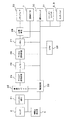
図2は、図1のデジタルカメラの概略ブロック構成図である。デジタルカメラは、レンズ2、シャッター・絞り21、撮像デバイス22、補助光発光部5、及び駆動回路23を含む撮像部、アナログ信号処理部24、A/D変換部25、デジタル信号処理部26、出力用メモリ27、及び圧縮伸張処理部28を含む信号処理部、メディアインタフェース32及び画像モニタ8を含む出力部、操作スイッチ30、シャッタースイッチ31、及びタッチパッド8、9を含む操作部、並びにデジタルカメラ全体を制御するCPU29を含んで構成される。
FIG. 2 is a schematic block diagram of the digital camera shown in FIG. The digital camera includes an imaging unit including a
撮像部、及び信号処理部の構成は、従来のデジタルカメラと同じであるので簡単に説明する。レンズ2とシャッター・絞り21を通った光は、CCD等の撮像デバイス22の上に焦点を結び、撮影画像信号が取得される。ここでシャッターは撮像デバイス22から信号を読み出すときのスミア発生を防ぐものである。撮像デバイス22は、シャッタースイッチ31のオン操作を契機として、所定のタイミングで駆動回路23によって駆動され、画像信号を出力する。駆動回路23は、撮像デバイス22の駆動電圧条件によっては省略も可能である。
Since the configuration of the imaging unit and the signal processing unit is the same as that of a conventional digital camera, it will be briefly described. The light passing through the
画像信号は、アナログ信号処理された後、A/D変換され、デジタル信号処理を経て出力用メモリ27に一時的に記録される。ここで、画像モニタ8に表示する場合は、出力用メモリ27の内容を読み出して画像モニタ8に送る。出力用メモリ27の撮影画像は、圧縮伸張処理部28で圧縮処理され、メディアインタフェース32を経て、図示しないメモリカード等の記録メディアに記録される。撮影モードによっては圧縮処理を省略することもできる。
The image signal is analog signal processed, A / D converted, and temporarily recorded in the
記録メディアに記録された画像を画像モニタ8に表示させる場合は、記録メディアから読取った画像情報を圧縮伸張処理部28で伸張処理して出力用メモリ27に書込み、画像モニタ8に送る。
When the image recorded on the recording medium is displayed on the
これらの動作は、電源スイッチ1を含む操作スイッチ30、シャッターボタン4によって操作されるシャッタースイッチ31、及びタッチパッド8、9の位置検出信号に応じて、CPU23の制御のもとに行われる。CPU23は、タッチパッド8、9の位置検出信号の変化によって、指を接触させた状態での移動を判断する。
These operations are performed under the control of the
次に、タッチパッド8、9を利用した設定操作について、図3のフローを用いて説明する。撮影時には、撮影動作モードの設定が可能であり、電源スイッチ1を操作して撮影モードに設定すると、図4に示されるような、明るさ設定メニューマーク34を含む複数の項目メニューマーク33〜36が表示される。この状態でメニューマーク34の下部のタッチパッド8に指を接触させる(ステップ301)と、図5に示すような画面となり、項目メニューマーク34に対応する項目の被選択候補37が表示される(ステップ302)。この状態で、タッチパッド上の指を接触させた(ステップ303)まま、ゆびを+H方向又は−H方向に移動させると、被選択候補の内の1つが選択される(ステップ304)。そして、この状態で、指をタッチパッド8から離す(ステップ305)と、選択されていた被選択候補が設定される(ステップ306)。
Next, a setting operation using the
タッチパッド8と9の両方を用いる場合、タッチパッド8によって、所定の項目を選択して被選択候補を表示させ、タッチパッド9に接触させて被選択候補の内の1つを選択することも可能である。
When both the
続いて、タッチパッド8、9によるデジタルカメラの制御操作について説明する。制御操作の1つの例は、撮影時の撮影倍率の変更操作である。撮影倍率の変更操作は、タッチパッド9に指を接触させた状態で移動させることにより行われる。すなわち、撮影時、指をタッチパッド9に接触させた状態で、+V方向に移動させるとズームイン操作となり、−V方向に移動させるとズームアウト操作となる。
Subsequently, a control operation of the digital camera using the
制御操作の他の例は、画像モニタ7に表示される再生画像の変更操作である。図6に、複数の撮影画像を連続的にコマ送りするときの画像モニタ7の表示例を示す。図6(a)は、水平方向へコマ送りする例であり、図6(b)は、垂直方向へコマ送りする例である。水平方向のコマ送りは、指をタッチパッド8に接触させた状態で+H方向又は−H方向に移動させて、フレーム境界60を+H方向又は−H方向に移動させることにより行う。また、垂直方向のコマ送りは、指をタッチパッド9に接触させた状態で+V方向又は−V方向に移動させて、フレーム境界60を+V方向又は−V方向に移動させることにより行う。
Another example of the control operation is an operation for changing a reproduced image displayed on the
再生画像の表示倍率の変更を行う場合は、タッチパッド9によって拡大/縮小制御を行い、タッチパッド8によって拡大画像の表示領域の変更を行う。再生画像の拡大/縮小制御時は、撮影時と同様、指をタッチパッド9に接触させた状態で、+V方向に移動させるとズームイン操作となり、−V方向に移動させるとズームアウト操作となる。再生画像を拡大表示させたとき、指をタッチパッド8に接触させた状態で移動させると、拡大画像の表示領域を変更することができる。
When changing the display magnification of the reproduced image, enlargement / reduction control is performed using the
このように、タッチパッド8、9の接触位置だけでなく、接触状態での移動情報を利用することにより、多くの操作機能を実現することができる。なお、接触移動に割当てる機能は、デジタルカメラの動作モードによって適宜設定可能である。
Thus, many operation functions can be realized by using not only the contact positions of the
図1に示したデジタルカメラは、画像モニタ7の直交する2辺に略平行に2つのタッチパッド8、9を設けたが、タッチパッド8又は9のいずれか一方のみを設けてもよい。また、タッチパッドは直線形状に限らず、任意の形状とすることができる。
The digital camera shown in FIG. 1 is provided with two
図7は、1つのタッチパッド10を略L字状に形成し、画像モニタ7の直交する2辺に略平行に設けたものである。タッチパッド10の領域11には、図1のタッチパッド8と同様の機能を与え、領域12には、図1のタッチパッド9と同様の機能を与える。したがって、これまで説明したような制御操作及び入力操作が可能である。
In FIG. 7, one
タッチパッド10の領域13は、画像モニタ7と直接対応する位置関係にないので、特別な機能を与える。特別な機能の一例は、タッチパッドによる入力の有効状態を制御する機能である。すなわち、タッチパッド10による操作に際して、領域13にタッチした後に、タッチ入力を有効とするものである。このような構成とすると、不用意にタッチパッドに触れて、予期しない操作が行われるのを防ぐことができる
Since the
特別な機能の他の例は、領域13のタッチ入力を、予め定めた情報の直接入力と判断するものである。このように構成すると、頻繁に利用される撮影条件等をワンタッチで設定することができる。
Another example of the special function is to determine that the touch input in the
(第2の実施の形態)
図8は、第2の実施の形態のデジタルカメラを示したものであり、(a)はその背面斜視図であり、(b)は画像モニタ周辺部の概略断面図である。図8のデジタルカメラは、操作者の指等の接触を検出するタッチ検出センサとして接点式スイッチ群80を備えている。接点式スイッチ群80は、凸状押圧部81と複数のスイッチ部材82を含んで構成される。接点式スイッチ群を構成するスイッチとしてはメンブレンスイッチ等が考えられる。但し、スイッチ部材82は、領域Aと領域B、又はいずれか一方にのみ設けられ、他の部分は凸状押圧部のみを有するダミーである。
(Second Embodiment)
8A and 8B show a digital camera according to the second embodiment, in which FIG. 8A is a rear perspective view thereof, and FIG. 8B is a schematic cross-sectional view of a peripheral portion of an image monitor. The digital camera shown in FIG. 8 includes a
接点式スイッチ群80の領域Aには、図1のタッチパッド8と同様の機能を与え、領域Bには、図1のタッチパッド9と同様の機能を与える。したがって、第1の実施の形態で説明したような制御操作及び入力操作が可能である。このように、スイッチ群80をタッチ検出センサとして利用すると、タッチパッドに比べて小さいスペースで接触検知が可能となる。また、押圧部を凸状とすることにより、画像モニタ7に近付けて配置しても、指が画像モニタ7の表面に接触することが避けられる。
A function similar to that of the
第1の実施の形態及び第2の実施の形態では、タッチ検出センサとしてタッチパッドを利用するもの、及びスイッチ群を利用するものについて説明したが、特開平11−194872号公報にも記載されるように各種接触検知センサが周知であり、それらのセンサを利用することも可能である。 In the first embodiment and the second embodiment, the touch detection sensor using the touch pad and the switch using the switch group have been described, but they are also described in Japanese Patent Application Laid-Open No. 11-194472. As described above, various contact detection sensors are well known, and these sensors can also be used.
(第3の実施の形態)
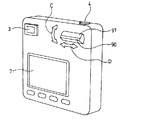
第3の実施の形態のデジタルカメラは、タッチ検出センサ90をデジタルカメラ操作用の傾動型スイッチ91の傾動部材表面に設けている。傾動型スイッチ91は、C方向に傾動操作されるもので、画像撮影時は撮影倍率を制御し、画像再生時は画像の表示倍率を変更するものである。
(Third embodiment)
In the digital camera of the third embodiment, the
タッチ検出センサ90は、接点式スイッチ群等で構成され、画像再生時の表示内容の制御に利用される。すなわち、指をタッチ検出センサ90に接触させた状態で移動させることにより、複数の撮影画像を連続的にコマ送りするものである。また、再生画像の拡大表示時には、拡大画像の表示領域の変更操作を行うものである。このとき、傾動型スイッチ91は、再生画像の表示倍率を変更するのに利用されるので、必要な領域の拡大画像を簡単な操作で表示させることができる。
The
1・・・電源スイッチ
2・・・レンズ
3・・・光学ファインダー
4・・・シャッターボタン
5・・・補助光発光部
6・・・記録メディア挿入部
7・・・画像モニタ
8、9、10・・・タッチパッド
21・・・シャッター・絞り
22・・・撮像デバイス
23・・・駆動回路
24・・・アナログ信号処理部
25・・・A/D変換部
26・・・デジタル信号処理部
27・・・出力用メモリ
28・・・圧縮伸張処理部
29・・・CPU
30・・・操作スイッチ
31・・・シャッタースイッチ
32・・・メディアインタフェース
33〜36・・・項目メニューマーク
37・・・被選択候補
60・・・フレーム境界
80・・・接点式スイッチ群
90・・・タッチ検出センサ
91・・・傾動型スイッチ
DESCRIPTION OF SYMBOLS 1 ...
30 ...
Claims (10)
線状かつ連続的に配置したタッチ検出センサを含むタッチ入力部を、前記表示装置の周辺に設け、
前記タッチ入力部が検出したタッチ位置及びタッチ状態での移動に応じて前記携帯型電子機器の制御操作又は前記表示装置に表示された項目に基づく入力操作が行われるものであり、
前記表示装置は、略矩形形状であり、
前記タッチ検出センサは、略L字状であって、前記表示装置の略直交する2辺に略平行に設けられ、
前記タッチ入力部は、前記L字の角部へのタッチ後に有効状態となる携帯型電子機器。 A portable electronic device having a display device,
A touch input unit including touch detection sensors arranged linearly and continuously is provided around the display device,
According to the touch position detected by the touch input unit and the movement in the touch state, an input operation based on the control operation of the portable electronic device or the item displayed on the display device is performed,
The display device has a substantially rectangular shape,
The touch detection sensor is substantially L-shaped and is provided substantially parallel to two substantially orthogonal sides of the display device,
The touch input unit is a portable electronic device that is enabled after touching the L-shaped corner.
前記入力操作は、前記タッチ位置に対応する項目の被選択候補が表示された後の、タッチ状態での移動位置によって行われる携帯型電子機器。 The portable electronic device according to claim 1,
The portable electronic device in which the input operation is performed according to a moving position in a touch state after a selection candidate of an item corresponding to the touch position is displayed.
前記タッチ入力部のタッチ状態での移動に応じた前記携帯型電子機器の制御操作は、前記表示装置に表示される画像の表示倍率の変更操作を含む携帯型電子機器。 The portable electronic device according to claim 1 or 2,
The control operation of the portable electronic device according to the movement of the touch input unit in a touch state includes a change operation of a display magnification of an image displayed on the display device.
前記タッチ入力部のタッチ状態での移動に応じた前記携帯型電子機器の制御操作は、前記表示装置に表示される画像の表示領域の変更操作を含む携帯型電子機器。 A portable electronic device according to any one of claims 1 to 3,
The control operation of the portable electronic device according to the movement of the touch input unit in a touch state includes a change operation of a display area of an image displayed on the display device.
前記タッチ入力部のタッチ状態での移動に応じた前記携帯型電子機器の制御操作は、前記表示装置に表示される画像の連続的なコマ送り操作を含む携帯型電子機器。 A portable electronic device according to any one of claims 1 to 4,
The control operation of the portable electronic device according to the movement of the touch input unit in a touched state includes a continuous frame advance operation of an image displayed on the display device.
前記携帯型電子機器は、デジタルカメラである携帯型電子機器。 A portable electronic device according to any one of claims 1 to 5,
The portable electronic device is a portable electronic device that is a digital camera.
前記タッチ入力部のタッチ状態での移動に応じた前記携帯型電子機器の制御操作は、撮影倍率の変更操作を含む携帯型電子機器。 The portable electronic device according to claim 6, wherein
The control operation of the portable electronic device according to the movement of the touch input unit in the touched state includes a change operation of a photographing magnification.
前記タッチ検出センサは、タッチパッドで構成される携帯型電子機器。 A portable electronic device according to any one of claims 1 to 7,
The touch detection sensor is a portable electronic device configured with a touch pad.
前記タッチ検出センサは、接点式スイッチで構成される携帯型電子機器。 A portable electronic device according to any one of claims 1 to 7,
The touch detection sensor is a portable electronic device configured with a contact switch.
前記接点式スイッチは、メンブレンスイッチである携帯型電子機器。 The portable electronic device according to claim 9, wherein
The contact-type switch is a portable electronic device that is a membrane switch.
Priority Applications (1)
| Application Number | Priority Date | Filing Date | Title |
|---|---|---|---|
| JP2008093926A JP4551945B2 (en) | 2008-03-31 | 2008-03-31 | Portable electronic devices |
Applications Claiming Priority (1)
| Application Number | Priority Date | Filing Date | Title |
|---|---|---|---|
| JP2008093926A JP4551945B2 (en) | 2008-03-31 | 2008-03-31 | Portable electronic devices |
Related Parent Applications (1)
| Application Number | Title | Priority Date | Filing Date |
|---|---|---|---|
| JP2001159136A Division JP4127982B2 (en) | 2001-05-28 | 2001-05-28 | Portable electronic devices |
Publications (2)
| Publication Number | Publication Date |
|---|---|
| JP2008236765A JP2008236765A (en) | 2008-10-02 |
| JP4551945B2 true JP4551945B2 (en) | 2010-09-29 |
Family
ID=39908911
Family Applications (1)
| Application Number | Title | Priority Date | Filing Date |
|---|---|---|---|
| JP2008093926A Expired - Lifetime JP4551945B2 (en) | 2008-03-31 | 2008-03-31 | Portable electronic devices |
Country Status (1)
| Country | Link |
|---|---|
| JP (1) | JP4551945B2 (en) |
Families Citing this family (12)
| Publication number | Priority date | Publication date | Assignee | Title |
|---|---|---|---|---|
| JP5251463B2 (en) * | 2008-12-03 | 2013-07-31 | ソニー株式会社 | Imaging device |
| JP2014013501A (en) | 2012-07-04 | 2014-01-23 | Sony Corp | Information input apparatus, information processing apparatus, and remote control system |
| JP5794709B2 (en) * | 2013-12-27 | 2015-10-14 | キヤノン株式会社 | Display control apparatus, display control apparatus control method, and program |
| JP6205068B2 (en) | 2014-09-05 | 2017-09-27 | 富士フイルム株式会社 | Operation device, operation method, and program for imaging apparatus |
| KR20190052615A (en) | 2017-11-08 | 2019-05-16 | 캐논 가부시끼가이샤 | Imaging apparatus |
| JP6591003B1 (en) | 2018-06-29 | 2019-10-16 | キヤノン株式会社 | Electronics |
| JP7071234B2 (en) * | 2018-06-29 | 2022-05-18 | キヤノン株式会社 | Electronics |
| JP7195788B2 (en) * | 2018-06-29 | 2022-12-26 | キヤノン株式会社 | Electronics |
| US10897568B2 (en) | 2018-06-29 | 2021-01-19 | Canon Kabushiki Kaisha | Electronic device |
| JP6676807B2 (en) | 2018-06-29 | 2020-04-08 | キヤノン株式会社 | Electronics |
| JP7191562B2 (en) * | 2018-06-29 | 2022-12-19 | キヤノン株式会社 | ELECTRONIC DEVICE, ELECTRONIC DEVICE CONTROL METHOD, PROGRAM AND STORAGE MEDIUM |
| JP2020009413A (en) | 2018-06-29 | 2020-01-16 | キヤノン株式会社 | Electronic device |
Citations (9)
| Publication number | Priority date | Publication date | Assignee | Title |
|---|---|---|---|---|
| JPH05207343A (en) * | 1992-01-27 | 1993-08-13 | Sony Corp | Mode selecting device for video equipment |
| JPH06208433A (en) * | 1992-11-12 | 1994-07-26 | Sextant Avionique | Terminal equipment |
| JPH104531A (en) * | 1996-06-14 | 1998-01-06 | Nikon Corp | Information processor |
| JPH11194863A (en) * | 1998-01-06 | 1999-07-21 | Poseidon Technical Systems:Kk | Touch input detecting method and touch input detector |
| JPH11212726A (en) * | 1998-01-29 | 1999-08-06 | Omron Corp | Input device |
| JPH11289484A (en) * | 1998-04-06 | 1999-10-19 | Fuji Photo Film Co Ltd | Camera with monitor |
| JP2000059553A (en) * | 1998-04-06 | 2000-02-25 | Canon Inc | Image input device and its controlling method |
| JP2000122779A (en) * | 1998-10-16 | 2000-04-28 | Sony Corp | Video image reproducing device |
| JP2001056746A (en) * | 1999-08-18 | 2001-02-27 | Funai Electric Co Ltd | Pointing device, display controller and storage medium |
-
2008
- 2008-03-31 JP JP2008093926A patent/JP4551945B2/en not_active Expired - Lifetime
Patent Citations (9)
| Publication number | Priority date | Publication date | Assignee | Title |
|---|---|---|---|---|
| JPH05207343A (en) * | 1992-01-27 | 1993-08-13 | Sony Corp | Mode selecting device for video equipment |
| JPH06208433A (en) * | 1992-11-12 | 1994-07-26 | Sextant Avionique | Terminal equipment |
| JPH104531A (en) * | 1996-06-14 | 1998-01-06 | Nikon Corp | Information processor |
| JPH11194863A (en) * | 1998-01-06 | 1999-07-21 | Poseidon Technical Systems:Kk | Touch input detecting method and touch input detector |
| JPH11212726A (en) * | 1998-01-29 | 1999-08-06 | Omron Corp | Input device |
| JPH11289484A (en) * | 1998-04-06 | 1999-10-19 | Fuji Photo Film Co Ltd | Camera with monitor |
| JP2000059553A (en) * | 1998-04-06 | 2000-02-25 | Canon Inc | Image input device and its controlling method |
| JP2000122779A (en) * | 1998-10-16 | 2000-04-28 | Sony Corp | Video image reproducing device |
| JP2001056746A (en) * | 1999-08-18 | 2001-02-27 | Funai Electric Co Ltd | Pointing device, display controller and storage medium |
Also Published As
| Publication number | Publication date |
|---|---|
| JP2008236765A (en) | 2008-10-02 |
Similar Documents
| Publication | Publication Date | Title |
|---|---|---|
| JP4127982B2 (en) | Portable electronic devices | |
| JP4551945B2 (en) | Portable electronic devices | |
| US7999872B2 (en) | Image display device, image pickup apparatus, image display control method, and program | |
| US7110040B1 (en) | Camera with monitor | |
| CN1901625B (en) | Electronic camera for capturing image as digital data | |
| JP5652652B2 (en) | Display control apparatus and method | |
| JP4956988B2 (en) | Imaging device | |
| US8884882B2 (en) | Mobile equipment with display function | |
| JP4395808B2 (en) | Operation device for apparatus having screen display unit, digital camera, and touch panel operation method | |
| JP2007158919A (en) | Image display apparatus and image display method | |
| US20120026364A1 (en) | Image pickup apparatus | |
| EP2469376A2 (en) | Image display control apparatus and image display control method | |
| JP2005303728A (en) | Digital camera | |
| JP2012010061A (en) | Imaging apparatus | |
| JP2010245843A (en) | Image display device | |
| JP2007052795A (en) | Operation device of apparatus provided with screen display part, and digital camera | |
| JP2003338954A (en) | Digital still camera | |
| JP2006344168A (en) | Image display apparatus and photographing apparatus | |
| JP2013090056A (en) | Image reproduction device and camera | |
| US9621809B2 (en) | Display control apparatus and method for controlling the same | |
| JP2007221384A (en) | Camera | |
| JP2009130636A (en) | Imaging apparatus | |
| JP2007048123A (en) | Display device | |
| JP2012233954A (en) | Electronic apparatus | |
| JP6039325B2 (en) | Imaging device, electronic device, and touch panel control method |
Legal Events
| Date | Code | Title | Description |
|---|---|---|---|
| TRDD | Decision of grant or rejection written | ||
| A01 | Written decision to grant a patent or to grant a registration (utility model) |
Free format text: JAPANESE INTERMEDIATE CODE: A01 Effective date: 20100622 |
|
| A01 | Written decision to grant a patent or to grant a registration (utility model) |
Free format text: JAPANESE INTERMEDIATE CODE: A01 |
|
| A61 | First payment of annual fees (during grant procedure) |
Free format text: JAPANESE INTERMEDIATE CODE: A61 Effective date: 20100712 |
|
| R150 | Certificate of patent or registration of utility model |
Free format text: JAPANESE INTERMEDIATE CODE: R150 Ref document number: 4551945 Country of ref document: JP Free format text: JAPANESE INTERMEDIATE CODE: R150 |
|
| FPAY | Renewal fee payment (event date is renewal date of database) |
Free format text: PAYMENT UNTIL: 20130716 Year of fee payment: 3 |
|
| R250 | Receipt of annual fees |
Free format text: JAPANESE INTERMEDIATE CODE: R250 |
|
| R250 | Receipt of annual fees |
Free format text: JAPANESE INTERMEDIATE CODE: R250 |
|
| R250 | Receipt of annual fees |
Free format text: JAPANESE INTERMEDIATE CODE: R250 |
|
| R250 | Receipt of annual fees |
Free format text: JAPANESE INTERMEDIATE CODE: R250 |
|
| R250 | Receipt of annual fees |
Free format text: JAPANESE INTERMEDIATE CODE: R250 |
|
| R250 | Receipt of annual fees |
Free format text: JAPANESE INTERMEDIATE CODE: R250 |
|
| R250 | Receipt of annual fees |
Free format text: JAPANESE INTERMEDIATE CODE: R250 |
|
| R250 | Receipt of annual fees |
Free format text: JAPANESE INTERMEDIATE CODE: R250 |
|
| EXPY | Cancellation because of completion of term |