JP2005292883A - Information input device - Google Patents
Information input device Download PDFInfo
- Publication number
- JP2005292883A JP2005292883A JP2004102591A JP2004102591A JP2005292883A JP 2005292883 A JP2005292883 A JP 2005292883A JP 2004102591 A JP2004102591 A JP 2004102591A JP 2004102591 A JP2004102591 A JP 2004102591A JP 2005292883 A JP2005292883 A JP 2005292883A
- Authority
- JP
- Japan
- Prior art keywords
- input
- information
- plate
- input device
- members
- Prior art date
- Legal status (The legal status is an assumption and is not a legal conclusion. Google has not performed a legal analysis and makes no representation as to the accuracy of the status listed.)
- Pending
Links
Images


Classifications
-
- G—PHYSICS
- G06—COMPUTING OR CALCULATING; COUNTING
- G06F—ELECTRIC DIGITAL DATA PROCESSING
- G06F3/00—Input arrangements for transferring data to be processed into a form capable of being handled by the computer; Output arrangements for transferring data from processing unit to output unit, e.g. interface arrangements
- G06F3/01—Input arrangements or combined input and output arrangements for interaction between user and computer
- G06F3/03—Arrangements for converting the position or the displacement of a member into a coded form
- G06F3/033—Pointing devices displaced or positioned by the user, e.g. mice, trackballs, pens or joysticks; Accessories therefor
- G06F3/0346—Pointing devices displaced or positioned by the user, e.g. mice, trackballs, pens or joysticks; Accessories therefor with detection of the device orientation or free movement in a three-dimensional [3D] space, e.g. 3D mice, 6-DOF [six degrees of freedom] pointers using gyroscopes, accelerometers or tilt-sensors
-
- G—PHYSICS
- G06—COMPUTING OR CALCULATING; COUNTING
- G06F—ELECTRIC DIGITAL DATA PROCESSING
- G06F3/00—Input arrangements for transferring data to be processed into a form capable of being handled by the computer; Output arrangements for transferring data from processing unit to output unit, e.g. interface arrangements
- G06F3/01—Input arrangements or combined input and output arrangements for interaction between user and computer
- G06F3/03—Arrangements for converting the position or the displacement of a member into a coded form
- G06F3/033—Pointing devices displaced or positioned by the user, e.g. mice, trackballs, pens or joysticks; Accessories therefor
-
- A—HUMAN NECESSITIES
- A63—SPORTS; GAMES; AMUSEMENTS
- A63F—CARD, BOARD, OR ROULETTE GAMES; INDOOR GAMES USING SMALL MOVING PLAYING BODIES; VIDEO GAMES; GAMES NOT OTHERWISE PROVIDED FOR
- A63F13/00—Video games, i.e. games using an electronically generated display having two or more dimensions
- A63F13/20—Input arrangements for video game devices
- A63F13/21—Input arrangements for video game devices characterised by their sensors, purposes or types
- A63F13/218—Input arrangements for video game devices characterised by their sensors, purposes or types using pressure sensors, e.g. generating a signal proportional to the pressure applied by the player
-
- A—HUMAN NECESSITIES
- A63—SPORTS; GAMES; AMUSEMENTS
- A63F—CARD, BOARD, OR ROULETTE GAMES; INDOOR GAMES USING SMALL MOVING PLAYING BODIES; VIDEO GAMES; GAMES NOT OTHERWISE PROVIDED FOR
- A63F13/00—Video games, i.e. games using an electronically generated display having two or more dimensions
- A63F13/20—Input arrangements for video game devices
- A63F13/24—Constructional details thereof, e.g. game controllers with detachable joystick handles
-
- G—PHYSICS
- G06—COMPUTING OR CALCULATING; COUNTING
- G06F—ELECTRIC DIGITAL DATA PROCESSING
- G06F3/00—Input arrangements for transferring data to be processed into a form capable of being handled by the computer; Output arrangements for transferring data from processing unit to output unit, e.g. interface arrangements
- G06F3/01—Input arrangements or combined input and output arrangements for interaction between user and computer
- G06F3/03—Arrangements for converting the position or the displacement of a member into a coded form
- G06F3/033—Pointing devices displaced or positioned by the user, e.g. mice, trackballs, pens or joysticks; Accessories therefor
- G06F3/0354—Pointing devices displaced or positioned by the user, e.g. mice, trackballs, pens or joysticks; Accessories therefor with detection of two-dimensional [2D] relative movements between the device, or an operating part thereof, and a plane or surface, e.g. 2D mice, trackballs, pens or pucks
- G06F3/03548—Sliders, in which the moving part moves in a plane
-
- A—HUMAN NECESSITIES
- A63—SPORTS; GAMES; AMUSEMENTS
- A63F—CARD, BOARD, OR ROULETTE GAMES; INDOOR GAMES USING SMALL MOVING PLAYING BODIES; VIDEO GAMES; GAMES NOT OTHERWISE PROVIDED FOR
- A63F2300/00—Features of games using an electronically generated display having two or more dimensions, e.g. on a television screen, showing representations related to the game
- A63F2300/10—Features of games using an electronically generated display having two or more dimensions, e.g. on a television screen, showing representations related to the game characterized by input arrangements for converting player-generated signals into game device control signals
- A63F2300/1043—Features of games using an electronically generated display having two or more dimensions, e.g. on a television screen, showing representations related to the game characterized by input arrangements for converting player-generated signals into game device control signals being characterized by constructional details
-
- A—HUMAN NECESSITIES
- A63—SPORTS; GAMES; AMUSEMENTS
- A63F—CARD, BOARD, OR ROULETTE GAMES; INDOOR GAMES USING SMALL MOVING PLAYING BODIES; VIDEO GAMES; GAMES NOT OTHERWISE PROVIDED FOR
- A63F2300/00—Features of games using an electronically generated display having two or more dimensions, e.g. on a television screen, showing representations related to the game
- A63F2300/10—Features of games using an electronically generated display having two or more dimensions, e.g. on a television screen, showing representations related to the game characterized by input arrangements for converting player-generated signals into game device control signals
- A63F2300/1056—Features of games using an electronically generated display having two or more dimensions, e.g. on a television screen, showing representations related to the game characterized by input arrangements for converting player-generated signals into game device control signals involving pressure sensitive buttons
Landscapes
- Engineering & Computer Science (AREA)
- Multimedia (AREA)
- Human Computer Interaction (AREA)
- General Engineering & Computer Science (AREA)
- Theoretical Computer Science (AREA)
- Physics & Mathematics (AREA)
- General Physics & Mathematics (AREA)
- Position Input By Displaying (AREA)
Abstract
Description
本発明は、情報入力装置に関するものである。 The present invention relates to an information input device.
AV機器、家電機器、産業機器、コンピュータなど、機能が多様化するにつれ、入力しなければならない情報量が増え、それに伴い情報入力装置も複雑化し人間に使い難いものになっている。例えば、テレビのリモコンをみると、数多くのボタンが配置され、さらに、モード切り替えにより一つのボタンに幾つかの機能を割り当てるために、一層わかり難いものになっている。 As functions diversify such as AV equipment, home appliances, industrial equipment, and computers, the amount of information that must be input increases, and the information input device becomes complicated and difficult for humans to use. For example, looking at the remote control of a television, a large number of buttons are arranged, and furthermore, since several functions are assigned to one button by switching modes, it is more difficult to understand.
また、GUI(Graphical User Interface)を活用した情報入力装置もあるが、必ずしも使い易いものではなく、また、表示装置の解像度に見合う操作分解能を備えた適切な情報入力装置(ポインティングデバイス等)が実用化されていないのが現状である。 There is also an information input device that utilizes GUI (Graphical User Interface), but it is not always easy to use, and an appropriate information input device (pointing device, etc.) with an operation resolution that matches the resolution of the display device is practical. The current situation is that it has not been realized.
例えば、PC等のポインティングデバイスの代表であるマウスは、操作するためのテーブルなど一定の広さの平面が必要であり、手に持った状態で自由に操作することができない。また、マウスは手首と肘を使った操作になるため微妙な操作は難しく、操作分解能の高い情報入力装置とは言い難い。また携帯型PCではタッチパネル型の情報入力装置が採用されているが、パネル自体はPCに対して固定されているので操作の自由度に欠け、また、指という大きなものの位置検出を行うものであるため、操作分解能は非常に悪く、更には指先の摩擦感が不快でもある。 For example, a mouse that is representative of a pointing device such as a PC needs a flat surface such as a table for operation, and cannot be freely operated while being held in a hand. Also, since the mouse is operated using the wrist and elbow, it is difficult to perform delicate operations, and it is difficult to say that the information input device has high operation resolution. In addition, a touch panel type information input device is employed in a portable PC, but the panel itself is fixed with respect to the PC, so that the degree of freedom of operation is lacking, and the position of a large thing such as a finger is detected. Therefore, the operation resolution is very poor, and the frictional feeling of the fingertip is uncomfortable.
これに対して、操作の自由度が高く、装置本体を手で握った状態で指先を使って操作できる情報入力装置が各種提案されている。 On the other hand, various information input devices that have a high degree of freedom of operation and can be operated using a fingertip while holding the device main body with a hand have been proposed.
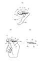
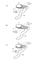
例えば、下記特許文献1に記載の従来技術を図1によって説明すると、これは、本体J1に、PC操作データを送信する送信部J2を設け、本体1を握りながら、指で入力操作ができる位置にスティックJ3を設けると共に、クリックボタンJ4,J5を取り付けているワイヤレスの入力装置である。
For example, the prior art described in
一般に、人間のもつ最も高い操作分解能は指先の操作によってもたらされると言われている。しかしながら、前述した従来技術では、装置本体を手で握った状態で固定し、それに対して一本の指で操作を行うものであるから、指先の持っている繊細な分解能を充分に引き出す構成になっていない。 In general, it is said that the highest operation resolution of humans is brought about by fingertip operations. However, in the above-described prior art, the apparatus main body is fixed with the hand held, and the operation is performed with a single finger. is not.
つまり、前述の従来技術は、親指の腹にスティックJ3の先端を当てて、親指の第一関節と第二関節を屈折したり伸ばしたりしながら入力操作を行うものであるが、このように一つの指だけを単独で動かして操作を行うことは案外操作し難く、またかなり手先の器用な人でもこのような指一本の操作で高い操作分解能を得ることはできない。 In other words, the above-described conventional technique performs an input operation while placing the tip of the stick J3 on the belly of the thumb and bending and stretching the first joint and the second joint of the thumb. It is difficult to perform an operation by moving only one finger alone, and even a dexterous person with a very short hand cannot obtain a high operation resolution with such a single finger operation.
したがって、従来技術では、可搬性を持たせることで操作自由度は向上しているが、例えば、GUIのポインティングデバイスに採用することを考えると、高精細又は広い表示画面に対応した高い操作分解能を得ることができないので、微細な位置入力を行うことができないという問題が生じる。また、一つの入力部(スティック等)に対する操作で多種類の情報入力を行おうとしても、それに対応した操作分解能が得られないので、入力できる情報の種類を少なくせざるを得ないという問題がある。 Therefore, in the prior art, the degree of freedom of operation is improved by providing portability. However, considering adopting it as a GUI pointing device, for example, high operation resolution corresponding to a high-definition or wide display screen is achieved. Since it cannot be obtained, there arises a problem that fine position input cannot be performed. In addition, even if various types of information are input by operating one input unit (such as a stick), the corresponding operation resolution cannot be obtained, and therefore the type of information that can be input must be reduced. is there.
本発明は、このような問題に対処するために提案されたものであって、可搬性を持たせることで操作自由度を向上させると共に、高い操作分解能を有する情報入力装置を提供すること、例えば、GUIの入力装置として用いる場合にも、高精細又は広い表示画面に対応して微細な位置入力が可能な情報入力装置を提供できること、或いは、多種類の情報入力を単純な入力部の操作で入力可能にすること等が本発明の目的である。 The present invention has been proposed in order to cope with such a problem, and provides an information input device having high operation resolution while improving the degree of freedom of operation by providing portability, for example, Even when used as a GUI input device, it is possible to provide an information input device capable of fine position input corresponding to a high-definition or wide display screen, or a variety of information input can be performed by a simple operation of the input unit. It is an object of the present invention to enable input.
このような目的を達成するために、本発明による情報入力装置は、以下の独立請求項に係る構成を少なくとも具備するものである。 In order to achieve such an object, an information input device according to the present invention comprises at least a configuration according to the following independent claims.
[請求項1]片手の二本の指の指先又は指の一部で挟持して相対的に摺動可能な二枚の板状入力部材と、前記片手の他の指を用いて把持される把持部と前記二枚の板状入力部材を前記把持部に連結する連結部とを備えると共に、少なくとも前記板状入力部材の相対位置又は相対移動に応じて入力情報を形成する情報形成部を備えることを特徴とする情報入力装置。 [Claim 1] Two plate-like input members which can be slid relative to each other by being sandwiched between two fingertips of one hand or a part of a finger, and are gripped using the other finger of the one hand. A gripping portion and a connecting portion for connecting the two plate-like input members to the gripping portion, and an information forming portion for forming input information according to at least the relative position or relative movement of the plate-like input member. An information input device characterized by that.
以下、本発明の実施形態を図面を参照して説明する。図2は、本発明の一実施形態に係る情報入力装置を示す説明図である(同図(a)は全体構成図、同図(b)は操作状態を示す説明図、同図(c)は板状入力部材の断面図)。 Hereinafter, embodiments of the present invention will be described with reference to the drawings. FIG. 2 is an explanatory view showing an information input device according to an embodiment of the present invention (FIG. 2 (a) is an overall configuration diagram, FIG. 2 (b) is an explanatory view showing an operation state, and FIG. 2 (c). Is a sectional view of a plate-like input member).
本発明の実施形態に係る情報入力装置は、人間の行う動作の中で指先の動作が最も分解能の高い動作であり、また、特に指先又は指の一部で物を挟持する際には、指先又は指の一部に神経が集中しやすく、人間の意志どおりに物を動かし易いという事実を利用したものであって、片手の二本の指先又は指の一部(例えば、親指の指先と人差し指の第2関節以上の先端部分)で物を挟んで摺り合わせる動作を情報入力装置の入力操作に活用したものである。 In the information input device according to the embodiment of the present invention, the movement of the fingertip is the movement with the highest resolution among the movements performed by humans, and particularly when the object is pinched by the fingertip or a part of the finger, Or it is based on the fact that nerves tend to concentrate on a part of the finger, and it is easy to move things according to the will of the human, and the two fingertips or part of the finger (for example, the thumbtip and index finger) The tip part of the second joint or higher) is used for the input operation of the information input device.
図2(a),(b)に示すように、本発明の実施形態に係る情報入力装置1は、片手の二本の指先又は指の一部で挟持して相対的に摺動可能な二枚の板状入力部材11,12と、片手の他の指を用いて把持される把持部30と、二枚の板状入力部材11,12を把持部30に連結する連結部21,22とを備えると共に、板状入力部材11,12の相対位置又は相対移動に応じて入力情報を形成する情報形成部(図示省略)を備えている。
As shown in FIGS. 2 (a) and 2 (b), the
このような基本構成を備えた情報入力装置1によると、先ず、装置自体は把持部30によって片手に把持されるので、操作の自由度が高まり操作性が向上する利点が得られる。また、二本の指の指先又は指の一部で板状入力部材11,12を挟んで擦り合わせるように操作することで、二枚の板状入力部材11,12は図2(a)の矢印方向を含むあらゆる方向に相対的に摺動可能になる(例えば、一方の板状入力部材11が他方の板状入力部材12に対して111,112のように相対的に摺動可能である)が、二本の指で挟んだ状態でこのような操作をすることによって、人間の行う操作の中で最も操作分解能の高い指先の擦り合わせ動作を利用し、しかも指先に神経が集中し易く感受性の高い状態で入力操作を行うことが可能になる。
According to the
そして、このような入力操作による板状入力部材の相対位置又は相対移動に応じて入力情報を形成する情報形成部を備えることで、例えば、GUIの入力装置として用いる場合にも、高精細又は広い表示画面に対応して微細な位置入力が可能になり、また、操作分解可能な入力操作に対応して異なる種類の情報入力を行うようにすれば、指と指とを擦り合わせるという単純な入力操作で多種類の情報を入力することが可能になる。 And by providing the information formation part which forms input information according to the relative position or relative movement of the plate-like input member by such an input operation, even when using as an input device of GUI, for example, it is high definition or wide It is possible to input a minute position corresponding to the display screen, and if different types of information are input corresponding to input operations that can be disassembled, a simple input of rubbing fingers together Various kinds of information can be input by operation.
また、二枚の板状入力部材11,12は、図2(b),(c)に示すように、対面する摺接面11a,12aとその背面側に前述の指先又は指の一部が当接する当接面11b,12bを備え、一方の当接面11bが親指の腹部に当接可能なように構成されている。更には、当接面11b,12bには、必要に応じて、指先又は指の一部との滑りを止める摩擦面が形成されている。
Further, as shown in FIGS. 2 (b) and 2 (c), the two plate-
このような構成によると、親指の腹部と他の指の一部との擦り合わせ動作(図2(b)の矢印のように、親指を他の指に対して相対的に移動させる動作)という高い感受性の得られる動作を二枚の板状入力部材11,12を介在させて行うことができ、特に、当接面11b,12bに滑り止めの摩擦面を設けることで、実際に指と指とを擦り合わせる時と同様の感覚で入力操作を行うことが可能になる。また、板状入力部材11、12の摺接面11a,12a間にグリス等の高粘度の液体を注入すると、摺動が滑らかになるとともに、ある程度の抵抗感が得られるので、より感性の高い操作を行うことが可能になる。図2(b)に示す例では、親指と人差し指の二本の指を利用しているが、これに限らず、例えば親指と中指の二本で板状入力部材11,12を挟持し、人差し指を他の入力操作等に利用するようにしてもよい。
According to such a configuration, the rubbing operation between the abdomen of the thumb and a part of another finger (the operation of moving the thumb relative to the other finger as indicated by the arrow in FIG. 2B). An operation with high sensitivity can be performed with the two plate-
本発明の実施形態に係る情報入力装置1における連結部21,22について説明すると、この連結部11,12は二枚の板状入力部材11,12を相対的に摺動可能なように把持部30に連結するものであるが、この連結部21,22は屈曲性又は弾性を有すると共に二枚の板状入力部材11,12を分離不能に保持するように構成することができる。
The connecting
これによると、自由に或いは所望の規制を受けた状態で二枚の板状入力部材11,12を相対的に摺動させることが出ると共に、板状入力部材11,12を挟持する二本の指を離した場合にも二枚の板状入力部材11,12は分離しないので、二本の指を板状入力部材11,12から離した後にも即座に入力操作に復帰することができ、高い操作性を得ることができる。
According to this, the two plate-
また、連結部21,22は、把持部30を片手で把持した状態で、二枚の板状入力部材11,12を二本の指で挟持可能な位置に保持するように構成することができる。これによると、把持部30の片手での把持と板状入力部材11,12の二本の指での挟持を自然な片手の握り状態で実現でき、操作性が楽である。また、把持部30を握った状態で板状入力部材11,12を挟持する二本の指を離した後にも、前述したように即座に入力操作に復帰することができ、高い操作性を得ることができる。
Further, the connecting
また、連結部21,22は、非挟持時に二枚の板状入力部材11,12を中立位置に復帰させる形状復帰機能を有するように構成することができる。これよると、連続して左右又は上下に板状入力部材11,12を摺動させる操作が行い易くなるので、操作性が向上する。また、入力情報の初期設定が行い易くなるという利点もある。
Moreover, the
より具体的には、連結部21,22は所望の弾性と適当な屈曲性を有するゴム等の弾性棒状又は板状入力部材によって構成することができる。弾性棒状又は板状入力部材の断面形状を工夫することによって、形状復帰機能を持たせることができる。
More specifically, the connecting
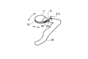
連結部21,22の形態に係る具体例を図3〜図6に示す(前述の説明と同一箇所には同一符号を付して一部重複した説明を省略する)。図3の例では、弾性板状のリブ構造を有する連結部21,22に屈曲部21a,22aを形成したものである。この例では非操作時(非挟持時)には、連結部21,22は屈曲部21a,22aで屈曲した状態になっており、これを伸ばすように操作することで板状入力部材11,12を摺動させるものである。屈曲状態への形状復帰機能を有するので前述したように高い操作性を得ることができる。
Specific examples relating to the form of the connecting
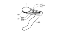
図4では、板状入力部材11を保持する連結部21を2本の弾性棒状部材21A,21Bで構成し、板状入力部材11を保持する連結部22を同様に2本の弾性棒状部材22A,22Bで構成している。
In FIG. 4, the connecting
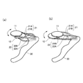
図5はその操作状態を示したものである。これによると、少なくとの1本の弾性棒状部材21A〜22Bを弾性的に屈曲させながら板状入力部材11,12間の摺動操作を行う。すなわち、同図(a)のように板状入力部材12を手前に引き寄せるようにして弾性棒状部材22A,22Bを弾性的に屈曲させるか、或いは同図(b)のように板状入力部材11を手前に引き寄せるようにして弾性棒状部材21A,21Bを弾性的に屈曲させる。また、左右一方の弾性棒状部材を屈曲させて板状入力部材11,12を互いに矢印方向に揺動させることもできる。これによると、弾性棒状部材21A〜22Bが伸びた状態に形状復帰するので、前述したように高い操作性を得ることができる。
FIG. 5 shows the operation state. According to this, the sliding operation between the plate-
図6に示す連結部21,22の例は、板状入力部材11,12の把持部30に対する位置を多段に調整できるようにしたものである。この連結部21,22は、板状入力部材11を弾性的に挟んで保持する機能を有する一対のアーム部材21C,21Dと板状入力部材12を弾性的に挟んで保持する機能を有する一対のアーム部材22C,22Dからなり、センタ位置(同図(a))から、左方向(離れた)位置(同図(b))、又は右方向(近づいた)位置(同図(c))に板状入力部材11,12を位置調整できるようにしている。また、アーム部材21C,21D或いは22C,22Dの屈曲度合いを同図(a)で安定保持する形態にすることで、センタ位置への自己復帰機能を持たせることもできる。
The example of the
これによると、操作者の指の長さ等に応じて操作しやすい位置に板状入力部材11,12の位置を調整することが可能であると共に、板状入力部材11,12と把持部30との間隔に応じて入力モードを変更するなどの態様を構成することが可能になる。
According to this, it is possible to adjust the positions of the plate-
以下に、前述した板状入力部材11,12の相対位置又は相対移動等に応じて入力情報を形成する情報形成部の例を示す。
An example of an information forming unit that forms input information according to the relative position or relative movement of the plate-
まず、情報形成部として、板状入力部材11,12の相対位置変位検出手段(センサ)を挙げることができる。本発明の実施形態に係る情報入力装置1は、GUIの入力装置として高いポインティング(位置情報の入力)性能を得るためには、できれば現在普及している表示装置の分解能程度(約千ドット)の精度をもって位置情報が入力できることが望ましい。一方、本発明の実施形態に係る情報入力装置1は、指と指の相対位置変位を利用するものでその変位の範囲は大きくない(操作性を考慮しても大きくないことが望ましい)ので、板状入力部材11,12の相対位置変位の分解能が10ミクロン以下になることが考えられる。
First, as the information forming unit, a relative position displacement detecting means (sensor) of the plate-
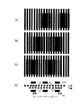
このような微細な二枚の板状入力部材11,12の相対位置変位を検出する方法の一つとして、図7にモアレ縞を用いた相対位置変位検出の実施例を示す。よく知られているように、モアレ縞は元来絹織物など細かな網目の重なりによって生じる波紋状の模様をいうが、この現象を利用すると微細な位置変位がそれよりもはるかに大きな波紋状のスケールの変化として現れるので、微小な位置変位の検出が必要な本発明の実施形態に有効である。
As one of the methods for detecting the relative position displacement of the two fine plate-
本実施例の相対位置変位検出器の構成は、光を透過する部分と光を遮断する部分が交互に縦縞状になった二枚のフィルム様のシートが、位置変位の検出対象である上下の板状入力部材11,12の摺動面11a,12aにそれぞれ配置され、それらを挟んで発光素子(LED)、受光素子(PD)がそれぞれ上下の板状入力部材11,12の中に配置されている(図7(d)参照。図では光の透過部分を白、遮断する部分を黒で表している。)。各シートにおいて、縞の透過部分と遮断部分の幅は同一であり、上側シートの縞(上縞)の幅をdu,下側のシートの幅(下幅)の幅をdlとする。
The configuration of the relative position displacement detector of the present embodiment is such that two film-like sheets in which light transmitting portions and light blocking portions are alternately formed in vertical stripes are positioned on the upper and lower sides, which are position displacement detection targets. The light-emitting elements (LEDs) and the light-receiving elements (PD) are disposed in the upper and lower plate-shaped
次に本実施例の動作を説明すると、二枚の重なった縦縞のシート(その縞の幅は上下のシートでわずかに違う)を上から見た状態が図7(a)〜(c)である(理解しやすくするため下のシートの縦幅を小さく描いている。但し、モアレの現象を視覚的に示す図のため、図7(d)との位置関係は一致していない。)。図7(a)の状態から上のシートが左方向に縞幅分だけ変位していくと(相対的には下のシートが右方向に移動するのと同じ)、重なりによるモアレ縞は(b),(c)のように変化し、例えばこのとき一番左側の受光素子(PD)に注目すると、光の透過状態(a)から半透過状態(b)を経て、遮断状態(c)になる。すなわち受光素子PDの出力電流は最大のON状態から徐々に減少し電流が流れないOFF状態に変化する。さらにシートが左に縞幅分だけ動くと、今度は出力電流がOFF状態からからON状態に変化する。 Next, the operation of the present embodiment will be described. FIGS. 7A to 7C show a state in which two overlapping vertical stripe sheets (the width of the stripe is slightly different between the upper and lower sheets) are viewed from above. Yes (for ease of understanding, the vertical width of the lower sheet is drawn small. However, since it is a diagram visually showing the moire phenomenon, the positional relationship with FIG. 7D does not match.) When the upper sheet is displaced leftward by the stripe width from the state of FIG. 7A (relatively, the lower sheet moves to the right), the moiré fringes due to the overlap are (b ), (C), for example, when attention is paid to the leftmost light receiving element (PD) at this time, the light transmission state (a) passes through the semi-transmission state (b) and then changes to the blocking state (c). Become. That is, the output current of the light receiving element PD gradually decreases from the maximum ON state and changes to the OFF state where no current flows. When the sheet further moves to the left by the stripe width, the output current changes from the OFF state to the ON state.
したがってこの電流の変化(ON→OFF、OFF→ON)の数nをカウントすると、変位距離が、(シートの縞幅)×(電流の変化の数n)によって算出できる。縞幅が例えば10ミクロンであればこの10ミクロンの単位(精度)で位置変位量が検出できることになる。 Accordingly, when the number n of the current changes (ON → OFF, OFF → ON) is counted, the displacement distance can be calculated by (sheet stripe width) × (number of current changes n). If the fringe width is 10 microns, for example, the positional displacement amount can be detected in units of 10 microns (accuracy).
この位置変位量と共に、さらに左右の移動方向を検出するため、図7(d)に示すように三組の発光素子(LED)と受光素子(PD)を設ける。中央のPDの状態(ON状態/OFF状態)とその変化する前の左右のPDのON/OFF状態と比較し、同じ状態を持っていたPDがどちら側のPDであるかによって左右の移動方向を検出する。ちなみにモアレ縞の間隔Lは、上下の縞の幅をそれぞれdu,dlとすると、その縞幅の差に反比例しており、L=dudl/│du−dl│で表され、上述の三個の受光素子と発光素子は、この半分の間隔L/2を隔てて配置される。 In order to further detect the left and right moving directions together with the amount of positional displacement, three sets of light emitting elements (LEDs) and light receiving elements (PD) are provided as shown in FIG. Compared with the state of the center PD (ON state / OFF state) and the ON / OFF state of the left and right PDs before the change, the left and right movement directions depend on which side the PD that has the same state is Is detected. Table Incidentally distance L of the Moire fringes, the width of each d u of the upper and lower fringes, in When d l, and inversely proportional to the difference between the fringe width, L = d u d l / │d u -d l │ The three light receiving elements and the light emitting elements described above are arranged with a half distance L / 2 therebetween.
以上は一つの方向(X軸とする)に関する検出について述べたが、同様にこれと直角方向(Y軸とする)の移動も上述した三組の発光、受光素子をY軸方向に配置することによって可能である。 The above description is about detection in one direction (X axis). Similarly, for the movement in the direction perpendicular to this (Y axis), the above three sets of light emitting and receiving elements are arranged in the Y axis direction. Is possible.
以上モアレ縞を利用した相対位置変位を検出する方法を説明したが、相対位置変位を検出できる方法であればこれに限られない。例えば抵抗薄膜センサやマグネスケールなども分解能があり、しかも薄いシート状で実現できるのでこの相対位置変位検出手段に適用することができる。 Although the method for detecting the relative position displacement using the moire fringes has been described above, the method is not limited to this as long as the method can detect the relative position displacement. For example, a resistance thin film sensor or a magnescale has a resolution and can be realized in a thin sheet shape, so that it can be applied to this relative position displacement detecting means.
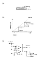
次に、情報形成部として圧力検出手段(センサ)を備えた例について図8を参照しながら説明する。図8(a)に示す圧力検出手段(センサ)13は、ここでは上側の板状入力部材11に一つ配置されている実施例を示すが、例えば下側の板状入力部材12に配置することも可能であり、また、その両方に、或いはそれぞれに複数個配置することも可能である。さらにクリック感を得るためにばね構造を設けてもよい。
Next, an example in which a pressure detection unit (sensor) is provided as an information forming unit will be described with reference to FIG. Although one example of the pressure detecting means (sensor) 13 shown in FIG. 8A is arranged on the upper plate-
この圧力センサ13は、一つにはマウスのいわゆるクリックに相当する機能(そのカーソル位置での入力指示機能)を果たすことができるものである。この動作は、短時間に摺動動作時の指圧よりも高い圧力をかけることで行うことができる。 The pressure sensor 13 can fulfill a function corresponding to a so-called click of the mouse (input instruction function at the cursor position). This operation can be performed by applying a pressure higher than the finger pressure during the sliding operation in a short time.
また、圧力センサ13には、図8(b)に示すように例えば圧電センサを使用した場合には、指で押された圧力に応じたアナログ電圧信号を、無操作時、摺動時、クリック時の3つの圧力状態に弁別して検出する機能を付与することができる。これは、クリック機能に加えて、操作(摺動)時のみ前述の相対位置検出手段からの信号を外部に送る機能を持たせるためのものであり、そのために、指を板状入力部材11に載せて摺動するときの圧力と無操作時の圧力とを区別し、無操作時の圧力では前述の相対位置検出手段からの信号を止めるという機能を付加している。
As shown in FIG. 8B, for example, when a piezoelectric sensor is used as the pressure sensor 13, an analog voltage signal corresponding to the pressure pressed by the finger is clicked when no operation is performed, when sliding. It is possible to provide a function of discriminating and detecting the three pressure states of time. This is for providing a function of sending a signal from the above-described relative position detecting means to the outside only during an operation (sliding) in addition to a click function. For this purpose, a finger is placed on the plate-
そのための回路例を図8(c)に示す。抵抗R1,R2と二つのコンパレーターからなり、抵抗R1,R2の調整で無操作状態と摺動操作状態の圧力識別、摺動操作状態とクリック状態の圧力識別の最適化を図ることができる。そして最終的に2つの出力のON,OFFの組み合わせで3状態が識別され、上述したクリック検出、相対位置変位検出信号の送出の制御等に使うことができる。もちろん、このような回路を用いず、例えば圧力センサの出力電圧をAD変換してから、デジタル的に三圧力状態を識別することもできる。 A circuit example for this purpose is shown in FIG. It consists of resistors R1 and R2 and two comparators. By adjusting the resistors R1 and R2, it is possible to optimize pressure identification between the non-operation state and the sliding operation state, and pressure identification between the sliding operation state and the click state. Finally, the three states are identified by the combination of ON and OFF of the two outputs, and can be used for the above-described click detection, control of sending the relative position displacement detection signal, and the like. Of course, without using such a circuit, for example, it is also possible to digitally identify the three pressure states after AD converting the output voltage of the pressure sensor.
上述した相対位置変位検出手段と圧力検出手段によって、マウスの機能で云えば位置情報入力機能とクリック機能を備えることができるが、次に説明する傾きセンサの採用によって、マウスの左右クリック識別機能を持たせることができる。 The above-mentioned relative position displacement detection means and pressure detection means can provide a position information input function and a click function in terms of the function of the mouse. You can have it.
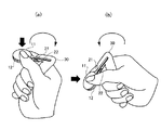
図9及び図10は、板の特定方向への傾きを検知する傾き検知手段(センサ)14を備えた実施例を示したものである。傾きセンサとしてこの例では、球14とスイッチ15を使ったものを示しているが、このスイッチ15としては近接スイッチ,光スイッチ,接触スイッチ等を使うこともできる。このセンサを備えることにより、例えば手で保持する左右の傾きを検出し、その傾き信号と、前述の圧力センサで検出したそのときのクリック信号を組み合わせることにより、二つボタンマウスのいわゆる左クリックあるいは右クリックに対応した入力が可能になる。 9 and 10 show an embodiment provided with an inclination detecting means (sensor) 14 for detecting the inclination of the plate in a specific direction. In this example, a tilt sensor using a ball 14 and a switch 15 is shown. However, as the switch 15, a proximity switch, an optical switch, a contact switch, or the like can be used. By providing this sensor, for example, the left / right tilt held by the hand is detected, and the tilt signal is combined with the click signal detected at that time by the pressure sensor, so that the so-called left click of the two-button mouse or Input corresponding to right click becomes possible.
図10は、その際の入力動作を示したものであるが、同図(a)に示すように、板状入力部材11,12を右に傾けながらクリック動作(短時間、摺動時より強い圧力を加える)を行って右クリックを実行し、同図(b)に示すように、板状入力部材11,12を左に傾けながらクリック動作を行って左クリックを実行する。
FIG. 10 shows the input operation at that time. As shown in FIG. 10 (a), while the plate-
もちろん、2つの圧力検出センサを例えば板状入力部材11の左右に2個分けて配置し、指圧の左右のセンサでの違いを検出することによっても左右クリックの検出は可能である。また、複数の圧力センサ又は分割された複数の検出部を有する大面積の圧力センサを採用すると共に、圧力状態を連続的に検出できるようにして、二次元的なカーソルの移動を検出部の選択と押圧力とによって制御するような実施例も可能である。
Of course, it is also possible to detect left and right clicks by arranging two pressure detection sensors separately on the left and right sides of the plate-
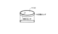
次に1次元的に動く可動部材を備えた実施例の一つとして、板状入力部材11(12)の周りに回動可能な回動リング16を備えた例を図11に示す。回動リング16はこの板状入力部材11(12)の周りを回動できる構造になっており、この回動リング16と板状入力部材11(12)との間にその相対位置変位を検出する1次元変位センサ17を配置する。これにより回動リング16の回転変位が検知され回転変位に応じた信号が出力される。すなわち、この回動リング16の位置を調整することで、それに応じた信号が外部に送出されるので、例えば対象機器の音量調整やマウスのセンターローラの役割を持たせることができる。
Next, FIG. 11 shows an example in which a rotating ring 16 that can be rotated around the plate-like input member 11 (12) is provided as one embodiment including a movable member that moves one-dimensionally. The rotating ring 16 is structured to be able to rotate around the plate-shaped input member 11 (12), and the relative position displacement is detected between the rotating ring 16 and the plate-shaped input member 11 (12). A one-
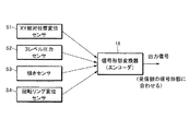
図12は,以上述べてきた各種センサ(S1〜S4)からの検出信号が信号形態変換器(エンコーダIC)18で統合され、また情報入力対象機器の信号形態(例えばUSB信号など)に適合した信号出力になるよう変換されて、外部に送信されるようすを示したブロック図である。 FIG. 12 shows that the detection signals from the various sensors (S1 to S4) described above are integrated by a signal form converter (encoder IC) 18 and adapted to the signal form (for example, USB signal) of the information input target device. It is the block diagram which showed converting as it becomes a signal output and transmitting outside.
以上、本願の実施形態に係る情報入力装置では、情報形成部の形態は前述の例に限らず各種の形態を採用することが可能である。本発明の実施形態の特徴は、このような情報形成部の形態に拘わらず、片手の指先又は指の一部で挟持して相対的に摺動可能な二枚の板状入力部材11,12と、片手の他の指を用いて把持される把持部30と、二枚の板状入力部材11,12を把持部30に連結する連結部21,22とを備え、少なくともこの板状入力部材11,12の相対位置又は相対移動に応じて入力情報を形成することにある。これによって、本発明の実施形態では、可搬性を持たせることで操作自由度を向上させることができると共に、人間の指がもつ鋭敏な感覚、優れた分解能を利用し、微細な位置入力が可能であり、また、多種類の情報入力を単純な入力部の操作で入力することが可能になる。
As described above, in the information input device according to the embodiment of the present application, the form of the information forming unit is not limited to the above example, and various forms can be adopted. The feature of the embodiment of the present invention is that the two plate-
なお、情報形成部の駆動源は、例えば、板状入力部材11,12の一方又は両方に電池(太陽電池を含む)等のエネルギ源を設置することで装備してもよいし、或いは把持部30にエネルギ源を装備して、導電性を有するか或いは配線を内蔵した連結部21,22を介して情報形成部を駆動するようにしてもよい。
In addition, the drive source of an information formation part may be equipped by installing energy sources, such as a battery (a solar cell is included), for example in one or both of the plate-shaped
把持部(グリップ)30について説明すると、その形態は図2に示すように手のひらに納まる程度の長さを有する棒状の部材で構成され、必要に応じて握り部(指の形状に対応した凹凸部)30aが形成されたものを採用することができる。そして、その一端側に連結部21,22を配備すると、図2(b)に示すように把持部30を片手で握った状態で、二本の指(例えば、親指と人差し指)で板状入力部11,12を操作することができる。
The grip portion (grip) 30 will be described. The shape of the grip portion (grip) 30 is composed of a rod-like member having a length that fits in the palm of the hand as shown in FIG. 2, and the grip portion (uneven portion corresponding to the shape of the finger) as required. ) 30a can be used. Then, when the connecting
このように把持部30を設けることで、前述したように、その内部に電池などのエネルギ源、電気回路、例えば情報入力対象機器への信号送出のための電波又は光による無線送信器等を収納できる。或いは、把持部30を握ることによって板状入力部材11,12を特定の姿勢に保持することができるので、板状入力部材11,12の動きの方向を認識しやすく、また操作の安定性が高くなる利点が得られる。
By providing the
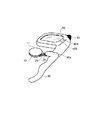
また、図13に示すように把持部30に各種の付属部品を装備させることができる。図示の例では、把持部30に小型ディスプレイ装置40を装着した例を示している。ここでは、ディスプレイ装置40に信号送信部41を設け、また補助表示装置40A,40Bを装備して、接続部40aを介して把持部30の先端部分に着脱可能な構造にしている。このようなディスプレイ装置40を備えたものでは、例えばGUIの操作をする際にも手元だけに集中して操作を行うことが可能になり、操作性及び操作精度が高まる等のメリットが生じる。また、エアコン等の装置本体自身に表示装置を持たない機器に対して情報を入力する場合にも、このディスプレイ装置40に表示した操作メニューを見ながら情報を入力するといった活用も可能である。更には、テレビや映像記録再生装置のコントローラとして用いる場合に、本体画面に操作メニューを出さないで番組選択や録画設定等ができ、見ている番組の邪魔をしないで情報入力を行うことができるという活用も可能である。
Moreover, as shown in FIG. 13, the
以上説明した本発明の実施形態に係る情報入力装置によると、可搬性を持たせることで操作自由度を向上させると共に、高い操作分解能を有する情報入力装置を提供することができる。また特に、GUIの入力装置として用いる場合に、高精細又は広い表示画面に対応して微細な位置入力が可能な情報入力装置を提供できることができる。更には、その他の入力装置として、多種類の情報を単純な操作で入力することが可能になる。 According to the information input device according to the embodiment of the present invention described above, it is possible to provide an information input device having high operation resolution while improving the degree of freedom of operation by providing portability. In particular, when used as a GUI input device, it is possible to provide an information input device capable of fine position input corresponding to a high-definition or wide display screen. Furthermore, as another input device, it is possible to input various types of information with a simple operation.
更なる効果としては、操作分解能の高い微妙な指と指との相対移動を充分な位置感度を持つセンサで感知することで、大きな動きと小さな動きをスムーズに情報に変換して出力させることができる。また、指先による動作と手先による動作を合わせた数種類の動作に対応した検知能力を持たせることができるので、持ち替えることなく多くの種類の情報を入力させることが可能になる。 As a further effect, it is possible to smoothly convert large movements and small movements into information and output them by sensing the relative movement between fingers with high operational resolution with a sensor having sufficient position sensitivity. it can. In addition, since it is possible to provide a detection capability corresponding to several types of movements including movements by the fingertips and movements by the fingertips, it is possible to input many types of information without changing them.
更には、把持部30を有することで安定した操作が得られ、また手で把持部30を持って板状入力部材11,12を指と指との相対移動で操作するものであるから、位置的な確認を目視確認することなく感覚的に得ることができる。したがって、例えばGUIの入力のような場合には、手元への視点移動を無くすことができるので操作性を著しく向上させることができる。
Further, since the gripping
1 情報入力装置
11,12 板状入力部材
11a,12a 摺接面
11b,12b 当接面
13 圧力センサ
14 球
15 スイッチ
16 回動リング
17 変位センサ
18 信号形態変換器
21,22 連結部
30 把持部
40 ディスプレイ
40A,40B 補助表示装置
41 信号送信部
DESCRIPTION OF
Claims (11)
少なくとも前記板状入力部材の相対位置又は相対移動に応じて入力情報を形成する情報形成部を備えることを特徴とする情報入力装置。 Two plate-like input members that can be slid relative to each other by being sandwiched between two fingertips or a part of a finger of one hand; a gripping part that is gripped using the other finger of the one hand; and A connecting portion for connecting two plate-like input members to the gripping portion,
An information input device comprising an information forming unit that forms input information in accordance with at least the relative position or relative movement of the plate-like input member.
Priority Applications (2)
| Application Number | Priority Date | Filing Date | Title |
|---|---|---|---|
| JP2004102591A JP2005292883A (en) | 2004-03-31 | 2004-03-31 | Information input device |
| US11/094,486 US20050219355A1 (en) | 2004-03-31 | 2005-03-31 | Information input device |
Applications Claiming Priority (1)
| Application Number | Priority Date | Filing Date | Title |
|---|---|---|---|
| JP2004102591A JP2005292883A (en) | 2004-03-31 | 2004-03-31 | Information input device |
Publications (1)
| Publication Number | Publication Date |
|---|---|
| JP2005292883A true JP2005292883A (en) | 2005-10-20 |
Family
ID=35053813
Family Applications (1)
| Application Number | Title | Priority Date | Filing Date |
|---|---|---|---|
| JP2004102591A Pending JP2005292883A (en) | 2004-03-31 | 2004-03-31 | Information input device |
Country Status (2)
| Country | Link |
|---|---|
| US (1) | US20050219355A1 (en) |
| JP (1) | JP2005292883A (en) |
Cited By (2)
| Publication number | Priority date | Publication date | Assignee | Title |
|---|---|---|---|---|
| JP2009066163A (en) * | 2007-09-12 | 2009-04-02 | Hiroshima Univ | Medical instruments |
| JP2010526387A (en) * | 2007-05-07 | 2010-07-29 | スー キム、ヨン | mouse |
Families Citing this family (14)
| Publication number | Priority date | Publication date | Assignee | Title |
|---|---|---|---|---|
| US7699757B2 (en) * | 2006-12-05 | 2010-04-20 | Cardiogrip Iph, Inc. | Apparatus, system and method for carrying out protocol-based isometric exercise regimen |
| US8669935B2 (en) * | 2009-09-17 | 2014-03-11 | Sony Corporation | Operation device |
| US11064910B2 (en) | 2010-12-08 | 2021-07-20 | Activbody, Inc. | Physical activity monitoring system |
| US10102345B2 (en) | 2012-06-19 | 2018-10-16 | Activbody, Inc. | Personal wellness management platform |
| US10133849B2 (en) | 2012-06-19 | 2018-11-20 | Activbody, Inc. | Merchandizing, socializing, and/or gaming via a personal wellness device and/or a personal wellness platform |
| US9230064B2 (en) * | 2012-06-19 | 2016-01-05 | EZ as a Drink Productions, Inc. | Personal wellness device |
| CN103529762B (en) * | 2013-02-22 | 2016-08-31 | Tcl集团股份有限公司 | A kind of intelligent home furnishing control method based on sensor technology and system |
| US9229476B2 (en) | 2013-05-08 | 2016-01-05 | EZ as a Drink Productions, Inc. | Personal handheld electronic device with a touchscreen on a peripheral surface |
| US9262064B2 (en) | 2013-07-09 | 2016-02-16 | EZ as a Drink Productions, Inc. | Handheld computing platform with integrated pressure sensor and associated methods of use |
| US10124246B2 (en) | 2014-04-21 | 2018-11-13 | Activbody, Inc. | Pressure sensitive peripheral devices, and associated methods of use |
| CN110520822B (en) | 2017-04-27 | 2023-06-27 | 索尼互动娱乐股份有限公司 | Control device, information processing system, control method, and program |
| US11130050B2 (en) * | 2017-10-16 | 2021-09-28 | Sony Interactive Entertainment Inc. | Information processing system, controller device, and information processing apparatus |
| JP6932267B2 (en) * | 2018-08-21 | 2021-09-08 | 株式会社ソニー・インタラクティブエンタテインメント | Controller device |
| CN211132974U (en) * | 2019-09-04 | 2020-07-31 | 富港电子(昆山)有限公司 | Game handle |
Family Cites Families (8)
| Publication number | Priority date | Publication date | Assignee | Title |
|---|---|---|---|---|
| DE69120491T2 (en) * | 1990-09-18 | 1996-11-14 | Fujitsu Ltd | Cursor shift control device for a computer display |
| US5432530A (en) * | 1991-05-15 | 1995-07-11 | Fujitsu Limited | Pointing device and method of control of same |
| US5666138A (en) * | 1994-11-22 | 1997-09-09 | Culver; Craig F. | Interface control |
| JPH10207616A (en) * | 1997-01-20 | 1998-08-07 | Sharp Corp | Input device |
| US6256011B1 (en) * | 1997-12-03 | 2001-07-03 | Immersion Corporation | Multi-function control device with force feedback |
| US6300938B1 (en) * | 1998-04-13 | 2001-10-09 | Immersion Corporation | Multiple-cylinder control device for computers and other electronic apparatus |
| US6580420B1 (en) * | 2000-03-15 | 2003-06-17 | Yanqing Wang | Convertible computer input device |
| KR20040027294A (en) * | 2003-07-02 | 2004-04-01 | 포스텍전자주식회사 | Sliding hinge apparatus |
-
2004
- 2004-03-31 JP JP2004102591A patent/JP2005292883A/en active Pending
-
2005
- 2005-03-31 US US11/094,486 patent/US20050219355A1/en not_active Abandoned
Cited By (2)
| Publication number | Priority date | Publication date | Assignee | Title |
|---|---|---|---|---|
| JP2010526387A (en) * | 2007-05-07 | 2010-07-29 | スー キム、ヨン | mouse |
| JP2009066163A (en) * | 2007-09-12 | 2009-04-02 | Hiroshima Univ | Medical instruments |
Also Published As
| Publication number | Publication date |
|---|---|
| US20050219355A1 (en) | 2005-10-06 |
Similar Documents
| Publication | Publication Date | Title |
|---|---|---|
| JP2005292883A (en) | Information input device | |
| JP5215383B2 (en) | mouse | |
| JP4099450B2 (en) | Gloves computer mouse | |
| US7081883B2 (en) | Low-profile multi-channel input device | |
| WO2012162000A3 (en) | Haptic device for manipulator and vehicle control | |
| TW201224867A (en) | Wearable mouse | |
| CN111527470A (en) | Active stylus | |
| KR100802456B1 (en) | Fixed mouse | |
| US20050264522A1 (en) | Data input device | |
| JP4588496B2 (en) | Information input device and information input method | |
| KR20170091959A (en) | Smart glove which is connected with smart device by bluetooth wireless communication | |
| JP4366246B2 (en) | Information input device | |
| EP1868067A1 (en) | Input device for computer | |
| KR100919237B1 (en) | Mouse for both fixed and movable usage | |
| KR20080005077U (en) | Grip type mouse | |
| KR101632841B1 (en) | Mouse | |
| US9182841B2 (en) | Input apparatus | |
| JP4265376B2 (en) | Input device and electronic device | |
| JP2004078839A (en) | Pointing device | |
| JP3052618U (en) | Hand-held control device | |
| KR20250127256A (en) | How to connect a portable controller and an XR device | |
| KR19980064767U (en) | Pointing device with a ring shape | |
| TW200825845A (en) | Finger-operated input device | |
| CN116888565A (en) | Controllers and computers | |
| JP2021064195A (en) | Pointing device and electronic apparatus |
Legal Events
| Date | Code | Title | Description |
|---|---|---|---|
| A621 | Written request for application examination |
Free format text: JAPANESE INTERMEDIATE CODE: A621 Effective date: 20070215 |
|
| A131 | Notification of reasons for refusal |
Free format text: JAPANESE INTERMEDIATE CODE: A131 Effective date: 20081128 |
|
| A02 | Decision of refusal |
Free format text: JAPANESE INTERMEDIATE CODE: A02 Effective date: 20090410 |