JP2005292879A - Imaging information server and imaging information transmission system - Google Patents
Imaging information server and imaging information transmission system Download PDFInfo
- Publication number
- JP2005292879A JP2005292879A JP2004102546A JP2004102546A JP2005292879A JP 2005292879 A JP2005292879 A JP 2005292879A JP 2004102546 A JP2004102546 A JP 2004102546A JP 2004102546 A JP2004102546 A JP 2004102546A JP 2005292879 A JP2005292879 A JP 2005292879A
- Authority
- JP
- Japan
- Prior art keywords
- unit
- information
- state change
- priority
- transmission
- Prior art date
- Legal status (The legal status is an assumption and is not a legal conclusion. Google has not performed a legal analysis and makes no representation as to the accuracy of the status listed.)
- Pending
Links
Images

Classifications
-
- G—PHYSICS
- G08—SIGNALLING
- G08B—SIGNALLING SYSTEMS, e.g. PERSONAL CALLING SYSTEMS; ORDER TELEGRAPHS; ALARM SYSTEMS
- G08B13/00—Burglar, theft or intruder alarms
- G08B13/18—Actuation by interference with heat, light, or radiation of shorter wavelength; Actuation by intruding sources of heat, light, or radiation of shorter wavelength
- G08B13/189—Actuation by interference with heat, light, or radiation of shorter wavelength; Actuation by intruding sources of heat, light, or radiation of shorter wavelength using passive radiation detection systems
- G08B13/194—Actuation by interference with heat, light, or radiation of shorter wavelength; Actuation by intruding sources of heat, light, or radiation of shorter wavelength using passive radiation detection systems using image scanning and comparing systems
- G08B13/196—Actuation by interference with heat, light, or radiation of shorter wavelength; Actuation by intruding sources of heat, light, or radiation of shorter wavelength using passive radiation detection systems using image scanning and comparing systems using television cameras
- G08B13/19678—User interface
- G08B13/19691—Signalling events for better perception by user, e.g. indicating alarms by making display brighter, adding text, creating a sound
- G08B13/19693—Signalling events for better perception by user, e.g. indicating alarms by making display brighter, adding text, creating a sound using multiple video sources viewed on a single or compound screen
-
- G—PHYSICS
- G08—SIGNALLING
- G08B—SIGNALLING SYSTEMS, e.g. PERSONAL CALLING SYSTEMS; ORDER TELEGRAPHS; ALARM SYSTEMS
- G08B13/00—Burglar, theft or intruder alarms
- G08B13/18—Actuation by interference with heat, light, or radiation of shorter wavelength; Actuation by intruding sources of heat, light, or radiation of shorter wavelength
- G08B13/189—Actuation by interference with heat, light, or radiation of shorter wavelength; Actuation by intruding sources of heat, light, or radiation of shorter wavelength using passive radiation detection systems
- G08B13/194—Actuation by interference with heat, light, or radiation of shorter wavelength; Actuation by intruding sources of heat, light, or radiation of shorter wavelength using passive radiation detection systems using image scanning and comparing systems
- G08B13/196—Actuation by interference with heat, light, or radiation of shorter wavelength; Actuation by intruding sources of heat, light, or radiation of shorter wavelength using passive radiation detection systems using image scanning and comparing systems using television cameras
- G08B13/19654—Details concerning communication with a camera
- G08B13/19656—Network used to communicate with a camera, e.g. WAN, LAN, Internet
-
- G—PHYSICS
- G08—SIGNALLING
- G08B—SIGNALLING SYSTEMS, e.g. PERSONAL CALLING SYSTEMS; ORDER TELEGRAPHS; ALARM SYSTEMS
- G08B13/00—Burglar, theft or intruder alarms
- G08B13/18—Actuation by interference with heat, light, or radiation of shorter wavelength; Actuation by intruding sources of heat, light, or radiation of shorter wavelength
- G08B13/189—Actuation by interference with heat, light, or radiation of shorter wavelength; Actuation by intruding sources of heat, light, or radiation of shorter wavelength using passive radiation detection systems
- G08B13/194—Actuation by interference with heat, light, or radiation of shorter wavelength; Actuation by intruding sources of heat, light, or radiation of shorter wavelength using passive radiation detection systems using image scanning and comparing systems
- G08B13/196—Actuation by interference with heat, light, or radiation of shorter wavelength; Actuation by intruding sources of heat, light, or radiation of shorter wavelength using passive radiation detection systems using image scanning and comparing systems using television cameras
- G08B13/19695—Arrangements wherein non-video detectors start video recording or forwarding but do not generate an alarm themselves
Landscapes
- Engineering & Computer Science (AREA)
- Physics & Mathematics (AREA)
- General Physics & Mathematics (AREA)
- Multimedia (AREA)
- Human Computer Interaction (AREA)
- Closed-Circuit Television Systems (AREA)
- Alarm Systems (AREA)
- Selective Calling Equipment (AREA)
Abstract
【課題】 監視対象に関しての状況変化に連動して、ネットワークに送出すべき映像情報を構成することにより、現実の運用状況に即した映像情報を供給しながらネットワークの帯域の有効利用を図ることができるようにする。
【解決手段】 監視対象についての撮影情報を複数種類取り込み、前記取り込んだ撮影情報を、ネットワークを介して監視局へ送出する撮影情報サーバであって、前記複数種類の撮影情報にかかる監視対象についての状態変化の発生有無をそれぞれ判定する判定部16aと、該判定部16aにて前記状態変化の発生有りと判定された監視対象についての撮影情報を、前記状態変化の発生無しと判定された監視対象についての撮影情報に優先して、前記監視局へ送出する優先送出部16bとをそなえるように構成する。
【選択図】 図1PROBLEM TO BE SOLVED: To make effective use of network bandwidth while supplying video information in accordance with an actual operation situation by configuring video information to be transmitted to a network in conjunction with a change in a situation regarding a monitoring target. It can be so.
A shooting information server that captures a plurality of types of shooting information about a monitoring target and sends the captured shooting information to a monitoring station via a network, the monitoring information regarding the plurality of types of shooting information about the monitoring target. A determination unit 16a that determines whether or not a state change has occurred, and imaging information about the monitoring target that is determined by the determination unit 16a as having the occurrence of the state change. A priority transmission unit 16b for transmission to the monitoring station is provided in preference to the imaging information for the above.
[Selection] Figure 1
Description
本発明は、監視用の映像を遠隔してモニタする際に用いて好適の、撮影情報サーバおよび撮影情報送信システムに関するものである。 The present invention relates to a photographic information server and a photographic information transmission system, which are preferably used when remotely monitoring video images for monitoring.
近年、犯罪の多発化により街中や商店街,学校もしくは重要設備,敷地などの防犯を目的として、これらの場所ないし設備を監視対象として、その映像をカメラで撮影し、監視対象から隔離された場所においてモニタでリアルタイム(実時間)に監視するという撮影情報の送信システムに対してのニーズが増えてきている。一方で、ブロードバンドインターネットサービスの普及や大容量イントラネット整備などが着々と進んできている。こうしたことを背景に、IP(Internet Protocol)ネットワークを用いた画像による監視システムの導入が増えてきている。 In recent years, due to the frequent occurrence of crimes, for the purpose of crime prevention in towns, shopping streets, schools or important facilities, sites, etc., these locations or facilities are monitored, and the video is taken with a camera and isolated from the monitored targets Therefore, there is an increasing need for a transmission system for photographing information that is monitored in real time on a monitor. On the other hand, the spread of broadband Internet services and the development of large-capacity intranets are steadily progressing. Against this background, the introduction of image monitoring systems using an IP (Internet Protocol) network is increasing.
図16は、IP伝送路を活用し遠隔画像監視を行なう撮影情報送信システム100の一般的な構成例を示すものである。この図16に示すシステム100は、遠隔から監視対象の映像を送信する被監視局110,被監視局110からの監視対象の映像をモニタすることを通じて、監視対象を監視する監視局120およびこれらの被監視局110および監視局120間を結ぶIPネットワーク130をそなえて構成されている。
FIG. 16 shows a general configuration example of the imaging
ここで、被監視局110は、監視対象となる場所の映像を撮影する例えば4台のカメラ101〜104をそなえるとともに、カメラサーバ106およびルータ107をそなえて構成されている。更に、カメラ101〜104のうちで、カメラ101〜103を固定カメラとする一方、一部のカメラ(例えばカメラ104)を、監視局120からの制御情報によりカメラサーバ106を介して撮影姿勢を可動制御しうる可動カメラとする。
Here, the monitored
また、カメラサーバ106は、カメラ101〜104で撮影された映像情報をIPパケットに変換してIPネットワーク130へ送出する機能と、監視局120からの制御情報等をIPネットワーク130経由で受信してカメラ101〜104に伝達する機能と、をそなえている。又、ルータ107は、カメラサーバ106からのIPパケットをIPネットワーク130へ送出するとともに、IPネットワーク130を通じて伝送されてきたカメラサーバ106宛てのIPパケットをカメラサーバ106へ出力する。
The
さらに、監視局120においては、被監視局110からIPネットワーク130を介して送られてきた映像情報を受信して、監視画像としてディスプレイ等を通じて表示することができるようになっている。このため、監視局120は、ディスプレイ121a付きの端末装置121と、端末装置121からのIPパケットをIPネットワーク130へ送出するとともにIPネットワーク130からのIPパケットを端末装置121に出力するルータ122とをそなえている。
Further, the
また、この監視局120においては、カメラサーバ106に対して上述のごとく制御情報をIPパケットとして送信して、これを受けたカメラサーバ106においては適宜カメラ104の動作状態を制御することができる。尚、監視局120においては、被監視局110として複数の被監視局を収容する構成とすることもできる。
画像情報は、一般的に情報量が大きいため、上述のごとき撮影情報送信システム100においては、通常は画像圧縮技術などにより情報を圧縮し伝送を行なう。そして、この情報を伝送するために必要な帯域を確保できるように、ネットワーク設計時に十分な容量のネットワークとしての伝送路をあらかじめ確保しておくことが必要である。
In addition, the
Since image information generally has a large amount of information, in the photographing
なお、本願発明に関連する公知技術としては、以下に示す特許文献1に記載されたものがある。この特許文献1には、動画情報が得られてから複数のクライアントに配信される時間を短縮可能とするために、IPエンコーダにおいてカメラからの動画情報を一旦蓄積することなく圧縮符号化しパケット化してマルチキャストすることができるようにし、更に、動画情報を収集し蓄積する動画サーバと、動画サーバに対する配信要求を受け取り配信処理を実行する管理装置とをそなえて、動画サーバでは必要な映像のみを蓄積するようにしてネットワークを効率的に利用できるようにしたネットワークシステムについて記載れている。
しかしながら、上述のごとき一般的な撮影情報送信システム100においては、画像圧縮技術により画像を圧縮して伝送しても、監視状況の事情から利用者が精細な画像品質を必要としている場合や、被監視箇所数が多い場合には、大容量の伝送路が常に必要となってしまうため、相当容量のネットワークを確保しておく必要がある反面、現実の運用においては、複数拠点を同時に精細な映像で監視する必要がない場合が多いため、ネットワーク帯域を有効に活用することができないという課題がある。
However, in the general photographing
また、特許文献1に記載された技術においても、監視対象に関して状況変化が生じた場合に精細な画像品質を必要とするような監視対象に対しては、画像圧縮技術により画像を圧縮して伝送しても、リアルタイムな監視を行なうには大容量の伝送路が常に必要となるため、上述の撮影情報送信システム100の場合と同様の課題がある。
本発明は、このような課題に鑑み創案されたもので、監視対象に関しての状況変化に連動して、ネットワークに送出すべき映像情報を構成することにより、現実の運用状況に即した映像情報を供給しながらネットワークの帯域の有効利用を図ることができるようにした、撮影情報サーバおよび撮影情報送信システムを提供することを目的とする。
Also, in the technique described in
The present invention was devised in view of such a problem, and by composing the video information to be sent to the network in conjunction with the change of the situation regarding the monitoring target, the video information in accordance with the actual operation situation is obtained. It is an object of the present invention to provide a photographing information server and a photographing information transmission system capable of effectively using a network bandwidth while being supplied.
このため、本発明の撮影情報サーバは、監視対象についての撮影情報を複数種類取り込み、前記取り込んだ撮影情報を、ネットワークを介して監視局へ送出する撮影情報サーバであって、前記複数種類の撮影情報にかかる監視対象についての状態変化の発生有無をそれぞれ判定する判定部と、該判定部にて前記状態変化の発生有りと判定された監視対象についての撮影情報を、前記状態変化の発生無しと判定された監視対象についての撮影情報に優先して、前記監視局へ送出する優先送出部と、をそなえて構成されたことを特徴としている。 For this reason, the imaging information server of the present invention is a imaging information server that captures a plurality of types of imaging information about a monitoring target and sends the captured imaging information to a monitoring station via a network. A determination unit that determines whether or not a state change has occurred with respect to the monitoring target related to the information, and shooting information about the monitoring target that is determined by the determination unit as having the occurrence of the state change is referred to as no occurrence of the state change. It is characterized in that it comprises a priority transmission section for transmitting to the monitoring station in preference to the imaging information regarding the determined monitoring target.
この場合においては、好ましくは、各監視対象の状態変化を検出する外部センサがそなえられ、該判定部を、該外部センサからの検出情報をもとに、前記状態変化の発生有無を判定するセンサ情報判定部をそなえて構成する。
または、該判定部が、前記複数の監視対象ごとに取り込まれた撮影情報のフレーム差分を演算するフレーム差分演算部と、該フレーム差分演算部における前記フレーム差分の演算結果をもとに、前記状態変化の発生有無を判定するフレーム差分判定部と、をそなえて構成する。
In this case, preferably, an external sensor for detecting a state change of each monitoring target is provided, and the determination unit determines whether or not the state change has occurred based on detection information from the external sensor. An information determination unit is provided.
Alternatively, the determination unit calculates a frame difference calculation unit that calculates a frame difference of the imaging information captured for each of the plurality of monitoring targets, and the state based on the calculation result of the frame difference in the frame difference calculation unit. And a frame difference determination unit that determines whether or not a change has occurred.
または、該判定部を、前記監視局から特定の撮影情報についての送信環境の設定を受け付ける送信環境設定受付部と、該送信環境設定受付部にて受け付けられた前記送信環境の設定をもとに、前記状態変化の発生有無を判定する優先要求判定部と、をそなえて構成する。
さらに、該優先送出部を、該判定部にて前記状態変化の発生有りと判定された監視対象についての撮影情報について、画質を高めて送出する画質制御送出部をそなえて構成することとしてもよい。
Alternatively, based on the transmission environment setting reception unit that receives a transmission environment setting for specific shooting information from the monitoring station and the transmission environment setting received by the transmission environment setting reception unit. And a priority request determination unit for determining whether or not the state change has occurred.
Furthermore, the priority sending unit may be configured to include an image quality control sending unit that sends out the image quality of the monitoring information about the monitoring target that has been determined by the judging unit as having undergone the state change. .
また、該優先送出部を、該判定部にて前記状態変化の発生有りと判定された監視対象についての撮影情報から、優先処理情報が付与されたパケットを生成する優先パケット生成部をそなえて構成することとしてもよい。
さらに、該優先送出部を、該判定部にて前記状態変化の発生有りと判定された監視対象についての撮影情報を送出するための前記ネットワークの帯域を確保する制御を行なう帯域確保制御部をそなえて構成することとしてもよい。
In addition, the priority transmission unit includes a priority packet generation unit that generates a packet to which priority processing information is added from shooting information about a monitoring target that is determined to have undergone the state change by the determination unit. It is good to do.
Further, the priority transmission unit includes a bandwidth securing control unit that performs control to secure the network bandwidth for transmitting the imaging information about the monitoring target determined by the determination unit as having the occurrence of the state change. It is good also as comprising.
さらに、該優先送出部を、該判定部にて前記状態変化の発生無しと判定された監視対象についての撮影情報の送出を停止させるとともに、該判定部にて前記状態変化の発生有りと判定された監視対象についての撮影情報を送出する撮影情報選択送出部をそなえて構成することとしてもよい。
また、好ましくは、撮影情報サーバは、該優先送出部における前記優先送出を終了させる終了制御部をそなえることもできる。
Further, the priority transmission unit stops transmission of imaging information for the monitoring target determined by the determination unit as having no occurrence of the state change, and the determination unit determines that the state change has occurred. Further, a photographing information selection / transmission unit that sends photographing information about the monitoring target may be provided.
Preferably, the imaging information server may include an end control unit that terminates the priority transmission in the priority transmission unit.
さらに、本発明の撮影情報送信システムは、監視対象についての映像を撮影する複数の撮影装置と、該撮影装置にて撮影された映像を監視用に受信する監視局と、各撮影装置にて撮影された撮影情報を取り込み、前記取り込んだ撮影情報を、ネットワークを介して該監視局へ送出する撮影情報サーバとをそなえ、該撮影情報サーバが、各撮影装置にて撮影された撮影情報にかかる監視対象についての状態変化の発生有無をそれぞれ判定する判定部と、該判定部にて前記状態変化の発生有りと判定された監視対象についての撮影情報を、前記状態変化の発生無しと判定された監視対象についての撮影情報に優先して、前記監視局へ送出する優先送出部と、をそなえて構成されたことを特徴としている。 Furthermore, the imaging information transmission system of the present invention includes a plurality of imaging devices that capture images of a monitoring target, a monitoring station that receives images captured by the imaging devices for monitoring, and imaging by each imaging device. A photographing information server that captures the captured photographing information and sends the captured photographing information to the monitoring station via a network, and the photographing information server monitors the photographing information photographed by each photographing device. A determination unit that determines whether or not a state change has occurred with respect to the object, and monitoring information that has been determined as having no occurrence of the state change with respect to the monitoring information determined by the determination unit that the state change has occurred It is characterized by comprising a priority transmission unit for transmitting to the monitoring station in preference to imaging information about the object.
このように、本発明によれば、撮影情報サーバが、優先送出部により、判定部で状態変化の発生有りと判定された監視対象についての撮影情報を、状態変化の発生無しと判定された監視対象についての撮影情報に優先して、監視局へ送出することができるので、監視対象についてのリアルタイム(実時間)での遠隔監視を実現しつつ、監視対象に関しての状況変化に連動して、ネットワークに送出すべき映像情報を構成することができ、運用状況に即した映像情報を供給しつつ状態変化の発生ありとされた重要な監視対象についての撮影情報を、ネットワーク帯域の有効利用を図りながら、確実に送出することができる利点がある。 As described above, according to the present invention, the imaging information server uses the priority transmission unit to monitor the imaging information about the monitoring target determined by the determination unit as having the occurrence of the state change. Since it can be sent to the monitoring station in preference to the shooting information about the target, real-time (real-time) remote monitoring of the monitoring target is realized, and the network is linked to the change in the status of the monitoring target. The video information to be sent to the network can be configured, and the video information for the important monitoring target that is considered to have undergone a state change while supplying the video information according to the operation status, while making effective use of the network bandwidth There is an advantage that it can be surely sent out.
以下、図面を参照することにより、本発明の実施の形態について説明する。
〔A〕本実施形態にかかる撮影情報送信システムの全体構成の説明
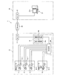
図1は本発明の一実施形態にかかる撮影情報送信システム1を示すブロック図であり、この図1に示す撮影情報送信システム1においても、街中や商店街,学校もしくは重要設備,敷地などの防犯を目的として、これらの場所ないし設備を監視対象として、その映像をカメラで撮影し、監視対象から隔離された場所においてモニタで監視するシステムとして適用することができるものである。
Hereinafter, embodiments of the present invention will be described with reference to the drawings.
[A] Description of Overall Configuration of Shooting Information Transmission System According to this Embodiment FIG. 1 is a block diagram showing a shooting
そして、この図1に示す撮影情報送信システム1においても、前述の図16の場合と同様、遠隔から監視対象の映像を送信する被監視局10,被監視局10からの監視対象の映像をモニタすることを通じて、監視対象を監視する監視局20およびこれらの被監視局10および監視局20間を結ぶIPネットワーク30をそなえて構成されている。
たとえば、被監視局10を無人通信機械室とすれば、監視対象としては、通信機械の作動状態を示す計器盤やランプ等のほか、機械室内への入室している人の状況などとすることができる。このような無人施設等を被監視局10とすれば、IPネットワーク30を通じて隔離された地点に配置される監視局20において、ディスプレイ表示等を通じて有人監視を行なうことができる。
Also in the photographing
For example, if the monitored
ここで、被監視局10は、監視対象についての映像をそれぞれ撮影する複数の撮影装置11〜14と、各撮影装置11〜14にて撮影された撮影情報を取り込み、取り込んだ撮影情報を、IPネットワーク30を介して監視局20へ送出するカメラサーバ(撮影情報サーバ)16と、前述の図16に示すもの(符号107参照)と同様のルータ17をそなえて構成されている。この撮影装置11〜14としては、例えば動画撮影を行ないうる動画カメラとすることができ、加えて、監視局20からの制御情報に基づいて姿勢を変えることができる可動カメラとすることもできる。尚、本実施形態においては、撮影装置11〜13を固定カメラとし、撮影装置14を可動カメラとしている。
Here, the monitored
さらに、監視局20は、カメラサーバ16からIPネットワーク30を介して伝送されてきた、撮影装置11〜14にて撮影された映像を、監視用に受信するものであり、前述の図16に示すもの(符号121,122参照)と同様の端末装置21およびルータ22をそなえて構成されている。
なお、監視局20においては、前述の図16の場合と同様、被監視局10と同様のものを複数収容する構成として、一つの監視局20において、複数の被監視局10について集中監視を行なうことができるようになっている。以下においては、説明の便宜ため、単一の被監視局10について図示している。
Further, the
As in the case of FIG. 16 described above, the
さらに、カメラサーバ16は、本願発明の特徴的な機能を有するもので、その機能に着目すると、撮影装置11〜14にてそれぞれ撮影された撮影情報にかかる監視対象についての状態変化(イベント)の発生有無をそれぞれ判定する判定部16aと、判定部16aにて状態変化の発生有りと判定された監視対象についての撮影情報を、状態変化の発生無しと判定された監視対象についての撮影情報に優先して、監視局20へ送出する優先送出部16bと、優先送出部16bにおける優先送出を終了させる終了制御部16cと、をそなえて構成されている。
Furthermore, the
これにより、カメラサーバ16においては、監視対象についての状態変化を判定部16aで判定し、その判定結果に応じて、優先送出部16bが、動的にネットワーク30の帯域利用を選択して、少ない帯域を有効に利用することができるようになっている。
すなわち、状態変化が検出されない通常時においては、IPネットワーク30においては比較的狭い帯域を利用して、撮影装置11〜14で撮影された全ての映像情報を合成して伝送するとともに、状態変化が検出された場合においては、IPネットワーク30においては比較的広い帯域を利用して、当該状態変化が検出された監視対象にかかる撮影装置11〜14の撮影情報を優先的に伝送することができるのである。
Thereby, in the
That is, in a normal time when no state change is detected, the
なお、図1中においては、判定部16aにおける第1態様にかかる状態変化検出を行なうための、各撮影装置11〜14近傍にそなえられた外部センサ15−1〜15−4をそについても図示されている。この外部センサ15−1〜15−4により、各撮影装置11〜14で撮影する監視対象に関しての状態変化に関わる検知出力(例えば、音の検知出力や、監視対象におけるドア開閉の検知出力等)を得ることができるようになっている。
In FIG. 1, external sensors 15-1 to 15-4 provided in the vicinity of the photographing
また、上述の撮影装置11〜14が撮影する監視対象としては、それぞれ別個のものを監視対象として撮影することとしてもよいし、同一の監視対象についてそれぞれ異なる角度から撮影したものとしてもよい。例えば、撮影装置11〜14においては、商店街等における複数地点を監視対象としてそれぞれ撮影することができる。又、敷地境界周辺を監視対象として撮影する場合においては、同一地点を複数の位置に設けられた撮影装置11〜14から撮影することもできる。
Moreover, as the monitoring object which the above-mentioned imaging devices 11-14 image | photograph, it is good also as image | photographing each different thing as a monitoring object, and good also as what image | photographed from the different angles about the same monitoring object. For example, in the
ついで、上述のカメラサーバ16の要部構成について説明する。
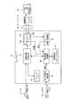
図2は本実施形態にかかるカメラサーバ16の要部構成を示すブロック図であり、この図2に示すカメラサーバ16は、撮影装置11〜14で撮影された動画像情報をフレームごとに合成された静止画情報として、IPパケット形式で順次伝送するものであって、画像圧縮符号化部41,フレームメモリ42,ネットワーク処理部43,送信設定処理部44,センサ信号処理部45,コマンド解析/処理部46および送信設定パターンメモリ47をそなえて構成されている。
Next, the main configuration of the
FIG. 2 is a block diagram showing a main configuration of the
ここで、画像圧縮符号化部41は、撮影装置11〜14で撮影された映像情報(例えば動画情報)から静止画フレームを生成するとともに、例えばMJPEG(Motion Joint Photographic Experts Group)形式で圧縮符号化するもので、フレームメモリ42は、画像圧縮符号化部41で生成された静止画フレームを一旦格納するものである。
また、ネットワーク処理部43は、カメラサーバ16とIPネットワーク30との間の信号形式のインタフェース処理(ネットワーク処理)を行なうものであって、ネットワーク送信処理部43Aおよびネットワーク受信処理部43Bをそなえている。
Here, the image
The
ネットワーク送信処理部43Aは、画像圧縮符号化部41にて圧縮符号化された映像情報を入力されて、この映像情報について、パケット形式のデータとするとともに、ヘッダ情報を付与することによりルータ17に出力するものであり、ネットワーク受信処理部43Bは、監視局20からIPネットワーク30を通じて入力された(撮影装置11〜14の姿勢制御情報のごとき制御情報等が組み込まれている)IPパケットを入力されて、このIPパケットについて終端するものである。
The network
さらに、送信設定処理部44は、撮影装置11〜14で撮影された映像情報にかかる監視対象の状態変化有無を判定して、この判定結果に基づいて、前述の優先送出のための設定を行なうものである。尚、上述の状態変化有無の判定態様については、後述に示す3つの態様があり、優先送出の態様としても、後述するように、画像圧縮符号化部41の設定を行なう態様と、ネットワーク処理部43の設定を行なう態様とがある。
Further, the transmission
したがって、上述の送信設定処理部44は、図1に示す判定部16aとしての機能を有し、画像圧縮符号化部41およびネットワーク処理部43により、図1に示す優先送出部16bとして機能している。尚、図1に示す終了制御部16cとしての機能については、後述するように送信設定処理部44が有している。
また、センサ信号処理部45は、判定部16aとしての送信設定処理部44aにおいて第1態様の状態変化検出を行なうために、各撮影装置11〜14近傍にそなえられた外部センサ15−1〜15−4からの信号(接点あるいはシリアル信号)についてのインタフェース信号処理を行なうものであり、送信設定処理部44では、この信号処理結果に基づいて、各撮影装置11〜14で撮影された映像情報にかかる監視対象の状態変化有無を判定することができるようになっている。
Accordingly, the transmission
The sensor
さらに、コマンド解析/処理部46は、監視局20からのIPネットワーク30を通じて伝送されてきた制御情報について、ネットワーク処理部43から受け取って、この制御情報内容をコマンド情報として解析し、かつその内容に従った処理を行なうものである。後述の判定部16aにおける状態変化有無の判定についての第2態様においては、このコマンド解析/処理部46からのコマンドに基づいて、状態変化有無の判定を行なうようになっている。
Further, the command analysis /
また、送信設定パターンメモリ47は、画像圧縮符号化部41の設定を通じて優先送出を行なうための設定情報についてファイル等によって記憶するものであり、送信設定処理部44においては、この送信設定パターンメモリ47の内容を参照することにより、画像圧縮符号化部41の送信設定を、後述の優先送出のための第1態様として行なうことができるようになっている。
The transmission
上述の構成により、本実施形態にかかる撮影情報送信システム1においては、通常は狭い帯域で、全ての撮影装置11〜14で撮影された映像を伝送しておき、被監視局10で何らかの状態変化が起きた時だけ広帯域で該当する撮影装置11〜14の映像を他に優先して伝送する。
具体的には、撮影装置11〜14で撮影している監視対象についての状態変化を送信設定処理部44で検出すると、カメラサーバ16の送信設定処理部44においては、送信設定パターンメモリ47を参照することにより、上述の状態変化に従った送信設定環境となるように、画像圧縮符号化部41およびネットワーク処理部43の設定処理を行なう。
With the above-described configuration, in the imaging
Specifically, when the transmission
これにより、カメラサーバ16においては、状態変化を検出した監視対象にかかる撮影装置11〜14で撮影された映像を、優先的にIPネットワーク30を介して監視局20に送出することができる。
また、カメラサーバ16から優先的に送出された映像は、監視局20の端末装置21において、ディスプレイ21aを通じて拡大して表示することができる。
Thereby, in the
In addition, the video transmitted preferentially from the
このようにして状態変化が検出された箇所にかかる撮影装置11〜14で撮影された映像を優先的に伝送する動作モードは、送信設定処理部44にそなえられた終了制御部16cにより、その後、優先伝送の必要がなくなったことを判断した上で、通常の送信設定(狭い帯域で、全ての撮影装置11〜14で撮影された映像を伝送する設定)に戻す。
〔B−1−1〕判定部における状態変化検出についての第1態様の説明
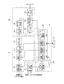
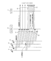
ところで、図3は、カメラサーバ16の画像圧縮符号化部41,ネットワーク処理部43および送信設定処理部44の要部構成について、上述の状態変化(イベント)検出の第1態様を実現するための構成に着目して示す図である。
The operation mode for preferentially transmitting the video imaged by the
[B-1-1] Description of First Mode Regarding Detection of State Change in Determination Unit FIG. 3 shows the main parts of the image
ここで、この図3に示すように、画像圧縮符号化部41は、静止画生成部41a,選択/合成部41b,DCT(Discrete Cosine Transform)・量子化部41cおよび符号化部41dをそなえ、NTSC(National Television Standards Committee)信号として入力された撮影装置11〜14からの映像情報について合成し圧縮符号化するようになっている。
Here, as shown in FIG. 3, the image
また、ネットワーク処理部43のネットワーク送信処理部43Aにおいては、データ分割部43a,RTP(Real-time Transport Protocol)・UTP(User Datagram Protocol)ヘッダ付与部43b,IPヘッダ付与部43c,優先情報付与部43dおよびMACヘッダ付与部43eをそなえ、画像圧縮符号化部41で圧縮符号化された映像情報についてIPパケット形式のデータに変換して、ルータ17を介してIPネットワーク30へ送出するようになっている。
Further, in the network
状態変化検出の第1態様を実現する送信設定処理部44は、各撮影装置11〜14近傍にそなえられた外部センサ15−1〜15−4からの検知信号をセンサ信号処理部45から受けて、この検知信号に基づいて、各撮影装置11〜14で撮影されている監視対象に状態変化が発生したか否かを判定するセンサ状態変化検出部44a−1をそなえている。
たとえば、外部センサ15−1〜15−4を監視対象としての一室(例えば、無人通信機械室等)に出入りするドアの開閉を検出するドア開閉センサにより構成された場合においては、送信設定処理部44のセンサ状態変化検出部44a−1においては、閉じている該当ドアが開けられた場合に状態変化有りと判定するようになっている。また、センサ15−1〜15−4を、人の接近などを感知するものとした場合には、このセンサ15−1〜15−4に人が接近した場合に状態変化有りと判定するようになっている。
The transmission
For example, in the case where the external sensor 15-1 to 15-4 is configured by a door opening / closing sensor that detects opening / closing of a door that enters and exits a room (for example, an unmanned communication machine room), the transmission setting process In the sensor state
図3に示す送信設定処理部44においては、上述のセンサ状態変化検出部44a−1とともに優先度設定部44fおよび終了制御部44gをそなえて構成されている。
センサ状態変化検出部44a−1において、上述のごとくいずれかの撮影装置11〜14についての監視対象の状態変化が有ったとする判定がなされた場合には、このセンサ状態変化検出部44a−1においては優先度設定部44fに対してその旨を通知するようになっている。これにより、優先度設定部44fにおいては、該当撮影装置11〜14で撮影された映像の優先送出のため、画像圧縮符号化部41およびネットワーク処理部43の設定処理を行なう。
The transmission
When it is determined in the sensor state
換言すれば、送信設定処理部44のセンサ状態変化検出部44a−1は、センサ信号処理部45と協働することによって、外部センサ15−1〜15−4からの検出情報をもとに、状態変化の発生有無を判定するセンサ情報判定部(図1の判定部16a)を構成する。又、画像圧縮符号化部41およびネットワーク処理部43は、送信設定処理部44の優先度設定部44fと協働することにより、優先送出部16b(図1参照)としての機能を実現している。
In other words, the sensor state
なお、優先度設定部44fは、画像圧縮符号化部41の静止画生成部41aの設定処理を行なう画質設定部44bと、選択/合成部41bの設定処理を行なう送信画像選択部44cと、DCT・量子化部41cの設定処理を行なう圧縮率設定部44dと、ネットワーク処理部43をなすネットワーク送信処理部43Aの優先情報付与部43dの設定処理を行なうネットワーク優先度設定部44eと、をそなえて構成されている。これらの各機能部における動作は、パケット優先送出の各態様についての説明の際に詳述する。
The
また、送信設定処理部44の終了制御部44gは、画像圧縮符号化部41およびネットワーク処理部43と優先度設定部44fが協働することにより行なわれる優先送出を終了させるもので、図1に示す終了制御部16cに相当するものである。この終了制御部44gにおける動作については、優先送出終了の各態様についての説明の際に詳述する。
〔B−1−2〕判定部における状態変化検出についての第2態様の説明
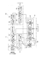
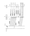
図4は、カメラサーバ16の画像圧縮符号化部41,ネットワーク処理部43および送信設定処理部44の要部構成について、上述の状態変化(イベント)検出の第2態様を実現するための構成に着目して示す図である。
The
[B-1-2] Description of Second Mode for Detection of State Change in Determination Unit FIG. 4 is a diagram illustrating a main configuration of the image
この図4に示すものにおいては、フレームメモリ42をそなえるとともに、画像圧縮符号化部41にフレーム間比較部41eがそなえられ、送信設定処理部44に画像状態変化検出部44a−2をそなえることにより、状態変化検出を行なっている点が異なっている。尚、図4中、図3と同一の符号は、ほぼ同様の部分を示している。
ここで、フレームメモリ42は、画像圧縮符号化部41の静止画生成部41aで順次生成される静止画像を格納するものであり、フレーム間比較部41eは、フレーム差分演算部として、静止画生成部41aで生成された静止画像とフレームメモリ42に格納されている直前の静止画像との差分を演算して、監視画像の直前のフレームと最新のフレーム間での比較を行なうものである。
4, the
Here, the
また、画像状態変化検出部44a−2は、前述の図3に示す送信設定処理部44のセンサ状態変化検出部44a−1に換えてそなえられたものであって、上述のフレーム間比較部41eで演算されたフレーム差分が、あらかじめ決められた閾値を超えるものであるか否かを判定するものである。そして、閾値を超えている場合には画像変化(状態変化)ありと判定して、その旨を優先度設定部44fに通知することができる。
Further, the image state
換言すれば、画像状態変化検出部44a−2は、フレーム間比較部41eからのフレーム差分の演算結果をもとに、状態変化の発生有無を判定するフレーム差分判定部としての機能を有している。
これにより、画像状態変化検出部44a−2において、上述のごとくいずれかの撮影装置11〜14についての監視対象の画像変化(状態変化)が有ったとする判定がなされた場合には、優先度設定部44fに対してその旨を通知する。そして、優先度設定部44fにおいては、該当撮影装置11〜14で撮影された映像の優先送出のため、画像圧縮符号化部41およびネットワーク処理部43の設定処理を行なうことができる。
In other words, the image state
Accordingly, when it is determined in the image state
〔B−1−3〕判定部における状態変化検出についての第3態様の説明
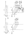
図5は、カメラサーバ16の画像圧縮符号化部41,ネットワーク処理部43および送信設定処理部44の要部構成について、上述の状態変化(イベント)検出の第3態様を実現するための構成に着目して示す図である。
この図5に示すものにおいては、前述の第1,第2態様にかかる構成(図3,図4参照)に比して、ネットワーク処理部43のネットワーク受信処理部43B,コマンド解析/処理部46および送信設定処理部44の実行状態変化検出部44a−3により、状態変化検出を実現する点が異なっている。尚、図5中、図3,図4と同一の符号は、ほぼ同様の部分を示している。
[B-1-3] Description of Third Mode Regarding State Change Detection in Determination Unit FIG. 5 is a diagram illustrating a main configuration of the image
5, the network
ここで、コマンド解析/処理部46は、ネットワーク受信処理部43Bを通じて監視局20から被監視局10に対するコマンド情報を入力されて、このコマンド内容について解析および処理を行なうものであるが、画像圧縮符号化部41およびネットワーク処理部43における送信設定の変化要求コマンド、特に特定の撮影装置11〜14にかかる映像情報を優先的に送出すべき指示を行なうコマンドである場合には、その旨を実行状態変化検出部44a−3に通知するようになっている。換言すれば、コマンド解析/処理部46は、監視局20から特定の撮影情報についての送信環境の設定を受け付ける送信環境設定受付部として機能する。
Here, the command analysis /
また、実行状態変化検出部44a−3は、前述の図3(図4)に示す送信設定処理部44のセンサ状態変化検出部44a−1(画像状態変化検出部44a−2)に換えてそなえられたものであって、コマンド解析/処理部46から上述のごとき指示を行なうコマンド受信の通知を受けた場合には、状態変化有りと判定して、その旨を優先度設定部44fに通知することができる。換言すれば、実行状態変化検出部44a−3は、コマンド解析/処理部46にて受け付けられた送信環境の設定をもとに、状態変化の発生有無を判定する優先要求判定部として機能する。
The execution state
これにより、実行状態変化検出部44a−3において、上述のごとくいずれかの撮影装置11〜14についての監視対象の画像送信環境の設定を変化させるコマンドが有ったとする判定(状態変化が有ったとする判定)がなされた場合には、優先度設定部44fに対してその旨を通知する。そして、優先度設定部44fにおいては、該当撮影装置11〜14で撮影された映像の優先送出のため、画像圧縮符号化部41およびネットワーク処理部43の設定処理を行なうことができる。
As a result, the execution state
〔B−2〕優先送出部によるパケット優先送出の態様の説明
送信設定処理部44において、上述の第1〜第3態様のごとく状態変化有りと判定された場合においては、図3〜図5に示す優先度設定部44fでは、その判定結果について通知されて、画質設定部44bにおいて優先的に送出すべき撮影装置11〜14の映像について解像度を上げる設定を行なうことができる。
[B-2] Description of Aspect of Packet Priority Transmission by Priority Transmission Unit When the transmission
まず、画像圧縮符号化部41の静止画生成部41aは、撮影装置11〜14からの各映像信号(NTSC信号)から、所定時間ごとの静止画フレームを生成するものであり、そのフレーム間隔や解像度については、優先度設定部44fの画質設定部44bで設定することができるようになっている。
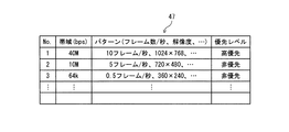
また、送信設定パターンメモリ47においては、静止画生成部41aにて生成される静止画フレームについての生成パターンを、例えば図6に示すように複数種類記憶するようになっている。そして、この送信設定パターンメモリ47では、この図6に示すように、優先度に応じて送信フレームの解像度のパターンを設定しておくことができる。
First, the still
Further, in the transmission
ここで、状態変化を検出した映像情報を優先的にネットワーク30へ送出するため、静止画生成部41aにおいては、生成される静止画の画質(単位時間当たりに生成するフレーム数や解像度等)を切り替えることができるようになっている。
具体的には、優先度設定部44fの画質設定部44bにおいては、高い優先度で映像情報を送出しようとする場合には、この送信設定パターンメモリ47から、対応する高優先レベルの解像度設定情報(例えば図6に示すNo1のパターンファイルの情報)を取り出し、取り出した解像度設定情報をもとに、静止画生成部41aで生成される静止画フレームの画質設定の設定処理を行なうことができるのである。この場合においては、高優先のパターンとしては、単位時間当たりのフレーム数,解像度ともに高画質となるようにしている。
Here, in order to preferentially send the video information whose state change has been detected to the
Specifically, in the image
したがって、上述の静止画生成部41a,画質設定部44bおよび送信設定パターンメモリ47が協働することによって、いずれかのセンサ状態変化検出部44a−1,画像状態変化検出部44a−2,実行状態変化検出部44a−3(以下においては、これらを総称して状態変化検出部と記載する場合がある)にて状態変化の発生有りと判定された監視対象についての撮影情報を、画質を高めて送出する画質制御送出部を構成する。
Accordingly, the above-described still
また、画像圧縮符号化部41の選択/合成部41bは、静止画生成部41aで生成された各撮影装置11〜14からの各静止画フレームのうち、必要な静止画フレームを選択してから1つの静止画フレームに合成し、所定時間ごとに出力するものである。この選択/合成部41bにおけるフレーム合成に必要な静止画フレームの選択については、送信画像選択部44cで選択設定されるようになっている。
In addition, the selection /
すなわち、送信画像選択部44cにおいては、状態変化を検出した映像情報を優先的にネットワーク30へ送出するため、状態変化にかかる映像情報のみを送出できるように、撮影装置11〜14で撮影された映像情報のうちで、IPネットワーク30へ送出すべき映像情報について選別することができるようになっている。
〔B−2−1〕 具体的には、状態変化検出部44a−1〜44a−3で状態変化を検出していない状態においては、静止画生成部41aで生成された静止画フレームのうちで、全ての撮影装置11〜14からのものを合成する一方、状態変化検出部44a−1〜44a−3で状態変化を検出した場合においては、状態変化を検出した撮影装置11〜14からの静止画フレームのみを選択してDCT・量子化部41cに出力するようになっている。これにより、状態変化に該当する画像以外のカメラ映像の送出を止め、状態変化を検出した画像のみをIPネットワーク30に送出することができる。
That is, in the transmission
[B-2-1] Specifically, in a state in which no state change is detected by the state
たとえば、図7の信号シーケンス図に示すように、状態変化の発生していない通常時においては、撮影装置11〜14からの映像情報C1については、全ての画像が合成されて、ネットワーク処理部43を通じてIPパケットP1としてIPネットワーク30に送出されているが、撮影装置13についての状態変化がいずれかの状態変化検出部44a−1〜44a−3で検出されると、撮影装置13からの映像情報C2のみから静止画フレームを生成し、IPパケットP2としてIPネットワーク30に送出する。このとき、撮影装置13以外の撮影装置11,12,14からの映像の送信については停止させる。
For example, as shown in the signal sequence diagram of FIG. 7, in the normal time when no state change has occurred, all the images are synthesized for the video information C1 from the
したがって、上述の送信画像選択部44cおよび選択/合成部41bにより、状態変化検出部44a−1〜44a−3にて状態変化の発生無しと判定された監視対象についての撮影情報の送出を停止させるとともに、状態変化検出部44a−1〜44a−3にて状態変化の発生有りと判定された監視対象についての撮影情報を送出する撮影情報選択送出部を構成する。
Therefore, the transmission
さらに、DCT・量子化部41cは、選択/合成部41bから所定時間ごとに出力されてくる静止画フレームについて、離散コサイン変換処理および量子化処理(圧縮処理)を行なって、符号化部41dに出力するものであるが、優先度設定部44fの圧縮率設定部44dは、このDCT・量子化部41cでの圧縮処理による圧縮率についても設定することができるようになっている。
Further, the DCT /
〔B−2−2〕 また、状態変化を検出した映像情報を優先的にネットワークへ送出するために、ネットワーク送信処理部43Aの優先情報付与部43dは、IPヘッダ付与部43cでIPヘッダが付与された送信前パケットについて、RSVP-TE(Resource Reservation Protocol Traffic Engineering;RFC3209)のためのMPLS(MultiProtocol Label Switching)ラベルを優先情報として付与することができるようになっている。このMPLSラベルが付与されたIPパケットは、IPネットワーク30上の定められたルートを辿って帯域が確保されるようになっている。
[B-2-2] Further, in order to preferentially send the video information whose state change has been detected to the network, the priority
優先度設定部44fのネットワーク優先度設定部44eは、上述の優先情報付与部43dの設定処理を行なうもので、この設定処理を通じて、IPネットワーク30上の定められたルートにおいて帯域確保を要求するラベルを、IPヘッダ付与部43cからのパケットに追加して付与させることができるようになっている。
これにより、MPLSネットワークの入口となるルータ17では、この帯域確保を要求するラベルが付与されたパケットを受け取って、対応する帯域確保のための処理を行なう。そして、帯域確保がなされた場合には、帯域確保が完了した旨の回答をカメラサーバ16に通知する。カメラサーバ16では、ネットワーク受信処理部43Bにおいてルータ17からの帯域確保完了の回答を受けると、ネットワーク優先度設定部44eによるラベル設定処理によって、帯域確保されたルートを通じて映像情報を確実に監視局20へ伝送することができる。
The network
As a result, the
たとえば、図8の信号シーケンス図に示すように、状態変化の発生していない通常時においては、撮影装置11〜14からの映像情報C3については、ネットワーク処理部43を通じてIPパケットP3としてIPネットワーク30に送出されている。このとき、撮影装置13についての状態変化をいずれかの状態変化検出部44a−1〜44a−3(図8中においては外部センサ15−1〜15−4からの信号をもとに状態変化を検出するセンサ状態変化検出部44a−1)で検出すると、ネットワーク優先度設定部44eでは優先情報付与部43cを制御することにより、ルータ17を通じてIPネットワーク30に伝送されるIPパケットに帯域確保を要求するMPLSラベルを付与する(図8のP4参照)。
For example, as shown in the signal sequence diagram of FIG. 8, in a normal time when no state change occurs, the video information C3 from the
ルータ17では、上述の帯域確保要求に対して帯域確保のための処理を行なって、帯域確保がなされるとその旨をカメラサーバ16に対して回答する(図8のP5参照)。ルータ17からの帯域確保完了の回答を受けると、優先情報付与部43dでは、帯域確保されたルートで転送されるパケットであることを示すラベルを優先情報として付与することにより、カメラサーバ16からのIPパケットP6はIPネットワーク30において帯域確保されたルートを辿って転送される。
The
したがって、上述のネットワーク優先度設定部44eおよび優先情報付与部43dにより、状態変化検出部44a−1〜44a−3にて状態変化の発生有りと判定された監視対象についての撮影情報を送出するためのネットワーク30の帯域を確保する制御を行なう帯域確保制御部を構成する。
〔B−2−3〕 また、状態変化を検出した映像情報を優先的にネットワーク30へ送出するために、ネットワーク送信処理部43Aの優先情報付与部43dは、変形例として、IPヘッダ付与部43cでIPヘッダが付与された送信前パケットについて、優先情報ビットを付与するようにしてもよい。
Therefore, in order to send out the photographing information about the monitoring target determined by the state
[B-2-3] Further, in order to preferentially send the video information whose state change has been detected to the
具体的には、優先情報付与部43dにおいては、ネットワーク優先度設定部44eからの制御を受けて、Virtual LAN Tag priorityフィールドや、ToS(Type of Service)フィールドに優先ビットを付与するものがある。
なお、Virtual LAN Tag priorityとは、IEEE(Institute of Electrical and Electronic Engineers )802.1QのVLAN(仮想LAN)タグヘッダに含まれる、3ビットのユーザープライオリティー(優先度記述)フィールドであって、IEEE802.1pにて標準化されているものである。また、Type of Serviceとは、パケット優先度を記述するIPヘッダー内の8ビット長のフィールドをいうものである。
Specifically, in the priority
The Virtual LAN Tag priority is a 3-bit user priority (priority description) field included in the VLAN (Virtual LAN) tag header of IEEE (Institute of Electrical and Electronic Engineers) 802.1Q. Is standardized. “Type of Service” refers to an 8-bit length field in the IP header describing packet priority.
たとえば、状態変化の発生していない通常時においては、図9(a)の信号シーケンス図に示すように、撮影装置11〜14からの映像情報C4については、画像圧縮符号化部41およびネットワーク処理部43を通じてIPパケットP7としてIPネットワーク30に送出されている。このとき、優先情報付与部43cでIPパケットP7に付与する優先情報ビットの内容は「非優先」である旨を示すものとする。
For example, in a normal time when no state change occurs, as shown in the signal sequence diagram of FIG. 9A, the video information C4 from the
そして、図9(b)の信号シーケンス図に示すように、撮影装置13についての状態変化(イベント)Eをいずれかの状態変化検出部44a−1〜44a−3(図9(b)中においてはセンサ状態変化検出部44a−1)で検出すると、優先度設定部44fのネットワーク優先度設定部44eでは優先情報付与部43cを制御することにより、ルータ17を通じてIPネットワーク30に伝送されるIPパケットP8に付与する優先情報ビットの内容を、「高優先」とする。
Then, as shown in the signal sequence diagram of FIG. 9B, the state change (event) E of the photographing
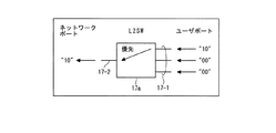
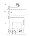
ルータ17においては、図10に示すように、カメラサーバ16からのIPパケットについて、上述のごとき優先情報ビットの内容に応じてスイッチングするためのL2(Layer-2)スイッチ17aをそなえることができる。L2スイッチ17aは、この図10に示すように、複数のユーザポート17−1から入力される(カメラサーバ16側から入力される)IPパケットのうちで、高優先のToSビット値が付与されたIPパケットを優先的にネットワークポート17−2へ(IPネットワーク30側へ)出力するものである。
As shown in FIG. 10, the
たとえば、優先制御ビットとしての2ビットのToS値として、“00”を「非優先」のビット値とし、“10”を「高優先」のビット値とすると、ルータ17のL2スイッチ17aにおいては、ユーザポート17−1から入力される複数のIPパケットのうちで、「高優先」のビットである“10”のToSビットが付されたIPパケットを、優先的にネットワークポート17−2へ出力する。
For example, as a 2-bit ToS value as a priority control bit, when “00” is a bit value of “non-priority” and “10” is a bit value of “high priority”, in the
これにより、例えば、図11に示すように、監視局20が、帯域100Mbps程度のIPネットワーク30を介して2つの被監視局10−1,10−2を収容する場合において、双方の被監視局10−1,10−2ともに状態変化の発生していない通常時においては、各被監視局10−1,10−2のカメラサーバ16では、撮影装置11〜14からの映像情報を合成し、「非優先」のToSビットが付与されたIPパケットとして伝送する。
Accordingly, for example, as shown in FIG. 11, when the
このとき、図12の信号シーケンス図に示すように、各被監視局10−1,10−2のカメラサーバ16では、ともに自身で収容する撮影装置11〜14からの10Mbpsの映像情報を合成して、合計40Mbpsの映像情報P1,P2としてそれぞれ送信している。従って、IPネットワーク30においては、トータルで80Mbpsの帯域を使用して映像情報のIPパケットを転送する。
At this time, as shown in the signal sequence diagram of FIG. 12, the
そして、被監視局10−2のカメラサーバ16において、自身の収容する撮影装置11〜14での監視対象について状態変化(イベント)Eを検出した場合においては、被監視局10−1からの映像については、「非優先」のToSビットが付与されたIPパケットとして伝送するが、状態変化が検出された被監視局10−2からの映像については、「高優先」のToSビットが付与されたIPパケットとして伝送する。
When the
このとき、優先度設定部44fの画質設定部44bによる静止画生成部41aの設定により(図3〜図5参照)、状態変化が検出された一つの撮影装置11〜14(例えば撮影装置13)からの映像情報について、帯域を10Mbpsから40Mbpsにして、画質を高めるようにすることができる。
この場合においては、被監視局10−2からの「高優先」のToSビットが付与されたIPパケットは、70Mbpsの帯域を使用することになる。従って、IPネットワーク30においては、トータルで110Mbpsの帯域を使用して映像情報のIPパケットを転送することになり、IPネットワーク30の帯域(100Mbps)を超えることになる。
At this time, one
In this case, the IP packet provided with the “high priority” ToS bit from the monitored station 10-2 uses a bandwidth of 70 Mbps. Therefore, in the
このとき、被監視局10−1から映像情報は、「非優先」のToSビットが付与されたIPパケットとして伝送されるので、IPネットワーク30の帯域を越える部分については、パケット廃棄が生ずることも考えられるが、被監視局10−2から映像情報は、「高優先」のToSビットが付与されたIPパケットとして伝送されるので、ルータ17のL2スイッチ17aによるスイッチングを通じて、確実にパケット転送することができる。
At this time, since the video information is transmitted from the monitored station 10-1 as an IP packet to which the “non-priority” ToS bit is added, packet discard may occur in a portion exceeding the bandwidth of the
すなわち、パケット廃棄が生じた「非優先」パケットについてのディスプレイ表示には、遅延が生じたり情報の欠落等が生じたりすることが考えられるが、「高優先」パケットについてのディスプレイ表示が「非優先」パケットのディスプレイ表示よりも重要であるため、上述のごとき遅延や欠落等は無視することができる。
したがって、上述のネットワーク優先度設定部44eと優先情報付与部43dとが協働することにより、状態変化検出部44a−1〜44a−3にて状態変化の発生有りと判定された監視対象についての撮影情報から、優先処理情報が付与されたパケットを生成する優先パケット生成部を構成する。
In other words, there may be a delay or loss of information in the display for “non-priority” packets that have been discarded, but the display for “high priority” packets is “non-priority”. Since it is more important than the display of the packet, delays and omissions as described above can be ignored.
Therefore, the above-described network
〔B−3〕監視局によるディスプレイ表示態様の説明
上述のごとく、画像圧縮符号化部41およびネットワーク処理部43において、優先送出部16bとしての送出処理がなされたIPパケットは、IPネットワーク30を通じてパケット転送されて、監視局20にて受信されることになる。
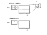
監視局20の端末装置21においては、状態変化を検出していない通常時においては、例えば図13(a)に示すように、被監視局10からの映像情報について、複数画面を分割してディスプレイ21a上に表示しておき、各撮影装置11〜14からの映像情報を均等に表示(A〜Dの4画面表示)することができる。
[B-3] Description of Display Display Mode by Surveillance Station As described above, the IP packet subjected to the sending process as the
In the
また、被監視局10のいずれかの撮影装置11〜14について状態変化を検出した場合においては、被監視局10では、この状態変化検出にかかる撮影装置11〜14からの映像情報について優先送出している。監視局20においては、カメラサーバ16から優先送出された映像情報について拡大してディスプレイ21a上に表示する。被監視局20の撮影装置11〜14のうちで、いずれか一つの撮影装置11〜14において状態変化を検出した場合には、例えば図13(b)に示すように、当該撮影装置11〜14からの映像情報のみを画面全体を占めた表示(1画面表示)で拡大表示する。
Further, when a change in state is detected for any of the
換言すれば、監視局における端末装置21は、図1に示すように、カメラサーバ16から優先的に送出された、判定部16aにて状態変化の発生有りと判定された監視対象についての撮影情報について受信すると、当該撮影情報をクローズアップして表示すべく制御するクローズアップ表示制御部としての機能を有している。
〔B−4〕終了制御部によるパケット優先送出終了の態様の説明
上述のごとく、状態変化の検出時においては、カメラサーバ16では、優先送出部16b(図1参照)により、かかる映像情報を優先送出することができるが、その後、終了制御部16c(図1参照、図3〜図5において符号44g参照)では、以下に示す2つの態様により、かかる映像情報の優先送出を終了させることができる。
In other words, as shown in FIG. 1, the
[B-4] Description of Mode of Ending Packet Preferential Sending by End Control Unit As described above, when detecting a state change, the
〔B−4−1〕終了制御部によるパケット優先送出終了の第1態様の説明
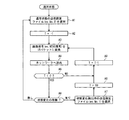
図14は、終了制御部44g(図3〜図5参照)によるパケット優先送出終了の第1態様を説明するためのフローチャートである。即ち、この図14に示すように、終了制御部44gでは、あらかじめ設定した一定時間経過後(例えば5分後、図14中においてはT=60としたTがT<0となるまでの時間経過後)に自動的に送信設定を通常状態に戻すことができる。
[B-4-1] Description of First Mode of Ending Packet Preferential Transmission by End Control Unit FIG. 14 is a diagram for explaining a first mode of end of packet preferential transmission by the
すなわち、通常状態においては、優先度設定部44f(図3〜図5参照)では、送信設定パターンメモリ47から通常状態の送信設定ファイル(例えばNo2の設定ファイル)を取り出すとともに(ステップA1)、状態変化後の優先送出時間を計時するための変数Tの初期値をT=−1として(ステップA2)、撮影装置11〜14からの映像信号(NTSC信号)について、画像符号化圧縮部41,ネットワーク処理部43での処理を通じてIPパケットに変換して(ステップA3)、IPネットワーク30へ送出する(ステップA4)。
That is, in the normal state, the
そして、このような通常状態での伝送中において(ステップA1〜A4,ステップA5のYESルート,ステップA6の「無し」ルートによるループ)、いずれかの撮影装置11〜14においての監視対象につき状態変化が生じた場合においては(ステップA6の「有り」ルート)、優先度設定部44fでは、送信設定パターンメモリ47から状態変化検出時の送信設定ファイル(例えばNo1の設定ファイル)を取り出して、このファイルに従って画像圧縮符号化部41やネットワーク処理部43における送信設定について設定処理を行なう(ステップA7)。
During transmission in such a normal state (step A1 to A4, YES route in step A5, loop due to “none” route in step A6), the state change of the monitoring target in any of the
このように送信設定処理がなされた画像圧縮符号化部41およびネットワーク処理部43においては、入力される映像信号を、優先送出用にIPパケット化してIPネットワーク30へ送出する。このとき、終了制御部44gにおいては、上述の変数TをT=「60」とした上で、このTを「1」ずつ減らしてゆくことで計時を行なう(ステップA8〜ステップA9,ステップA3,ステップA4)。
In the image
その後、画像圧縮符号化部41およびネットワーク処理部43においては、優先送出部16bとして状態変化検出時の優先送出を、終了制御部44gにおいて管理する変数TがT<0となるまで継続する(ステップA5のNOルート,ステップA9,ステップA3,ステップA4によるループ)。
そして、終了制御部44gにおいては、管理している変数TがT<0となった場合に、上述の優先送出を終了させることができるが、このとき、更に、判定部16aとしての状態変化検出部44a−1〜44a−3において状態変化が解消されていることを判断した上で優先送出を終了させることもできる。
Thereafter, in the image
In the
具体的には、判定部16aとしての状態変化検出部44a−1〜44a−3において状態変化が解消されている場合には、その時点で優先送出部16bによる優先送出動作を、通常の映像情報送出動作に戻す(ステップA5のYESルート,ステップA6の「無し」ルート)。
なお、状態変化が解消されていないと判定された場合には(例えば、外部センサ15−3においてドアが開状態のままである場合等)、終了制御部16cでは、状態変化が解消されるまで、再びTの値を「60」として計時を行ないながら、優先送出部16bにおける優先送出を継続する(ステップA6の「有り」ルート)。
Specifically, when the state change is eliminated in the state
When it is determined that the state change has not been eliminated (for example, when the door remains open in the external sensor 15-3), the
なお、センサ状態変化検出部44a−1(図3参照)においては、状態変化を検出した外部センサ15−1〜15−4から、状態変化を知らせる信号入力が無くなった場合に、状態変化が解消したことを識別する。又、画像状態変化検出部44a−2(図4参照)においては、フレーム間の差分を認識し状態変化を検出していた画像において、あらかじめ設定した閾値より小さい差分しか検出されなくなった場合に、状態変化が解消したことを識別する。更に、実行状態変化検出部44a−3(図5参照)においては、監視局20からの要求による送信設定の変化要求解除コマンドを受け取った場合に、状態変化が解消したことを識別する。
In the sensor state
したがって、第1態様にかかる終了制御を行なう終了制御部44g(16c)は、優先送出部16bにて優先送出が行われている時間を計時する計時部としての機能と、計時部にて優先送出が行なわれている時間が所定時間経過した場合に、優先送出部での前記優先送出を終了させる第1制御部としての機能を有している。
〔B−4−2〕終了制御部によるパケット優先送出終了の第2態様の説明
図15は、終了制御部44g(図3〜図5参照)によるパケット優先送出終了の第2態様を説明するためのフローチャートである。即ち、この図15に示すように、終了制御部44gでは、判定部16aとしての状態変化検出部44a−1〜44a−3において、上述の第1態様の場合と同様に状態変化が解消したことを識別して、自動的に送信設定を通常状態に戻すようにしている。
Accordingly, the
[B-4-2] Description of second mode of end of packet priority transmission by end control unit FIG. 15 is a diagram for describing a second mode of end of priority packet transmission by the
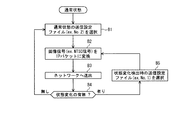
すなわち、通常状態においては、優先度設定部44f(図3〜図5参照)では、送信設定パターンメモリ47から通常状態の送信設定ファイル(例えばNo2の設定ファイル)を取り出すとともに(ステップB1)、撮影装置11〜14からの映像信号(NTSC信号)について、画像符号化圧縮部41,ネットワーク処理部43での処理を通じてIPパケットに変換して(ステップB2)、IPネットワーク30へ送出する(ステップB3)。
That is, in the normal state, the
そして、このような通常状態での伝送中において(ステップB1〜B3,ステップB4の「無し」ルートによるループ)、いずれかの撮影装置11〜14においての監視対象につき状態変化が生じた場合においては(ステップB4の「有り」ルート)、優先度設定部44fでは、送信設定パターンメモリ47から状態変化検出時の送信設定ファイル(例えばNo1の設定ファイル)を取り出して、このファイルに従って画像圧縮符号化部41やネットワーク処理部43における送信設定について設定処理を行なう(ステップB5)。
And, in such a normal state transmission (loop by “None” route in Steps B1 to B3 and Step B4), when a state change occurs in the monitoring target in any of the photographing
このように送信設定処理がなされた画像圧縮符号化部41およびネットワーク処理部43においては、入力される映像信号を、優先送出用にIPパケット化してIPネットワーク30へ送出する(ステップB2,ステップB3)。
その後、判定部16aとしての状態変化検出部44a−1〜44a−3において状態変化が解消されていることを判断した上で優先送出を終了させる。具体的には、判定部16aとしての状態変化検出部44a−1〜44a−3において状態変化が解消されている場合には、その時点で優先送出部16bによる優先送出動作を、通常の映像情報送出動作に戻す(ステップB4の「無し」ルートからステップB1)。
In the image
After that, the
なお、状態変化が解消されていないと判定された場合には(例えば、外部センサ15−3においてドアが開状態のままである場合等)、終了制御部16cでは、状態変化が解消されるまで、優先送出部16bにおける優先送出を継続する(ステップB4の「有り」ルート)。
したがって、判定部16aとしての状態変化検出部44a−1〜44a−3は、状態変化の発生有りと判定された監視対象について、状態変化の発生が無くなったか否かを判定する状態復旧判定部としての機能を有している。更に、第2態様にかかる終了制御を行なう終了制御部44g(16c)は、状態変化検出部44a−1〜44a−3において、状態変化の発生有りと判定された監視対象について、状態変化の発生が無くなったと判定された場合に、画像圧縮符号化部41およびネットワーク処理部43での優先送出を終了させる第2制御部としての機能を有している。
When it is determined that the state change has not been eliminated (for example, when the door remains open in the external sensor 15-3), the
Therefore, the state
〔C〕本実施形態にかかる撮影情報送信システムについての作用効果の説明
このように、本実施形態によれば、カメラサーバ16が、優先送出部16bにより、判定部16aで状態変化の発生有りと判定された監視対象についての撮影情報を、状態変化の発生無しと判定された監視対象についての撮影情報に優先して、監視局20へ送出することができるので、監視対象についてのリアルタイム(実時間)での遠隔監視を実現しつつ、状態変化の発生ありとされた重要な監視対象についての撮影情報を、ネットワーク帯域の有効利用を図りながら、確実に送出することができる利点がある。
[C] Description of the operation and effect of the photographing information transmission system according to the present embodiment As described above, according to the present embodiment, the
また、優先送出部16bを、画質を高めて送出するように構成することができるので、状態変化の発生ありとされた重要な監視対象についての撮影情報についてのディスプレイ表示をより鮮明にすることができるので、監視局20においては、より正確な監視を行なうことができる利点がある。
さらに、撮影情報選択制御部としての送信画像選択部44cおよび選択/合成部41bにより、状態変化の発生ありとされた重要な監視対象からのみ送信すべき映像フレームを構成することができるので、監視の際には重要な映像のみを、帯域を効率的に使用して伝送することができ、ネットワークコストの効率化を図ることができる利点がある。
In addition, since the
Furthermore, since the transmission
また、上述の状態変化の発生ありとされた監視対象についての画質を高める機能と、撮影情報選択制御部としての機能とを組み合わせることにより、あらかじめ状態変化が発生した際の最大帯域を持ったネットワークを用意しておく場合と比較して、帯域使用の効率性を飛躍的に向上させることができる。
さらに、優先パケット生成部または帯域確保制御部としてのネットワーク優先度設定部44eおよび優先情報付与部43dにより、他のカメラサーバ16で使用する帯域について考慮することなく、ネットワーク帯域の有効利用を図りながら、状態変化の発生ありとされた重要な監視対象についての送出を確実なものとすることができる。
In addition, a network having the maximum bandwidth when a state change has occurred in advance by combining the above-described function for enhancing the image quality of a monitoring target that is considered to have undergone a state change and the function as a photographing information selection control unit. As compared with the case of preparing the network, it is possible to dramatically improve the band use efficiency.
Further, the network
すなわち、ある画像にイベントが発生した場合、他のカメラサーバ16からの画像の伝送レートを落とす、または情報伝送を止めるようにする態様を想定した場合、ある画像にイベントが発生すると、イベントを検出したカメラサーバは自分に接続されているカメラの映像を制御(伝送レートを落とす、または止める)すると同時に、他のカメラサーバに対し、イベントの検出を通知する必要がある。このため、カメラサーバ間または監視局との制御信号の手順が必要となる。カメラサーバの台数が多くなれば、この制御信号が多くの帯域を使うこととなる。
That is, when an event occurs in a certain image, assuming that the transmission rate of the image from another
これに対し、本実施形態によれば、他のカメラサーバで使用する帯域を考慮する必要なく、イベントを検出した画像の伝送パケットを制御するだけで、カメラサーバ間の信号のやり取りは不要である。このため、上述のごとく想定した態様に比較すれば、本実施形態においては、ネットワークの負荷および処理の手順への影響を少なくさせることができる。 On the other hand, according to the present embodiment, it is not necessary to consider the bandwidth used by other camera servers, and it is only necessary to control the transmission packet of the image that detected the event, and there is no need to exchange signals between the camera servers. . For this reason, compared with the aspect assumed as mentioned above, in this embodiment, the influence on the load of a network and the procedure of a process can be decreased.
〔D〕その他
上述した実施形態にかかわらず、本発明の趣旨を逸脱しない範囲で種々変形して実施することもできる。
たとえば、上述の本実施形態においては、カメラサーバ16においては、静止画フレームを順次送信するようになっているが、本発明によればこれに限定されるものではなく、例えば、撮影装置11〜14で撮影された映像情報としての動画像情報を合成して、例えばMPEG(Moving Picture Experts Group)等の方式で圧縮符号化することにより得られる映像情報を送信するように構成することもできる。この場合において、上述の判定部16における状態変化検出の第2態様を実現するにあたっては、DCT・量子化部41cからの情報をもとにフレーム間差分を演算し、得られた演算結果をもとに状態変化の有無を判定することができる。
[D] Others Regardless of the embodiment described above, various modifications can be made without departing from the spirit of the present invention.
For example, in the above-described embodiment, the
また、上述の各実施形態においては、送信設定処理部44の優先度設定部44fにおいては、画質設定部44b,送信画像選択部44c,圧縮率設定部44dおよびネットワーク優先度設定部44eをそなえているが、本発明によれば、送信画像選択部44c,圧縮率設定部44dおよびネットワーク優先度設定部44eのいずれか一つを設けて設定処理を行なうことで、少なくとも状態変化が検出された撮影装置11〜14にかかる映像についての送信を確実なものとすることができる。尚、これらの設定を適宜組み合わせることで、状態変化が検出された撮影装置にかかる映像の通信に対する信頼性が向上し、又画質設定部44bにおける設定処理と組み合わせることで、信頼度のみならず画像品質も向上することはいうまでもない。
In each of the above-described embodiments, the
また、上述の実施形態により、本発明の装置を製造することは可能である。
〔E〕付記
(付記1) 監視対象についての撮影情報を複数種類取り込み、前記取り込んだ撮影情報を、ネットワークを介して監視局へ送出する撮影情報サーバであって、
前記複数種類の撮影情報にかかる監視対象についての状態変化の発生有無をそれぞれ判定する判定部と、
該判定部にて前記状態変化の発生有りと判定された監視対象についての撮影情報を、前記状態変化の発生無しと判定された監視対象についての撮影情報に優先して、前記監視局へ送出する優先送出部と、をそなえて構成されたことを特徴とする、撮影情報サーバ。
Further, the device of the present invention can be manufactured according to the above-described embodiment.
[E] Supplementary Note (Supplementary Note 1) A photographing information server that captures a plurality of types of photographing information about a monitoring target and sends the captured photographing information to a monitoring station via a network,
A determination unit that determines whether or not a state change has occurred with respect to the monitoring target according to the plurality of types of imaging information;
Shooting information about the monitoring target determined to have the occurrence of the state change by the determination unit is sent to the monitoring station in preference to shooting information about the monitoring target determined to have no occurrence of the state change. An imaging information server comprising a priority transmission unit.
(付記2) 各監視対象の状態変化を検出する外部センサがそなえられ、
該判定部が、該外部センサからの検出情報をもとに、前記状態変化の発生有無を判定するセンサ情報判定部をそなえて構成されたことを特徴とする、付記1記載の撮影情報サーバ。
(付記3) 該判定部が、
前記複数の監視対象ごとに取り込まれた撮影情報のフレーム差分を演算するフレーム差分演算部と、
該フレーム差分演算部における前記フレーム差分の演算結果をもとに、前記状態変化の発生有無を判定するフレーム差分判定部と、をそなえて構成されたことを特徴とする、付記1記載の撮影情報サーバ。
(Appendix 2) There is an external sensor that detects the status change of each monitoring target.
The imaging information server according to
(Supplementary note 3)
A frame difference calculation unit that calculates a frame difference of imaging information captured for each of the plurality of monitoring targets;
The imaging information according to
(付記4) 該判定部が、
前記監視局から特定の撮影情報についての送信環境の設定を受け付ける送信環境設定受付部と、
該送信環境設定受付部にて受け付けられた前記送信環境の設定をもとに、前記状態変化の発生有無を判定する優先要求判定部と、をそなえて構成されたことを特徴とする、付記1記載の撮影情報サーバ。
(Supplementary note 4)
A transmission environment setting reception unit for receiving a transmission environment setting for specific shooting information from the monitoring station;
(付記5) 該優先送出部が、
該判定部にて前記状態変化の発生有りと判定された監視対象についての撮影情報について、画質を高めて送出する画質制御送出部をそなえて構成されたことを特徴とする、付記1〜4のいずれか1項記載の撮影情報サーバ。
(付記6) 該優先送出部が、
該判定部にて前記状態変化の発生有りと判定された監視対象についての撮影情報から、優先処理情報が付与されたパケットを生成する優先パケット生成部をそなえて構成されたことを特徴とする、付記1〜5のいずれか1項記載の撮影情報サーバ。
(Supplementary note 5)
Appendices 1-4 characterized by comprising an image quality control sending unit that sends out the image quality of the monitored information that has been judged to be subject to the occurrence of the state change by the judging unit. The imaging information server according to any one of the preceding claims.
(Appendix 6) The priority sending unit
It is characterized by comprising a priority packet generation unit that generates a packet to which priority processing information is given from shooting information about a monitoring target that is determined to have the occurrence of the state change by the determination unit. The imaging information server according to any one of
(付記7) 該優先送出部が、
該判定部にて前記状態変化の発生有りと判定された監視対象についての撮影情報を送出するための前記ネットワークの帯域を確保する制御を行なう帯域確保制御部をそなえて構成されたことを特徴とする、付記1〜5のいずれか1項記載の撮影情報サーバ。
(付記8) 該優先送出部が、該判定部にて前記状態変化の発生無しと判定された監視対象についての撮影情報の送出を停止させるとともに、該判定部にて前記状態変化の発生有りと判定された監視対象についての撮影情報を送出する撮影情報選択送出部をそなえて構成されたことを特徴とする、付記1〜5記載の撮影情報サーバ。
(Supplementary note 7)
It is characterized by comprising a bandwidth securing control unit that performs control for securing the bandwidth of the network for sending imaging information about the monitoring target that is determined by the determining unit to have the occurrence of the state change. The imaging information server according to any one of
(Supplementary Note 8) The priority transmission unit stops transmission of imaging information for a monitoring target determined by the determination unit as having no occurrence of the state change, and the determination unit determines that the state change has occurred. The imaging information server according to any one of
(付記9)該優先送出部における前記優先送出を終了させる終了制御部をそなえて構成されたことを特徴とする、付記1〜8のいずれか1項記載の撮影情報サーバ。
(付記10) 該終了制御部が、
該優先送出部にて前記優先送出が行われている時間を計時する計時部と、
該計時部にて前記優先送出が行なわれている時間が所定時間経過した場合に、該優先送出部での前記優先送出を終了させる第1制御部と、をそなえて構成されたことを特徴とする、付記9記載の撮影情報サーバ。
(Supplementary note 9) The photographing information server according to any one of
(Supplementary Note 10) The termination control unit
A time counting unit for measuring the time during which the priority transmission is performed in the priority transmission unit;
A first control unit configured to terminate the priority transmission in the priority transmission unit when a predetermined time has elapsed in the timed transmission unit in the time measuring unit. The shooting information server according to appendix 9.
(付記11) 該終了制御部が、
該判定部において前記状態変化の発生有りと判定された監視対象について、状態変化の発生が無くなったか否かを判定する状態復旧判定部をそなえ、
該状態復旧判定部において、前記状態変化の発生有りと判定された監視対象について、状態変化の発生が無くなったと判定された場合に、該優先送出部での前記優先送出を終了させる第2制御部と、をそなえて構成されたことを特徴とする、付記9記載の撮影情報サーバ。
(Supplementary Note 11) The termination control unit
For the monitoring target determined to have the occurrence of the state change in the determination unit, the state recovery determination unit for determining whether or not the state change has occurred,
A second control unit that terminates the priority transmission in the priority transmission unit when it is determined in the state recovery determination unit that the state change has not occurred for the monitoring target that has been determined to have undergone the state change; The imaging information server according to appendix 9, characterized by comprising:
(付記12) 監視対象についての映像を撮影する複数の撮影装置と、
該撮影装置にて撮影された映像を監視用に受信する監視局と、
各撮影装置にて撮影された撮影情報を取り込み、前記取り込んだ撮影情報を、ネットワークを介して該監視局へ送出する撮影情報サーバとをそなえ、
該撮影情報サーバが、
各撮影装置にて撮影された撮影情報にかかる監視対象についての状態変化の発生有無をそれぞれ判定する判定部と、
該判定部にて前記状態変化の発生有りと判定された監視対象についての撮影情報を、前記状態変化の発生無しと判定された監視対象についての撮影情報に優先して、前記監視局へ送出する優先送出部と、をそなえて構成されたことを特徴とする、撮影情報送信システム。
(Supplementary note 12) a plurality of photographing devices for photographing a video about a monitoring target;
A monitoring station for receiving the video imaged by the imaging device for monitoring;
A photographing information server that captures photographing information photographed by each photographing device and sends the captured photographing information to the monitoring station via a network,
The imaging information server
A determination unit that determines whether or not a state change has occurred with respect to a monitoring target according to imaging information captured by each imaging device; and
Shooting information about the monitoring target determined to have the occurrence of the state change by the determination unit is sent to the monitoring station in preference to shooting information about the monitoring target determined to have no occurrence of the state change. An imaging information transmission system comprising a priority transmission unit.
(付記13) 該監視局が、該撮影情報サーバから優先的に送出された、該判定部にて前記状態変化の発生有りと判定された監視対象についての撮影情報について受信すると、当該撮影情報をクローズアップして表示すべく制御するクローズアップ表示制御部をそなえて構成されたことを特徴とする、付記12記載の撮影情報送信システム。
(Supplementary Note 13) When the monitoring station receives imaging information about a monitoring target that has been preferentially transmitted from the imaging information server and is determined by the determination unit to have the state change, the imaging information is received. 13. The photographing information transmission system according to
1 撮影情報送信システム
10,10−1,10−2 被監視局
11〜14 カメラ(撮影装置)
15−1〜15−4 外部センサ
16 カメラサーバ(撮影情報サーバ)
16a 判定部
16b 優先送出部
16c,44g 終了制御部
17 ルータ
17a L2スイッチ
17−1 ユーザポート
17−2 ネットワークポート
20 監視局
21 端末装置
21a ディスプレイ
22 ルータ
41 画像圧縮符号化部
41a 静止画生成部
41b 選択/合成部
41c DCT・量子化部
41d 符号化部
41e フレーム間比較部
42 フレームメモリ
43 ネットワーク処理部
43a データ分割部
43b RTP・UDPヘッダ付与部
43c IPヘッダ付与部
43d 優先情報付与部
43e MACヘッダ付与部
43A ネットワーク送信処理部
43B ネットワーク受信処理部
44 送信設定処理部
44a−1 センサ状態変化検出部
44a−2 画像状態変化検出部
44a−3 実行状態変化検出部
44b 画質設定部
44c 送信画像選択部
44d 圧縮率設定部
44e ネットワーク優先度設定部
44f 優先度設定部
45 センサ信号処理部
46 コマンド解析/処理部
47 送信設定パターンメモリ
100 撮影情報送信システム
101〜104 カメラ
106 カメラサーバ
107 ルータ
110 被監視局
120 監視局
121 端末装置
121a ディスプレイ
122 端末装置
1 photographing
15-1 to 15-4
Claims (10)
前記複数種類の撮影情報にかかる監視対象についての状態変化の発生有無をそれぞれ判定する判定部と、
該判定部にて前記状態変化の発生有りと判定された監視対象についての撮影情報を、前記状態変化の発生無しと判定された監視対象についての撮影情報に優先して、前記監視局へ送出する優先送出部と、をそなえて構成されたことを特徴とする、撮影情報サーバ。 A shooting information server for capturing a plurality of types of shooting information about a monitoring target, and sending the captured shooting information to a monitoring station via a network,
A determination unit that determines whether or not a state change has occurred with respect to the monitoring target according to the plurality of types of imaging information;
Shooting information about the monitoring target determined to have the occurrence of the state change by the determination unit is sent to the monitoring station in preference to shooting information about the monitoring target determined to have no occurrence of the state change. An imaging information server comprising a priority transmission unit.
該判定部が、該外部センサからの検出情報をもとに、前記状態変化の発生有無を判定するセンサ情報判定部をそなえて構成されたことを特徴とする、請求項1記載の撮影情報サーバ。 There is an external sensor to detect the status change of each monitoring target,
The imaging information server according to claim 1, wherein the determination unit includes a sensor information determination unit that determines whether or not the state change has occurred based on detection information from the external sensor. .
前記複数の監視対象ごとに取り込まれた撮影情報のフレーム差分を演算するフレーム差分演算部と、
該フレーム差分演算部における前記フレーム差分の演算結果をもとに、前記状態変化の発生有無を判定するフレーム差分判定部と、をそなえて構成されたことを特徴とする、請求項1記載の撮影情報サーバ。 The determination unit
A frame difference calculation unit that calculates a frame difference of imaging information captured for each of the plurality of monitoring targets;
The imaging according to claim 1, further comprising: a frame difference determination unit that determines whether or not the state change has occurred based on a calculation result of the frame difference in the frame difference calculation unit. Information server.
前記監視局から特定の撮影情報についての送信環境の設定を受け付ける送信環境設定受付部と、
該送信環境設定受付部にて受け付けられた前記送信環境の設定をもとに、前記状態変化の発生有無を判定する優先要求判定部と、をそなえて構成されたことを特徴とする、請求項1記載の撮影情報サーバ。 The determination unit
A transmission environment setting reception unit for receiving a transmission environment setting for specific shooting information from the monitoring station;
A priority request determination unit configured to determine whether or not the state change has occurred based on the setting of the transmission environment received by the transmission environment setting reception unit. The shooting information server according to 1.
該判定部にて前記状態変化の発生有りと判定された監視対象についての撮影情報について、画質を高めて送出する画質制御送出部をそなえて構成されたことを特徴とする、請求項1〜4のいずれか1項記載の撮影情報サーバ。 The priority sending unit
5. An image quality control transmission unit configured to transmit image information of a monitoring target determined to have undergone the state change by the determination unit with an improved image quality. The imaging information server according to any one of the above.
該判定部にて前記状態変化の発生有りと判定された監視対象についての撮影情報から、優先処理情報が付与されたパケットを生成する優先パケット生成部をそなえて構成されたことを特徴とする、請求項1〜5のいずれか1項記載の撮影情報サーバ。 The priority sending unit
It is characterized by comprising a priority packet generation unit that generates a packet to which priority processing information is given from shooting information about a monitoring target that is determined to have the occurrence of the state change by the determination unit. The imaging | photography information server of any one of Claims 1-5.
該判定部にて前記状態変化の発生有りと判定された監視対象についての撮影情報を送出するための前記ネットワークの帯域を確保する制御を行なう帯域確保制御部をそなえて構成されたことを特徴とする、請求項1〜5のいずれか1項記載の撮影情報サーバ。 The priority sending unit
It is characterized by comprising a bandwidth securing control unit that performs control for securing the bandwidth of the network for sending imaging information about the monitoring target that is determined by the determining unit to have the occurrence of the state change. The imaging information server according to any one of claims 1 to 5.
該撮影装置にて撮影された映像を監視用に受信する監視局と、
各撮影装置にて撮影された撮影情報を取り込み、前記取り込んだ撮影情報を、ネットワークを介して該監視局へ送出する撮影情報サーバとをそなえ、
該撮影情報サーバが、
各撮影装置にて撮影された撮影情報にかかる監視対象についての状態変化の発生有無をそれぞれ判定する判定部と、
該判定部にて前記状態変化の発生有りと判定された監視対象についての撮影情報を、前記状態変化の発生無しと判定された監視対象についての撮影情報に優先して、前記監視局へ送出する優先送出部と、をそなえて構成されたことを特徴とする、撮影情報送信システム。
A plurality of photographing devices for photographing images of the monitoring target;
A monitoring station for receiving the video imaged by the imaging device for monitoring;
A photographing information server that captures photographing information photographed by each photographing device and sends the captured photographing information to the monitoring station via a network,
The imaging information server
A determination unit that determines whether or not a state change has occurred with respect to a monitoring target according to imaging information captured by each imaging device; and
Shooting information about the monitoring target determined to have the occurrence of the state change by the determination unit is sent to the monitoring station in preference to shooting information about the monitoring target determined to have no occurrence of the state change. An imaging information transmission system comprising a priority transmission unit.
Priority Applications (2)
| Application Number | Priority Date | Filing Date | Title |
|---|---|---|---|
| JP2004102546A JP2005292879A (en) | 2004-03-31 | 2004-03-31 | Imaging information server and imaging information transmission system |
| US10/893,896 US20050226463A1 (en) | 2004-03-31 | 2004-07-20 | Imaging data server and imaging data transmission system |
Applications Claiming Priority (1)
| Application Number | Priority Date | Filing Date | Title |
|---|---|---|---|
| JP2004102546A JP2005292879A (en) | 2004-03-31 | 2004-03-31 | Imaging information server and imaging information transmission system |
Publications (1)
| Publication Number | Publication Date |
|---|---|
| JP2005292879A true JP2005292879A (en) | 2005-10-20 |
Family
ID=35060595
Family Applications (1)
| Application Number | Title | Priority Date | Filing Date |
|---|---|---|---|
| JP2004102546A Pending JP2005292879A (en) | 2004-03-31 | 2004-03-31 | Imaging information server and imaging information transmission system |
Country Status (2)
| Country | Link |
|---|---|
| US (1) | US20050226463A1 (en) |
| JP (1) | JP2005292879A (en) |
Cited By (4)
| Publication number | Priority date | Publication date | Assignee | Title |
|---|---|---|---|---|
| JP2007221693A (en) * | 2006-02-20 | 2007-08-30 | Mitsubishi Electric Corp | Video surveillance system and video concentrator |
| JP2009015536A (en) * | 2007-07-03 | 2009-01-22 | Securion Co Ltd | Suspicious person report device, suspicious person monitoring device and remote monitoring system using the same |
| WO2017134793A1 (en) * | 2016-02-04 | 2017-08-10 | 三井不動産株式会社 | Monitoring system and monitoring method |
| WO2020039898A1 (en) * | 2018-08-20 | 2020-02-27 | 株式会社音楽館 | Station monitoring device, station monitoring method and program |
Families Citing this family (24)
| Publication number | Priority date | Publication date | Assignee | Title |
|---|---|---|---|---|
| JP4141372B2 (en) * | 2003-11-05 | 2008-08-27 | 富士通株式会社 | Wireless communication apparatus, wireless communication method, and wireless communication program |
| WO2005073993A1 (en) * | 2004-02-02 | 2005-08-11 | Botem Electronic Co., Ltd. | Power saving switch |
| US7659906B2 (en) * | 2004-07-29 | 2010-02-09 | The United States Of America As Represented By The Secretary Of The Navy | Airborne real time image exploitation system (ARIES) |
| US20060271658A1 (en) * | 2005-05-26 | 2006-11-30 | Cisco Technology, Inc. | Method and system for transmitting data over a network based on external non-network stimulus |
| TWI264709B (en) * | 2005-11-01 | 2006-10-21 | Lite On It Corp | DVD recorder with monitoring function |
| US7852853B1 (en) * | 2006-02-07 | 2010-12-14 | Nextel Communications Inc. | System and method for transmitting video information |
| JP4442571B2 (en) * | 2006-02-10 | 2010-03-31 | ソニー株式会社 | Imaging apparatus and control method thereof |
| JP4445477B2 (en) * | 2006-02-24 | 2010-04-07 | 株式会社東芝 | Video surveillance system |
| US9202358B2 (en) * | 2008-02-04 | 2015-12-01 | Wen Miao | Method and system for transmitting video images using video cameras embedded in signal/street lights |
| JP4893649B2 (en) * | 2008-02-08 | 2012-03-07 | 富士通株式会社 | Bandwidth control server, bandwidth control program, and monitoring system |
| US7991195B2 (en) * | 2008-02-25 | 2011-08-02 | Honeywell International Inc. | Target specific image scaling for effective rapid serial visual presentation |
| US8736759B2 (en) * | 2008-08-05 | 2014-05-27 | Mediatek Inc. | Methods and related apparatus making effective use of bandwidth of storage device to generate interpolated frames |
| JP2010263499A (en) * | 2009-05-08 | 2010-11-18 | Fujitsu Ltd | Video processing system and video processing method |
| US8675066B2 (en) | 2009-10-02 | 2014-03-18 | Alarm.Com Incorporated | Image surveillance and reporting technology |
| US9386281B2 (en) | 2009-10-02 | 2016-07-05 | Alarm.Com Incorporated | Image surveillance and reporting technology |
| US20110248877A1 (en) * | 2010-04-12 | 2011-10-13 | Jeyhan Karaoguz | System and method providing remote user selection of a device |
| GB2496414A (en) * | 2011-11-10 | 2013-05-15 | Sony Corp | Prioritising audio and/or video content for transmission over an IP network |
| JP5989776B2 (en) * | 2012-07-30 | 2016-09-07 | 富士機械製造株式会社 | Electrical equipment |
| WO2014061181A1 (en) * | 2012-10-18 | 2014-04-24 | 日本電気株式会社 | Camera system |
| KR102066944B1 (en) * | 2014-07-09 | 2020-01-16 | 한화정밀기계 주식회사 | Robot control system |
| KR102470465B1 (en) * | 2018-02-19 | 2022-11-24 | 한화테크윈 주식회사 | Apparatus and method for image processing |
| US20190347915A1 (en) * | 2018-05-11 | 2019-11-14 | Ching-Ming Lai | Large-scale Video Monitoring and Recording System |
| WO2020039897A1 (en) * | 2018-08-20 | 2020-02-27 | 株式会社音楽館 | Station monitoring system and station monitoring method |
| CN113923421B (en) * | 2021-12-15 | 2022-03-01 | 苏州浪潮智能科技有限公司 | Monitoring video compression method, monitoring system, computer equipment and medium |
Citations (4)
| Publication number | Priority date | Publication date | Assignee | Title |
|---|---|---|---|---|
| JP2002024975A (en) * | 2000-07-11 | 2002-01-25 | Shibatsuu:Kk | Security system |
| JP2003009130A (en) * | 2001-06-22 | 2003-01-10 | Oki Electric Ind Co Ltd | Supervising system |
| JP2003306106A (en) * | 2002-04-12 | 2003-10-28 | Matsushita Electric Ind Co Ltd | Emergency call device |
| JP2004023505A (en) * | 2002-06-18 | 2004-01-22 | Idea System Kk | Centralized monitoring system |
Family Cites Families (21)
| Publication number | Priority date | Publication date | Assignee | Title |
|---|---|---|---|---|
| CA2018301A1 (en) * | 1990-06-05 | 1991-12-05 | David P. G. Schenkel | Packet communication system and method of clearing communication bus |
| US5724475A (en) * | 1995-05-18 | 1998-03-03 | Kirsten; Jeff P. | Compressed digital video reload and playback system |
| JPH1173398A (en) * | 1997-06-03 | 1999-03-16 | Toshiba Corp | Distributed network computing system, information exchange device used in the system, information exchange method having security function used in the system, computer readable storage medium storing this method |
| US7576770B2 (en) * | 2003-02-11 | 2009-08-18 | Raymond Metzger | System for a plurality of video cameras disposed on a common network |
| US7131136B2 (en) * | 2002-07-10 | 2006-10-31 | E-Watch, Inc. | Comprehensive multi-media surveillance and response system for aircraft, operations centers, airports and other commercial transports, centers and terminals |
| CN1153427C (en) * | 1999-01-26 | 2004-06-09 | 松下电器产业株式会社 | Method and device for data trunking processing and information discarding and program recording medium |
| US6996630B1 (en) * | 1999-06-18 | 2006-02-07 | Mitsubishi Denki Kabushiki Kaisha | Integrated network system |
| EP1247368B1 (en) * | 2000-01-14 | 2006-05-31 | Addvalue Technologies Ltd. | Communication apparatus |
| JP2001245281A (en) * | 2000-02-29 | 2001-09-07 | Fujitsu Ltd | Network system |
| US7382397B2 (en) * | 2000-07-26 | 2008-06-03 | Smiths Detection, Inc. | Systems and methods for controlling devices over a network |
| KR100373323B1 (en) * | 2000-09-19 | 2003-02-25 | 한국전자통신연구원 | Method of multipoint video conference in video conferencing system |
| US20020066034A1 (en) * | 2000-10-24 | 2002-05-30 | Schlossberg Barry J. | Distributed network security deception system |
| GB2374227A (en) * | 2001-04-04 | 2002-10-09 | Richard Treharne | Surveillance system using database comparison. |
| US20040123328A1 (en) * | 2002-12-20 | 2004-06-24 | Ecamsecure, Inc. | Mobile surveillance vehicle |
| US20040186813A1 (en) * | 2003-02-26 | 2004-09-23 | Tedesco Daniel E. | Image analysis method and apparatus in a network that is structured with multiple layers and differentially weighted neurons |
| US20040205823A1 (en) * | 2003-04-10 | 2004-10-14 | Chic Technology Corp. | Residential security system |
| US20040216165A1 (en) * | 2003-04-25 | 2004-10-28 | Hitachi, Ltd. | Surveillance system and surveillance method with cooperative surveillance terminals |
| US20040226046A1 (en) * | 2003-05-05 | 2004-11-11 | Shih-Hsiung Weng | Telecommunication network-based remote surveillance method and system |
| US20050062845A1 (en) * | 2003-09-12 | 2005-03-24 | Mills Lawrence R. | Video user interface system and method |
| US7834904B2 (en) * | 2003-10-22 | 2010-11-16 | Sam Systems, Inc. | Video surveillance system |
| US20050285941A1 (en) * | 2004-06-28 | 2005-12-29 | Haigh Karen Z | Monitoring devices |
-
2004
- 2004-03-31 JP JP2004102546A patent/JP2005292879A/en active Pending
- 2004-07-20 US US10/893,896 patent/US20050226463A1/en not_active Abandoned
Patent Citations (4)
| Publication number | Priority date | Publication date | Assignee | Title |
|---|---|---|---|---|
| JP2002024975A (en) * | 2000-07-11 | 2002-01-25 | Shibatsuu:Kk | Security system |
| JP2003009130A (en) * | 2001-06-22 | 2003-01-10 | Oki Electric Ind Co Ltd | Supervising system |
| JP2003306106A (en) * | 2002-04-12 | 2003-10-28 | Matsushita Electric Ind Co Ltd | Emergency call device |
| JP2004023505A (en) * | 2002-06-18 | 2004-01-22 | Idea System Kk | Centralized monitoring system |
Cited By (8)
| Publication number | Priority date | Publication date | Assignee | Title |
|---|---|---|---|---|
| JP2007221693A (en) * | 2006-02-20 | 2007-08-30 | Mitsubishi Electric Corp | Video surveillance system and video concentrator |
| JP2009015536A (en) * | 2007-07-03 | 2009-01-22 | Securion Co Ltd | Suspicious person report device, suspicious person monitoring device and remote monitoring system using the same |
| WO2017134793A1 (en) * | 2016-02-04 | 2017-08-10 | 三井不動産株式会社 | Monitoring system and monitoring method |
| CN107278371A (en) * | 2016-02-04 | 2017-10-20 | 三井不动产株式会社 | Monitoring system and monitoring method |
| WO2020039898A1 (en) * | 2018-08-20 | 2020-02-27 | 株式会社音楽館 | Station monitoring device, station monitoring method and program |
| CN112640444A (en) * | 2018-08-20 | 2021-04-09 | 株式会社音乐馆 | Station monitoring device, station monitoring method, and program |
| JPWO2020039898A1 (en) * | 2018-08-20 | 2021-05-13 | 株式会社音楽館 | Station monitoring equipment, station monitoring methods and programs |
| JP7107597B2 (en) | 2018-08-20 | 2022-07-27 | 株式会社音楽館 | STATION MONITORING DEVICE, STATION MONITORING METHOD AND PROGRAM |
Also Published As
| Publication number | Publication date |
|---|---|
| US20050226463A1 (en) | 2005-10-13 |
Similar Documents
| Publication | Publication Date | Title |
|---|---|---|
| JP2005292879A (en) | Imaging information server and imaging information transmission system | |
| US9253063B2 (en) | Bi-directional video compression for real-time video streams during transport in a packet switched network | |
| TW569570B (en) | Multimedia sensor network | |
| US8645549B2 (en) | Signal relay method and relay server performing a relay operation between a plurality of first terminals and a second terminal via a network | |
| US8160129B2 (en) | Image pickup apparatus and image distributing method | |
| JPH11331839A (en) | Apparatus and method for video transmission retransmission | |
| JP2003152752A (en) | Data transmission / reception method | |
| JP2009071580A (en) | Communication device | |
| JP4564782B2 (en) | Data receiving apparatus and data receiving program | |
| EP1259076A2 (en) | Remote monitoring system | |
| US20100014860A1 (en) | Communication apparatus and communication method | |
| US20160006990A1 (en) | Method for configuration of video stream output from a digital video camera | |
| JP2008271378A (en) | Video surveillance device | |
| EP2538670B1 (en) | Data processing unit | |
| CN101741752B (en) | The methods, devices and systems of video streaming | |
| JP2008118271A (en) | Remote control system of imaging apparatus | |
| JP4665007B2 (en) | Surveillance video transmission apparatus and method | |
| JP4128354B2 (en) | Surveillance video storage device and video surveillance method | |
| JP2005333520A (en) | Image transmission apparatus, image transmission method, transmission system, and video surveillance system | |
| KR101657522B1 (en) | Network camera and method for operating recorder thereof | |
| JP4358129B2 (en) | TV conference apparatus, program, and method | |
| JP2010272943A (en) | Network decoder device | |
| US20050028215A1 (en) | Network camera supporting multiple IP addresses | |
| Lee et al. | OEFMON: An open evaluation framework for multimedia over networks | |
| JP4799191B2 (en) | Communication terminal, communication system, and communication method |
Legal Events
| Date | Code | Title | Description |
|---|---|---|---|
| A621 | Written request for application examination |
Free format text: JAPANESE INTERMEDIATE CODE: A621 Effective date: 20070208 |
|
| A131 | Notification of reasons for refusal |
Free format text: JAPANESE INTERMEDIATE CODE: A131 Effective date: 20100202 |
|
| A02 | Decision of refusal |
Free format text: JAPANESE INTERMEDIATE CODE: A02 Effective date: 20100608 |