JP2005292815A - Image forming apparatus - Google Patents
Image forming apparatus Download PDFInfo
- Publication number
- JP2005292815A JP2005292815A JP2005063569A JP2005063569A JP2005292815A JP 2005292815 A JP2005292815 A JP 2005292815A JP 2005063569 A JP2005063569 A JP 2005063569A JP 2005063569 A JP2005063569 A JP 2005063569A JP 2005292815 A JP2005292815 A JP 2005292815A
- Authority
- JP
- Japan
- Prior art keywords
- toner
- developing
- image
- developing cartridge
- rotary unit
- Prior art date
- Legal status (The legal status is an assumption and is not a legal conclusion. Google has not performed a legal analysis and makes no representation as to the accuracy of the status listed.)
- Pending
Links
- 238000003860 storage Methods 0.000 claims abstract description 20
- 230000015572 biosynthetic process Effects 0.000 claims description 17
- 238000012790 confirmation Methods 0.000 claims description 5
- 239000003086 colorant Substances 0.000 claims description 2
- 238000003756 stirring Methods 0.000 abstract description 17
- 238000011161 development Methods 0.000 description 43
- 238000012546 transfer Methods 0.000 description 20
- 230000005540 biological transmission Effects 0.000 description 15
- 238000000034 method Methods 0.000 description 12
- 238000005192 partition Methods 0.000 description 11
- 238000007639 printing Methods 0.000 description 11
- 230000008569 process Effects 0.000 description 9
- 238000012545 processing Methods 0.000 description 3
- 238000013019 agitation Methods 0.000 description 2
- 238000010586 diagram Methods 0.000 description 2
- 238000003780 insertion Methods 0.000 description 2
- 230000037431 insertion Effects 0.000 description 2
- 238000009434 installation Methods 0.000 description 2
- 238000004519 manufacturing process Methods 0.000 description 2
- 230000008859 change Effects 0.000 description 1
- 238000004140 cleaning Methods 0.000 description 1
- 238000004891 communication Methods 0.000 description 1
- 230000006870 function Effects 0.000 description 1
- 230000005764 inhibitory process Effects 0.000 description 1
- 230000010354 integration Effects 0.000 description 1
- 230000007246 mechanism Effects 0.000 description 1
- 230000002093 peripheral effect Effects 0.000 description 1
- 108091008695 photoreceptors Proteins 0.000 description 1
- 238000011084 recovery Methods 0.000 description 1
- 230000009467 reduction Effects 0.000 description 1
- 230000004044 response Effects 0.000 description 1
- 238000009751 slip forming Methods 0.000 description 1
- 238000000638 solvent extraction Methods 0.000 description 1
- 230000001360 synchronised effect Effects 0.000 description 1
Images


Landscapes
- Dry Development In Electrophotography (AREA)
- Color Electrophotography (AREA)
Abstract
【課題】 収容トナーの攪拌などを行うために、ロータリーユニットの回転が必要な現像カートリッジと不要な現像カートリッジの双方を装着可能な構成を備える場合に、使用する者の使い勝手に応じた、同色のトナーを収容する現像カートリッジの装着を実現することにより、利用性を向上させた画像形成装置を提供する。
【解決手段】
収容トナーを攪拌・補給する調整フィン45を備えてブラック(K)のトナーを収容する現像カートリッジ37kの収納位置も含めて、調整フィン45を備えずにブラック(K)のトナーを収容する現像カートリッジ37Kを、現像ロータリーユニット33の収納位置のすべてに装着可能にして、現像ロータリーユニット33を適宜回転させることにより収容トナーの攪拌・補給動作を行いつつ画像形成する。
【選択図】 図7PROBLEM TO BE SOLVED: To provide the same color according to the user's convenience when equipped with a configuration in which both a developing cartridge that requires rotation of a rotary unit and an unnecessary developing cartridge can be mounted in order to stir stored toner, etc. Provided is an image forming apparatus with improved usability by realizing the mounting of a developing cartridge containing toner.
[Solution]
A developing cartridge for storing black (K) toner without the adjusting fin 45, including a storing position of the developing cartridge 37k for storing black (K) toner with an adjusting fin 45 for stirring and replenishing the stored toner. 37K can be attached to all the storage positions of the developing rotary unit 33, and the developing rotary unit 33 is appropriately rotated to form an image while stirring and replenishing the stored toner.
[Selection] Figure 7
Description
本発明は、画像形成装置に関し、詳しくは、カラー画像形成用のトナーを収容する現像カートリッジに代えて、同色のトナーを収容する複数の現像カートリッジを装着可能にして、単色画像を形成する専用機として使用可能なものに関する。 The present invention relates to an image forming apparatus, and more specifically, a dedicated machine for forming a single color image by mounting a plurality of developing cartridges containing toner of the same color in place of a developing cartridge containing toner for forming a color image. As to what can be used.
従来より、感光体により作製した担持体の表面に静電潜像を露光形成する電子写真記録方式の画像形成装置が知られており、この画像形成装置では、その静電潜像をトナー現像して担持させた担持体表面のトナー像を記録用紙などの記録媒体に転写して画像形成する。この静電潜像は、担持体表面に対向する現像ローラを回転させてその表面のトナーを乗り移らさせて付着させることによりトナー現像するようになっており、この現像ローラには、トナーの収容空間内で回転する供給ローラが圧接回転することによりトナーを供給する。 2. Description of the Related Art Conventionally, an electrophotographic recording type image forming apparatus that exposes and forms an electrostatic latent image on the surface of a carrier made of a photoreceptor is known. In this image forming apparatus, the electrostatic latent image is developed with toner. The toner image on the surface of the carrier carried in this manner is transferred to a recording medium such as recording paper to form an image. The electrostatic latent image is developed by rotating the developing roller facing the surface of the carrier and transferring the toner on the surface to adhere the toner. The supply roller that rotates in the space rotates by pressure to supply toner.
この電子写真記録方式を採用する画像形成装置には、担持体に対向させる現像ローラや供給ローラと共にトナーを収容する容器を備える現像カートリッジを、ロータリーユニット内に複数収納可能に構成された装置がある。この画像形成装置では、そのロータリーユニットを回転軸を中心に回転させることにより、担持体に対向する現像位置の現像カートリッジを切り換えることができる。 An image forming apparatus that employs this electrophotographic recording system includes an apparatus that can store a plurality of developing cartridges including a developing roller and a supply roller facing a carrier together with a container for storing toner in a rotary unit. . In this image forming apparatus, the developing cartridge at the developing position facing the carrier can be switched by rotating the rotary unit about the rotation axis.
このことから、このような画像形成装置は、担持体表面にトナーを付着させる現像カートリッジとして、イエロー(Y)、マゼンタ(M)、シアン(C)、ブラック(K)のトナーをそれぞれ収容する現像カートリッジをロータリーユニットに収納(装着)可能に構成することにより、現像カートリッジを順次に切り換えて各色を重ねたカラー画像を形成することができる。 For this reason, such an image forming apparatus is a developing cartridge that contains toner of yellow (Y), magenta (M), cyan (C), and black (K) as a developing cartridge that attaches toner to the surface of the carrier. By configuring the cartridge so that it can be stored (mounted) in the rotary unit, it is possible to sequentially switch the developing cartridges and form a color image in which the respective colors are superimposed.
また、この電子写真記録方式の画像形成装置は、容器内の収容トナーを攪拌などしてリフレッシュさせることにより、画像品質を維持する必要がある。このため、ロータリーユニットを備える画像形成装置では、一定量の画像形成後にロータリーユニットを回転させて現像カートリッジの天地を逆転させることにより、容器内のトナーを一旦一緒にして、リフレッシュ可能に構成されているものもある。 The electrophotographic recording type image forming apparatus needs to maintain image quality by refreshing the toner contained in the container by stirring or the like. For this reason, an image forming apparatus including a rotary unit is configured so that the toner in the container can be brought together once and refreshed by rotating the rotary unit and rotating the top and bottom of the developing cartridge after forming a certain amount of image. Some are.
すなわち、このような画像形成装置にあっては、カラー画像を形成する場合には、順次に現像カートリッジを切り換えることから、ロータリーユニットが回転して担持体に現像ローラを対向させる現像カートリッジの切換動作と並行して、現像するトナーを適宜リフレッシュして、画像品質を維持することができる。 That is, in such an image forming apparatus, when a color image is formed, the developing cartridges are sequentially switched. Therefore, the developing cartridge switching operation in which the rotary unit rotates and the developing roller faces the carrier. In parallel with this, the toner to be developed can be appropriately refreshed to maintain the image quality.
しかるに、単色画像を形成する場合、同一の現像カートリッジを継続して使用することから、連続して画像形成動作(現像動作)を行う際には、その動作途中にロータリーユニットを一回転させる動作を行わなければならないときがある。このようにロータリーユニットを一回転させるには、時間が掛かって画像形成動作を中断してしまうことから、トナーを攪拌(調整)してリフレッシュする攪拌装置を現像カートリッジ内に収装することが考えられる。しかし、単色画像を形成する機会の少ないトナーを収容する現像カートリッジにまでその攪拌装置を備えさせると、無駄にコスト高になってしまう。このことから、文書などの単色画像を形成する機会の多いブラック(K)のトナーを収容する現像カートリッジのみに攪拌装置を備えさせることが提案されている(例えば、特許文献1参照)。 However, when a single color image is formed, the same developing cartridge is continuously used. Therefore, when the image forming operation (developing operation) is continuously performed, the rotary unit is rotated once during the operation. There are times when it must be done. In order to rotate the rotary unit once in this way, it takes a long time to interrupt the image forming operation. Therefore, it is conceivable that a stirrer that stirs (adjusts) the toner and refreshes it is placed in the developing cartridge. It is done. However, if the developing device that accommodates a toner that contains toner with little chance of forming a monochromatic image is provided with the stirring device, the cost becomes useless. For this reason, it has been proposed to provide a stirrer only in a developing cartridge that contains black (K) toner, which is often used to form a monochromatic image such as a document (see, for example, Patent Document 1).
また、ロータリーユニットを備える画像形成装置には、現像カートリッジ(容器)内に、供給ローラが回転する空間を小さく仕切る仕切り板を設けて、一定量の画像形成後にロータリーユニットを回転させて現像カートリッジの天地を逆転させることにより、容器内のトナーを一旦一緒にして(リフレッシュして)その供給ローラの回転する空間内に再度トナーを補給(調整)する動作を行うものがある。 In addition, in an image forming apparatus including a rotary unit, a partition plate for partitioning a space in which a supply roller rotates is provided in a developing cartridge (container), and the rotary unit is rotated after a certain amount of image is formed. In some cases, by reversing the top and bottom, the toner in the container is once brought together (refreshed) to replenish (adjust) the toner in the space where the supply roller rotates.
すなわち、このような画像形成装置にあっては、カラー画像を形成する場合には、順次に現像カートリッジを切り換えることから、現像カートリッジ内のトナーが無くなる前でも、現像カートリッジの切換動作と並行して、供給ローラの回転する空間にトナーを補給する動作を行っている。 That is, in such an image forming apparatus, when a color image is formed, the developing cartridges are sequentially switched. Therefore, even before the toner in the developing cartridge runs out, in parallel with the switching operation of the developing cartridge. The operation of replenishing toner to the space where the supply roller rotates is performed.
このことから、このように仕切り板を有する現像カートリッジにおいても、単色画像を形成する機会の多い現像カートリッジには、回転によらずにトナーを供給ローラに補給する補給装置を備えさせる必要がある。 For this reason, even in the developing cartridge having the partition plate as described above, it is necessary to provide a replenishing device that replenishes toner to the supply roller without rotation, in the developing cartridge that frequently forms a monochromatic image.
ここで、このようにロータリーユニットを備える画像形成装置には、同色(主にブラック)のトナーを収容する複数の現像カートリッジを装着可能に構成することが提案されている。この構成では、トナー切れなどのタイミング毎にロータリーユニットを回転させて使用する現像カートリッジを順次に切り換えることにより、現像カートリッジを交換するトナーの補充作業回数を低減して長期にわたって単色画像の形成を継続することを実現することができる(例えば、特許文献2、3参照)。
しかしながら、単色画像用のトナーを収容する現像カートリッジのみに、収容トナーの攪拌や補給などの調整動作を行う装置を内装させる画像形成装置にあっては、同色のトナーを収容する現像カートリッジをすべての収納位置に装着することを実現する場合に、攪拌装置などの有無に応じて、現像カートリッジの収納位置を限定したのでは使い勝手が悪くなってしまう。その一方で、同色のトナーを収容する現像カートリッジのすべてに攪拌装置などを備えさせたのでは、動作させることができない部材がトナーの収容空間内に存在して、トナーの収容量を少なくしてしまう。 However, in an image forming apparatus in which a device that performs adjustment operations such as stirring and replenishment of stored toner is provided only in a developing cartridge that stores toner for a single color image, all the developing cartridges that store toner of the same color are used. When mounting in the storage position is realized, if the storage position of the developing cartridge is limited depending on the presence or absence of a stirring device or the like, the usability is deteriorated. On the other hand, if all of the developing cartridges that store toner of the same color are equipped with a stirring device or the like, there are members that cannot be operated in the toner storage space, so that the amount of toner stored can be reduced. End up.
そこで、本発明は、収容トナーの攪拌などを行うために、ロータリーユニットの回転が必要な現像カートリッジと、ロータリーユニットの回転が不要な現像カートリッジとの双方を装着可能な構成を備える場合に、使用する者の使い勝手に応じた、同色のトナーを収容する現像カートリッジの装着を実現することにより、利用性を向上させた画像形成装置を提供することを目的とする。 Therefore, the present invention is used in the case where the developing cartridge that requires rotation of the rotary unit and the developing cartridge that does not require rotation of the rotary unit are provided in order to stir the contained toner. An object of the present invention is to provide an image forming apparatus with improved usability by realizing the mounting of a developing cartridge that accommodates toner of the same color according to the user's convenience.
上記課題を解決する画像形成装置の第1の発明は、表面に静電潜像が形成されて該静電潜像を現像したトナー像を担持する担持体と、該担持体表面の静電潜像にトナーを付着させて現像することにより記録媒体の表面に転写するトナー像を形成する複数の現像カートリッジと、該複数の現像カートリッジを回転軸の周囲に収納して該回転軸を中心に回転することによりいずれかの現像カートリッジを担持体表面に対向させるロータリーユニットと、該ロータリーユニットの回転や現像カートリッジの駆動を制御してトナー像を形成する制御手段と、を備えて、異なる色のトナーを収容する現像カートリッジをロータリーユニットに収納することにより、カラー画像、多色画像、あるいは単色画像を形成可能に構成されて、単色画像を形成する色のトナーを収容する現像カートリッジのみに、当該収容トナーを連続して画像形成可能に調整する調整手段を配設する一方、他の現像カートリッジの収容トナーは画像形成時のロータリーユニットの回転に伴って天地を反転させることにより該収容トナーの調整動作を行う画像形成装置であって、調整手段を備える現像カートリッジの収容位置にも、該調整装置を備えていない現像カートリッジを収納可能にしたことを特徴とするものである。 An image forming apparatus according to a first aspect of the present invention for solving the above-described problems includes a carrier for carrying a toner image in which an electrostatic latent image is formed on the surface and developing the electrostatic latent image, and an electrostatic latent image on the surface of the carrier. A plurality of developing cartridges for forming a toner image to be transferred onto the surface of a recording medium by attaching toner to the image and developing, and storing the plurality of developing cartridges around a rotating shaft and rotating about the rotating shaft And a control unit for controlling the rotation of the rotary unit and the driving of the developing cartridge to form a toner image. By storing the developing cartridge that stores the toner in the rotary unit, a color image, a multicolor image, or a single color image can be formed, and a single color image is formed. Only the developing cartridge that contains the toner is provided with adjusting means for adjusting the contained toner so that the image can be continuously formed. On the other hand, the toner contained in the other developing cartridges is accompanied by the rotation of the rotary unit during image formation. An image forming apparatus that performs an adjustment operation of the stored toner by reversing the top and bottom, wherein a developing cartridge that does not include the adjusting device can be stored in a storage position of the developing cartridge that includes the adjusting unit. It is what.
この発明では、調整手段を動作させることのできない収納位置に装着する現像カートリッジを共通利用して、その調整手段を動作させることのできるロータリーユニットの収納位置にも装着することができる。したがって、この同色のトナーを収容する現像カートリッジを切り換えることにより、単色画像を連続形成することができ、単色画像用の現像カートリッジの収納(装着)数を多くすることができる。ここで、この現像カートリッジは、調整手段を内装していないことから、調整手段を備える現像カートリッジよりも多くのトナーを収容することができる。 In the present invention, the developing cartridge mounted in the storage position where the adjusting means cannot be operated can be commonly used, and the developing unit can be mounted in the storage position where the adjusting means can be operated. Therefore, by switching the developing cartridges that store toner of the same color, it is possible to continuously form single-color images and increase the number of single-color image developing cartridges to be stored (mounted). Here, since the developing cartridge does not include the adjusting unit, more toner can be accommodated than the developing cartridge including the adjusting unit.
上記課題を解決する画像形成装置の第2の発明は、上記第1の発明の特定事項に加え、前記調整手段を備えずに同色のトナーを収容する現像カートリッジをすべての収納位置に収納可能にしたことを特徴とするものである。 In addition to the specific matters of the first invention, the second invention of the image forming apparatus that solves the above-described problem is capable of storing developer cartridges that store toner of the same color without the adjustment means in all storage positions. It is characterized by that.
この発明では、調整手段を備えずに同色のトナーを収容する現像カートリッジを、その調整手段を動作させることのできる収納位置も含めてロータリーユニットのすべての収納位置に装着することができる。したがって、大量の単色画像を形成可能な専用機とすることができる。また、このときには、隣接する現像カートリッジに迅速に切り換えることができ、画像形成動作を快適に連続することができる。 In the present invention, the developing cartridge that contains the toner of the same color without providing the adjusting means can be mounted in all the storing positions of the rotary unit including the storing position where the adjusting means can be operated. Therefore, a dedicated machine capable of forming a large amount of single-color images can be obtained. At this time, it is possible to quickly switch to the adjacent developing cartridge, and the image forming operation can be continued comfortably.
上記課題を解決する画像形成装置の第3の発明は、上記第1または第2の発明の特定事項に加え、前記ロータリーユニットに収納された現像カートリッジを確認する確認手段を有し、前記制御手段は、該確認手段からの情報に基づいて、ロータリーユニットの回転動作を制御することを特徴とするものである。 A third invention of an image forming apparatus that solves the above-described problem has a confirmation means for confirming a developing cartridge housed in the rotary unit in addition to the specific matters of the first or second invention, and the control means Is characterized in that the rotation operation of the rotary unit is controlled based on the information from the confirmation means.
この発明では、装着された現像カートリッジが確認されて、カラー画像または単色画像、あるいは、調整手段の有無による収納トナーの調整のタイミングなどに応じて、ロータリーユニットが適宜回転される。したがって、現像カートリッジの装着に伴って設定作業などを行うことなく、所望の画像形成動作を行うことができる。 In the present invention, the mounted developing cartridge is confirmed, and the rotary unit is appropriately rotated in accordance with the color image or single color image, or the timing of adjustment of the stored toner depending on the presence or absence of the adjusting means. Therefore, it is possible to perform a desired image forming operation without performing a setting operation or the like with the mounting of the developing cartridge.
上記課題を解決する画像形成装置の第4の発明は、上記第3の発明の特定事項に加え、前記制御手段は、調整手段を備えずに同色のトナーを収容する複数の現像カートリッジがロータリーユニットに収納されている場合に、該現像カートリッジ内の収容トナーの調整動作を行う必要がある画像形成を行うときには、ロータリーユニットを回転させて該収容トナーの調整を行うことを特徴とするものである。 According to a fourth aspect of the image forming apparatus for solving the above-described problem, in addition to the specific matter of the third aspect, the control unit does not include an adjustment unit, and a plurality of developing cartridges that store toner of the same color are provided as a rotary unit. In the case where image formation that requires adjustment of the toner contained in the developing cartridge is performed when the toner is contained in the toner cartridge, the rotary toner is rotated to adjust the toner contained therein. .
この発明では、調整手段を備えずに同色のトナーを収容する複数の単色画像用の現像カートリッジが装着されたことが確認されたときに、例えば、収容トナーの調整動作を行いつつ単色画像を連続形成する量の画像形成動作を行う場合には、適宜ロータリーユニットが回転されて画像形成動作が行われる。したがって、同色のトナーを収容する複数の現像カートリッジが装着される場合に、調整手段の有無により使い分ける制御を行うことなく、単色画像を連続形成することができる。 According to the present invention, when it is confirmed that a plurality of single color image developing cartridges that contain toner of the same color are provided without the adjusting means, for example, a single color image is continuously processed while adjusting the contained toner. When performing the image forming operation of the amount to be formed, the image forming operation is performed by appropriately rotating the rotary unit. Therefore, when a plurality of developing cartridges that store toner of the same color are mounted, it is possible to continuously form single color images without performing different control depending on the presence or absence of the adjusting means.
ここで、前記調整手段は、ロータリーユニットを回転させたときと同様の調整を収容トナーに施す手段であり、例えば、現像ローラに供給する収容トナーを撹拌したり、また、その収容トナーを現像ローラ側に補給などする。 Here, the adjusting means is means for applying the same adjustment to the stored toner as when the rotary unit is rotated. For example, the stored toner supplied to the developing roller is agitated, or the stored toner is used as the developing roller. Supply to the side.
本発明によれば、ロータリーユニットの収納位置のすべて、あるいは一部に、調整手段を備えずに同色のトナー(単色画像用トナー)を収容する現像カートリッジを装着することができ、単色画像用の現像カートリッジを一つ装着する場合よりも、現像カートリッジを補充する交換作業を行う回数を低減して、大量の単色画像を形成することができる。 According to the present invention, a developing cartridge that contains toner of the same color (toner for a single color image) can be attached to all or a part of the storage position of the rotary unit without providing an adjustment means. Compared with the case where one developing cartridge is mounted, the number of replacement operations for replenishing the developing cartridge can be reduced, and a large amount of single-color images can be formed.
このロータリーユニットは、確認した現像カートリッジの収容トナーの色や数などに応じて適宜回転させることにより、装着した現像カートリッジの種別を特に設定などすることなく、カラー画像や単色画像を連続形成することができ、作業者などの操作負担が増加してしまうことがない。例えば、収容トナーの調整動作が必要な画像形成動作を実行する場合には、ロータリユニットが回転することにより、収容トナーの調整を行いつつ画像形成することができる。 This rotary unit rotates appropriately according to the color and number of toner contained in the confirmed developer cartridge, thereby continuously forming a color image or a single color image without particularly setting the type of the installed developer cartridge. The operator's operation burden is not increased. For example, when an image forming operation that requires an adjustment operation of the stored toner is executed, an image can be formed while adjusting the stored toner by rotating the rotary unit.
したがって、単色画像を形成する機会が多いのか、カラー画像を形成する機会が多いのかなど、使用する者の使い勝手に応じて現像カートリッジを準備して装着すればよく、利用性を向上させることができる。 Therefore, it is only necessary to prepare and mount the developing cartridge according to the convenience of the user, such as whether there are many opportunities to form a single color image or many color images, and the usability can be improved. .
以下、本発明の最良の実施形態を図面に基づいて説明する。図1〜図9は本発明に係る画像形成装置の一実施形態を示す図である。 DESCRIPTION OF EXEMPLARY EMBODIMENTS Hereinafter, the best embodiment of the invention will be described with reference to the drawings. 1 to 9 are diagrams showing an embodiment of an image forming apparatus according to the present invention.
図1および図2において、画像形成装置は、文字等の画像を作成・出力する例えば、パーソナルコンピュータPCに接続して利用するものであり、そのパーソナルコンピュータPCに接続された制御ユニット10が、用紙搬送装置20および画像記録装置30を統括制御することにより、記録用紙(記録媒体)に画像を形成してプリントアウトする。
1 and 2, the image forming apparatus creates and outputs an image such as a character. For example, the image forming apparatus is used by being connected to a personal computer PC, and the
制御ユニット10は、装置本体内に搭載される回路基板上に構築されたコントローラ部11およびエンジン制御部12により構成されており、これらは予め準備されているプログラムに従って各種のデータ処理制御や装置各部の駆動制御を実行する。
The
簡単に説明すると、コントローラ部11は、不図示のCPUがメモリ内に格納されている処理プログラムに従って各種処理手順を実行することにより、パーソナルコンピュータPCのプリンタドライバとの間で印字命令などの各種情報をやり取りするとともに、記録用紙に印字などして画像形成するテキスト等の画像データを受け取って不図示のメモリ内に一時記憶する。このコントローラ部11は、パーソナルコンピュータPCから受け取る画像データ(画像情報信号)がレッド(R)、グリーン(G)、ブルー(B)の所謂、RGBデータであることから、これらを印刷可能なイエロー(Y)、マゼンダ(M)、シアン(C)、ブラック(K)の所謂、YMCKデータの画像データに変換しつつ、メモリ内から読み出してエンジン制御部12に受け渡す。
Briefly, the
エンジン制御部12は、CPU13がROM14内に格納されている制御プログラムに従って、コントローラ部11から例えば、ページ単位で画像データを受け取って本体メモリ15内に一時記憶するとともに、RAM16をワークエリアとして使用しつつ用紙搬送装置20および画像記録装置30との間で各種情報をやり取りすることにより、その画像データに基づく画像を記録用紙に形成する。また、このときに、CPU13は、この画像形成制御を実行する際には、内蔵するタイマー機能(計時手段)13aにより各種処理時間などを計時することにより、装置各部を最適に動作させる。
In the
なお、図2中、I/Oインターフェース17は、各種情報をやり取り可能に、コントローラ部11、用紙搬送装置20および画像記録装置30と、エンジン制御部12と、の間を接続している。D/Aコンバータ18およびA/Dコンバータ19は、エンジン制御部12がコントローラ部11、用紙搬送装置20および画像記録装置30との間でやり取りするその各種情報をそれぞれで処理することができるように、デジタル信号をアナログ信号に変換したり、アナログ信号をデジタル信号に変換する。
In FIG. 2, the I /
用紙搬送装置20は、用紙カセット21、排紙テーブル22、ピックアップローラ23、搬送ローラ対24、レジストローラ対25、切換ローラ対26、排紙ローラ対27、および、反転ローラ対28、29に加えて、画像記録装置30の構成要素でもある中間転写ベルト34と、転写ローラ35と、定着ローラ対36とにより構築されている。この用紙搬送装置20は、用紙カセット21内に積載する複数枚の記録用紙を一枚ずつ分離・搬送して画像記録装置30の画像の記録形成位置Pに給送することにより、その記録用紙の片面側または両面側に受け取った文字等の画像データを記録形成させた後に、この画像形成済みの記録用紙を装置外に搬出して排紙テーブル22上に積載する。
In addition to the
簡単に説明すると、ピックアップローラ23は、用紙カセット21内の昇降板21a上に積載されている記録用紙に圧接回転することにより、その記録用紙を引き出すとともに不図示の分離手段と協働して一枚ずつに分離し搬送経路fに給送する。搬送ローラ対24は、その記録用紙を挟持搬送して下流側のレジストローラ対25のニップ部に先端を突き当てることによりスキューを矯正する。このレジストローラ対25は、その記録用紙を画像の記録形成位置Pに画像記録装置30の動作に同期するように挟持して給送する。
Briefly, the
この画像の記録形成位置Pでは、中間転写ベルト34と転写ローラ35が、給送されてきた記録用紙を挟持しつつ回転することにより搬送するとともに、その記録用紙の一面側に画像を記録形成する。また、定着ローラ対36が、その記録用紙を挟持しつつ回転することによりさらに下流側へと搬送するとともに、その記録用紙上に画像を定着させる。
At the image recording position P, the
この後に、切換ローラ対26および排紙ローラ対27は、その定着ローラ対36からの記録用紙を排紙テーブル22上に搬出して積載する。これにより、記録用紙は、一面側を画像の記録形成面として、画像記録装置30による画像の記録形成位置Pに給送されて片面に画像形成された後に、排紙テーブル22上に排紙される。
Thereafter, the switching
このときに、用紙搬送装置20は、その記録用紙の両面に画像形成する両面モードがエンジン制御部12に指示されている場合には、排紙ローラ対27が排紙テーブル22上に搬出した記録用紙の後端部を挟持する位置で一時停止した後に切換ローラ対26と共に逆転駆動することにより、片面側に画像を記録形成した記録用紙を反転経路rに送り出す。
At this time, when the
この後に、反転ローラ対28、29は、その記録用紙を挟持して反転経路r内に通紙・搬送することにより、片面側への画像形成時における後端側を逆に先端側として、表裏を反転させた記録用紙を搬送経路fに再度給送してレジストローラ対25に受け渡す。これにより、記録用紙は、他面側(画像の記録形成されていない一面側)を画像の記録形成面として、画像記録装置30による画像の記録形成位置Pに再度給送されて両面に画像形成された後に、排紙テーブル22上に排紙される。
Thereafter, the reversing
一方、画像記録装置30は、露光ユニット31と、感光体カートリッジ32と、現像ロータリーユニット33と、中間転写ベルト34と、転写ローラ35と、定着ローラ対36と、を備えている。この画像記録装置30は、用紙搬送装置20により搬送されて画像の記録形成位置Pに給送されてきた記録用紙の片面側または両面側に、受け取った文字等の画像データを電子写真方式により記録形成する。
On the other hand, the
簡単に説明すると、露光ユニット31は、内装するレーザ光走査装置(ポリゴンミラー)31aが受け取った画像データに基づいて感光体カートリッジ32内の感光体ドラム32aの表面にレーザ光を選択的に照射して露光走査することにより、その画像データに基づく静電潜像をその感光体ドラム32aの表面上に形成(作像)する。現像ロータリーユニット33は、この感光体ドラム32a上の静電潜像をイエロー(Y)、シアン(C)、マゼンダ(M)、ブラック(K)のトナーにより現像する各色毎の現像カートリッジ37(図中には、37y、37m、37c、37kと図示)を収納しており、静電潜像を形成する画像データに応じた現像カートリッジ37を感光体ドラム32aに対向させて収容するトナーを付着させることによりその静電潜像をトナー現像する。
Briefly, the
中間転写ベルト34は、例えば、白黒のモノクロ画像(以下、単にモノクロ画像ともいう)の場合、感光体ドラム32a上に形成されたブラック(K)のトナーによるトナー像を受け取って、そのベルト表面に記録用紙上に転写するトナー画像(トナー像)を保持する。また、この中間転写ベルト34は、カラー画像の場合、感光体ドラム32a上に形成されたイエロー(Y)、シアン(C)、マゼンダ(M)のトナーによるトナー像を順次に(順序はこれに限らない)重ねるように受け取って、そのベルト表面に記録用紙上に転写するカラーのトナー画像を形成して保持する。転写ローラ35は、この中間転写ベルト34との間(画像の記録形成位置P)に給送されてきた記録用紙を挟むように圧接(ニップ)して挟持搬送することにより、そのトナー画像を記録用紙に転写させる。すなわち、本実施形態では、トナー像の記録用紙への転写を中間転写ベルト34が仲介する転写方式を採用している。なお、トナーは部材間のバイアス電圧に従って現像カートリッジ37から感光体ドラム32aや中間転写ベルト34を介して記録用紙に乗り移ることはいうまでもない。
For example, in the case of a black and white monochrome image (hereinafter also simply referred to as a monochrome image), the
定着ローラ対36は、トナー画像が転写されて画像の記録形成位置Pから搬送されてきた記録用紙を加熱圧接することによりそのトナー画像を定着させるとともにその記録用紙をさらに下流側へと挟持搬送する。これにより、記録用紙は、受け取った画像データに基づくモノクロ画像またはカラー画像が片面側または両面側に記録形成(定着)され、このような動作を繰り返すことにより、複数枚に連続して画像を記録形成することができる。
The fixing
なお、感光体ドラム32aは、中間転写ベルト34に転写した後に残留するトナーが不図示のクリーニング装置により除電されて回収され、この後に、帯電器により現像ロータリーユニット33の現像カートリッジ37からトナーを受け取って付着させる電位に帯電される。また、中間転写ベルト34も同様に、除電・帯電されてトナーの転写(付着)・回収が繰り返される。さらに、この回収時に飛散するトナーは、吸引ファン38が排気ダクト39を介して装置本体側を吸引することにより、その排気ダクト39に取り付けられているフィルタ39aで捕集する。
Note that the toner remaining on the photosensitive drum 32a after being transferred to the
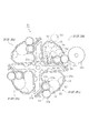
そして、現像ロータリーユニット33は、図3に示すように、感光体ドラム32a表面の静電潜像をトナー現像する現像カートリッジ37が、回転軸33aを中心に回転する区画フレーム33bにより区画されている収納位置内に複数収納(装着)されることにより構成されている。この現像ロータリーユニット33は、エンジン制御部12のCPU(制御手段)13がコントローラ部11を介して受け取ったパーソナルコンピュータPCからの画像データを含む印字命令に基づいて回転軸33aを中心に回転させることにより、感光体ドラム32aに対向させる現像カートリッジ37を切り換えて、記録用紙の片面または両面に転写して画像形成するトナー像を現像する。
なお、本実施形態において、現像カートリッジ37の基本構成としては、後述するようにその内部にトナーの調整手段たる調整フィン45を備える第1の現像カートリッジ37’と調整フィンを備えず仕切り板37eを内部に備えてロータリーユニットの回転による現像カートリッジ自体回転により収容するトナーを攪拌する第2の現像カートリッジ37’’の2種類に分けることができる。(なお、以下、単に現像カートリッジ37とした場合、現像カートリッジは第1、第2のいずれであるかを特に言及するものではない。)
In the developing
In this embodiment, as a basic configuration of the developing
例えば、この画像形成装置は、イエロー(Y)、シアン(C)、マゼンダ(M)、ブラック(K)の各色トナーを収容する現像カートリッジ37y、37m、37c、37kを現像ロータリーユニット33内に収納するとともに、この現像ロータリーユニット33を回転させて感光体ドラム32a上の静電潜像を現像する現像カートリッジ37を、その各色収容トナーを色重ねしたり選択するように切り換えることにより、カラー画像から単色画像までを形成可能な装置として利用することができる。
For example, the image forming apparatus
詳細には、現像カートリッジ37(本願の第2の現像カートリッジ37’’に相当する)は、容器37aと、現像ローラ37bと、供給ローラ37dと、仕切り板37eと、を備えている。容器37aは、現像ロータリーユニット33の区画フレーム33bにより区画された各収納空間(位置)内に収納可能に相似形状に形成されてトナーを収容する。現像ローラ37bは、現像ロータリーユニット33の回転軸33aから離隔する容器37aの外周側に回転可能に支持されており、供給ローラ37dから受け渡されるトナーを対向する感光体ドラム32aに付着させる。供給ローラ37dは、現像ロータリーユニット33の回転軸33a側で現像ローラ37bに隣接するように容器37aに回転可能に支持されており、その現像ローラ37bに圧接回転することにより周囲のトナーを磨耗帯電させて供給する。仕切り板37eは、供給ローラ37dを囲うように設置されており、回転軸33a側の空間と供給ローラ37dの設置空間の回転方向上部を連通させる状態で容器37a内のトナーの収容空間を仕切っている。
Specifically, the developing cartridge 37 (corresponding to the second developing
この構成により、この第2の現像カートリッジ37’’は、仕切り板37eにより仕切られた容器37aの外周側の空間内のトナーを供給ローラ37dが圧接回転する現像ローラ37bに供給する。また、この現像カートリッジ37’’は、現像ロータリーユニット33が図3における反時計回り方向に90度ずつ回転して180度回転したときには、容器37aの回転軸33a側および供給ローラ37d側の収容トナーを仕切り板37eの上部(図3中における下方)で一緒にした後に、さらに90度ずつ回転することにより容器37a内の収容トナーを攪拌してリフレッシュさせるとともに、その収容トナーを現像ローラ37bに供給可能に供給ローラ37d側に集める。すなわち、このように回転する現像ロータリーユニット33に装着する現像カートリッジ37’’においては、その回転により収容トナーが供給ローラ37d側に攪拌されつつ補給されるので、収容トナーを攪拌・補給などする調整動作を行うための調整装置(所謂、アジテータ装置やオーガー装置)を適宜省略することができる。ただし、この現像カートリッジ37は、調整装置を省略する場合には、少なくとも現像ローラ37bに供給するトナーが供給ローラ37dの周囲からなくなる前に、例えば、トナーカウンターによるカウント値、画像のドット数、積算する現像動作(画像形成)時間、積算する現像枚数、あるいは実測するトナーの残量などにより検出するトナーの使用量が予め設定されている値を超えたときに、現像ロータリーユニット33を回転させてトナーの補給・攪拌動作を行う必要がある。
With this configuration, the second developing
また、現像カートリッジ37には、不揮発性メモリ42と、現像側コネクタ43とが個々に内蔵されており、現像ロータリーユニット33側には、制御側コネクタ44が配置されている。不揮発性メモリ42は、製造番号等の識別情報と共に、収容するトナーの色や製造年月日や消費量などの各種情報を書換可能に記憶する。現像側コネクタ43は、それぞれ不揮発性メモリ42に接続されて記憶する情報の読出や書換を行う。制御側コネクタ44は、現像ロータリーユニット33の外周に移動しないように配置されており、いずれかの現像カートリッジ37の現像側コネクタ43に対面するときに、各種情報を接触通信又は非接触通信してやり取りする。これにより、制御ユニット10のエンジン制御部12は、現像ロータリーユニット33の収納位置に収納された現像カートリッジ37の有無や位置と共に、その現像カートリッジ37のトナーの色情報などの各種情報を適宜把握することができる。
The developing
一方、この現像カートリッジ37および現像ロータリーユニット33は、カラー画像を形成するイエロー(Y)、シアン(C)、マゼンダ(M)の各色トナーを収容する現像カートリッジ37y、37m、37cの収納位置においては、各色トナーを選択するために現像ロータリーユニット33が回転して収容トナーを攪拌・補給(調整)可能であることから、アジテータ装置やオーガー装置を備えることなく、内装する現像ローラ37bおよび供給ローラ37dを回転駆動させる。また、モノクロ画像を形成するブラック(K)のトナーを収容する現像カートリッジ37kにあっては、テキストなどを連続して画像形成する場合もあることから、本願の第1の現像カートリッジ37’としての構成を備える。すなわち、現像ロータリーユニット33を回転させることなく、収容トナーを攪拌・補給するために、アジテータ・オーガー装置としての調整フィン装置(調整手段)が設けられており、内装する現像ローラ37bおよび供給ローラ37dと共に、調整フィン45が回転駆動して収容トナーを攪拌・補給する。
On the other hand, the developing
簡単に説明すると、本願の第2の現像カートリッジ37’’を構成する現像カートリッジ37y、37m、37cの収納位置においては、現像駆動本体ギヤ51と、現像駆動ロータリーギヤ52と、現像駆動伝達ギヤ53と、現像ローラギヤ54と、供給ローラギヤ55とを互いに噛合させて連結する輪列構成により現像ローラ37bおよび供給ローラ37dが回転して動作する。その現像ローラ37bは、エンジン制御部12からの制御信号に応じて駆動する不図示の現像駆動モータ(駆動源)からの駆動力がギヤ列51〜53を介して伝達されて現像ローラギヤ54が回転することにより駆動する。また、供給ローラ37dは、その現像ローラギヤ54に噛合する供給ローラギヤ55が回転することにより駆動する。
Briefly, in the housing position of the developing
また、本願の第1の現像カートリッジ37’を構成する現像カートリッジ37kの収納位置においては、同様の輪列構成のギヤ列51〜55に加えて、駆動中継ギヤ56と、調整駆動伝達ギヤ57と、調整フィンギヤ58とを互いに噛合させて連結する輪列構成により調整フィン45が回転して動作する。この調整フィン45は、現像駆動モータからの駆動力がギヤ列51〜55を介して伝達されて現像ローラ37bおよび供給ローラ37dが回転駆動するのと同時に、その供給ローラギヤ55に噛合するギヤ列56、57を介して調整フィンギヤ58が回転することにより駆動する。
In addition, in the housing position of the developing
ここで、現像ロータリーユニット33は、回転軸33aを中心に回転するロータリーフレーム33c(図4に図示)に取り付けられており、同様に、エンジン制御部12からの制御信号に応じて駆動するロータリー駆動モータからの駆動力によりそのロータリーフレーム33cが回転することにより、装着されている現像カートリッジ37を感光体ドラム32aに対向する現像位置に順次に移動させる。
Here, the
詳細には、現像駆動伝達ギヤ53、現像ローラギヤ54および供給ローラギヤ55は、個々の現像カートリッジ37側に配置されて計4組が取り付けられている。ローラギヤ54、55は、それぞれのローラ37b、37dの一端側に同軸になるように固設されて互いに噛合する状態で容器37aに回転自在に軸支されており、現像駆動伝達ギヤ53は、このうちの現像ローラギヤ54に噛合して容器37aに回転自在に軸支されている。また、駆動中継ギヤ56、調整駆動伝達ギヤ57および調整フィンギヤ58は、現像カートリッジ37k側に1組が配置されている。同様に、調整フィンギヤ58は、第1の現像カートリッジ37’である調整フィン45の一端側に同軸になるように固設されて容器37aに回転自在に軸支されており、駆動中継ギヤ56は、供給ローラギヤ55に噛合して、また、調整駆動伝達ギヤ57はその駆動中継ギヤ56に噛合して容器37aに回転自在に軸支されている。
Specifically, the development
一方、現像駆動本体ギヤ51および現像駆動ロータリーギヤ52は、現像ロータリーユニット33側に配置されている。現像駆動ロータリーギヤ52は、現像ロータリーユニット33に装着される現像カートリッジ37毎の収納位置に対応するように計4個が取り付けられており、挿脱される現像カートリッジ37毎の現像駆動伝達ギヤ53に噛合可能に、現像ロータリーユニット33と一体回転するロータリーフレーム33cに回転自在に軸支されている。現像駆動本体ギヤ51は、図示することは省略するが、現像駆動モータに対応するように1個が取り付けられており、その現像駆動モータのモータピニオンに噛合している。また、この現像駆動本体ギヤ51は、回転してきた現像駆動ロータリーギヤ52に噛合する位置で回転自在に本体フレーム59(図5に図示)に軸支されており、その現像駆動ロータリーギヤ52を介して、動作させる現像カートリッジ37の現像ローラギヤ54および現像駆動伝達ギヤ53と連結されることにより、現像駆動モータの駆動力を伝達する伝達経路の輪列を構築する。
On the other hand, the development drive
これにより、図4(a)に示すように、現像カートリッジ37を交換する際には、その現像カートリッジ37側に配設された現像ローラギヤ54などが現像ロータリーユニット33内から挿脱されて一緒に交換される。この現像カートリッジ37が現像ロータリーユニット33に装着される際には、図4(b)に示すように、ロータリーフレーム33c側の現像駆動ロータリーギヤ52の回転軸と同軸の支持軸52aに、容器37aの両端面が揺動可能に支持されて一方向に付勢されることにより、現像駆動伝達ギヤ53がその現像駆動ロータリーギヤ52に噛合して連結される。
Accordingly, as shown in FIG. 4A, when the developing
よって、調整フィン45を備えていない第2の現像カートリッジ37’’である現像カートリッジ37y、37m、37cでは、現像位置において、現像駆動本体ギヤ51に現像駆動ロータリーギヤ52が噛合することにより、図5に示すギヤ列51〜55を介して現像ローラ37bおよび供給ローラ37dを回転駆動させる現像駆動モータの駆動力を伝達する輪列(伝達経路)を構築する。一方、調整フィン45を備える第1の現像カートリッジ37’である現像カートリッジ37kでは、現像位置において、現像駆動本体ギヤ51に現像駆動ロータリーギヤ52が噛合することにより、図6に示すギヤ列51〜58を介して現像ローラ37bおよび供給ローラ37dと共に調整フィン45を回転駆動させる現像駆動モータの駆動力を伝達する輪列(伝達経路)を構築する。すなわち、調整フィン45は、現像ローラ37bおよび供給ローラ37dと駆動源を共通利用して回転駆動する。ここで、現像駆動本体ギヤ51は、現像ローラ37bの逆回転方向には空転するようにワンウェイクラッチを内蔵しており、回転する現像駆動ロータリーギヤ52に噛合する際には逃げることができ、互いの歯先の衝突により損傷してしまうことを回避している。なお、図5や図6は、ギヤ列の噛合関係を図示するものであり、現実の位置関係を示すものではない。上述のように,現像駆動本体ギヤ51は調整フィン45を備える第1の現像カートリッジ37’であっても,調整フィン45を備えない第2の現像カートリッジ37’’であっても現像カートリッジ側に設けられる現像駆動ロータリーギヤ52と噛合可能に構成されている。なお、現像駆動本体ギヤ51が駆動する現像駆動ロータリーギヤ52は現像カートリッジ37が調整フィン45を備えるか否かによって、その駆動に要するトルクが異なる。このため,現像駆動モータは噛合する現像駆動ロータリーギヤ52に応じて現像駆動本体ギヤ51への供給トルクを変化させることができる。すなわち、現像駆動ロータリーギヤ52の構成は同じであるものの、調整フィン45を備える第1の現像カートリッジ37’の駆動トルクと、調整フィン45を備えない第2の現像カートリッジ37’’における現像駆動ロータリーギヤ52の異なる駆動トルクが供給される。後述するようにCPU13は、収容された現像カートリッジの情報に基づき、現像カートリッジに応じたトナーの攪拌制御を実行する。この際、上記駆動に要するトルクを検出することによりCPU13に収容されている現像カートリッジの種類を把握させることも可能である。
Therefore, in the developing
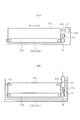
この実施例の画像形成装置では、この現像ロータリーユニット33は、すべての現像カートリッジ37内に同色のトナーを収容して画像形成可能に構成されている。例えば、現像カートリッジ37y、37m、37cの収納位置に収納可能な、すなわち、調整フィン45を備えていない第2の現像カートリッジ37’’である現像カートリッジ37K内に、第1の現像カートリッジ37’である現像カートリッジ37kと同色のブラック(K)のトナーを収容して、図7に示すように、その現像カートリッジ37Kをその現像カートリッジ37kの収納位置も含めて装着することができる。この場合には、現像ロータリーユニット33を回転して感光体ドラム32a上の静電潜像を現像する現像カートリッジ37Kを順次に切り換えることにより、モノクロ画像を形成する専用機として利用することができる。なお、この現像ロータリーユニット33は、図8に示すように、現像カートリッジ37kはそのまま装着すると共に、現像カートリッジ37y、37m、37cのすべて、あるいは一部を現像カートリッジ37Kに交換して、各色トナーで色分けした多色画像や単色画像を形成可能な装置として利用することもできる。
In the image forming apparatus of this embodiment, the developing
具体的には、エンジン制御部12のCPU13は、電源投入後にはROM14内の制御プログラムに従って各種制御動作を実行するようになっており、電源投入時や現像カートリッジ37の交換時には、コネクタ43、44を介する非接触通信を行うことにより、現像ロータリーユニット33の収納位置における現像カートリッジ37の有無を本体メモリ15内に保持(記憶)する。また、このCPU13は、コネクタ43、44を介して各現像カートリッジ37の不揮発性メモリ42内に書き込まれている各種情報を順次に読み出して、現像カートリッジ37毎の位置情報や調整フィン45の有無(現像カートリッジの種類の判別)やトナーの色情報や消費量(残量)などを本体メモリ15内に保持する。さらに、このCPU13は、画像形成動作中や画像形成終了後には、その画像形成により消費したトナー量などの各種情報をコネクタ43、44を介して各現像カートリッジ37の不揮発性メモリ42内に書き込んで書き換える。すなわち、CPU13が制御手段と共に確認手段を構成している。なお、現像ロータリーユニット33に装着する現像カートリッジ37y、37m、37cは、カラー画像を形成する際の最適な色重ね順序があることから、それぞれの収納可能な位置を機械的に制限してもよく、この場合には、現像カートリッジ37Kはその制限を受けることなく収納可能にすればよい。
Specifically, the
このとき、CPU13は、現像ロータリーユニット33にイエロー(Y)、シアン(C)、マゼンダ(M)、ブラック(K)の各色トナーを収容する現像カートリッジ37y、37m、37c、37kがセットされたことを把握している場合には、一般的な画像形成制御を実行して、コントローラ部11から送られてきた画像データに応じて現像ロータリーユニット33を回転させることにより、カラー画像や多色画像や単色画像を記録用紙の片面または両面に記録形成する。言い換えると、現像ロータリーユニット33に装着された各色トナーの現像カートリッジ37は、画像データの印字命令を受ける度に、その画像データに基づく画像の種別に応じて適宜切り換えられて動作する。これにより、現像カートリッジ37y、37m、37cでは、現像ロータリーユニット33の回転に伴って現像ローラ37bに収容トナーを供給する供給ローラ37dにも適宜収容トナーが補給される。一方、モノクロ画像のトナー像を現像する現像カートリッジ37kは、現像ロータリーユニット33が回転することなく画像形成動作が継続されるので、感光体ドラム32aに対向する現像位置では現像ローラ37bと共に調整フィン45も回転駆動されて収容トナーが攪拌されつつ供給ローラ37dに補給される。
At this time, the
一方、本実施形態の画像形成装置においては、現像ロータリーユニット33に現像カートリッジ37y、37m、37c、37kに代えて、調整フィン45を備えずにブラック(K)のトナーを収容する現像カートリッジ37K(すなわち第2の現像カートリッジ37’’に相当する)を収容し、単色の画像形成を行うことができる。この場合、CPU13は、現像ロータリーユニット33に現像カートリッジ37y、37m、37c、37kに代えて、調整フィン45を備えずにブラック(K)のトナーを収容する現像カートリッジ37’’がセットされたことを把握している場合には、同色(ブラックK)のトナーを収容する現像カートリッジ37Kがすべての収納位置に装着された場合の画像形成制御を実行する。すなわち、コントローラ部11から送られてきた画像データに応じて現像ロータリーユニット33を適宜回転させることにより、単色画像を記録用紙の片面または両面に記録形成する。この場合、各現像カートリッジ37Kにおけるトナー色や要求される攪拌制御がいずれも同じとなるため、印字枚数やトナー消費量によって印字に基づき、開始する現像カートリッジを所定のものに選択するという必要はない。
On the other hand, in the image forming apparatus of the present embodiment, instead of the developing
具体的には、図9のフローチャートに示すように、コントローラ部11からモノクロ画像の画像データの印字命令を受け取ると(ステップS11)、現像ロータリーユニット33を回転させて次の現像カートリッジ37Kを感光体ドラム32aに対向する現像位置に移動させて切り換えた後に(ステップS12)、受け取った画像データを印字するための用紙搬送装置20や画像記録装置30の駆動制御を実行して記録用紙の片面または両面に画像形成する(ステップS13)。
Specifically, as shown in the flowchart of FIG. 9, when a print command for monochrome image data is received from the controller unit 11 (step S11), the developing
次いで、この記録用紙毎の印字処理が終了する度に、受け取った画像データの印字処理は完了したか否かを確認して(ステップS14)、完了していた場合には、このままこの画像形成制御を終了する。一方、完了していなかった場合には、供給ローラ37dの設置空間内に収容トナーを補給することなく同一の現像カートリッジ37Kを使用し続けて画像形成動作を完了することのできる画像形成量を超えたか否か、例えば、A4サイズの記録用紙を使用する場合で、印字枚数が未だ40枚以下、かつ(AND条件)、画像のドット数などに基づくトナーの消費量が未だ10g以下であるか否かを確認する(ステップS15)。なお、本実施形態では、双方の条件を満たすAND条件で判断しているが、これに限るものではないことはいうまでもなく、どちらか一方の条件を満たすか否かのOR条件で判断するようにしてもよい。
Next, every time the printing process for each recording sheet is completed, it is confirmed whether or not the printing process for the received image data has been completed (step S14). Exit. On the other hand, if it has not been completed, the image forming amount that can complete the image forming operation by using the same developing cartridge 37K without replenishing the toner contained in the installation space of the
そして、その双方の条件を満たしている場合には、ステップS13に戻って、現像ロータリーユニット33を回転させることなく、同一の現像カートリッジ37Kを使用しての印字処理を継続する。一方、いずれか一方の条件を満たさなくなって、同一の現像カートリッジ37Kを使用して受け取った画像データの印字処理を完了することができない場合には、ステップS12に戻って、現像ロータリーユニット33を回転させて次の現像カートリッジ37Kを現像位置に移動させる切換動作を行った後に、残っている画像データの印字処理を継続する。このとき、現像カートリッジ37Kの切換は、隣接する現像カートリッジ37Kを現像位置に移動させればよいので、迅速に切換動作を終了することができ、例えば、連続する記録用紙の間(所謂、紙間)の搬送タイミング中に終了することができ、見かけ上の画像形成速度(所謂、スループット)を低下させることがない。また、使用する現像カートリッジ37Kは、すべて同一の調整フィン45を備えていないタイプのものであるので、画像形成制御を変えることなく、印字処理を継続することができる。
If both conditions are satisfied, the process returns to step S13, and the printing process using the same developing cartridge 37K is continued without rotating the developing
したがって、現像ロータリーユニット33のすべての収納位置には、調整フィン45を備えないでブラック(K)のトナーを収容する現像カートリッジ37Kを装着することができ、モノクロ画像用の現像カートリッジ37Kの装着数を増加させることができる。すなわち、モノクロ画像を形成するブラック(K)のトナーの収容量を増加することができ、現像カートリッジ37kのみの場合よりも大量の画像形成を行うことができる。そして、CPU13は、オペレータが操作パネルなどから設定作業を行うことを要求することなく、その現像ロータリーユニット33に装着された現像カートリッジ37を自動認識して、画像形成動作中に現像ロータリーユニット33を適宜回転させることにより、カラー画像や大量のモノクロ画像を記録用紙に形成することができる。
Therefore, a developing cartridge 37K that contains black (K) toner can be mounted in all the storage positions of the developing
具体的には、例えば、調整フィン45を備える現像カートリッジ37kの場合には、ブラック(K)のトナーを230g収容して、画像記録面のうちの5%にドット印字を行うときに、A4サイズの記録用紙で約5,500枚に画像形成することができる。これに対して、調整フィン45を備えない現像カートリッジ37Kの場合には、調整フィン45などの機構部分とトナーの流動性の阻害による収容量の減少がなく、ブラック(K)のトナーを250g収容することができ、同様なドット印字を行うと、A4サイズの記録用紙で約6,000枚に画像形成することができる。この結果、現像ロータリーユニット33に、4本の現像カートリッジ37Kを装着する場合には、トータルで24,000枚に連続して画像形成することができる。
Specifically, for example, in the case of the developing
このように本実施形態においては、装着した現像カートリッジ37を自動認識して現像ロータリーユニット33を適宜回転させることにより、特別な設定操作を行うことなく、カラー画像や単色画像を形成することができ、その現像ロータリーユニット33のすべての収納位置に、同色のブラック(K)のトナーを収容する現像カートリッジ37Kを装着する場合には、現像カートリッジ37を交換することによるトナーの補充作業を小まめに行うことなく、大量のモノクロ画像を記録用紙の片面または両面に形成することができる。 なお、上記のように現像ロータリーユニット33のすべての収容位置に現像カートリッジ37Kを装着した実施の形態を説明したが、本願はこれに限定されるものではない。 すなわち、調整フィン45を備えずブラック(K)のトナーを有する現像カートリッジ37Kがロータリーユニットに収容可能であり、印字命令に基づき、収容されているトナーの攪拌の要否をCPU13が判別し、ロータリーユニット33の回転を適宜利用して攪拌動作を実行するように構成されていればよい。このように構成すれば、単一の現像カートリッジでのトナーの収容量比較的大量に確保することが可能であるため、大量のモノクロ画像を形成することができるという効果を有することは言うまでもない。特に、複数の調整フィン45を備えない現像カートリッジ37Kを複数収容し、攪拌のためのロータリーユニット33の回転を利用して適宜現像に使用されるカートリッジを交換して使用することで、トナーの補充作業を小まめに行うことなく、大量のモノクロ画像を記録用紙の片面または両面に形成することができる。
As described above, in this embodiment, by automatically recognizing the mounted developing
これまで本発明の一実施形態について説明したが、本発明は上述の実施形態に限定されず、その技術的思想の範囲内において種々異なる形態にて実施されてよいことは言うまでもない。 Although one embodiment of the present invention has been described so far, it is needless to say that the present invention is not limited to the above-described embodiment, and may be implemented in various forms within the scope of the technical idea.
10 制御ユニット
11 コントローラ部
12 エンジン制御部
13 CPU
14 RAM
15 本体メモリ
16 RAM
20 用紙搬送装置
30 画像記録装置
31 露光ユニット
32a 感光体ドラム
33 現像ロータリーユニット
33a 回転軸
34 中間転写ベルト
35 転写ローラ
36 定着ローラ対
37、37y、37m、37c、37k、37K 現像カートリッジ
37a 容器
37b 現像ローラ
37d 供給ローラ
37e 仕切り板
42 不揮発性メモリ
43 現像側コネクタ
44 制御側コネクタ
45 調整フィン
51 現像駆動本体ギヤ
52 現像駆動ロータリーギヤ
53 現像駆動伝達ギヤ
54 現像ローラギヤ
55 供給ローラギヤ
56 駆動中継ギヤ
57 調整駆動伝達ギヤ
58 調整フィンギヤ
59 本体フレーム
P 記録形成位置
DESCRIPTION OF
14 RAM
15
20
Claims (4)
異なる色のトナーを収容する現像カートリッジをロータリーユニットに収納することにより、カラー画像、多色画像、あるいは単色画像を形成可能に構成されるとともに、単色画像を形成する色のトナーを収容する現像カートリッジのみに、当該収容トナーを連続して画像形成可能に調整する調整手段を配設する一方、他の現像カートリッジの収容トナーは画像形成時のロータリーユニットの回転に伴って天地を反転させることにより該収容トナーの調整動作を行う画像形成装置であって、
調整手段を備える現像カートリッジの収容位置にも、該調整装置を備えていない現像カートリッジを収納可能にしたことを特徴とする画像形成装置。 A surface of the recording medium formed by forming a latent electrostatic image on the surface and carrying a toner image obtained by developing the latent electrostatic image, and developing the electrostatic latent image on the surface of the carrier with toner attached thereto A plurality of developing cartridges for forming a toner image to be transferred to the toner cartridge, and the plurality of developing cartridges are housed around a rotation shaft and rotated around the rotation shaft so that any one of the developing cartridges faces the surface of the carrier. A rotary unit, and a control means for controlling the rotation of the rotary unit and the driving of the developing cartridge to form a toner image,
A developer cartridge that accommodates toner of a color that forms a single-color image while being capable of forming a color image, a multicolor image, or a single-color image by housing a developer cartridge that contains toner of different colors in a rotary unit Only the adjustment means for continuously adjusting the accommodated toner so that the image can be formed is provided, while the accommodated toner of the other developing cartridges is reversed by rotating the top and bottom with the rotation of the rotary unit at the time of image formation. An image forming apparatus that performs an adjustment operation of stored toner,
An image forming apparatus characterized in that a developing cartridge not equipped with the adjusting device can be accommodated in a housing position of a developing cartridge equipped with adjusting means.
前記制御手段は、該確認手段からの情報に基づいて、ロータリーユニットの回転動作を制御することを特徴とする請求項1または2に記載の画像形成装置。 Having confirmation means for confirming the developing cartridge stored in the rotary unit;
The image forming apparatus according to claim 1, wherein the control unit controls a rotation operation of the rotary unit based on information from the confirmation unit.
Priority Applications (3)
| Application Number | Priority Date | Filing Date | Title |
|---|---|---|---|
| JP2005063569A JP2005292815A (en) | 2004-03-10 | 2005-03-08 | Image forming apparatus |
| EP05005236A EP1574910A2 (en) | 2004-03-10 | 2005-03-10 | Image forming apparatus |
| US11/078,659 US7123863B2 (en) | 2004-03-10 | 2005-03-10 | Image forming apparatus with rotary unit that can accommodate a plurality of development cartridges |
Applications Claiming Priority (2)
| Application Number | Priority Date | Filing Date | Title |
|---|---|---|---|
| JP2004067239 | 2004-03-10 | ||
| JP2005063569A JP2005292815A (en) | 2004-03-10 | 2005-03-08 | Image forming apparatus |
Publications (1)
| Publication Number | Publication Date |
|---|---|
| JP2005292815A true JP2005292815A (en) | 2005-10-20 |
Family
ID=35325745
Family Applications (1)
| Application Number | Title | Priority Date | Filing Date |
|---|---|---|---|
| JP2005063569A Pending JP2005292815A (en) | 2004-03-10 | 2005-03-08 | Image forming apparatus |
Country Status (1)
| Country | Link |
|---|---|
| JP (1) | JP2005292815A (en) |
-
2005
- 2005-03-08 JP JP2005063569A patent/JP2005292815A/en active Pending
Similar Documents
| Publication | Publication Date | Title |
|---|---|---|
| US7995942B2 (en) | Developing apparatus of image forming apparatus and supplying method of toner | |
| JP2005257799A (en) | Image forming apparatus | |
| US7065304B2 (en) | Image forming apparatus and image forming method | |
| US7123863B2 (en) | Image forming apparatus with rotary unit that can accommodate a plurality of development cartridges | |
| US7242872B2 (en) | Image forming apparatus with changeover control for development cartridges | |
| JP2005257875A (en) | Image forming apparatus | |
| JP4078097B2 (en) | Power transmission device and image forming apparatus | |
| JP2005292816A (en) | Image forming apparatus | |
| JP2005292815A (en) | Image forming apparatus | |
| US7437102B2 (en) | Image forming apparatus with controlled adjustment of toner stored in developing cartridge | |
| JP2005257876A (en) | Image forming apparatus | |
| JP4390662B2 (en) | Image forming apparatus | |
| JP3288688B2 (en) | Image forming apparatus and frame of image forming apparatus | |
| JP3093186B2 (en) | Image recording device | |
| JP3288639B2 (en) | Image forming device | |
| JP2005266286A (en) | Image forming apparatus | |
| JP2005266287A (en) | Image forming apparatus | |
| JP2837961B2 (en) | Image recording device | |
| JP4215091B2 (en) | Image forming apparatus and image forming method | |
| JP2008254880A (en) | Image forming apparatus | |
| JP2006126555A (en) | Image forming apparatus | |
| JP2006126554A (en) | Image forming apparatus | |
| JP4604653B2 (en) | Image forming apparatus | |
| JP4062351B2 (en) | Image forming apparatus and image forming method | |
| JP2005257796A (en) | Image forming apparatus |