JP2005292813A - Projection optical system and image projection apparatus - Google Patents
Projection optical system and image projection apparatus Download PDFInfo
- Publication number
- JP2005292813A JP2005292813A JP2005062395A JP2005062395A JP2005292813A JP 2005292813 A JP2005292813 A JP 2005292813A JP 2005062395 A JP2005062395 A JP 2005062395A JP 2005062395 A JP2005062395 A JP 2005062395A JP 2005292813 A JP2005292813 A JP 2005292813A
- Authority
- JP
- Japan
- Prior art keywords
- lens
- lens group
- optical system
- projection optical
- projection
- Prior art date
- Legal status (The legal status is an assumption and is not a legal conclusion. Google has not performed a legal analysis and makes no representation as to the accuracy of the status listed.)
- Pending
Links
Images


Classifications
-
- G—PHYSICS
- G02—OPTICS
- G02B—OPTICAL ELEMENTS, SYSTEMS OR APPARATUS
- G02B17/00—Systems with reflecting surfaces, with or without refracting elements
- G02B17/08—Catadioptric systems
-
- G—PHYSICS
- G02—OPTICS
- G02B—OPTICAL ELEMENTS, SYSTEMS OR APPARATUS
- G02B13/00—Optical objectives specially designed for the purposes specified below
- G02B13/22—Telecentric objectives or lens systems
-
- G—PHYSICS
- G03—PHOTOGRAPHY; CINEMATOGRAPHY; ANALOGOUS TECHNIQUES USING WAVES OTHER THAN OPTICAL WAVES; ELECTROGRAPHY; HOLOGRAPHY
- G03B—APPARATUS OR ARRANGEMENTS FOR TAKING PHOTOGRAPHS OR FOR PROJECTING OR VIEWING THEM; APPARATUS OR ARRANGEMENTS EMPLOYING ANALOGOUS TECHNIQUES USING WAVES OTHER THAN OPTICAL WAVES; ACCESSORIES THEREFOR
- G03B21/00—Projectors or projection-type viewers; Accessories therefor
- G03B21/14—Details
- G03B21/28—Reflectors in projection beam
-
- G—PHYSICS
- G03—PHOTOGRAPHY; CINEMATOGRAPHY; ANALOGOUS TECHNIQUES USING WAVES OTHER THAN OPTICAL WAVES; ELECTROGRAPHY; HOLOGRAPHY
- G03B—APPARATUS OR ARRANGEMENTS FOR TAKING PHOTOGRAPHS OR FOR PROJECTING OR VIEWING THEM; APPARATUS OR ARRANGEMENTS EMPLOYING ANALOGOUS TECHNIQUES USING WAVES OTHER THAN OPTICAL WAVES; ACCESSORIES THEREFOR
- G03B21/00—Projectors or projection-type viewers; Accessories therefor
- G03B21/54—Accessories
- G03B21/56—Projection screens
- G03B21/60—Projection screens characterised by the nature of the surface
- G03B21/62—Translucent screens
Landscapes
- Physics & Mathematics (AREA)
- General Physics & Mathematics (AREA)
- Optics & Photonics (AREA)
- Lenses (AREA)
Abstract
【課題】 小型でありながら、良好な結像性能による広角度での投影を達成することを課題とする。
【解決手段】 少なくとも投影側から順に配列された負の屈折力を有する第1レンズ群GR1と負の屈折力を有する第2レンズ群GR2とを備えたレトロフォーカス型の投影光学系1であって、上記第1レンズ群は投影側に凹面を向けると共に該凹面が非球面の反射面とされた負メニスカスレンズG1で構成される。
【選択図】図1
PROBLEM TO BE SOLVED: To achieve projection at a wide angle with good imaging performance while being small.
A retrofocus projection optical system 1 includes a first lens group GR1 having negative refractive power and a second lens group GR2 having negative refractive power, which are arranged in order from the projection side. The first lens group includes a negative meniscus lens G1 having a concave surface directed toward the projection side and the concave surface being an aspherical reflecting surface.
[Selection] Figure 1
Description
本発明は新規な投影光学系及び画像投影装置に関する。詳しくは、良好な結像性能による広角度での投影を達成すると共に小型化を可能にする技術に関する。 The present invention relates to a novel projection optical system and image projection apparatus. More specifically, the present invention relates to a technique that achieves wide-angle projection with good imaging performance and enables miniaturization.
近時の投影光学系にあっては、一つの条件として広角化が望まれている。画像投影装置に適用した場合、広角化によって、リアプロジェクションテレビ、すなわち、透過型スクリーンの背面から画像を投影して当該画像を正面から鑑賞する装置にあっては、スクリーンと投影光学系との間の距離を短くしながら大型のスクリーンに画像を投影することができて小型化、特に、奥行方向の小型化を達成することができ、また、投写型のフロントプロジェクター、すなわち、反射型スクリーンに投影した画像を画像投影装置の側から鑑賞する装置にあっては、スクリーンと画像投影装置との間の大きな距離を取れない場所であっても大型のスクリーンへの投影が可能であり、画像鑑賞のための場所に空間的な制約が少ないという利点を有する。 In recent projection optical systems, a wide angle is desired as one condition. When applied to an image projection device, the rear projection television, that is, a device for projecting an image from the back of a transmissive screen and viewing the image from the front by widening the angle, between the screen and the projection optical system. The image can be projected on a large screen while shortening the distance of the projector, so that the size can be reduced, especially in the depth direction. In addition, the projection can be projected onto a front projector, that is, a reflective screen. In the device for viewing the image from the image projection device side, it can be projected onto a large screen even in a place where a large distance between the screen and the image projection device cannot be obtained. This has the advantage that there are few spatial constraints on the location.
広角化を実現した投影光学系として特許文献1には非球面ミラーを屈折光学系と組み合わせた投影光学系と、複数の非球面及び球面ミラーを組み合わせた投影光学系が示されている。また、特許文献2には、非球面ミラーを屈折光学系と組み合わせた投影光学系が示され、さらに、特許文献3には、4枚の非球面ミラーで構成された投影光学系が示されている。
ところで、従来のように、1枚の非球面ミラーと屈折光学系とを組み合わせた投影光学系にあっては、屈折光学系のみによって構成した場合と比較して、色収差を取りやすく、且つ、広角化が容易である。その反面、1面の非球面ミラーが発散作用のほとんどを担うため、歪曲や像面湾曲の収差発生量が大きく像質を悪くする傾向があった。そのため、歪曲収差や像面湾曲の補正を適切にするには、非球面ミラーの屈折力を緩く(曲率半径を大きく)しなければならず、非球面ミラーが大型化し、そのために、非球面ミラーを配置するスペースが大きくなってしまう。このことは、例えば、リアプロジェクションテレビに適用した場合、スクリーンの下部又は上部に高いスペースが必要になることを意味する。 By the way, in the conventional projection optical system in which a single aspherical mirror and a refractive optical system are combined, chromatic aberration can be easily obtained compared with a case where only a refractive optical system is used, and a wide angle is obtained. Is easy. On the other hand, since one aspherical mirror is responsible for most of the diverging action, the amount of distortion and curvature of field is large and the image quality tends to deteriorate. For this reason, in order to properly correct distortion aberration and field curvature, the refractive power of the aspherical mirror must be relaxed (the radius of curvature is increased), and the aspherical mirror becomes larger, so that the aspherical mirror The space to arrange will become larger. This means that, for example, when applied to a rear projection television, a high space is required at the bottom or top of the screen.
また、複数の非球面ミラーを使用する方法は、屈折光学系での構成は無いため、原理的に色収差は発生せず、かつ、レンズによる吸収も全く無い。しかしミラーのみでの構成となるため、非常に製造時の誤差に敏感であり、調整に手間を要するため、一般のテレビのような量産性を主体とする光学系には不向きである。また、特許文献3にあっては4枚のミラーを縦方向に配置するため、物理的にスクリーン下部又は上部を低くすることが困難となる。
Further, the method using a plurality of aspherical mirrors does not have a refracting optical system, so that chromatic aberration does not occur in principle and there is no absorption by the lens. However, since it is composed only of mirrors, it is very sensitive to errors in manufacturing and requires labor for adjustment, so it is not suitable for an optical system mainly for mass production such as a general television. In
そこで、本発明は、小型でありながら、良好な結像性能による広角度での投影を達成することを課題とする。 Therefore, an object of the present invention is to achieve wide-angle projection with good imaging performance while being small.
本発明投影光学系は、上記した課題を解決するために、少なくとも投影側から順に配列された負の屈折力を有する第1レンズ群と負の屈折力を有する第2レンズ群とを備えたレトロフォーカス型の投影光学系であって、上記第1レンズ群は投影側に凹面を向けるとともに該凹面が非球面の反射面とされた負メニスカスレンズで構成されるようにしたものである。 In order to solve the above-described problem, the projection optical system of the present invention has a retro including at least a first lens group having negative refractive power and a second lens group having negative refractive power arranged in order from the projection side. In the focus type projection optical system, the first lens group is configured by a negative meniscus lens having a concave surface directed toward the projection side and the concave surface being an aspheric reflecting surface.
また、本発明画像投影装置は、上記した課題を解決するために、画像を形成する画像形成部と、上記画像形成部で形成された画像を投影する投影光学系を備えた画像投影装置であって、上記投影光学系が、少なくとも投影側から順に配列された負の屈折力を有する第1レンズ群と負の屈折力を有する第2レンズ群とを備えたレトロフォーカス型の投影光学系であって、上記第1レンズ群は投影側に凹面を向けるとともに該凹面が非球面の反射面とされた負メニスカスレンズで構成されるようにしたものである。 In order to solve the above-described problems, the image projection apparatus of the present invention is an image projection apparatus that includes an image forming unit that forms an image and a projection optical system that projects an image formed by the image forming unit. Thus, the projection optical system is a retrofocus type projection optical system including at least a first lens group having a negative refractive power and a second lens group having a negative refractive power arranged in order from the projection side. The first lens group is configured by a negative meniscus lens having a concave surface directed toward the projection side and the concave surface being an aspheric reflecting surface.
従って、本発明にあっては、各種収差が良好に補正された高画質な画像の広角度での投影が可能であると共に小型に構成することができる。 Therefore, in the present invention, it is possible to project a high-quality image in which various aberrations are well corrected, at a wide angle, and to have a small size.
本発明投影光学系は、少なくとも投影側から順に配列された負の屈折力を有する第1レンズ群と負の屈折力を有する第2レンズ群とを備えたレトロフォーカス型の投影光学系であって、上記第1レンズ群は投影側に凹面を向けるとともに該凹面が非球面の反射面とされた負メニスカスレンズで構成されることを特徴とする。 The projection optical system according to the present invention is a retrofocus type projection optical system including at least a first lens group having a negative refractive power and a second lens group having a negative refractive power arranged in order from the projection side. The first lens group includes a negative meniscus lens having a concave surface directed toward the projection side and the concave surface being an aspheric reflecting surface.
また、本発明画像投影装置は、画像を形成する画像形成部と、上記画像形成部で形成された画像を投影する投影光学系を備えた画像投影装置であって、上記投影光学系が、少なくとも投影側から順に配列された負の屈折力を有する第1レンズ群と負の屈折力を有する第2レンズ群とを備えたレトロフォーカス型の投影光学系であって、上記第1レンズ群は投影側に凹面を向けるとともに該凹面が非球面の反射面とされた負メニスカスレンズで構成されることを特徴とする。 The image projection apparatus of the present invention is an image projection apparatus including an image forming unit that forms an image and a projection optical system that projects an image formed by the image forming unit, and the projection optical system includes at least A retrofocus type projection optical system comprising a first lens group having negative refractive power and a second lens group having negative refractive power arranged in order from the projection side, wherein the first lens group projects A concave meniscus lens having a concave surface directed to the side and an aspherical reflecting surface is provided.
従って、本発明にあっては、投影作用の最終段を担い広角化に主要な役割を有する反射面を屈折率n(>1)を有する負メニスカスレンズの非球面を有する凹面に形成して、光束が凸面の屈折面を上記反射面による反射の前後2度透過して投影されるようにしたので、この負メニスカスレンズによるトータルの屈折力を反射面のみによる屈折力と同じにした場合、言い換えれば、光束の広がりを同じにした場合、負メニスカスレンズの曲率半径を屈折率nの分だけ大きくすることができる。これにより、広角度を同じにした場合、収差発生量を最終段の光束をミラーのみによって広げる場合に比較して、約2/3に低減することができ、高画質、低歪曲での投影を行うことが可能である。また、このことは非球面反射面の小径化を達成することができると共にサグ量の減少も可能とし、小型化を達成
することができる。
Therefore, in the present invention, the reflecting surface that plays the final stage of the projection action and plays a major role in widening the angle is formed on the concave surface having the aspherical surface of the negative meniscus lens having the refractive index n (> 1), Since the light beam is projected through the convex refracting surface twice before and after the reflection by the reflecting surface, the total refractive power by the negative meniscus lens is made the same as the refractive power by the reflecting surface only, in other words For example, when the spread of the light flux is the same, the radius of curvature of the negative meniscus lens can be increased by the refractive index n. As a result, when the wide angle is the same, the amount of aberration generated can be reduced to about 2/3 compared with the case where the final stage light beam is spread only by the mirror, and projection with high image quality and low distortion can be achieved. Is possible. In addition, this can achieve a reduction in the diameter of the aspherical reflecting surface and also reduce the amount of sag, thereby achieving a reduction in size.
請求項2及び請求項20に記載した発明にあっては、上記第2レンズ群より像側に、像側に向かって順に、正の屈折力を有する第3レンズ群と正の屈折力を有する第4レンズ群が配列され、f(all)を全系の焦点距離、φ1を第1レンズ群の屈折力、φ2を第2レンズ群の屈折力、φ12を第1レンズ群と第2レンズ群の合成屈折力、φ34を第3レンズ群と第4レンズ群の合成屈折力、Tmaxを負メニスカスレンズの最大像高の光軸に平行な厚み、T0を負メニスカスレンズの軸上厚み、krを反射面の非球面円錐定数として、以下の条件式(1)0.02<f(all)・|φ1|<0.3、(2)3.0<φ12/φ34<20、(3)−2.0<f(all)・φ12<−0.2、(4)0.1<Tmax/T0<5.0及び(5)−30<kr<0を満足するので、各種収差の補正をさらに良好に行うことができる。特に、歪曲、像面湾曲の収差補正を適正に行うことができる。
In the invention described in
請求項3及び請求項4に記載した発明にあっては、第1レンズ群を構成している負メニスカスレンズの屈折面が非球面で形成されており、ktを屈折面の非球面円錐定数として、条件式(6)−15.0<kt<15.0を満足するので、歪曲収差及び像面湾曲の補正をさらに適正に行うことができる。
In the invention described in
請求項5及び請求項6に記載の発明にあっては、第1レンズ群の負メニスカスレンズの反射面の非球面が、A3Rを負メニスカスレンズの反射面の3次非球面係数として、条件式(7)0.0<A3R<1.0×10⁻¹²を満足する奇数次項を含むので、歪曲収差、像面湾曲等の収差補正が容易になる。 In the fifth and sixth aspects of the invention, the aspherical surface of the reflecting surface of the negative meniscus lens in the first lens group has a conditional expression where A3R is the third-order aspherical coefficient of the reflecting surface of the negative meniscus lens. (7) Since odd-numbered terms satisfying 0.0 <A3R <1.0 × 10⁻¹² are included, correction of aberrations such as distortion and curvature of field becomes easy.
請求項7及び請求項8に記載した発明にあっては、第1レンズ群の負メニスカスレンズの屈折面の非球面が、A3Tを負メニスカスレンズの屈折面の3次非球面係数として、条件式(8)0.0<A3T<1.0×10⁻¹²を満足する奇数次項を含むので、歪曲収差、像面湾曲等の収差補正が容易になる。
In the invention described in
請求項9及び請求項10に記載した発明にあっては、第2レンズ群を構成するレンズの各面のうち、少なくとも1面が非球面で形成されているので、良好な収差補正が可能になると共にレンズの枚数を減らすことができる。
In the invention described in
請求項11及び請求項12に記載した発明にあっては、第2レンズ群を構成するレンズの各面のうち、少なくとも1面が奇数次の項を含む非球面で形成されているので、良好な収差補正が可能になると共にレンズの枚数を減らすことができる。 In the invention described in claims 11 and 12, at least one of the surfaces of the lenses constituting the second lens group is formed of an aspherical surface including odd-numbered terms. Aberration correction can be performed and the number of lenses can be reduced.
請求項13及び請求項14に記載した発明にあっては、第4レンズ群を構成するレンズの各面のうち、少なくとも1面が非球面で形成されているので、良好な収差補正が可能になると共にレンズの枚数を減らすことができる。 In the invention described in claims 13 and 14, at least one of the surfaces of the lenses constituting the fourth lens group is formed as an aspheric surface, so that favorable aberration correction is possible. And the number of lenses can be reduced.
請求項15及び請求項16に記載した発明にあっては、第4レンズ群の正レンズのうちの少なくとも1枚が、ΔP={Θ−(0.6444−0.001689・ν(凸))}×100、Θ=(ng−nF)/(nF−nC)、ν(凸)を正レンズのd線(587.6nm)のアッベ数、ngを正レンズのg線(435.84nm)の屈折率、nFを正レンズのF線(486.13nm)の屈折率、nCを正レンズのC線(656.28nm)の屈折率として、条件式(9)0.7<ΔP<6.0及び(10)60<ν(凸)<100を満足するので、色収差の補正を良好に行うことができる。
In the invention described in
請求項17及び請求項18に記載し発明にあっては、第2レンズ群より像側の適宜の位置に光路を折り曲げる光路折曲手段を介挿したので、奥行方向の小型化を図ることができる。
In the invention described in
以下に、本発明を実施するための最良の形態について添付図面を参照して説明する。 The best mode for carrying out the present invention will be described below with reference to the accompanying drawings.
本発明投影光学系は、少なくとも投影側から順に配列された負の屈折力を有する第1レンズ群GR1と負の屈折力を有する第2レンズ群GR2とを備えたレトロフォーカス型の投影光学系であって、上記第1レンズ群GR1は投影側に凹面s3を向けるとともに該凹面s3が非球面の反射面とされた負メニスカスレンズG1で構成されることを基本構成とするものである。 The projection optical system of the present invention is a retrofocus type projection optical system including a first lens group GR1 having negative refractive power and a second lens group GR2 having negative refractive power, which are arranged in order from the projection side. The first lens group GR1 is basically composed of a negative meniscus lens G1 having a concave surface s3 facing the projection side and the concave surface s3 being an aspheric reflecting surface.
上記したように、従来の非球面ミラーと屈折光学系とを組み合わせたもの或いは複数の非球面ミラーを組み合わせたものにあっては、主に最も投影側(物体側)の非球面ミラーの1面にフィールドコンプレッサー的な要素を大部分持たせることで、広角化を達成していた。しかし、かかる方法の場合、1面の反射面のみに広角化のための屈折力を負担させるので、歪曲や像面湾曲の収差発生量が大きく像質を悪くする傾向があった。 As described above, in a combination of a conventional aspherical mirror and a refractive optical system or a combination of a plurality of aspherical mirrors, one surface of the most aspherical mirror on the projection side (object side) is mainly used. A wide angle was achieved by having most of the field compressor elements. However, in the case of such a method, only one reflecting surface bears the refractive power for widening the angle, so that there is a large amount of distortion and curvature of field, and the image quality tends to deteriorate.
本発明では、収差発生量を抑えるために、投影側の非球面ミラーを屈折率n(>1)を有する負メニスカスレンズG1に置き換え、非球面を持つ凹面s3を反射面とすることによって、従来にあった上記の問題を克服した。 In the present invention, in order to reduce the amount of aberration generated, the aspherical mirror on the projection side is replaced with a negative meniscus lens G1 having a refractive index n (> 1), and the concave surface s3 having an aspherical surface is used as a reflecting surface. Overcoming the above problem.
ミラーの焦点距離(f)は、f=−r/2で表されるが、屈折率nを持ち、裏面に反射面が有る場合f=−r/2nとなる。つまり反射面の屈折力が同じであるならば、屈折率nの分だけ曲率半径rを大きくすることが出来る。これにより収差発生量もミラーだけの場合と比較して、約2/3低減されるため、高画質、低歪曲の光学系の達成が可能となる。また,これは非球面の径の小型化を達成すると共に、サグ量(この場合、ミラー端部からの曲面の高さ)の減少も可能であり、例えば、リアプロジェクションテレビに適用した場合、薄型化を達成することができる。 The focal length (f) of the mirror is represented by f = −r / 2, and has f = −r / 2n when it has a refractive index n and a reflecting surface on the back surface. That is, if the reflecting surfaces have the same refractive power, the radius of curvature r can be increased by the refractive index n. As a result, the amount of aberration generated is reduced by about 2/3 compared to the case of using only a mirror, so that an optical system with high image quality and low distortion can be achieved. In addition, this can achieve a reduction in the diameter of the aspheric surface and also reduce the amount of sag (in this case, the height of the curved surface from the mirror end). For example, when applied to a rear projection television, it is thin. Can be achieved.
そして、本発明投影光学系は、第2レンズ群G2より像側に、像側に向かって順に、正の屈折力を有する第3レンズ群GR3と正の屈折力を有する第4レンズ群GR4が配列され、
f(all):全系の焦点距離
φ1:第1レンズ群の屈折力
φ2:第2レンズ群の屈折力
φ12:第1レンズ群と第2レンズ群の合成屈折力
φ34:第3レンズ群と第4レンズ群の合成屈折力
Tmax:負メニスカスレンズの最大像高の光軸に平行な厚み
T0:負メニスカスレンズの軸上厚み
kr:反射面の非球面円錐定数
として、
以下の条件式
(1)0.02<f(all)・|φ1|<0.3
(2)3.0<φ12/φ34<20
(3)−2.0<f(all)・φ12<−0.2
(4)0.1<Tmax/T0<5.0
(5)−30<kr<0
を満足することによって、各種収差の補正をさらに良好に行うことができる。特に、歪曲、像面湾曲の収差補正を適正に行うことができる。従って、光学特性の向上と小型化をより良く達成することができる。
The projection optical system according to the present invention includes a third lens group GR3 having a positive refractive power and a fourth lens group GR4 having a positive refractive power in order from the second lens group G2 toward the image side and toward the image side. Arranged,
f (all): focal length of the entire system φ1: refractive power of the first lens group φ2: refractive power of the second lens group φ12: combined refractive power of the first lens group and the second lens group φ34: with the third lens group Synthetic refractive power of the fourth lens group Tmax: Thickness parallel to the optical axis of the maximum image height of the negative meniscus lens T0: Thickness on the axis of the negative meniscus lens kr: As the aspherical cone constant of the reflecting surface,
The following conditional expression (1) 0.02 <f (all) · | φ1 | <0.3
(2) 3.0 <φ12 / φ34 <20
(3) −2.0 <f (all) · φ12 <−0.2
(4) 0.1 <Tmax / T0 <5.0
(5) -30 <kr <0
By satisfying the above, various aberrations can be corrected more satisfactorily. In particular, aberration correction for distortion and curvature of field can be performed appropriately. Therefore, it is possible to better improve the optical characteristics and reduce the size.
条件式(1)、(2)、(3)はレンズ群間の適正な屈折力範囲を規定したもので、(1)、(2)、(3)の式のいずれも、下限を超えた場合、歪曲、像面湾曲等の収差補正は容易となるが、全系の大型化を招く。また、上限値を超えた場合、収差発生量が増大し特に歪曲、像面湾曲等の収差補正が困難になる。 Conditional expressions (1), (2), and (3) define the appropriate refractive power range between the lens groups, and all of the expressions (1), (2), and (3) exceeded the lower limit. In this case, correction of aberrations such as distortion and curvature of field becomes easy, but the entire system is increased in size. When the upper limit is exceeded, the amount of aberration generated increases, and it becomes difficult to correct aberrations such as distortion and curvature of field.
条件式(4)は、第1レンズ群GR1の負メニスカスレンズG1の軸上厚みと最大像高の光軸に平行な厚みとの差を出した式で、上下限何れも超えた場合、厚み差が大きくなることで製造上の困難が生じる。そして、製造をさらに容易にするためには、
0.1<Tmax/T0<2.5
の範囲内となることが好ましい。
Conditional expression (4) is an expression in which the difference between the axial thickness of the negative meniscus lens G1 of the first lens group GR1 and the thickness parallel to the optical axis of the maximum image height is obtained. Manufacturing difficulties arise due to the large difference. And to make manufacturing easier,
0.1 <Tmax / T0 <2.5
It is preferable to be within the range.
また、第1レンズ群GR1を構成している負メニスカスレンズG1の屈折面s2、s4(1の面であるが、光束が2度透過するので、面番号を2つ付してある)が非球面で形成されており、かつ
kt:屈折面の非球面円錐定数
として、
下記条件式
(6)−15.0<kt<15.0
を満足することが好ましい。
Further, the refracting surfaces s2 and s4 of the negative meniscus lens G1 constituting the first lens group GR1 (which is a
Conditional formula (6) -15.0 <kt <15.0
Is preferably satisfied.
この条件式(6)は上記条件式(5)と共に、第1レンズ群GR1の負メニスカスレンズG1の屈折面s2、s4の適切な非球面形状の範囲を規定した式で、条件式(5)にあって、下限方向は、軸上近傍の曲率と比較して、周辺の曲率が弱くなることを意味する。これは歪曲収差等の補正に有効であるが、下限値を超えると像面湾曲等の他収差に悪影響を及ぼす。逆に、上限方向は軸上近傍の曲率と比較して、周辺の曲率が強くなることを意味し、上限値を超えると、歪曲収差の補正が困難となる。条件式(6)は、条件式(5)と逆方向の効果を持ち、下限方向では軸上近傍の曲率と比較して、周辺の曲率が弱くなる。この時、周辺部分で負の屈折力が生じるため、下限値を超えた場合歪曲収差の補正が困難になる。上限方向は、周辺部分の曲率が強くなり正の屈折力が生じるため、歪曲収差の補正には有効であるが、上限値を超えると像面湾曲等の他収差に悪影響を及ぼす。 This conditional expression (6) is an expression that defines an appropriate aspherical range of the refractive surfaces s2 and s4 of the negative meniscus lens G1 of the first lens group GR1 together with the conditional expression (5). In this case, the lower limit direction means that the peripheral curvature becomes weaker than the curvature near the axis. This is effective for correcting distortion and the like, but if the lower limit is exceeded, other aberrations such as field curvature are adversely affected. Conversely, the upper limit direction means that the peripheral curvature becomes stronger than the curvature in the vicinity of the axis, and if the upper limit value is exceeded, it becomes difficult to correct distortion. Conditional expression (6) has an effect opposite to that of conditional expression (5), and in the lower limit direction, the peripheral curvature is weaker than the curvature near the axis. At this time, since negative refractive power is generated in the peripheral portion, it is difficult to correct distortion when the lower limit is exceeded. In the upper limit direction, since the curvature of the peripheral portion becomes strong and positive refractive power is generated, it is effective for correcting distortion, but if the upper limit is exceeded, other aberrations such as field curvature are adversely affected.
さらに、第1レンズ群GR1の負メニスカスレンズG1の反射面s3の非球面が、
A3R:負メニスカスレンズの反射面の3次非球面係数
A3T:負メニスカスレンズの屈折面の3次非球面係数
として、
下記条件式
(7)0.0<A3R<1.0×10⁻¹²
(8)0.0<A3T<1.0×10⁻¹²
を満足することが好ましい。
Furthermore, the aspherical surface of the reflecting surface s3 of the negative meniscus lens G1 of the first lens group GR1 is:
A3R: Third-order aspheric coefficient of reflecting surface of negative meniscus lens A3T: Third-order aspheric coefficient of refractive surface of negative meniscus lens
Conditional Expression (7) 0.0 <A3R <1.0 × 10⁻¹²
(8) 0.0 <A3T <1.0 × 10⁻¹²
Is preferably satisfied.
これら条件式(7)、(8)は奇数次の非球面係数の適切な範囲を規定した式である。非球面係数に3次、5次の項を付加した場合、通常の屈折面X(=a1・ρ^2+a2・ρ^4+・・・、ここで、ρ^2=Y^2+Z^2)に3次の項が加わる。この場合2次収差、4次収差が発生する。非球面係数を適切に与えることで、歪曲収差、像面湾曲等の収差補正が容易になる。条件式(7)、(8)の下限を超えた場合、収差補正を十分に行うことが出来ない。また、上限を超えた場合、歪曲収差の補正過剰を招く。 These conditional expressions (7) and (8) are expressions defining an appropriate range of odd-order aspheric coefficients. When a third-order or fifth-order term is added to the aspherical coefficient, an ordinary refracting surface X (= a1 · ρ ^ 2 + a2 · ρ ^ 4 +..., Where ρ ^ 2 = Y ^ 2 + Z ^ 2) A third-order term is added. In this case, second-order aberration and fourth-order aberration occur. By appropriately giving the aspheric coefficient, it becomes easy to correct aberrations such as distortion and curvature of field. When the lower limit of conditional expressions (7) and (8) is exceeded, the aberration cannot be corrected sufficiently. Further, when the upper limit is exceeded, distortion aberrations are overcorrected.
第2レンズ群GR2を構成するレンズの各面のうち、少なくとも1の面及び/又は第4レンズ群GR4を構成するレンズの各面のうち、少なくとも1の面が非球面で形成されていることが好ましい。これによって、効果的に収差補正を行い、かつレンズ枚数を減らすことが可能である。なお、上記非球面は奇数次の項を含む非球面であっても良い。 At least one of the surfaces constituting the second lens group GR2 and / or at least one of the surfaces constituting the fourth lens group GR4 is aspheric. Is preferred. Accordingly, it is possible to effectively correct aberrations and reduce the number of lenses. The aspheric surface may be an aspheric surface including odd-order terms.
さらにまた、第4レンズ群GR4の正レンズのうちの少なくとも1枚が、
ΔP={Θ−(0.6444−0.001689・ν(凸))}×100
Θ=(ng−nF)/(nF−nC)
ν(凸):正レンズのd線(587.6nm)のアッベ数
ng:正レンズのg線(435.84nm)の屈折率
nF:正レンズのF線(486.13nm)の屈折率
nC:正レンズのC線(656.28nm)の屈折率
として、下記条件式
(9)0.7<ΔP<6.0
(10)60<ν(凸)<100
を満足することが好ましい。
Furthermore, at least one of the positive lenses in the fourth lens group GR4 is
ΔP = {Θ− (0.6444−0.001689 · ν (convex))} × 100
Θ = (ng−nF) / (nF−nC)
ν (convex): Abbe number of d-line (587.6 nm) of positive lens ng: Refractive index of g-line (435.84 nm) of positive lens nF: Refractive index of F-line (486.13 nm) of positive lens nC: As the refractive index of the C-line (656.28 nm) of the positive lens, the following conditional expression (9) 0.7 <ΔP <6.0
(10) 60 <ν (convex) <100
Is preferably satisfied.
条件式(9)は、レンズ材料のg線とF線に対する異常分散性を、ノーマルガラス(K7とF2) を結んで得られる標準線からの偏差として、ΔPで定量的に規定している。具体的には、ΔPのΘがg線とF線の使用レンズ材料の部分分散比を表しており、ΔPの0.6444−0.001689・νdがノーマルガラスの部分分散を結んだ直線を表している。この式の下限を超えた場合は、g線、F線に対する異常分散性が小さくなるため倍率色収差が悪化する。上限を超えた場合は、異常分散性は十分であるが、そのような材料は一般に存在せず、仮にあったとしても非常に高価になる。 Conditional expression (9) quantitatively defines ΔP as the deviation from the standard line obtained by connecting the normal glass (K7 and F2) with respect to the g-line and F-line of the lens material. Specifically, Θ of ΔP represents the partial dispersion ratio of the lens material used for g-line and F-line, and 0.644-0.001689 · νd of ΔP represents a straight line connecting the partial dispersion of normal glass. ing. When the lower limit of this expression is exceeded, the anomalous dispersion with respect to g-line and F-line becomes small, and the lateral chromatic aberration is deteriorated. If the upper limit is exceeded, the anomalous dispersibility is sufficient, but such materials are generally not present and become very expensive, if any.
条件式(10)の下限を超えた場合、軸上色収差が悪化する。上限を超えた場合、色収差の補正は十分であるが、そのような材料は一般に存在しない。 When the lower limit of conditional expression (10) is exceeded, axial chromatic aberration deteriorates. If the upper limit is exceeded, chromatic aberration correction is sufficient, but such materials are generally not present.
以下に、本発明投影光学系の実施の形態及びその数値実施例について説明する。 Hereinafter, embodiments of the projection optical system of the present invention and numerical examples thereof will be described.
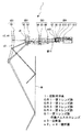
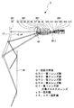
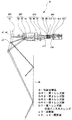
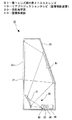
図1は本発明投影光学系の第1の実施の形態である投影光学系1のレンズ構成を示すものである。
FIG. 1 shows a lens configuration of a projection
投影光学系1は、投影側から順に、投影側に凹面を向けた負メニスカスレンズG1で構成された第1レンズ群GR1と、負の屈折力を有する第2レンズ群GR2と、正の屈折力を有する第3レンズ群GR3と、正の屈折力を有する第4レンズ群GR4とが配列されて成り、4群レトロフォーカスタイプのレンズ構成を有する。
The projection
第1レンズ群GR1を構成する負メニスカスレンズG1の凹面(投影側の面)s3は非球面形状を有する反射面とされ、凸面(像側の面)s2、s4は非球面形状の屈折面とされている。第2レンズ群GR2は、投影側から順に、投影側に凸面を向けると共に像側の面が非球面で形成された負メニスカスレンズの第2レンズG2と負レンズの第3レンズG3とが配列されて成る。第3レンズ群GR3は、投影側から順に、正レンズの第4レンズG4と正レンズの第5レンズG5と投影側に凸の正メニスカスレンズの第6レンズG6とが配列されて成る。第4レンズ群GR4は、投影側から順に、投影側の面が非球面で形成された負レンズの第7レンズG7と投影側に凸の負メニスカスレンズの第8レンズG8と正レンズの第9レンズG9と負レンズの第10レンズG10と正レンズの第11レンズG
11と正レンズの第12レンズG12とが配列されて成る。
The concave surface (projection side surface) s3 of the negative meniscus lens G1 constituting the first lens group GR1 is a reflecting surface having an aspherical shape, and convex surfaces (image side surfaces) s2 and s4 are aspherical refractive surfaces. Has been. In the second lens group GR2, in order from the projection side, a second lens G2 of a negative meniscus lens having a convex surface directed toward the projection side and an image side surface formed of an aspheric surface, and a third lens G3 of a negative lens are arranged. It consists of The third lens group GR3 includes, in order from the projection side, a fourth lens G4 as a positive lens, a fifth lens G5 as a positive lens, and a sixth lens G6 as a positive meniscus lens convex on the projection side. The fourth lens group GR4 includes, in order from the projection side, a negative lens seventh lens G7 whose projection side surface is formed as an aspheric surface, a negative meniscus lens eighth lens G8 convex to the projection side, and a ninth positive lens. Lens G9, negative lens tenth lens G10 and positive lens eleventh lens G
11 and a positive twelfth lens G12 are arranged.
この投影光学系1にあっては第2レンズ群GR2と第3レンズ群GR3との間に大きな空気間隙を設けてある。そこで、この空気間隙にプリズム等の光路折り曲げ手段を挿入することが可能である。これによって投影光学系1の奥行寸法を小さくすることができる。
In the projection
上記第1の実施の形態にかかる投影光学系をさらに具体化した数値実施例1を以下の表1乃至表4及び図2に示す。 Numerical Example 1 further embodying the projection optical system according to the first embodiment is shown in the following Tables 1 to 4 and FIG.
まず、表1に各面の曲率半径、面間隔、硝材のd線における屈折率nd及びd線におけるアッベ数νdを、全系の焦点距離「f(all)」、Fナンバー、像高「y′」と共に示す。なお、数値実施例1は投影光学系1をプロジェクターに適用した場合を想定しており、第1レンズG1とスクリーンとの間に位置する背面ミラーMrの反射面を第1面とし、以下、像側に光路を辿って面番号を付してある。従って、第1レンズG1の像側の面は2度光束が通過するので、面番号が2つ(2、4)付してある。なお、第27面乃至第30面は投影光学系1によってスクリーン上に投影される像を形成する像形成部に存在する面であり、参考までに示したものである。また、表中、「INF」は平面を意味し、面番号に続く列に表示した「※」は当該面が非球面であることを意味する。さらに、絞りは面番号「STOP」で示す。
First, Table 1 shows the curvature radius of each surface, the surface spacing, the refractive index nd of the d-line of the glass material, and the Abbe number νd of the d-line, the focal length “f (all)”, F-number, and image height “y” of the entire system. 'Together with'. Numerical Example 1 assumes a case in which the projection
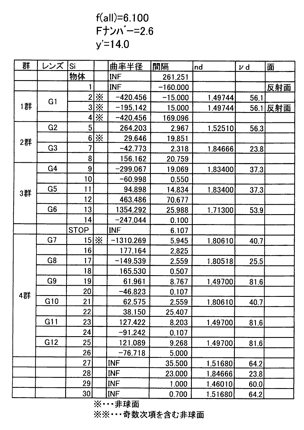
上記投影光学系1において、第1レンズG1の像側の面s2、s4、第1レンズの投影側の面(反射面)s3、第2レンズG2の像側の面s6及び第7レンズG7の投影側の面s15が非球面に形成されている。そこで、表2に数値実施例1における上記各面の4次、6次、8次及び10次の非球面係数A4、A6、A8、A10を円錐定数「K」と共に示す。なお、本明細書において非球面は、数1式によって、また、3次、5次の奇数次項を含む場合は数2式によって、それぞれ定義されるものとする。また、表2中、非球面係数の「E−i」は「10−i」を示すものである。
In the projection
但し、Cは曲率半径の逆数、Hは光軸からの高さ方向の距離 Where C is the reciprocal of the radius of curvature and H is the distance in the height direction from the optical axis.
但し、Cは曲率半径の逆数、Hは光軸からの高さ方向の距離 Where C is the reciprocal of the radius of curvature and H is the distance in the height direction from the optical axis.
数値実施例1における各条件式の元データを表3にまた、各数値を表4に示す。 Table 3 shows original data of each conditional expression in Numerical Example 1, and Table 4 shows each numerical value.
但し、
f(all):全系の焦点距離
φ1:第1レンズ群の屈折力
φ2:第2レンズ群の屈折力
φ12:第1レンズ群と第2レンズ群の合成屈折力
φ3:第3レンズ群の屈折力
φ4:第4レンズ群の屈折力
φ34:第3レンズ群と第4レンズ群の合成屈折力
T23:第2レンズ群と第3レンズ群間の距離
Tmax:負メニスカスレンズの最大像高の光軸に平行な厚み
T0:負メニスカスレンズの軸上厚み
TASr:S3反射面で発生するタンジェンシャル像面湾曲のザイデル収差
TAS2:G2非球面で発生するタンジェンシャル像面湾曲のザイデル収差
SASr:S3反射面で発生するサジタル像面湾曲のザイデル収差
SAS2:G2非球面で発生するサジタル像面湾曲のザイデル収差
However,
f (all): focal length of the entire system φ1: refractive power of the first lens group φ2: refractive power of the second lens group φ12: combined refractive power of the first lens group and the second lens group φ3: of the third lens group Refractive power φ4: Refractive power of the fourth lens group φ34: Combined refractive power of the third lens group and the fourth lens group T23: Distance between the second lens group and the third lens group Tmax: Maximum image height of the negative meniscus lens Thickness parallel to optical axis T0: Thickness on axis of negative meniscus lens TASr: Seidel aberration tangential field curvature generated on reflecting surface TAS2: Seidel aberration SASr: S3 tangential field curvature generated on aspherical surface of G2 Sayder aberration of sagittal field curvature occurring on reflecting surface SAS2: Seidel aberration of sagittal field curvature occurring on G2 aspherical surface
但し、
kr:負メニスカスレンズの反射面の非球面円錐定数
kt:負メニスカスレンズの屈折面の非球面円錐定数
A3R:負メニスカスレンズの反射面の3次非球面係数
A3T:負メニスカスレンズの屈折面の3次非球面係数
A3(2):第2レンズ群非球面の3次非球面係数
ΔP={Θ−(0.6444−0.001689・ν(凸))}×100
Θ=(ng−nF)/(nF−nC)
ν(凸):第4レンズ群の正レンズのd線(587.6nm)のアッベ数
ng:第4レンズ群の正レンズのg線(435.84nm)の屈折率
nF:第4レンズ群の正レンズのF線(486.13nm)の屈折率
nC:第4レンズ群の正レンズのC線(656.28nm)の屈折率
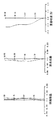
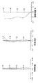
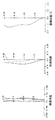
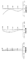
図2に数値実施例1の球面収差、非点収差及び歪曲収差を示す。なお、球面収差図において、実線はg線(波長435.8nm)、破線はd線(波長587.6nm)、一点鎖線はC線(波長656.3nm)におけるそれぞれの収差曲線を示し、非点収差図において、実線はサジタル像面、破線はメリディオナル像面を示すものである。本実施の形態の投影光学系により、球面収差、非点収差及び歪曲収差が良好に補正される。
However,
kr: aspherical conical constant of the reflecting surface of the negative meniscus lens kt: aspherical conic constant of the refracting surface of the negative meniscus lens A3R: third-order aspherical coefficient of the reflecting surface of the negative meniscus lens A3T: 3 of the refracting surface of the negative meniscus lens Second-order aspheric coefficient A3 (2): Third-order aspheric coefficient ΔP = {Θ− (0.6444−0.001689 · ν (convex))} × 100 of the second lens group aspheric surface
Θ = (ng−nF) / (nF−nC)
ν (convex): Abbe number of the d-line (587.6 nm) of the positive lens of the fourth lens group ng: Refractive index nF of the positive line of the fourth lens group (435.84 nm) nF: of the fourth lens group Refractive index nC of the F-line (486.13 nm) of the positive lens: Refractive index of the C-line (656.28 nm) of the positive lens of the fourth lens group FIG. 2 shows the spherical aberration, astigmatism and distortion of the numerical example 1. Indicates. In the spherical aberration diagram, the solid line indicates the respective aberration curves for the g-line (wavelength 435.8 nm), the broken line indicates the d-line (wavelength 587.6 nm), and the alternate long and short dash line indicates the respective aberration curves for the C-line (wavelength 656.3 nm). In the aberration diagrams, a solid line indicates a sagittal image plane, and a broken line indicates a meridional image plane. With the projection optical system of the present embodiment, spherical aberration, astigmatism and distortion are corrected well.
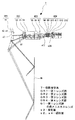
図3は本発明投影光学系の第2の実施の形態である投影光学系2のレンズ構成を示すものである。
FIG. 3 shows the lens configuration of the projection
投影光学系2は、投影側から順に、投影側に凹面を向けた負メニスカスレンズG1で構成された第1レンズ群GR1と、負の屈折力を有する第2レンズ群GR2と、正の屈折力を有する第3レンズ群GR3と、正の屈折力を有する第4レンズ群GR4とが配列されて成り、4群レトロフォーカスタイプのレンズ構成を有する。
The projection
第1レンズ群GR1を構成する負メニスカスレンズG1の凹面(投影側の面)s3は非球面形状を有する反射面とされ、凸面(像側の面)s2、s4は非球面形状の屈折面とされている。第2レンズ群GR2は、投影側から順に、投影側に凸面を向けると共に像側の面が非球面で形成された負メニスカスレンズの第2レンズG2と負レンズの第3レンズG3とが配列されて成る。第3レンズ群GR3は、投影側から順に、投影側に凹面を向けた正メニスカスレンズの第4レンズG4と投影側に凸面を向けた正メニスカスレンズの第5レンズG5と正レンズG6とが配列されて成る。第4レンズ群GR4は、投影側から順に、投影側の面が非球面で形成された負レンズの第7レンズG7と負レンズの第8レンズG8と正レンズの第9レンズG9と投影側に凸面を向けた負メニスカスレンズの第10レンズG10と正レンズの第11レンズG11と正レンズの第12レンズG12とが配列されて成る。 The concave surface (projection side surface) s3 of the negative meniscus lens G1 constituting the first lens group GR1 is a reflecting surface having an aspherical shape, and convex surfaces (image side surfaces) s2 and s4 are aspherical refractive surfaces. Has been. In the second lens group GR2, in order from the projection side, a second lens G2 of a negative meniscus lens having a convex surface directed toward the projection side and an image side surface formed of an aspheric surface, and a third lens G3 of a negative lens are arranged. It consists of In the third lens group GR3, in order from the projection side, a fourth lens G4 of a positive meniscus lens having a concave surface facing the projection side and a fifth lens G5 and a positive lens G6 of a positive meniscus lens having a convex surface facing the projection side are arranged. Made up. The fourth lens group GR4 includes, in order from the projection side, a negative lens seventh lens G7, a negative lens eighth lens G8, a positive lens ninth lens G9, and a projection side. The tenth lens G10, which is a negative meniscus lens having a convex surface, the eleventh lens G11 which is a positive lens, and the twelfth lens G12 which is a positive lens are arranged.
この投影光学系2にあっては第3レンズ群GR3の第5レンズG5と第6レンズG6との間に大きな空気間隙を設けてある。従って、この空気間隙にプリズム等の光路折り曲げ手段を挿入することができる。これによって投影光学系2の奥行寸法を小さくすることができる。
In the projection
上記第2の実施の形態にかかる投影光学系2をさらに具体化した数値実施例2を以下の表5乃至表8及び図4に示す。
Numerical Example 2 further embodying the projection
まず、表5に各面の曲率半径、面間隔、硝材のd線における屈折率nd及びd線におけるアッベ数νdを、全系の焦点距離「f(all)」、Fナンバー、像高「y′」と共に示す。なお、数値実施例2は投影光学系2をプロジェクターに適用した場合を想定しており、第1レンズG1とスクリーンとの間に位置する背面ミラーMrの反射面を第1面とし、以下、像側に光路を辿って面番号を付してある。従って、第1レンズG1の像側の面は2度光束が通過するので、面番号が2つ(2、4)付してある。なお、第27面乃至第30面は投影光学系2によってスクリーン上に投影される像を形成する像形成部に存在する面であり、参考までに示したものである。また、表中、「INF」は平面を意味し、面番号に続く列に表示した「※」は当該面が非球面であることを意味する。さらに、絞りは面番号「STOP」で示す。
First, Table 5 shows the curvature radius of each surface, the surface interval, the refractive index nd of the d-line of the glass material, and the Abbe number νd of the d-line, the focal length “f (all)”, F-number, and image height “y” of the entire system. 'Together with'. Numerical Example 2 assumes a case in which the projection
上記投影光学系2において、第1レンズG1の像側の面s2、s4、第1レンズの投影側の面(反射面)s3、第2レンズG2の像側の面s6及び第7レンズG7の投影側の面s15が非球面に形成されている。そこで、表6に数値実施例2における上記各面の4次、6次、8次及び10次の非球面係数A4、A6、A8、A10を円錐定数「K」と共に示す。
In the projection
数値実施例2における各条件式の元データを表7にまた、各数値を表8に示す。 The original data of each conditional expression in Numerical Example 2 is shown in Table 7, and each numerical value is shown in Table 8.
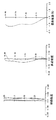
図4に数値実施例2の球面収差、非点収差及び歪曲収差を示す。なお、球面収差図において、実線はg線(波長435.8nm)、破線はd線(波長587.6nm)、一点鎖線はC線(波長656.3nm)におけるそれぞれの収差曲線を示し、非点収差図において、実線はサジタル像面、破線はメリディオナル像面を示すものである。 FIG. 4 shows spherical aberration, astigmatism, and distortion of Numerical Example 2. In the spherical aberration diagram, the solid line indicates the respective aberration curves for the g-line (wavelength 435.8 nm), the broken line indicates the d-line (wavelength 587.6 nm), and the alternate long and short dash line indicates the respective aberration curves for the C-line (wavelength 656.3 nm). In the aberration diagrams, the solid line indicates the sagittal image plane, and the broken line indicates the meridional image plane.
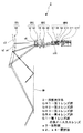
図5は本発明投影光学系の第3の実施の形態である投影光学系3のレンズ構成を示すものである。
FIG. 5 shows the lens configuration of the projection
投影光学系3は、投影側から順に、投影側に凹面を向けた負メニスカスレンズG1で構成された第1レンズ群GR1と、負の屈折力を有する第2レンズ群GR2と、正の屈折力を有する第3レンズ群GR3と、正の屈折力を有する第4レンズ群GR4とが配列されて成り、4群レトロフォーカスタイプのレンズ構成を有する。
The projection
第1レンズ群GR1を構成する負メニスカスレンズG1の凹面(投影側の面)s3は非球面形状を有する反射面とされ、凸面(像側の面)s2、s4は非球面形状の屈折面とされている。第2レンズ群GR2は、投影側から順に、投影側に凸面を向けた負メニスカスレンズの第2レンズG2と投影側に凸面を向けけると共に像側の面が非球面で形成された負メニスカスレンズの第3レンズG3と負レンズの第4レンズG4と投影側に凹面を向けた正メニスカスレンズの第5レンズG5とが配列されて成る。第3レンズ群GR3は、投影側から順に、正レンズの第6レンズG6と投影側に凸面を向けた正メニスカスレンズの第7レンズG7と負レンズの第8レンズG8と正レンズの第9レンズG9とが配列されて成る。第4レンズ群GR4は、投影側から順に、投影側に凸面を向けた正メニスカスレンズの第10レンズG10と負レンズの第11レンズG11と正レンズの第12レンズG12と投影側に凹面を向けた負メニスカスレンズの第13レンズG13と正レンズの第14レンズG14と正レンズの第15レンズG15とが配列されて成る。 The concave surface (projection side surface) s3 of the negative meniscus lens G1 constituting the first lens group GR1 is a reflecting surface having an aspherical shape, and convex surfaces (image side surfaces) s2 and s4 are aspherical refractive surfaces. Has been. The second lens group GR2 includes, in order from the projection side, a second meniscus lens G2 having a convex surface facing the projection side and a negative meniscus lens having a convex surface facing the projection side and an aspheric surface on the image side. The third lens G3, the fourth lens G4 as a negative lens, and the fifth lens G5 as a positive meniscus lens having a concave surface facing the projection side are arranged. The third lens group GR3 includes, in order from the projection side, a sixth lens G6 as a positive lens, a seventh lens G7 as a positive meniscus lens having a convex surface directed toward the projection side, an eighth lens G8 as a negative lens, and a ninth lens as a positive lens. G9 is arranged. In order from the projection side, the fourth lens group GR4 has a tenth lens G10 as a positive meniscus lens having a convex surface directed toward the projection side, an eleventh lens G11 as a negative lens, a twelfth lens G12 as a positive lens, and a concave surface toward the projection side. The negative meniscus lens 13th lens G13, the positive lens 14th lens G14, and the positive lens 15th lens G15 are arranged.
上記第3の実施の形態にかかる投影光学系3をさらに具体化した数値実施例3を以下の表9乃至表12及び図6に示す。
Numerical Example 3 that further embodies the projection
まず、表9に各面の曲率半径、面間隔、硝材のd線における屈折率nd及びd線におけるアッベ数νdを、全系の焦点距離「f(all)」、Fナンバー、像高「y′」と共に示す。なお、数値実施例3は投影光学系3をプロジェクターに適用した場合を想定しており、第1レンズG1とスクリーンとの間に位置する背面ミラーMrの反射面を第1面とし、以下、像側に光路を辿って面番号を付してある。従って、第1レンズG1の像側の面は2度光束が通過するので、面番号が2つ(2、4)付してある。なお、第33面乃至第36面は投影光学系3によってスクリーン上に投影される像を形成する像形成部に存在する面であり、参考までに示したものである。また、表中、「INF」は平面を意味し、面番号に続く列に表示した「※」は当該面が非球面であることを意味する。さらに、絞りは面番号「STOP」で示す。
First, Table 9 shows the curvature radius of each surface, the surface spacing, the refractive index nd of the d-line of the glass material, and the Abbe number νd of the d-line, the focal length “f (all)”, F-number, and image height “y” of the entire system. 'Together with'. Numerical Example 3 assumes a case in which the projection
上記投影光学系3において、第1レンズG1の像側の面s2、s4、第1レンズの投影側の面(反射面)s3、第3レンズG3の像側の面s8が非球面に形成されている。そこで、表10に数値実施例3における上記各面の4次、6次、8次及び10次の非球面係数A4、A6、A8、A10を円錐定数「K」と共に示す。
In the projection
数値実施例3における各条件式の元データを表11にまた、各数値を表12に示す。 The original data of each conditional expression in Numerical Example 3 is shown in Table 11, and each numerical value is shown in Table 12.
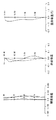
図6に数値実施例3の球面収差、非点収差及び歪曲収差を示す。なお、球面収差図において、実線はg線(波長435.8nm)、破線はd線(波長587.6nm)、一点鎖線はC線(波長656.3nm)におけるそれぞれの収差曲線を示し、非点収差図において、実線はサジタル像面、破線はメリディオナル像面を示すものである。本実施の形態の投影光学系により、球面収差、非点収差及び歪曲収差が良好に補正される。 FIG. 6 shows spherical aberration, astigmatism, and distortion of Numerical Example 3. In the spherical aberration diagram, the solid line indicates the respective aberration curves for the g-line (wavelength 435.8 nm), the broken line indicates the d-line (wavelength 587.6 nm), and the alternate long and short dash line indicates the respective aberration curves for the C-line (wavelength 656.3 nm). In the aberration diagrams, the solid line indicates the sagittal image plane, and the broken line indicates the meridional image plane. With the projection optical system of the present embodiment, spherical aberration, astigmatism and distortion are corrected well.
図7は本発明投影光学系の第4の実施の形態である投影光学系4のレンズ構成を示すものである。
FIG. 7 shows the lens configuration of the projection
投影光学系4は、投影側から順に、投影側に凹面を向けた負メニスカスレンズG1で構成された第1レンズ群GR1と、負の屈折力を有する第2レンズ群GR2と、正の屈折力を有する第3レンズ群GR3と、正の屈折力を有する第4レンズ群GR4とが配列され、さらに、第2レンズ群GR2と第3レンズ群GR3との間にガラスG4が介挿されて成り、4群レトロフォーカスタイプのレンズ構成を有する。
The projection
第1レンズ群GR1を構成する負メニスカスレンズG1の凹面(投影側の面)s3は非球面形状を有する反射面とされ、凸面(像側の面)s2,s4は非球面形状の屈折面とされている。第2レンズ群GR2は、投影側から順に、投影側に凸面を向けると共に像側の面が非球面に形成された負メニスカスレンズの第2レンズG2と負レンズの第3レンズG3とが配列されて成る。第3レンズ群GR3は、投影側から順に、正レンズの第5レンズG5と投影側に凸面を向けた正メニスカスレンズの第6レンズG6と投影側に凸面を向けた正メニスカスレンズの第7レンズG7とが配列されて成る。第4レンズ群GR4は、投影側から順に、投影側に凸面を向けると共に投影側の面が非球面で形成された負メニスカスレンズの第8レンズG8と負レンズの第9レンズG9と正レンズの第10レンズG10と像側の面が非球面で形成された負レンズの第11レンズG11と正レンズの第12レンズG12と正レンズの第13レンズG13とが配列されて成る。 The concave surface (projection side surface) s3 of the negative meniscus lens G1 constituting the first lens group GR1 is a reflecting surface having an aspherical shape, and convex surfaces (image side surfaces) s2 and s4 are aspherical refracting surfaces. Has been. In the second lens group GR2, in order from the projection side, a second lens G2 of a negative meniscus lens having a convex surface directed toward the projection side and an image side surface formed as an aspheric surface, and a third lens G3 of a negative lens are arranged. It consists of The third lens group GR3 includes, in order from the projection side, a fifth lens G5 that is a positive lens, a sixth lens G6 that is a positive meniscus lens having a convex surface facing the projection side, and a seventh lens that is a positive meniscus lens having a convex surface facing the projection side. G7 is arranged. The fourth lens group GR4 includes, in order from the projection side, a negative meniscus lens eighth lens G8, a negative lens ninth lens G9, and a positive lens with a convex surface facing the projection side and a projection side surface formed of an aspheric surface. The tenth lens G10, an eleventh lens G11 that is a negative lens having an aspheric image side surface, a twelfth lens G12 that is a positive lens, and a thirteenth lens G13 that is a positive lens are arranged.
この第4の実施の形態にかかる投影光学系4にあっては、第2レンズ群GR2と第3レンズ群GR3との間にガラスG4が介挿されているので、該ガラスG4に替えてプリズム等の光路折り曲げ手段を介挿することによって光路を折り曲げることができ、これによって、投影光学系4の奥行、すなわち、投影方向の大きさを小さくすることができる。なお、投影光学系の奥行を小さくするための光路折曲用の手段は、プリズムに限られるものではなく、その他の手段、例えば、ミラーのようなものであっても良い。
In the projection
上記第4の実施の形態にかかる投影光学系4をさらに具体化した数値実施例4を以下の表13乃至表16及び図8に示す。
Numerical Example 4 further embodying the projection
まず、表13に各面の曲率半径、面間隔、硝材のd線における屈折率nd及びd線におけるアッベ数νdを、全系の焦点距離「f(all)」、Fナンバー、像高「y′」と共に示す。なお、数値実施例4は投影光学系4をプロジェクターに適用した場合を想定しており、第1レンズG1とスクリーンとの間に位置する背面ミラーMrの反射面を第1面とし、以下、像側に光路を辿って面番号を付してある。従って、第1レンズG1の像側の面は2度光束が通過するので、面番号が2つ(2、4)付してある。なお、第29面乃至第32面は投影光学系4によってスクリーン上に投影される像を形成する像形成部に存在する面であり、参考までに示したものである。また、表中、「INF」は平面を意味し、面番号に続く列に表示した「※」は当該面が非球面であることを意味する。さらに、絞りは
面番号「STOP」で示す。
First, Table 13 shows the curvature radius of each surface, the surface interval, the refractive index nd of the d-line of the glass material, and the Abbe number νd of the d-line, the focal length “f (all)”, F-number, and image height “y” of the entire system. 'Together with'. Numerical Example 4 assumes the case where the projection
上記投影光学系4において、第1レンズG1の像側の面s2、s4、第1レンズの投影側の面(反射面)s3、第2レンズG2の像側の面s6、第8レンズG8の投影側の面s17及び第11レンズG11の像側の面s24が非球面に形成されている。そこで、表14に数値実施例4における上記各面の4次、6次、8次及び10次の非球面係数A4、A6、A8、A10を円錐定数「K」と共に示す。
In the projection
数値実施例4における各条件式の元データを表15にまた、各数値を表16に示す。 Table 15 shows original data of each conditional expression in Numerical Example 4, and Table 16 shows each numerical value.
図8に数値実施例4の球面収差、非点収差及び歪曲収差を示す。なお、球面収差図において、実線はg線(波長435.8nm)、破線はd線(波長587.6nm)、一点鎖線はC線(波長656.3nm)におけるそれぞれの収差曲線を示し、非点収差図において、実線はサジタル像面、破線はメリディオナル像面を示すものである。本実施の形態の投影光学系により、球面収差、非点収差及び歪曲収差が良好に補正される。 FIG. 8 shows spherical aberration, astigmatism, and distortion of Numerical Example 4. In the spherical aberration diagram, the solid line indicates the respective aberration curves for the g-line (wavelength 435.8 nm), the broken line indicates the d-line (wavelength 587.6 nm), and the alternate long and short dash line indicates the respective aberration curves for the C-line (wavelength 656.3 nm). In the aberration diagrams, the solid line indicates the sagittal image plane, and the broken line indicates the meridional image plane. With the projection optical system of the present embodiment, spherical aberration, astigmatism and distortion are corrected well.
図9は本発明投影光学系の第5の実施の形態である投影光学系5のレンズ構成を示すものである。
FIG. 9 shows the lens configuration of the projection
投影光学系5は、投影側から順に、投影側に凹面を向けた負メニスカスレンズG1で構成された第1レンズ群GR1と、負の屈折力を有する第2レンズ群GR2と、正の屈折力を有する第3レンズ群GR3と、正の屈折力を有する第4レンズ群GR4とが配列されて成り、4群レトロフォーカスタイプのレンズ構成を有する。
The projection
第1レンズ群GR1を構成する負メニスカスレンズG1の凹面(投影側の面)s3は非球面形状を有する反射面とされ、凸面(像側の面)s2、s4は非球面形状の屈折面とされている。第2レンズ群GR2は、投影側から順に、投影側に凸面を向けた正メニスカスレンズの第2レンズG2と投影側に凸面を向けけると共に像側の面が非球面で形成された負メニスカスレンズの第3レンズと負レンズの第4レンズG4と投影側に凹面を向けた負メニスカスレンズの第5レンズG5とが配列されて成る。第3レンズ群GR3は、投影側から順に、正レンズの第6レンズG6と投影側に凸面を向けた正メニスカスレンズの第7レンズG7と負レンズの第8レンズG8と正レンズの第9レンズG9とが配列されて成る。第4レンズ群GR4は、投影側から順に、投影側に凹面を向けた負メニスカスレンズの第10レンズG10と投影側に凸面を向けた負メニスカスレンズの第11レンズG11と投影側に凹面を向けた正メニスカスレンズの第12レンズG12と投影側に凹面を向けた負メニスカスレンズの第13レンズG13と正レンズの第14レンズG14と正レンズの第15レンズG15とが配列されて成る。 The concave surface (projection side surface) s3 of the negative meniscus lens G1 constituting the first lens group GR1 is a reflecting surface having an aspherical shape, and convex surfaces (image side surfaces) s2 and s4 are aspherical refractive surfaces. Has been. The second lens group GR2 includes, in order from the projection side, a second lens G2 of a positive meniscus lens having a convex surface facing the projection side, and a negative meniscus lens having a convex surface facing the projection side and an image-side surface formed of an aspherical surface. The third lens, the fourth lens G4 of the negative lens, and the fifth lens G5 of the negative meniscus lens having the concave surface facing the projection side are arranged. The third lens group GR3 includes, in order from the projection side, a sixth lens G6 as a positive lens, a seventh lens G7 as a positive meniscus lens having a convex surface directed toward the projection side, an eighth lens G8 as a negative lens, and a ninth lens as a positive lens. G9 is arranged. The fourth lens group GR4 has, in order from the projection side, a tenth lens G10 of a negative meniscus lens having a concave surface facing the projection side, an eleventh lens G11 of a negative meniscus lens having a convex surface facing the projection side, and a concave surface facing the projection side. A positive meniscus twelfth lens G12, a negative meniscus lens G13 having a concave surface facing the projection side, a positive lens fourteenth lens G14, and a positive lens fifteenth lens G15 are arranged.
上記第5の実施の形態にかかる投影光学系5をさらに具体化した数値実施例5を以下の表17乃至表20及び図10に示す。
Numerical Example 5 further embodying the projection
まず、表17に各面の曲率半径、面間隔、硝材のd線における屈折率nd及びd線におけるアッベ数νdを、全系の焦点距離「f(all)」、Fナンバー、像高「y′」と共に示す。なお、数値実施例5は投影光学系5をプロジェクターに適用した場合を想定しており、第1レンズG1とスクリーンとの間に位置する背面ミラーMrの反射面を第1面とし、以下、像側に光路を辿って面番号を付してある。従って、第1レンズG1の像側の面は2度光束が通過するので、面番号が2つ(2、4)付してある。なお、第33面乃至第36面は投影光学系3によってスクリーン上に投影される像を形成する像形成部に存在する面であり、参考までに示したものである。また、表中、「INF」は平面を意味し、面番号に続く列に表示した「※」は当該面が非球面であることを意味する。さらに、絞りは面番号「STOP」で示す。
First, Table 17 shows the curvature radius of each surface, the surface spacing, the refractive index nd of the d-line of the glass material, and the Abbe number νd of the d-line, the focal length “f (all)”, F-number, and image height “y” of the entire system. 'Together with'. Numerical Example 5 assumes a case where the projection
上記投影光学系5において、第1レンズG1の像側の面s2、s4、第1レンズの投影側の面(反射面)s3、第3レンズG3の像側の面s8が非球面に形成されている。そこで、表18に数値実施例5における上記各面の4次、6次、8次及び10次の非球面係数A4、A6、A8、A10を円錐定数「K」と共に示す。
In the projection
数値実施例5における各条件式の元データを表19に、また、各数値を表20に示す。 Table 19 shows the original data of the conditional expressions in Numerical Example 5 and Table 20 shows the numerical values.
図10に数値実施例5の球面収差、非点収差及び歪曲収差を示す。なお、球面収差図において、実線はg線(波長435.8nm)、破線はd線(波長587.6nm)、一点鎖線はC線(波長656.3nm)におけるそれぞれの収差曲線を示し、非点収差図において、実線はサジタル像面、破線はメリディオナル像面を示すものである。本実施の形態の投影光学系により、球面収差、非点収差及び歪曲収差が良好に補正される。 FIG. 10 shows spherical aberration, astigmatism, and distortion of Numerical Example 5. In the spherical aberration diagram, the solid line indicates the respective aberration curves for the g-line (wavelength 435.8 nm), the broken line indicates the d-line (wavelength 587.6 nm), and the alternate long and short dash line indicates the respective aberration curves for the C-line (wavelength 656.3 nm). In the aberration diagrams, the solid line indicates the sagittal image plane, and the broken line indicates the meridional image plane. With the projection optical system of the present embodiment, spherical aberration, astigmatism and distortion are corrected well.
図11は本発明投影光学系の第6の実施の形態である投影光学系6のレンズ構成を示すものである。
FIG. 11 shows a lens configuration of a projection
投影光学系6は、投影側から順に、投影側に凹面を向けた負メニスカスレンズG1で構成された第1レンズ群GR1と、負の屈折力を有する第2レンズ群GR2と、正の屈折力を有する第3レンズ群GR3と、正の屈折力を有する第4レンズ群GR4とが配列され、さらに、第2レンズ群GR2と第3レンズ群GR3との間にはガラスG4が介挿されており、4群レトロフォーカスタイプのレンズ構成を有する。
The projection
第1レンズ群GR1を構成する負メニスカスレンズG1の凹面(投影側の面)s3は非球面形状を有する反射面とされ、凸面(像側の面)s2、s4は非球面形状の屈折面とされている。第2レンズ群GR2は、投影側から順に、投影側に凸面を向けると共に像側の面が非球面に形成された負メニスカスレンズの第2レンズG2と負レンズの第3レンズG3とが配列されて成る。第3レンズ群GR3は、投影側から順に、正レンズの第5レンズG5と投影側に凸面を向けた正メニスカスレンズの第6レンズG6と投影側に凸面を向けた正メニスカスレンズの第7レンズG7とが配列されて成る。第4レンズ群GR4は、投影側の面が非球面で形成された負レンズの第8レンズG8と負レンズの第9レンズG9と正レンズの第10レンズG10と像側の面が非球面で形成された負レンズの第11レンズ
G11と正レンズの第12レンズG12と正レンズの第13レンズG13とが配列されて成る。
The concave surface (projection side surface) s3 of the negative meniscus lens G1 constituting the first lens group GR1 is a reflecting surface having an aspherical shape, and convex surfaces (image side surfaces) s2 and s4 are aspherical refractive surfaces. Has been. In the second lens group GR2, in order from the projection side, a second lens G2 of a negative meniscus lens having a convex surface directed toward the projection side and an image side surface formed as an aspheric surface, and a third lens G3 of a negative lens are arranged. It consists of The third lens group GR3 includes, in order from the projection side, a fifth lens G5 that is a positive lens, a sixth lens G6 that is a positive meniscus lens having a convex surface facing the projection side, and a seventh lens that is a positive meniscus lens having a convex surface facing the projection side. G7 is arranged. The fourth lens group GR4 has an eighth lens G8 as a negative lens, a ninth lens G9 as a negative lens, a tenth lens G10 as a positive lens, and an image-side surface as an aspheric surface. The formed negative lens 11th lens G11, positive lens 12th lens G12 and positive lens 13th lens G13 are arranged.
この第6の実施の形態にかかる投影光学系6にあっては、第2レンズ群GR2と第3レンズ群GR3との間にガラスG4が介挿されているので、該ガラスG4に替えて光路折り曲げ用のプリズム等を介挿することによって光路を折り曲げることができ、これによって、投影光学系6の奥行、すなわち、投影方向の大きさを小さくすることができる。なお、投影光学系の奥行を小さくするための光路折曲用の手段は、プリズムに限られるものではなく、その他の手段、例えば、ミラーのようなものであっても良い。
In the projection
上記第6の実施の形態にかかる投影光学系6をさらに具体化した数値実施例6を以下の表21乃至表24及び図12に示す。
Numerical Example 6 in which the projection
まず、表21に各面の曲率半径、面間隔、硝材のd線における屈折率nd及びd線におけるアッベ数νdを、全系の焦点距離「f(all)」、Fナンバー、像高「y′」と共に示す。なお、数値実施例6は投影光学系6をプロジェクターに適用した場合を想定しており、第1レンズG1とスクリーンとの間に位置する背面ミラーMrの反射面を第1面とし、以下、像側に光路を辿って面番号を付してある。従って、第1レンズG1の像側の面は2度光束が通過するので、面番号が2つ(2、4)付してある。なお、第29面乃至第32面は投影光学系6によってスクリーン上に投影される像を形成する像形成部に存在する面であり、参考までに示したものである。また、表中、「INF」は平面を意味し、面番号に続く列に表示した「※」は当該面が非球面であることを、「※※」は当該面が奇数次項を含む非球面であることを意味する。さらに、絞りは面番号「STOP」で示す。
First, Table 21 shows the curvature radius of each surface, the surface interval, the refractive index nd of the d-line of the glass material and the Abbe number νd of the d-line, the focal length “f (all)” of the entire system, the F number, and the image height “y”. 'Together with'. Numerical Example 6 assumes the case where the projection
上記投影光学系6において、第1レンズG1の像側の面s2、s4、第1レンズの投影側の面(反射面)s3、第2レンズG2の像側の面s6、第8レンズG8の投影側の面s17及び第11レンズG11の像側の面s24が非球面に形成されている。そこで、表22に数値実施例6における上記各面の3次、4次、5次、6次、8次及び10次の非球面係数A3、A4、A5、A6、A8、A10を円錐定数「K」と共に示す。
In the projection
数値実施例6における各条件式の元データを表23にまた、各数値を表24に示す。 The original data of each conditional expression in Numerical Example 6 is shown in Table 23, and each numerical value is shown in Table 24.
図12に数値実施例6の球面収差、非点収差及び歪曲収差を示す。なお、球面収差図において、実線はg線(波長435.8nm)、破線はd線(波長587.6nm)、一点鎖線はC線(波長656.3nm)におけるそれぞれの収差曲線を示し、非点収差図において、実線はサジタル像面、破線はメリディオナル像面を示すものである。本実施の形態の投影光学系により、球面収差、非点収差及び歪曲収差が良好に補正される。 FIG. 12 shows spherical aberration, astigmatism, and distortion of Numerical Example 6. In the spherical aberration diagram, the solid line indicates the respective aberration curves for the g-line (wavelength 435.8 nm), the broken line indicates the d-line (wavelength 587.6 nm), and the alternate long and short dash line indicates the respective aberration curves for the C-line (wavelength 656.3 nm). In the aberration diagrams, the solid line indicates the sagittal image plane, and the broken line indicates the meridional image plane. With the projection optical system of the present embodiment, spherical aberration, astigmatism and distortion are corrected well.
図13は本発明投影光学系の第7の実施の形態である投影光学系7のレンズ構成を示すものである。
FIG. 13 shows the lens configuration of the projection
投影光学系7は、投影側から順に、投影側に凹面を向けた負メニスカスレンズG1で構成された第1レンズ群GR1と、負の屈折力を有する第2レンズ群GR2と、正の屈折力を有する第3レンズ群GR3と、正の屈折力を有する第4レンズ群GR4とが配列され、さらに、第2レンズ群GR2と第3レンズ群GR3との間にガラスG4が介挿されて成り、4群レトロフォーカスタイプのレンズ構成を有する。
The projection
第1レンズ群GR1を構成する負メニスカスレンズG1の凹面(投影側の面)s3は非球面形状を有する反射面とされ、凸面(像側の面)s2、s4は非球面形状の屈折面とされている。第2レンズ群GR2は、投影側から順に、投影側に凸面を向けると共に像側の面が非球面に形成された負メニスカスレンズの第2レンズG2と負レンズの第3レンズG3とが配列されて成る。第3レンズ群GR3は、投影側から順に、正レンズの第5レンズG5と投影側に凸面を向けた正メニスカスレンズの第6レンズG6と投影側に凸面を向けた正メニスカスレンズの第7レンズG7とが配列されて成る。第4レンズ群GR4は、投影側の面が非球面で形成された負レンズの第8レンズG8と負レンズの第9レンズG9と正レンズの第10レンズG10と像側の面が非球面で形成された負レンズの第11レンズ
G11と正レンズの第12レンズG12と正レンズの第13レンズG13とが配列されて成る。
The concave surface (projection side surface) s3 of the negative meniscus lens G1 constituting the first lens group GR1 is a reflecting surface having an aspherical shape, and convex surfaces (image side surfaces) s2 and s4 are aspherical refractive surfaces. Has been. In the second lens group GR2, in order from the projection side, a second lens G2 of a negative meniscus lens having a convex surface directed toward the projection side and an image side surface formed as an aspheric surface, and a third lens G3 of a negative lens are arranged. It consists of The third lens group GR3 includes, in order from the projection side, a fifth lens G5 that is a positive lens, a sixth lens G6 that is a positive meniscus lens having a convex surface facing the projection side, and a seventh lens that is a positive meniscus lens having a convex surface facing the projection side. G7 is arranged. The fourth lens group GR4 has an eighth lens G8 as a negative lens, a ninth lens G9 as a negative lens, a tenth lens G10 as a positive lens, and an image-side surface as an aspheric surface. The formed negative lens 11th lens G11, positive lens 12th lens G12 and positive lens 13th lens G13 are arranged.
この第7の実施の形態にかかる投影光学系7にあっては、第2レンズ群GR2と第3レンズ群GR3との間にガラスG4が介挿されているので、該ガラスG4に替えて光路折り曲げ用のプリズム等を介挿することによって光路を折り曲げることができ、これによって、投影光学系7の奥行、すなわち、投影方向の大きさを小さくすることができる。なお、投影光学系の奥行を小さくするための光路折曲用の手段は、プリズムに限られるものではなく、その他の手段、例えば、ミラーのようなものであっても良い。
In the projection
上記第7の実施の形態にかかる投影光学系7をさらに具体化した数値実施例7を以下の表25乃至表28及び図14に示す。
Numerical Example 7 further embodying the projection
まず、表25に各面の曲率半径、面間隔、硝材のd線における屈折率nd及びd線におけるアッベ数νdを、全系の焦点距離「f(all)」、Fナンバー、像高「y′」と共に示す。なお、数値実施例7は投影光学系7をプロジェクターに適用した場合を想定しており、第1レンズG1とスクリーンとの間に位置する背面ミラーMrの反射面を第1面とし、以下、像側に光路を辿って面番号を付してある。従って、第1レンズG1の像側の面は2度光束が通過するので、面番号が2つ(2、4)付してある。なお、第29面乃至第32面は投影光学系7によってスクリーン上に投影される像を形成する像形成部に存在する面であり、参考までに示したものである。また、表中、「INF」は平面を意味し、面番号に続く列に表示した「※」は当該面が非球面であることを、「※※」は当該面が奇数次項を含む非球面であることを意味する。さらに、絞りは面番号「STOP」で示す。
First, Table 25 shows the curvature radius of each surface, the surface interval, the refractive index nd of the d-line of the glass material, and the Abbe number νd of the d-line, the focal length “f (all)”, F-number, and image height “y” of the entire system. 'Together with'. Numerical Example 7 assumes a case in which the projection
上記投影光学系7において、第1レンズG1の像側の面s2、s4、第1レンズの投影側の面(反射面)s3、第2レンズG2の像側の面s6、第8レンズG8の投影側の面s17及び第11レンズG11の像側の面s24が非球面に形成されている。そこで、表26に数値実施例7における上記各面の3次、4次、5次、6次、8次及び10次の非球面係数A3、A4、A5、A6、A8、A10を円錐定数「K」と共に示す。
In the projection
数値実施例7における各条件式の元データを表27にまた、各数値を表28に示す。 The original data of each conditional expression in Numerical Example 7 is shown in Table 27, and each numerical value is shown in Table 28.
図14に数値実施例7の球面収差、非点収差及び歪曲収差を示す。なお、球面収差図において、実線はg線(波長435.8nm)、破線はd線(波長587.6nm)、一点鎖線はC線(波長656.3nm)におけるそれぞれの収差曲線を示し、非点収差図において、実線はサジタル像面、破線はメリディオナル像面を示すものである。本実施の形態の投影光学系により、球面収差、非点収差及び歪曲収差が良好に補正される。 FIG. 14 shows spherical aberration, astigmatism, and distortion of Numerical Example 7. In the spherical aberration diagram, the solid line indicates the respective aberration curves for the g-line (wavelength 435.8 nm), the broken line indicates the d-line (wavelength 587.6 nm), and the alternate long and short dash line indicates the respective aberration curves for the C-line (wavelength 656.3 nm). In the aberration diagrams, the solid line indicates the sagittal image plane, and the broken line indicates the meridional image plane. With the projection optical system of the present embodiment, spherical aberration, astigmatism and distortion are corrected well.
図15は本発明投影光学系の第8の実施の形態である投影光学系8のレンズ構成を示すものである。
FIG. 15 shows the lens configuration of the projection
投影光学系8は、投影側から順に、投影側に凹面を向けた負メニスカスレンズG1で構成された第1レンズ群GR1と、負の屈折力を有する第2レンズ群GR2と、正の屈折力を有する第3レンズ群GR3と、正の屈折力を有する第4レンズ群GR4とが配列された、4群レトロフォーカスタイプのレンズ構成を有する。特に、第3レンズ群GR3と第4レンズ群GR4との間に大きな空気間隙をとってある。
The projection
第1レンズ群GR1を構成する負メニスカスレンズG1の凹面(投影側の面)s3は非球面形状を有する反射面とされ、凸面(像側の面)s2、s4は非球面形状の屈折面とされている。第2レンズ群GR2は、投影側から順に、正レンズレンズの第2レンズG2と像側の面が非球面で形成された負レンズの第3レンズG3と負レンズの第4レンズG4が配列されて成る。第3レンズ群GR3は、投影側から順に、投影側に凹面を向けた正メニスカスレンズの第5レンズG5及び投影側に凹面を向けた負メニスカスレンズの第6レンズG6から成る接合レンズと正レンズの第7レンズG7とが配列されて成る。第4レンズ群GR4は、投影側に凸面を向けた正メニスカスレンズの第8レンズG8と投影側に凸面を向けた負メニスカスレンズの第9レンズG9と正レンズの第10レンズG10と投影側に凸面を向けた負メニスカスレンズの第11レンズG11と正レンズの第12レンズG12と正レンズの第13レンズG13とが配列されて成る。 The concave surface (projection side surface) s3 of the negative meniscus lens G1 constituting the first lens group GR1 is a reflecting surface having an aspherical shape, and convex surfaces (image side surfaces) s2 and s4 are aspherical refractive surfaces. Has been. In the second lens group GR2, in order from the projection side, a second lens G2 of a positive lens lens, a third lens G3 of a negative lens having an aspheric surface on the image side, and a fourth lens G4 of a negative lens are arranged. It consists of The third lens group GR3 includes, in order from the projection side, a cemented lens and a positive lens including a fifth lens G5 of a positive meniscus lens having a concave surface facing the projection side and a sixth lens G6 of a negative meniscus lens having a concave surface facing the projection side. The seventh lens G7 is arranged. The fourth lens group GR4 includes a positive meniscus lens eighth lens G8 having a convex surface facing the projection side, a negative meniscus lens ninth lens G9 having a convex surface facing the projection side, and a positive lens tenth lens G10 facing the projection side. An eleventh lens G11 as a negative meniscus lens having a convex surface, a twelfth lens G12 as a positive lens, and a thirteenth lens G13 as a positive lens are arranged.
この撮影光学系8にあっては、第3レンズ群GR3と第4レンズ群GR4との間の大きな空気間隙にプリズム等の光路折り曲げ手段を挿入することが可能であり、これによって投影光学系8の奥行寸法を小さくすることができる。
In this photographic
上記第8の実施の形態にかかる投影光学系8をさらに具体化した数値実施例8を以下の表29乃至表32及び図16に示す。
Numerical Example 8 further embodying the projection
まず、表29に各面の曲率半径、面間隔、硝材のd線における屈折率nd及びd線におけるアッベ数νdを、全系の焦点距離「f(all)」、Fナンバー、像高「y′」と共に示す。なお、数値実施例8は投影光学系8をプロジェクターに適用した場合を想定しており、第1レンズG1とスクリーンとの間に位置する背面ミラーMrの反射面を第1面とし、以下、像側に光路を辿って面番号を付してある。従って、第1レンズG1の像側の面は2度光束が通過するので、面番号が2つ(2、4)付してある。なお、第28面乃至第31面は投影光学系8によってスクリーン上に投影される像を形成する像形成部に存在する面であり、参考までに示したものである。また、表中、「INF」は平面を意味し、面番号に続く列に表示した「※」は当該面が非球面であることを、「※※」は当該面が奇数次項を含む非球面であることを意味する。さらに、絞りは面番号「STOP」で示す。
First, Table 29 shows the curvature radius of each surface, the surface spacing, the refractive index nd of the d-line of the glass material, and the Abbe number νd of the d-line, the focal length “f (all)”, F-number, and image height “y” of the entire system. 'Together with'. Numerical Example 8 assumes a case where the projection
上記投影光学系8において、第1レンズG1の像側の面s2、s4、第1レンズの投影側の面(反射面)s3、第3レンズG3の像側の面s8が非球面に形成されている。そこで、表30に数値実施例8における上記各面の3次、4次、5次、6次、8次及び10次の非球面係数A3、A4、A5、A6、A8、A10を円錐定数「K」と共に示す。
In the projection
数値実施例8における各条件式の元データを表31にまた、各数値を表32に示す。 Table 31 shows original data of each conditional expression in Numerical Example 8, and Table 32 shows each numerical value.
図16に数値実施例8の球面収差、非点収差及び歪曲収差を示す。なお、球面収差図において、実線はg線(波長435.8nm)、破線はd線(波長587.6nm)、一点鎖線はC線(波長656.3nm)におけるそれぞれの収差曲線を示し、非点収差図において、実線はサジタル像面、破線はメリディオナル像面を示すものである。本実施の形態の投影光学系により、球面収差、非点収差及び歪曲収差が良好に補正される。 FIG. 16 shows spherical aberration, astigmatism, and distortion of Numerical Example 8. In the spherical aberration diagram, the solid line indicates the respective aberration curves for the g-line (wavelength 435.8 nm), the broken line indicates the d-line (wavelength 587.6 nm), and the alternate long and short dash line indicates the respective aberration curves for the C-line (wavelength 656.3 nm). In the aberration diagrams, the solid line indicates the sagittal image plane, and the broken line indicates the meridional image plane. With the projection optical system of the present embodiment, spherical aberration, astigmatism and distortion are corrected well.
以上で分かるように、いずれの数値実施例においても、条件式(1)乃至(10)が満足されていて、各収差が良好に補正されると共に、小型化が達成されている。 As can be seen from the above, in any of the numerical examples, the conditional expressions (1) to (10) are satisfied, each aberration is corrected well, and miniaturization is achieved.
なお、上記した各実施の形態では、反射面を除き、入射光線を屈折により偏向させる屈折型レンズ(つまり異なる屈折率を有する媒質同士の界面で偏向が行われるタイプのレンズ)のみが用いられているが、これに限らず、例えば、回折により入射光線を偏向させる回折型レンズ、回折作用と屈折作用との組み合わせで入射光線を偏向させる屈折、回折ハイブリッド型レンズ、入射光線を媒質内の屈折率分布により偏向させる屈折率分布型レンズ等を用いてもよい。 In each of the above-described embodiments, except for the reflecting surface, only a refractive lens that deflects incident light by refraction (that is, a lens that deflects at the interface between media having different refractive indexes) is used. However, the present invention is not limited to this. For example, a diffractive lens that deflects incident light by diffraction, a refraction that deflects incident light by a combination of diffractive action and refracting action, a diffractive hybrid lens, and a refractive index of the incident light in the medium. A gradient index lens or the like deflected by the distribution may be used.
表33に上記各数値実施例における各条件式の元データ及び数値を纏めて示す。 Table 33 summarizes the original data and numerical values of the conditional expressions in the numerical examples.
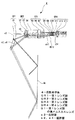
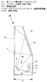
図17及び図18に本発明が像投影装置の実施の形態を示す。なお、図示した実施の形態は、本発明をリアプロジェクションテレビに適用したものである。
17 and 18 show an embodiment of an image projection apparatus according to the present invention. In the illustrated embodiment, the present invention is applied to a rear projection television.
リアプロジェクションテレビ10は筐体20内に必要な部品や部材、装置が配設されて成る。
The
筐体20の前面には下部を除いた部分に大きな開口21が形成され、該開口21を塞ぐように透過型スクリーンScrが配置されている。筐体20内の後方の位置で上記透過型スクリーンScrとほぼ対向した位置に全反射ミラーMrが配置されている。そして、筐体20内の下方部に投影光学系30及び画像形成部40が配置される。そして、画像形成部40で形成された画像がレンズ群G2、G3、G4を介して投影光学系30の第1レンズ群GR1の負メニスカスレンズG1によって全反射ミラーMrに向けて広角反射され、さらに、該全反射ミラーMrによって反射されて透過型スクリーンScrの背面に結像される。従って、画像形成部40で形成された画像が透過型スクリーンScrに拡大投影され、これをスクリーンScrの前方から鑑賞することが出来る。
A
画像形成部40は、投影光学系30によって投影できる画像を形成することが出来るものであれば、どの様なものであっても構わないが、その一例を図18に示す。
The
図18に示した画像形成部40は、R(赤)、G(緑)、B(青)3色の成分に分離された画像信号によって各別に駆動されるR用液晶パネル41R、G用液晶パネル41G、B用液晶パネル41Bの3枚の液晶パネルを備えた3板式フルカラーの画像形成部である。
The
画像形成部40は光源部50を備え、該光源部50によって白色光が平行光束として出射される。光源部50から出射された白色光は全反射ミラー51で反射され、さらに、ダイクロイックミラー42aによってR成分とGB成分に分離され、ダイクロイックミラー42aを透過したGB成分はさらにダイクロイックミラー42bによってG成分とB成分に分離される。ダイクロイックミラー42aで反射されたR成分は全反射ミラー43aでさらに反射されてR用液晶パネル41Rを透過してダイクロイックプリズム44に入射する。ダイクロイックミラー42bで反射されたG成分はG用液晶パネル41Gを透過してダイクロイックプリズム44に入射する。なお、R成分とG成分の光路長は同じになるようにされている。
The
ダイクロイックミラー42bを透過したB成分は全反射ミラー43b、43cによって順次反射されてB用液晶パネル41Bを透過してダイクロイックプリズム44に入射される。なお、このB成分の光路長はR成分、G成分の光路長より長くなるので、光路長調整用のレンズ45a、45aがダイクロイックミラー42aと全反射ミラー43bとの間及び全反射ミラー43bと43cとの間に介挿されている。また、各液晶パネル41R、41G、41Bの入射面側にはコンデンサーレンズ45b、45b、45bが配置されている。
The B component transmitted through the
それぞれの液晶パネル41R、41G、41Bによって空間変調されたR、G、B各成分は色分離フィルタが交差するように配置されたダイクロイックプリズム44によって合成されて一つのフルカラーの画像として出射面44aから出射されて投影光学系30に入射される。
The R, G, and B components spatially modulated by the respective
以上のようにして、フルカラーの画像がスクリーンScrに映し出されることになる。 As described above, a full color image is displayed on the screen Scr.
なお、投影光学系30には上記実施の形態にかかる投影光学系1、2、3、4、5、6、7、8の何れかを使用することができることは勿論である。非球面反射面が小径化されたこの投影光学系を用いることにより、物理的にリアプロジェクションテレビのスクリーン下部(又は上部)を低くすることができる。
Of course, any one of the projection
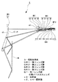
図19はリアプロジェクションテレビの変形例10Aを示すものである。このリアプロジェクションテレビ10Aにあっては、投影光学系30Aの光路上に折り曲げプリズム31が介挿されている点が上記リアプロジェクションテレビ10と異なる。
FIG. 19 shows a
これによって、投影光学系30Aの奥行が小さくなり、これに伴って、リアプロジェクションテレビ10Aの奥行寸法Dも小さくすることができる。図19においては、プリズムにより垂直面内に光路を折り曲げた例を示したが、水平面内に光路を折り曲げるようにしてもよい。
Accordingly, the depth of the projection
画像投影装置の例として、リアプロジェクションテレビの例を記載したが、本発明画像投影装置の適用範囲がリアプロジェクションテレビに限られることを意味するものではない。反射型スクリーンに投影するタイプであるフロントプロジェクター等の画像投影装置等に適用することができることは勿論である。 Although an example of a rear projection television has been described as an example of the image projection device, it does not mean that the application range of the image projection device of the present invention is limited to the rear projection television. Of course, the present invention can be applied to an image projecting apparatus such as a front projector that projects onto a reflective screen.
その他、上記した実施の形態及び数値実施例に示した各部の形状及び構造並びに数値は、何れも本発明を実施するに際して行う具体化のほんの一例を示したものに過ぎず、これらによって本発明の技術的範囲が限定的に解釈されることがあってはならないものである。 In addition, the shapes, structures, and numerical values of the respective parts shown in the above-described embodiments and numerical examples are merely examples of implementation in carrying out the present invention. The technical scope should not be interpreted in a limited way.
画像を投影する装置、特に、広角投影が要望されるにも拘わらず、投影面との間の間隔に制約ある場合に適用して好適である。すなわち、例えば、リアプロジェクションテレビにあっては薄型化が容易である栄、フロントプロジェクターにあっては、狭い部屋のような設置場所に制限がある場合でも大画面で投射することができる。 The present invention is suitable for application to an apparatus for projecting an image, particularly when a wide-angle projection is desired but the distance from the projection surface is limited. That is, for example, a rear projection television can be easily thinned, and a front projector can project a large screen even when the installation location is limited such as a narrow room.
1…投影光学系、2…投影光学系、3…投影光学系、4…投影光学系、5…投影光学系、6…投影光学系、7…投影光学系、8…投影光学系、GR1…第1レンズ群、GR2…第2レンズ群、GR3…第3レンズ群、GR4…第4レンズ群、G1…第1レンズ群の負メニスカスレンズ、s3…反射面、s2、s4…屈折面、10…リアプロジェクションテレビ(画像投影装置)、30…投影光学系、31…プリズム(光路折り曲げ手段)、40…画像形成部、10A…リアプロジェクションテレビ(画像投影装置)、30A…投影光学系
DESCRIPTION OF
Claims (20)
上記第1レンズ群は投影側に凹面を向けると共に該凹面が非球面の反射面とされた負メニスカスレンズで構成される
ことを特徴とする投影光学系。 A retrofocus projection optical system comprising at least a first lens group having a negative refractive power and a second lens group having a negative refractive power arranged in order from the projection side,
The projection optical system according to claim 1, wherein the first lens group includes a negative meniscus lens having a concave surface directed toward the projection side and the concave surface being an aspherical reflecting surface.
(1)0.02<f(all)・|φ1|<0.3
(2)3.0<φ12/φ34<60
(3)−2.0<f(all)・φ12<−0.2
(4)0.1<Tmax/T0<5.0
(5)−30<kr<0
但し、
f(all):全系の焦点距離
φ1:第1レンズ群の屈折力
φ2:第2レンズ群の屈折力
φ12:第1レンズ群と第2レンズ群の合成屈折力
φ34:第3レンズ群と第4レンズ群の合成屈折力
Tmax:負メニスカスレンズの最大像高の光軸に平行な厚み
T0:負メニスカスレンズの軸上厚み
kr:反射面の非球面円錐定数
とする。 A third lens group having a positive refractive power and a fourth lens group having a positive refractive power are arranged in order from the second lens group toward the image side toward the image side, and the following conditional expression (1), The projection optical system according to claim 1, wherein (2), (3), (4), and (5) are satisfied.
(1) 0.02 <f (all) · | φ1 | <0.3
(2) 3.0 <φ12 / φ34 <60
(3) −2.0 <f (all) · φ12 <−0.2
(4) 0.1 <Tmax / T0 <5.0
(5) -30 <kr <0
However,
f (all): focal length of the entire system φ1: refractive power of the first lens group φ2: refractive power of the second lens group φ12: combined refractive power of the first lens group and the second lens group φ34: with the third lens group Synthetic refractive power of the fourth lens group Tmax: thickness parallel to the optical axis of the maximum image height of the negative meniscus lens T0: axial thickness of the negative meniscus lens kr: aspherical cone constant of the reflecting surface.
(6)−15.0<kt<15.0
但し、
kt:屈折面の非球面円錐定数
とする。 2. The projection optical system according to claim 1, wherein a refractive surface of the negative meniscus lens constituting the first lens group is formed as an aspheric surface and satisfies the following conditional expression (6).
(6) -15.0 <kt <15.0
However,
kt: The aspherical conic constant of the refractive surface.
(6)−15.0<kt<15.0
但し、
kt:屈折面の非球面円錐定数
とする。 3. The projection optical system according to claim 2, wherein the negative meniscus lens constituting the first lens group has an aspheric refracting surface and satisfies the following conditional expression (6).
(6) -15.0 <kt <15.0
However,
kt: The aspherical conic constant of the refractive surface.
(7)0.0<A3R<1.0×10⁻¹²
但し、
A3R:負メニスカスレンズの反射面の3次非球面係数
とする。 2. The projection optical system according to claim 1, wherein the aspherical surface of the reflecting surface of the negative meniscus lens of the first lens group includes an odd-order term that satisfies the following conditional expression (7).
(7) 0.0 <A3R <1.0 × 10⁻¹²
However,
A3R: The third aspherical coefficient of the reflecting surface of the negative meniscus lens.
(7)0.0<A3R<1.0×10⁻¹²
但し、
A3R:負メニスカスレンズの反射面の3次非球面係数
とする。 3. The projection optical system according to claim 2, wherein the aspherical surface of the reflecting surface of the negative meniscus lens of the first lens group includes an odd-order term that satisfies the following conditional expression (7).
(7) 0.0 <A3R <1.0 × 10⁻¹²
However,
A3R: The third aspherical coefficient of the reflecting surface of the negative meniscus lens.
(8)0.0<A3T<1.0×10⁻¹²
但し、
A3T:負メニスカスレンズの屈折面の3次非球面係数
とする。 The projection optical system according to claim 1, wherein the aspheric surface of the refracting surface of the negative meniscus lens of the first lens group includes an odd-order term that satisfies the following conditional expression (8).
(8) 0.0 <A3T <1.0 × 10⁻¹²
However,
A3T: A third aspherical coefficient of the refractive surface of the negative meniscus lens.
(8)0.0<A3T<1.0×10⁻¹²
但し、
A3T:負メニスカスレンズの屈折面の3次非球面係数
とする。 3. The projection optical system according to claim 2, wherein the aspherical surface of the refracting surface of the negative meniscus lens of the first lens group includes an odd-order term that satisfies the following conditional expression (8).
(8) 0.0 <A3T <1.0 × 10⁻¹²
However,
A3T: A third aspherical coefficient of the refractive surface of the negative meniscus lens.
ことを特徴とする請求項1に記載の投影光学系。 The projection optical system according to claim 1, wherein at least one of the surfaces of the lenses constituting the second lens group is an aspheric surface.
ことを特徴とする請求項2に記載の投影光学系。 The projection optical system according to claim 2, wherein at least one of the surfaces of the lenses constituting the second lens group is formed as an aspheric surface.
ことを特徴とする請求項1に記載の投影光学系。 The projection optical system according to claim 1, wherein at least one of the surfaces of the lenses constituting the second lens group is formed of an aspherical surface including odd-numbered terms.
ことを特徴とする請求項2に記載の投影光学系。 3. The projection optical system according to claim 2, wherein at least one of the surfaces of the lenses constituting the second lens group is formed of an aspherical surface including odd-numbered terms.
ことを特徴とする請求項1に記載の投影光学系。 The projection optical system according to claim 1, wherein at least one of the surfaces of the lenses constituting the fourth lens group is an aspheric surface.
ことを特徴とする請求項2に記載の投影光学系。 The projection optical system according to claim 2, wherein at least one of the surfaces of the lenses constituting the fourth lens group is an aspheric surface.
(9)0.7<ΔP<6.0
(10)60<ν(凸)<100
但し、
ΔP={Θ−(0.6444−0.001689・ν(凸))}×100
Θ=(ng−nF)/(nF−nC)
ν(凸):正レンズのd線(587.6nm)のアッベ数
ng:正レンズのg線(435.84nm)の屈折率
nF:正レンズのF線(486.13nm)の屈折率
nC:正レンズのC線(656.28nm)の屈折率
とする。 2. The projection optical system according to claim 1, wherein at least one of the positive lenses in the fourth lens group satisfies the following conditional expressions (9) and (10).
(9) 0.7 <ΔP <6.0
(10) 60 <ν (convex) <100
However,
ΔP = {Θ− (0.6444−0.001689 · ν (convex))} × 100
Θ = (ng−nF) / (nF−nC)
ν (convex): Abbe number of d-line (587.6 nm) of positive lens ng: Refractive index of g-line (435.84 nm) of positive lens nF: Refractive index of F-line (486.13 nm) of positive lens nC: The refractive index is the C-line (656.28 nm) of the positive lens.
(9)0.7<ΔP<6.0
(10)60<ν(凸)<100
但し、
ΔP={Θ−(0.6444−0.001689・ν(凸))}×100
Θ=(ng−nF)/(nF−nC)
ν(凸):正レンズのd線(587.6nm)のアッベ数
ng:正レンズのg線(435.84nm)の屈折率
nF:正レンズのF線(486.13nm)の屈折率
nC:正レンズのC線(656.28nm)の屈折率
とする。 The projection optical system according to claim 2, wherein at least one of the positive lenses in the fourth lens group satisfies the following conditional expressions (9) and (10).
(9) 0.7 <ΔP <6.0
(10) 60 <ν (convex) <100
However,
ΔP = {Θ− (0.6444−0.001689 · ν (convex))} × 100
Θ = (ng−nF) / (nF−nC)
ν (convex): Abbe number of d-line (587.6 nm) of positive lens ng: Refractive index of g-line (435.84 nm) of positive lens nF: Refractive index of F-line (486.13 nm) of positive lens nC: The refractive index is the C-line (656.28 nm) of the positive lens.
ことを特徴とする請求項1に記載の投影光学系。 2. The projection optical system according to claim 1, wherein optical path bending means for bending the optical path is interposed between the first lens group and the second lens group or at an appropriate position on the image side from the second lens group.
ことを特徴とする請求項2に記載の投影光学系。 The projection optical system according to claim 2, wherein optical path bending means for bending the optical path is inserted between the first lens group and the second lens group or at an appropriate position on the image side from the second lens group.
上記投影光学系が、少なくとも投影側から順に配列された負の屈折力を有する第1レンズ群と負の屈折力を有する第2レンズ群とを備えたレトロフォーカス型の投影光学系であって、
上記第1レンズ群は投影側に凹面を向けるとともに該凹面が非球面の反射面とされた負メニスカスレンズで構成される
ことを特徴とする画像投影装置。 An image projection apparatus comprising: an image forming unit that forms an image; and a projection optical system that projects an image formed by the image forming unit.
The projection optical system is a retrofocus type projection optical system comprising at least a first lens group having negative refractive power and a second lens group having negative refractive power, which are arranged in order from the projection side,
The first lens group includes a negative meniscus lens having a concave surface directed toward the projection side and the concave surface being an aspherical reflecting surface.
正の屈折力を有する第4レンズ群が配列され、以下の条件式(1)、(2)、(3)、(4)及び(5)を満足することを特徴とする請求項19に記載の画像投影装置。
(1)0.02<f(all)・|φ1|<0.3
(2)3.0<φ12/φ34<20
(3)−2.0<f(all)・φ12<−0.2
(4)0.1<Tmax/T0<5.0
(5)−30<kr<0
但し、
f(all):全系の焦点距離
φ1:第1レンズ群の屈折力
φ2:第2レンズ群の屈折力
φ12:第1レンズ群と第2レンズ群の合成屈折力
φ34:第3レンズ群と第4レンズ群の合成屈折力
Tmax:負メニスカスレンズの最大像高の光軸に平行な厚み
T0:負メニスカスレンズの軸上厚み
kr:反射面の非球面円錐定数
とする。 A third lens group having a positive refractive power and a fourth lens group having a positive refractive power are arranged in order from the second lens group toward the image side toward the image side, and the following conditional expression (1), The image projector according to claim 19, wherein (2), (3), (4), and (5) are satisfied.
(1) 0.02 <f (all) · | φ1 | <0.3
(2) 3.0 <φ12 / φ34 <20
(3) −2.0 <f (all) · φ12 <−0.2
(4) 0.1 <Tmax / T0 <5.0
(5) -30 <kr <0
However,
f (all): focal length of the entire system φ1: refractive power of the first lens group φ2: refractive power of the second lens group φ12: combined refractive power of the first lens group and the second lens group φ34: with the third lens group Synthetic refractive power of the fourth lens group Tmax: thickness parallel to the optical axis of the maximum image height of the negative meniscus lens T0: axial thickness of the negative meniscus lens kr: aspherical cone constant of the reflecting surface.
Priority Applications (1)
| Application Number | Priority Date | Filing Date | Title |
|---|---|---|---|
| JP2005062395A JP2005292813A (en) | 2004-03-12 | 2005-03-07 | Projection optical system and image projection apparatus |
Applications Claiming Priority (2)
| Application Number | Priority Date | Filing Date | Title |
|---|---|---|---|
| JP2004071257 | 2004-03-12 | ||
| JP2005062395A JP2005292813A (en) | 2004-03-12 | 2005-03-07 | Projection optical system and image projection apparatus |
Publications (1)
| Publication Number | Publication Date |
|---|---|
| JP2005292813A true JP2005292813A (en) | 2005-10-20 |
Family
ID=35325743
Family Applications (1)
| Application Number | Title | Priority Date | Filing Date |
|---|---|---|---|
| JP2005062395A Pending JP2005292813A (en) | 2004-03-12 | 2005-03-07 | Projection optical system and image projection apparatus |
Country Status (1)
| Country | Link |
|---|---|
| JP (1) | JP2005292813A (en) |
Cited By (16)
| Publication number | Priority date | Publication date | Assignee | Title |
|---|---|---|---|---|
| JP2007323047A (en) * | 2006-05-01 | 2007-12-13 | Ricoh Co Ltd | Projection optical system and image display apparatus |
| JP2010536057A (en) * | 2007-08-08 | 2010-11-25 | オスラム オプト セミコンダクターズ ゲゼルシャフト ミット ベシュレンクテル ハフツング | Imaging device for projecting an image |
| EP2881776A1 (en) * | 2013-12-05 | 2015-06-10 | Delta Electronics, Inc. | Wide-angle projection optical system |
| WO2017034159A1 (en) * | 2015-08-21 | 2017-03-02 | Samsung Electronics Co., Ltd. | Projection lens system and projection system |
| CN108303788A (en) * | 2018-04-04 | 2018-07-20 | 中山联合光电科技股份有限公司 | A kind of ultrashort out-of-focus projection's optical system of refraction type |
| CN108398846A (en) * | 2018-05-16 | 2018-08-14 | 中山联合光电科技股份有限公司 | A kind of super large projection scope projection optical system |
| US10107996B2 (en) | 2013-12-05 | 2018-10-23 | Delta Electronics, Inc. | Wide-angle projection optical system |
| CN109884780A (en) * | 2019-04-16 | 2019-06-14 | 中山联合光电科技股份有限公司 | A kind of inexpensive, high-resolution ultrashort out-of-focus projection's optical system |
| WO2019151252A1 (en) * | 2018-02-01 | 2019-08-08 | リコーインダストリアルソリューションズ株式会社 | Projection optical system and image display device |
| CN110888288A (en) * | 2018-09-07 | 2020-03-17 | 理光工业解决方案有限公司 | Projection optical system and image projection device |
| CN111123481A (en) * | 2020-01-19 | 2020-05-08 | 中山联合光电科技股份有限公司 | An ultra-short-focus projection lens based on catadioptric optical lens |
| JP2021117278A (en) * | 2020-01-23 | 2021-08-10 | セイコーエプソン株式会社 | Projection optics and projector |
| CN116430652A (en) * | 2021-12-30 | 2023-07-14 | 扬明光学股份有限公司 | projection lens |
| CN117406406A (en) * | 2023-12-04 | 2024-01-16 | 宜宾市极米光电有限公司 | Projection lens |
| CN117420663A (en) * | 2023-12-18 | 2024-01-19 | 苏州高视半导体技术有限公司 | Double telecentric lens for machine vision detection |
| CN120871430A (en) * | 2025-09-25 | 2025-10-31 | 洛阳理工学院 | Infrared, laser and millimeter wave three-mode composite detection seeker optical system |
-
2005
- 2005-03-07 JP JP2005062395A patent/JP2005292813A/en active Pending
Cited By (30)
| Publication number | Priority date | Publication date | Assignee | Title |
|---|---|---|---|---|
| US7529032B2 (en) | 2006-05-01 | 2009-05-05 | Ricoh Company, Ltd. | Projection optical system and image display apparatus |
| US7911704B2 (en) | 2006-05-01 | 2011-03-22 | Ricoh Company, Ltd. | Projection optical system and image display apparatus |
| JP2007323047A (en) * | 2006-05-01 | 2007-12-13 | Ricoh Co Ltd | Projection optical system and image display apparatus |
| JP2010536057A (en) * | 2007-08-08 | 2010-11-25 | オスラム オプト セミコンダクターズ ゲゼルシャフト ミット ベシュレンクテル ハフツング | Imaging device for projecting an image |
| US10107996B2 (en) | 2013-12-05 | 2018-10-23 | Delta Electronics, Inc. | Wide-angle projection optical system |
| EP2881776A1 (en) * | 2013-12-05 | 2015-06-10 | Delta Electronics, Inc. | Wide-angle projection optical system |
| JP2015108797A (en) * | 2013-12-05 | 2015-06-11 | 台達電子工業股▲ふん▼有限公司 | Wide-angle projection optical system |
| WO2017034159A1 (en) * | 2015-08-21 | 2017-03-02 | Samsung Electronics Co., Ltd. | Projection lens system and projection system |
| US10228547B2 (en) | 2015-08-21 | 2019-03-12 | Samsung Electronics Co., Ltd. | Projection lens system and projection system |
| WO2019151252A1 (en) * | 2018-02-01 | 2019-08-08 | リコーインダストリアルソリューションズ株式会社 | Projection optical system and image display device |
| JP6993251B2 (en) | 2018-02-01 | 2022-01-13 | リコーインダストリアルソリューションズ株式会社 | Projection optical system and image display device |
| JP2019133061A (en) * | 2018-02-01 | 2019-08-08 | リコーインダストリアルソリューションズ株式会社 | Projection optical system, and image display device |
| US11868035B2 (en) | 2018-02-01 | 2024-01-09 | Ricoh Industrial Solutions Inc. | Projection optical system and image display device with refractive optical system to form an image on a receiving surface |
| CN111699429A (en) * | 2018-02-01 | 2020-09-22 | 理光工业解决方案有限公司 | Projection optical system and image display device |
| CN111699429B (en) * | 2018-02-01 | 2022-05-17 | 理光工业解决方案有限公司 | Projection optical system and image display device |
| CN108303788A (en) * | 2018-04-04 | 2018-07-20 | 中山联合光电科技股份有限公司 | A kind of ultrashort out-of-focus projection's optical system of refraction type |
| CN108398846A (en) * | 2018-05-16 | 2018-08-14 | 中山联合光电科技股份有限公司 | A kind of super large projection scope projection optical system |
| CN108398846B (en) * | 2018-05-16 | 2024-04-09 | 中山联合光电科技股份有限公司 | A projection optical system with ultra-large projection range |
| CN110888288A (en) * | 2018-09-07 | 2020-03-17 | 理光工业解决方案有限公司 | Projection optical system and image projection device |
| CN110888288B (en) * | 2018-09-07 | 2022-07-15 | 理光工业解决方案有限公司 | Projection optical system and image projection device |
| CN109884780A (en) * | 2019-04-16 | 2019-06-14 | 中山联合光电科技股份有限公司 | A kind of inexpensive, high-resolution ultrashort out-of-focus projection's optical system |
| CN109884780B (en) * | 2019-04-16 | 2024-05-24 | 中山联合光电科技股份有限公司 | Ultra-short-focus projection optical system with low cost and high resolution |
| CN111123481A (en) * | 2020-01-19 | 2020-05-08 | 中山联合光电科技股份有限公司 | An ultra-short-focus projection lens based on catadioptric optical lens |
| JP2021117278A (en) * | 2020-01-23 | 2021-08-10 | セイコーエプソン株式会社 | Projection optics and projector |
| JP7459523B2 (en) | 2020-01-23 | 2024-04-02 | セイコーエプソン株式会社 | Projection optics and projector |
| CN116430652A (en) * | 2021-12-30 | 2023-07-14 | 扬明光学股份有限公司 | projection lens |
| CN117406406A (en) * | 2023-12-04 | 2024-01-16 | 宜宾市极米光电有限公司 | Projection lens |
| CN117420663A (en) * | 2023-12-18 | 2024-01-19 | 苏州高视半导体技术有限公司 | Double telecentric lens for machine vision detection |
| CN117420663B (en) * | 2023-12-18 | 2024-03-12 | 苏州高视半导体技术有限公司 | Double telecentric lens for machine vision detection |
| CN120871430A (en) * | 2025-09-25 | 2025-10-31 | 洛阳理工学院 | Infrared, laser and millimeter wave three-mode composite detection seeker optical system |
Similar Documents
| Publication | Publication Date | Title |
|---|---|---|
| JP4864600B2 (en) | Projection type zoom lens and projection type display device | |
| CN100388040C (en) | Projection optical system and image projection device | |
| US8320048B2 (en) | Projection lens and projection-type display apparatus using the lens | |
| EP3457191B1 (en) | Projection optical system and projector | |
| JP4232269B2 (en) | Projection optical system | |
| US8896929B2 (en) | Projection zoom lens and projection type display device | |
| JP2002107618A (en) | Wide angle projecting lens and projection type image display device using the same | |
| JP6797087B2 (en) | Projection optical system and projection type display device | |
| JP6595405B2 (en) | Imaging optical system, projection display device, and imaging device | |
| US9195034B2 (en) | Lens for projection and projection-type display apparatus | |
| JP6579998B2 (en) | Imaging optical system, projection display device, and imaging device | |
| JP2002350727A (en) | Zoom lens | |
| JP2001324675A (en) | Retrofocus lens and projection display | |
| JP2005292813A (en) | Projection optical system and image projection apparatus | |
| JP2005181993A (en) | Projection lens | |
| JP5026929B2 (en) | Projection lens and projection-type image display device | |
| JP2002244032A (en) | Wide angle projection lens and projection display device | |
| JP6570477B2 (en) | Imaging optical system, projection display device, and imaging device | |
| JP2011154318A (en) | Lens system and optical equipment with the lens system mounted therein | |
| JP2012048016A (en) | Zoom lens for projection and projection image display device | |
| JP2004354405A (en) | Projection lens and projection type image display device | |
| JP4211373B2 (en) | Projection lens and projector provided with the same | |
| JP2008309991A (en) | Projection lens and projection display apparatus using the same | |
| JP2005084456A (en) | Compact retro focus lens | |
| JP2019035871A (en) | Image forming optical system, projection type display device, and imaging device |