JP2005292798A - Transmission type screen and display device - Google Patents
Transmission type screen and display device Download PDFInfo
- Publication number
- JP2005292798A JP2005292798A JP2005040608A JP2005040608A JP2005292798A JP 2005292798 A JP2005292798 A JP 2005292798A JP 2005040608 A JP2005040608 A JP 2005040608A JP 2005040608 A JP2005040608 A JP 2005040608A JP 2005292798 A JP2005292798 A JP 2005292798A
- Authority
- JP
- Japan
- Prior art keywords
- colored layer
- translucent sheet
- light
- display device
- contrast
- Prior art date
- Legal status (The legal status is an assumption and is not a legal conclusion. Google has not performed a legal analysis and makes no representation as to the accuracy of the status listed.)
- Withdrawn
Links
- 230000005540 biological transmission Effects 0.000 title claims description 21
- 239000004925 Acrylic resin Substances 0.000 claims abstract description 4
- 229920000178 Acrylic resin Polymers 0.000 claims abstract description 4
- 229920005668 polycarbonate resin Polymers 0.000 claims abstract description 4
- 239000004431 polycarbonate resin Substances 0.000 claims abstract description 4
- 239000003086 colorant Substances 0.000 claims description 13
- 238000013461 design Methods 0.000 abstract description 6
- 238000002834 transmittance Methods 0.000 description 17
- 239000000975 dye Substances 0.000 description 11
- 239000011347 resin Substances 0.000 description 11
- 229920005989 resin Polymers 0.000 description 11
- 239000003795 chemical substances by application Substances 0.000 description 9
- 239000000463 material Substances 0.000 description 6
- 238000000465 moulding Methods 0.000 description 5
- 230000000052 comparative effect Effects 0.000 description 4
- 238000010586 diagram Methods 0.000 description 4
- 238000005259 measurement Methods 0.000 description 4
- 230000003287 optical effect Effects 0.000 description 4
- 239000011324 bead Substances 0.000 description 3
- 238000000034 method Methods 0.000 description 3
- 238000012986 modification Methods 0.000 description 3
- 230000004048 modification Effects 0.000 description 3
- IYWVGYTUJOMGIO-UHFFFAOYSA-N 2-[(4-amino-9,10-dioxo-3-sulfoanthracen-1-yl)amino]-4-(2-sulfooxyethylsulfonyl)benzoic acid Chemical compound C1=2C(=O)C3=CC=CC=C3C(=O)C=2C(N)=C(S(O)(=O)=O)C=C1NC1=CC(S(=O)(=O)CCOS(O)(=O)=O)=CC=C1C(O)=O IYWVGYTUJOMGIO-UHFFFAOYSA-N 0.000 description 2
- 239000004793 Polystyrene Substances 0.000 description 2
- KXXFHLLUPUAVRY-UHFFFAOYSA-J [Na+].[Na+].[Na+].[Cu++].[O-]C(=O)C1=CC=C(C=C1N=N[C-](N=NC1=C([O-])C(NC2=NC(F)=NC(NCCOCCS(=O)(=O)C=C)=N2)=CC(=C1)S([O-])(=O)=O)C1=CC=CC=C1)S([O-])(=O)=O Chemical compound [Na+].[Na+].[Na+].[Cu++].[O-]C(=O)C1=CC=C(C=C1N=N[C-](N=NC1=C([O-])C(NC2=NC(F)=NC(NCCOCCS(=O)(=O)C=C)=N2)=CC(=C1)S([O-])(=O)=O)C1=CC=CC=C1)S([O-])(=O)=O KXXFHLLUPUAVRY-UHFFFAOYSA-J 0.000 description 2
- HFIYIRIMGZMCPC-UHFFFAOYSA-J chembl1326377 Chemical compound [Na+].[Na+].[Na+].[Na+].[O-]S(=O)(=O)C1=CC2=CC(S([O-])(=O)=O)=C(N=NC=3C=CC(=CC=3)S(=O)(=O)CCOS([O-])(=O)=O)C(O)=C2C(N)=C1N=NC1=CC=C(S(=O)(=O)CCOS([O-])(=O)=O)C=C1 HFIYIRIMGZMCPC-UHFFFAOYSA-J 0.000 description 2
- 230000007423 decrease Effects 0.000 description 2
- 238000007654 immersion Methods 0.000 description 2
- -1 phenylphenol compound Chemical class 0.000 description 2
- 229920003229 poly(methyl methacrylate) Polymers 0.000 description 2
- 239000004926 polymethyl methacrylate Substances 0.000 description 2
- 229920002223 polystyrene Polymers 0.000 description 2
- KUIXZSYWBHSYCN-UHFFFAOYSA-L remazol brilliant blue r Chemical compound [Na+].[Na+].C1=C(S([O-])(=O)=O)C(N)=C2C(=O)C3=CC=CC=C3C(=O)C2=C1NC1=CC=CC(S(=O)(=O)CCOS([O-])(=O)=O)=C1 KUIXZSYWBHSYCN-UHFFFAOYSA-L 0.000 description 2
- 239000002904 solvent Substances 0.000 description 2
- 125000005526 alkyl sulfate group Chemical group 0.000 description 1
- 239000003945 anionic surfactant Substances 0.000 description 1
- 239000006103 coloring component Substances 0.000 description 1
- 229920006037 cross link polymer Polymers 0.000 description 1
- 238000009792 diffusion process Methods 0.000 description 1
- 239000000986 disperse dye Substances 0.000 description 1
- AFOSIXZFDONLBT-UHFFFAOYSA-N divinyl sulfone Chemical group C=CS(=O)(=O)C=C AFOSIXZFDONLBT-UHFFFAOYSA-N 0.000 description 1
- 238000004043 dyeing Methods 0.000 description 1
- 239000011521 glass Substances 0.000 description 1
- 239000004973 liquid crystal related substance Substances 0.000 description 1
- 238000004519 manufacturing process Methods 0.000 description 1
- 239000000113 methacrylic resin Substances 0.000 description 1
- 239000000203 mixture Substances 0.000 description 1
- 239000012466 permeate Substances 0.000 description 1
- 239000000049 pigment Substances 0.000 description 1
- 239000000047 product Substances 0.000 description 1
- 239000000985 reactive dye Substances 0.000 description 1
- 239000000057 synthetic resin Substances 0.000 description 1
- 229920003002 synthetic resin Polymers 0.000 description 1
- 238000010998 test method Methods 0.000 description 1
- XLYOFNOQVPJJNP-UHFFFAOYSA-N water Substances O XLYOFNOQVPJJNP-UHFFFAOYSA-N 0.000 description 1
Images
Classifications
-
- G—PHYSICS
- G03—PHOTOGRAPHY; CINEMATOGRAPHY; ANALOGOUS TECHNIQUES USING WAVES OTHER THAN OPTICAL WAVES; ELECTROGRAPHY; HOLOGRAPHY
- G03B—APPARATUS OR ARRANGEMENTS FOR TAKING PHOTOGRAPHS OR FOR PROJECTING OR VIEWING THEM; APPARATUS OR ARRANGEMENTS EMPLOYING ANALOGOUS TECHNIQUES USING WAVES OTHER THAN OPTICAL WAVES; ACCESSORIES THEREFOR
- G03B21/00—Projectors or projection-type viewers; Accessories therefor
- G03B21/54—Accessories
- G03B21/56—Projection screens
- G03B21/60—Projection screens characterised by the nature of the surface
- G03B21/62—Translucent screens
- G03B21/625—Lenticular translucent screens
Landscapes
- Physics & Mathematics (AREA)
- General Physics & Mathematics (AREA)
- Overhead Projectors And Projection Screens (AREA)
- Projection Apparatus (AREA)
Abstract
【課題】本発明は、単純な設計でコントラストの向上を図ることのできる透過型スクリーン及び表示装置を提供することを目的としている。
【解決手段】入射光側に厚みが2Å以上5μm以下であり、OD値が0.2以上の着色層を設けた透光性シートを備えた透過型スクリーンにより、上記課題を解決する。前記OD値は、さらに0.3〜3.0であることが好ましく、また、前記着色層の厚みはさらに3μm以下であることが好ましい。前記透光性シートは例えばポリカーボネート又はアクリル系樹脂から構成される。
【選択図】 図1
An object of the present invention is to provide a transmissive screen and a display device capable of improving contrast with a simple design.
The above-mentioned problems are solved by a transmissive screen including a translucent sheet provided with a colored layer having an OD value of 0.2 or more and an OD value of 0.2 or more on the incident light side. The OD value is preferably 0.3 to 3.0, and the thickness of the colored layer is preferably 3 μm or less. The translucent sheet is made of, for example, polycarbonate or acrylic resin.
[Selection] Figure 1
Description
本発明は、単純な設計でコントラストの向上を図ることのできる透過型スクリーン及び表示装置に関する。 The present invention relates to a transmissive screen and a display device that can improve contrast with a simple design.
従来より、映像源にCRT(ブラウン管)を用いて、背面より透過型投影スクリーンに映像を投射する背面投射型プロジェクターが知られている。
このような背面投射型プロジェクターでは、コントラストを高めるために、映像光の強度の低下を抑えつつ、外光反射を抑えることが求められる。
2. Description of the Related Art Conventionally, there has been known a rear projection projector that uses a CRT (cathode tube) as an image source and projects an image onto a transmission projection screen from the rear.
In such a rear projection type projector, it is required to suppress external light reflection while suppressing a decrease in intensity of image light in order to increase contrast.
例えば、特許第3335588号(特許文献1)には、このような目的を達成するために、レンチキュラレンズの入光面に着色層を備え、レンチキュラレンズのレンズ部のピッチと着色層の厚さを所定の範囲とした透過型スクリーンが開示されている。また、着色層の厚さをレンチキュラレンズの断面形状との関係で規定した透過型スクリーンが開示されている。
しかしながら、特許文献1に記載の透過型スクリーンでは、レンズピッチとの関係で好適な着色層厚みを定めていた。また、未だコントラストの点で改良の余地があった。
本発明は、単純な設計でコントラストの向上を図ることのできる透過型スクリーン及び表示装置を提供することを目的としている。
However, in the transmissive screen described in
An object of the present invention is to provide a transmissive screen and a display device which can improve contrast with a simple design.
このような状況下、本発明者らは鋭意検討を行った結果、透光性シートの表面形状に限定されずに、着色層の濃度及び厚みを所定範囲とすることで、コントラストに優れた透過型スクリーンを提供し得ることを見出し、本発明を完成するに到ったものである。
上記課題を解決するために、本発明は、入射光側に厚みが2Å(オングストローム)以上5μm以下であり、OD値が0.2以上、好ましくは0.3〜3.0の着色層を設けた透光性シートを備えた透過型スクリーンを提供するものである。
Under such circumstances, as a result of intensive studies, the present inventors are not limited to the surface shape of the light-transmitting sheet, but by setting the concentration and thickness of the colored layer within a predetermined range, transmission with excellent contrast is achieved. The inventors have found that a mold screen can be provided, and have completed the present invention.
In order to solve the above problems, the present invention provides a colored layer having a thickness of 2 mm (angstrom) or more and 5 μm or less and an OD value of 0.2 or more, preferably 0.3 to 3.0 on the incident light side. The present invention provides a transmissive screen including a translucent sheet.
本発明によれば、入射光側に設ける着色層の濃度及び厚みを所定範囲とすることで、コントラストの良好な透過型スクリーンを得ることが可能となる。したがって、種々の形状を有する透光性スクリーンにも容易に適用することができ、着色層の設計に際し、複雑な設計をする必要がない。また、これによれば、入射光側に設ける着色層の光学濃度(OD値)を所定範囲にすることで、コントラストに優れた透過型スクリーンを得ることが可能となる。したがって、種々の形状を有する透光性スクリーンにも容易に適用でき、着色層の設計に際し、複雑な設計をする必要がない。ここで、コントラストとは、光源から発生する光の透過率(白輝度)と外界から入ってくる光(外光)の反射率(黒輝度)の比(白輝度/黒輝度)をいう。 According to the present invention, it is possible to obtain a transmission screen with good contrast by setting the concentration and thickness of the colored layer provided on the incident light side within a predetermined range. Therefore, it can be easily applied to translucent screens having various shapes, and there is no need to make a complicated design when designing the colored layer. Further, according to this, it is possible to obtain a transmissive screen having excellent contrast by setting the optical density (OD value) of the colored layer provided on the incident light side within a predetermined range. Therefore, it can be easily applied to a translucent screen having various shapes, and it is not necessary to design a complicated color layer. Here, the contrast means the ratio (white luminance / black luminance) of the transmittance (white luminance) of light generated from the light source and the reflectance (black luminance) of light (external light) entering from the outside.
上記着色層の厚みが2Å以上3μm以下であることが望ましい。着色層の厚みがかかる範囲にあると、さらにコントラストに優れる。
上記透光性シートがポリカーボネート又はアクリル系樹脂から構成されることが好ましい。このような樹脂によれば、透明度、加工性、機械的強度に優れる。
It is desirable that the colored layer has a thickness of 2 to 3 μm. When the thickness of the colored layer is within such a range, the contrast is further improved.
The translucent sheet is preferably made of polycarbonate or acrylic resin. Such a resin is excellent in transparency, workability, and mechanical strength.
上記着色層に用いられる着色剤が染料であることが好ましい。染料は溶剤に可溶であるので、分散性がよく、着色層濃度を容易に略均一に調整することが可能であり、製造が容易となる。 The colorant used in the colored layer is preferably a dye. Since the dye is soluble in the solvent, the dye has good dispersibility, and the concentration of the colored layer can be easily adjusted to be substantially uniform, which facilitates production.
上記透光性シートが、入射光側に複数の凸状のマイクロレンズが形成されたマイクロレンズアレイシートである場合にも良好なコントラストが得られる。本発明の構成によれば、透光性シートの表面の構造(形状)によらずに良好なコントラストが得られるので、複雑な構造を有するマイクロレンズアレイシートであっても、容易に製造可能である。したがって、任意の方向に視野角制御特性を持たすことが可能で、しかもコントラストが良好な透過型スクリーンが得られる。 Good contrast can also be obtained when the translucent sheet is a microlens array sheet in which a plurality of convex microlenses are formed on the incident light side. According to the configuration of the present invention, a good contrast can be obtained regardless of the structure (shape) of the surface of the translucent sheet. Therefore, even a microlens array sheet having a complicated structure can be easily manufactured. is there. Accordingly, it is possible to obtain a transmissive screen having a viewing angle control characteristic in an arbitrary direction and having a good contrast.
上記透光性シートの両面が略平坦であってもよい。このような場合においても、良好なコントラストが得られる。
本発明の他の態様は、上記いずれかに記載の透過型スクリーンを用いた表示装置を提供するものである。これによれば、コントラストの良好な表示装置を提供し得る。
ここで、表示装置としては、例えば背面透過型表示装置が挙げられる。
Both surfaces of the translucent sheet may be substantially flat. Even in such a case, good contrast can be obtained.
Another aspect of the present invention provides a display device using any one of the transmissive screens described above. According to this, a display device with good contrast can be provided.
Here, as the display device, for example, a rear transmission type display device can be cited.
(第一の実施形態)
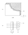
図1は、本発明の透過型スクリーンの一例を説明するための図である。
図1(A)に示すように、透過型スクリーン100は、入射光側からフレネルレンズ60、及び図示しない光源からの光が入射する面に着色層12を備えた透光性シート10を含み構成されている。
(First embodiment)
FIG. 1 is a diagram for explaining an example of a transmission screen of the present invention.
As shown in FIG. 1 (A), a
図1(B)は、光源からの入射光の経路を説明するための図である。一定方向から入射された光20は、フレネルレンズ60で平行光とされた後、着色層12を備えた透光性シート10を通過することにより、拡散され、外方に出射される。
FIG. 1B is a diagram for explaining a path of incident light from the light source. The
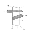
図2は、本発明に用いられる透光性シート10を説明するための図である。
図2に示すように、透光性シート10は、光源(図示せず)からの光20が入射される入射面16に着色層12を備えている。本実施形態では、透光性シート10の表面は、入射面16及び出射面18の双方とも略平坦な面をしている。
FIG. 2 is a diagram for explaining the
As shown in FIG. 2, the translucent sheet |
透光性シート10は、光を透過し得る透光性材料から構成される。このような透光性材料としては、樹脂が機械的強度及び加工性の観点から好ましく用いられる。特に、透明度が高いという観点からは、ポリカーボネート又はアクリル系樹脂(例:ポリメタクリル酸メチル)が好ましい。また、必要に応じて、透光性シート10を形成するための樹脂中に拡散剤を混ぜてもよい。このような拡散剤は、光源からの入射光20を拡散させるためのものであり、例えば、ガラスビーズ、ポリスチレンビーズ、有機架橋ポリマー等を用いることができる。このような拡散剤は、樹脂全体に混入してもよく、また、一部にのみ混入するよう構成してもよい。例えば、出射面18側に拡散剤が多量にあると、外光22が着色層12に達する前に拡散され、反射光として出射されてしまうので、出射面18近傍では、拡散剤濃度を薄くすることが好ましい。したがって、入射面16から出射面18にかけて拡散剤濃度が低くなるよう濃度勾配をつけてもよく、また、入射面16側にのみ拡散層を設けてもよい。拡散剤の濃度は、本発明の目的を達成し得る限り特に限定するものではないが、例えば、樹脂100重量部に対して、0.1〜10重量部の拡散剤が添加される。
The
透光性シート10の厚みは、本発明の課題を達成し得る限り特に限定するものではないが、強度、解像度、視認性等の観点からは、例えば1〜3mmである。また、透光性シート10のHaze(くもり価:Td/Tt、Td:拡散光線透過率、Tt:全光線透過率)も、本発明の課題を達成し得る限り特に限定するものではないが、視野角特性の観点からは、例えば30〜99%程度であることが好ましい。
Although the thickness of the translucent sheet |
着色層12は、例えば染料又は顔料などの着色剤を用いて着色される。特に、着色剤として染料を用いた場合には任意の溶剤に可溶であるので、分散性がよく、着色層濃度を容易に略均一に調整することが可能となる。また、着色剤を溶解した溶液に浸漬し、浸漬時間を調整することにより容易に所望の厚みの着色層12を製造し得るので好ましい。着色剤は、例えば、灰色のような無彩色のもの、又は、図示しない光源の3原色(R(赤)、緑(G)、青(B))のバランスを制御する特定の波長の光を選択的に吸収又は透過し得るものを用いることができる。
The
本願では、分散染料、アニオン界面活性剤、及びキャリアーとしてのフェニルフェノール系化合物を含有する染色液を用いて、合成樹脂を染色する。着色成分として用いる反応染料の例としては、染料便覧(有機合成化学協会編,丸善(1970),880ページ)等に開示されているように(1)クロル・トリアジニル基を持つ染料、(2)ビニル・スルホン基を持つ染料、(3)アルキル硫酸基を持つ染料等を挙げることができる。具体的には、シーアイリアクティブブルー19(C.I.Reactive Blue 19)、シーアイリアクティブブルー27(C.I.Reactive Blue 27)、シーアイリアクティブブルー28(C.I.Reactive Blue 28)、シーアイリアクティブバイオレット5(C.I.Reactive Violet5)、シーアイリアクティブブラック5(C.I.Reactive Black 5)、シーアイリアクティブブラック14(C.I.Reactive Black 14)等が挙げられる。着色層12の厚みは、後述する着色層12の濃度が保持し得る限り、上記着色成分の着色剤が単分子層程度樹脂に混入すれば良好なコントラストを得られる。一般的な着色剤の1分子の大きさは2オングストローム程度なので、着色層12の厚みは、2Å以上5μm以下、好ましくは2オングストローム以上3μm以下であることが望ましい。着色層12の厚さがかかる範囲にあると、入射光20の透過率と外光22の反射率とのバランスに優れる。すなわち、図示しない光源からの入射光20の透過率をあまり低下させることなく、しかも外界から透光性シート10に入射される光(外光)22の反射を抑えることが可能となるので、コントラストが良好となる。
In the present application, the synthetic resin is dyed using a dyeing solution containing a disperse dye, an anionic surfactant, and a phenylphenol compound as a carrier. Examples of reactive dyes used as the coloring component include (1) dyes having a chloro-triazinyl group, as disclosed in Dye Handbook (edited by the Society of Synthetic Organic Chemistry, Maruzen (1970), page 880), (2) Examples thereof include dyes having a vinyl sulfone group and (3) dyes having an alkyl sulfate group. Specifically, CI Reactive Blue 19 (C.I. Reactive Blue 19), C.I. Reactive Blue 27 (C.I. Reactive Blue 27), C.I. Reactive Blue 28 (C.I. Reactive Blue 28), CI Reactive Violet 5 (CI Reactive Violet 5), CI Reactive Black 5 (CI Reactive Black 5), CI Reactive Black 14 (CI Reactive Black 14), and the like. As long as the thickness of the
また、透光性シート10のOD値が0.2以上、好ましくは0.3〜3.0であることが好ましい。これによれば、入射光側に設ける着色層の光学濃度(OD値)を上記範囲にすることで、コントラストに優れた透過型スクリーンを得ることが可能となる。したがって、種々の形状を有する透光性スクリーンにも容易に適用でき、着色層の設計に際し、複雑な設計をする必要がない。また、明るい環境下での明るさとコントラストとのバランスに優れる。
Moreover, it is preferable that OD value of the translucent sheet |
また、さらに、透光性シート10の着色層12より出射面18側の層(基材層14)が、着色がされていないか、若しくはされていても低濃度であることが好ましい。すなわち、着色層12によりほぼ上記OD値が達成されていることが好ましい。基材層14が着色をされていると、入射光20の透過効率が低下する傾向にあり、このようにすることで、光源からの入射光20の透過率をあまり低下させることなく、外光22の反射を低減することが可能となる。
Furthermore, it is preferable that the layer (base material layer 14) on the emission surface 18 side of the
(変形例1)
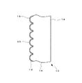
図3は、本発明に用いられる透光性シートの変形例を示す図である。
第一の実施形態において、透光性シート10として表面が略平坦なシートを用いたが、図3に示すように、入射面16に、複数の凸状のマイクロレンズ30が二次元状に形成されたマイクロレンズアレイシートを用いてもよい。マイクロレンズ30の平面形状は、特に限定されず、例えば、略円状、略楕円状であってもよい。
(Modification 1)
FIG. 3 is a view showing a modification of the translucent sheet used in the present invention.
In the first embodiment, a sheet having a substantially flat surface is used as the
このように表面に複数のマイクロレンズ30が形成されている場合でも、着色層12の厚みを上記実施形態で示したような厚みにすることにより、レンズピッチによらずに、良好のコントラストを得ることが可能となる。また、マイクロレンズアレイシートを用いることで、任意の方向に視野角制御特性を持たすことが可能となり、視野角に優れ、しかもコントラストが良好な透過型スクリーン100が得られる。
Even when a plurality of
なお、このようなマイクロレンズアレイシートは、例えば、図1(A)における透光性シート10の代わりに使用することができ、視野角特性に優れた透過型スクリーン100が得られる。
Note that such a microlens array sheet can be used, for example, in place of the
(表示装置)
本発明の透過型スクリーン100は、プロジェクター等の表示装置(電気光学装置)に好適に使用し得る。このような表示装置としては、例えば背面透過型画像表示装置(例:リアプロジェクションTV)等が挙げられる。
(Display device)
The
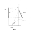
図4は、本発明の表示装置の一例としての背面透過型画像表示装置を説明するための図である。同図に示すように、背面透過型画像表示装置500には、筐体(キャビネット)502内に映像投射装置(例:投射型ブラウン管、液晶等)504が備えられている。筐体502の後方の開口部はミラーカバーで覆われ、このミラーカバー内には反射鏡506が設置されている。筐体502前面には長方形状の開口部が形成されており、透過型スクリーン100が入射光側に着色層12が形成された面16が向くように備えられている。映像投射装置504から投射された映像光508は、反射鏡506で反射された後、透過型スクリーンとしての透光性シート100に投影される。
このように本発明の透過型スクリーンを用いることで、コントラストの良好な表示装置を提供し得る。
FIG. 4 is a view for explaining a rear transmission type image display device as an example of the display device of the present invention. As shown in the figure, the rear transmissive
In this way, by using the transmission screen of the present invention, a display device with good contrast can be provided.
(実施例)
本発明について、実施例を示しながら更に詳しく説明する。
(実施例1)
成形樹脂としてPMMA樹脂(メタクリル樹脂)を用いて、着色層12の厚みが約3μm、シート全体の厚みが1mmの、種々の光学濃度を有し、両面(入射面16及び出射面18)が略平坦な透光性シート10を形成した。ここで、着色層12を形成する着色剤としては、双葉産業株式会社製 商品名:FSPを用いた。着色剤の濃度は、水により希釈して1.48g/Lのものを準備した。また、着色層の厚みは、染色剤に浸漬させる時間を調整することより調整した。その結果、透過率I/I0(I:出射光、I0:入射光)が約30〜95%(32.3%、42.8%、50.6%、66.6%、74.8%、78,4%、86.0%、94.58%)の8つの透光性シート10を得た。この際、全ての透光性シート10の成形時に、成形樹脂100重量部に対し、拡散剤としてポリスチレンビーズ2重量部を、成形樹脂全体に混入した。このときのHazeは全て約70%であった。
このように形成した各透光性シート10について、下記の方法に従い、明室1及び明室2におけるコントラストを測定した。結果を図5及び図6に示す。
(Example)
The present invention will be described in more detail with reference to examples.
(Example 1)
Using PMMA resin (methacrylic resin) as the molding resin, the
About each translucent sheet |
(比較例1)
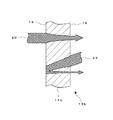
図7は、比較例としての透光性シート10bを説明するための図である。図4において、図1と対応する構成要素については、同一符号を付して説明を省略した。図7に示すように、基材層14b全体に着色を施した透光性シート10bを形成した。形成方法としては、予め成形樹脂全体に着色剤を混入することで、透光性シート10bを形成した。混入する着色剤の濃度を変えることで、3つの透過性シート10bを形成した。得られた透光性シート10の透過率I/I0は、19.1%、37.9%、94.6%であった。
このように形成した各透光性シート10bについて、下記の方法に従い、明室1及び明室2におけるコントラストを測定した。結果を図5及び図6に示す。
(Comparative Example 1)
FIG. 7 is a view for explaining a translucent sheet 10b as a comparative example. In FIG. 4, components corresponding to those in FIG. As shown in FIG. 7, the translucent sheet | seat 10b which colored the whole base material layer 14b was formed. As a forming method, the translucent sheet 10b was formed by previously mixing the colorant into the entire molding resin. Three transparent sheets 10b were formed by changing the concentration of the colorant to be mixed. The transmissivity I / I0 of the obtained
About each translucent sheet | seat 10b formed in this way, the contrast in the
(試験方法)
上記のようにして準備した透光性シートをフレネルレンズと組合わせて透過型スクリーンとし、図4に示すような背面透過型画像表示装置を構成して、明るい部屋(明室)におけるコントラストを測定した。
(Test method)
The translucent sheet prepared as described above is combined with a Fresnel lens to form a transmissive screen, and a rear transmissive image display device as shown in FIG. 4 is configured to measure contrast in a bright room (light room). did.
コントラスト(CNT)として、暗室において413lxの全白光が入射した時の白表示の正面輝度(白輝度)LW(cd/m2)と、明室において光源を全消灯した時の黒表示の正面輝度の増加量(黒輝度増加量)LB(cd/m2)との比LW/LBを求めた。なお、黒輝度増加量は、暗室の黒表示の輝度に対する増加量をいう。 As contrast (CNT), the front luminance (white luminance) LW (cd / m 2) of white display when 413 lx all white light is incident in the dark room and the front luminance of black display when the light source is completely turned off in the bright room. A ratio LW / LB with an increase amount (black luminance increase amount) LB (cd / m 2) was obtained. The black luminance increase amount is an increase amount with respect to the black display luminance in the dark room.
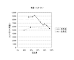
明室は、外光照度が約65lx(明室1)、約185lx(明室2)の部屋で測定した。なお、図5は、明室1における透過率に対するコントラストの測定結果を示すグラフであり、図6は、明室2における透過率に対するコントラストの測定結果を示すグラフである。
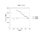
The bright room was measured in a room with an ambient light illuminance of about 65 lx (light room 1) and about 185 lx (light room 2). FIG. 5 is a graph showing a measurement result of contrast with respect to the transmittance in the
図5及び図6に示した実施例1と比較例1のデータの比較から、透過率が約95%よりも低い場合には、同じ透過率では、シート全体に着色されている場合よりも、着色層の厚みを薄くした場合の方がコントラストが向上することが示された。また、シート全体に着色されている場合には、コントラストは透過率によってほとんど変化しないが、本発明のように着色層の厚みを非常に薄くし、かつ着色層の濃度を濃くした場合には、コントラストは透過率に依存して変化することが示された。 From the comparison of the data of Example 1 and Comparative Example 1 shown in FIG. 5 and FIG. 6, when the transmittance is lower than about 95%, the same transmittance is compared with the case where the entire sheet is colored. It was shown that the contrast is improved when the thickness of the colored layer is reduced. Further, when the entire sheet is colored, the contrast hardly changes depending on the transmittance, but when the thickness of the colored layer is very thin and the concentration of the colored layer is increased as in the present invention, It was shown that the contrast varies depending on the transmittance.
また、参考例1のデータより、着色層12の厚みが厚い場合には、コントラストが低下することが示された。
Further, from the data of Reference Example 1, it was shown that when the thickness of the
以上の結果から、コントラストCNTは、透光性シート10の透過率及び着色層12の厚みに依存し、透過率が低くなり(光学濃度が高くなり)、着色層12の厚みが薄くなるほど、向上することが示された。
From the above results, the contrast CNT depends on the transmittance of the
10・・・透過性シート、10b・・・透過性シート、12・・・着色層、14・・・基材層、16・・・入射面、18・・・出射面、20・・・入射光、22・・・外光、30・・・マイクロレンズ、500・・・背面透過型画像表示装置、502・・・筐体、504・・・映像投射装置、506・・・反射鏡、508・・・映像光
DESCRIPTION OF
Claims (8)
A display device using the transmission screen according to claim 1.
Priority Applications (5)
| Application Number | Priority Date | Filing Date | Title |
|---|---|---|---|
| JP2005040608A JP2005292798A (en) | 2004-03-12 | 2005-02-17 | Transmission type screen and display device |
| TW094106308A TWI267682B (en) | 2004-03-12 | 2005-03-02 | Transmissive screen and display device |
| US11/075,156 US20050200954A1 (en) | 2004-03-12 | 2005-03-08 | Transmissive screen and display device |
| MXPA05002646A MXPA05002646A (en) | 2004-03-12 | 2005-03-09 | Transmissive screen and display device. |
| CNA2005100655076A CN1667502A (en) | 2004-03-12 | 2005-03-10 | Transmission type screen and display device |
Applications Claiming Priority (2)
| Application Number | Priority Date | Filing Date | Title |
|---|---|---|---|
| JP2004070223 | 2004-03-12 | ||
| JP2005040608A JP2005292798A (en) | 2004-03-12 | 2005-02-17 | Transmission type screen and display device |
Publications (1)
| Publication Number | Publication Date |
|---|---|
| JP2005292798A true JP2005292798A (en) | 2005-10-20 |
Family
ID=34921772
Family Applications (1)
| Application Number | Title | Priority Date | Filing Date |
|---|---|---|---|
| JP2005040608A Withdrawn JP2005292798A (en) | 2004-03-12 | 2005-02-17 | Transmission type screen and display device |
Country Status (5)
| Country | Link |
|---|---|
| US (1) | US20050200954A1 (en) |
| JP (1) | JP2005292798A (en) |
| CN (1) | CN1667502A (en) |
| MX (1) | MXPA05002646A (en) |
| TW (1) | TWI267682B (en) |
Cited By (1)
| Publication number | Priority date | Publication date | Assignee | Title |
|---|---|---|---|---|
| WO2008096679A1 (en) * | 2007-02-05 | 2008-08-14 | Asahi Kasei Chemicals Corporation | Transmission type screen |
Family Cites Families (3)
| Publication number | Priority date | Publication date | Assignee | Title |
|---|---|---|---|---|
| US5307205A (en) * | 1992-03-20 | 1994-04-26 | Rohm And Haas Company | Bilayer rear projection screens |
| JP2001116917A (en) * | 1999-10-18 | 2001-04-27 | Hitachi Ltd | Image quality improving member and image display device using the same |
| JP2004295090A (en) * | 2003-03-11 | 2004-10-21 | Seiko Instruments Inc | Color liquid crystal display device and manufacturing method therefor, and manufacturing method for color filter substrate |
-
2005
- 2005-02-17 JP JP2005040608A patent/JP2005292798A/en not_active Withdrawn
- 2005-03-02 TW TW094106308A patent/TWI267682B/en not_active IP Right Cessation
- 2005-03-08 US US11/075,156 patent/US20050200954A1/en not_active Abandoned
- 2005-03-09 MX MXPA05002646A patent/MXPA05002646A/en unknown
- 2005-03-10 CN CNA2005100655076A patent/CN1667502A/en active Pending
Cited By (2)
| Publication number | Priority date | Publication date | Assignee | Title |
|---|---|---|---|---|
| WO2008096679A1 (en) * | 2007-02-05 | 2008-08-14 | Asahi Kasei Chemicals Corporation | Transmission type screen |
| JP4777441B2 (en) * | 2007-02-05 | 2011-09-21 | 旭化成ケミカルズ株式会社 | Transmission screen |
Also Published As
| Publication number | Publication date |
|---|---|
| US20050200954A1 (en) | 2005-09-15 |
| TWI267682B (en) | 2006-12-01 |
| CN1667502A (en) | 2005-09-14 |
| MXPA05002646A (en) | 2005-09-14 |
| TW200537206A (en) | 2005-11-16 |
Similar Documents
| Publication | Publication Date | Title |
|---|---|---|
| KR0140051B1 (en) | Transparent screen and manufacturing method | |
| JP3147103B2 (en) | Transmission screen, lenticular sheet, rear projection type image display device using the same, and method of manufacturing sheet-like member | |
| US6322225B1 (en) | Light scattering guiding light source device and liquid crystal display | |
| US5880887A (en) | Lenticular lens sheet, display front plate and transmission type projection screen | |
| US7839568B2 (en) | Bi-stable projection screen | |
| KR19980018702A (en) | LENTICULAR LENS SHEET, DISPLAY FRONT PLATE AND TRANSMISION TYPE PROJECTION SCREEN | |
| JP2018185511A (en) | Display device and method for controlling display device | |
| KR100670960B1 (en) | Translucent Sheets and Screens | |
| JP2010204226A (en) | Transmission type screen | |
| JP2005292798A (en) | Transmission type screen and display device | |
| JP2002006400A (en) | Transmission screen | |
| JP2947160B2 (en) | Transmission screen | |
| JP2001238226A (en) | Front panel for transmissive screen | |
| JPH05273655A (en) | Bead screen | |
| KR100945753B1 (en) | Projection screen | |
| KR100940762B1 (en) | Diffuse sheet for rear projection screen and rear projection screen using same | |
| JPH09133969A (en) | Projection screen | |
| JP3474377B2 (en) | Transmission screen | |
| Ding et al. | 29.1: Invited Paper: A Study on the Micro‐Lens Arrays Combination based Optical Film for Optical Field Optimized Projection Display | |
| JP2907491B2 (en) | Transmissive screen and transmissive screen assembly | |
| JP2002162691A (en) | screen | |
| Wu | P‐63: Design and Fabrication of Wide‐Viewing‐Angle Ambient Light Rejection Front Projection Screen | |
| JP2001005102A (en) | Lenticular lens sheet and transmission screen | |
| JP2003240940A (en) | Resin composition for color filter | |
| JP2000171905A (en) | Transmission screen |
Legal Events
| Date | Code | Title | Description |
|---|---|---|---|
| A977 | Report on retrieval |
Free format text: JAPANESE INTERMEDIATE CODE: A971007 Effective date: 20061228 |
|
| A131 | Notification of reasons for refusal |
Free format text: JAPANESE INTERMEDIATE CODE: A131 Effective date: 20070313 |
|
| A761 | Written withdrawal of application |
Free format text: JAPANESE INTERMEDIATE CODE: A761 Effective date: 20070510 |