JP2005292786A - Fixing device and image forming apparatus using the same - Google Patents
Fixing device and image forming apparatus using the same Download PDFInfo
- Publication number
- JP2005292786A JP2005292786A JP2005016025A JP2005016025A JP2005292786A JP 2005292786 A JP2005292786 A JP 2005292786A JP 2005016025 A JP2005016025 A JP 2005016025A JP 2005016025 A JP2005016025 A JP 2005016025A JP 2005292786 A JP2005292786 A JP 2005292786A
- Authority
- JP
- Japan
- Prior art keywords
- fixing device
- housing
- heating
- roll
- pressure
- Prior art date
- Legal status (The legal status is an assumption and is not a legal conclusion. Google has not performed a legal analysis and makes no representation as to the accuracy of the status listed.)
- Granted
Links
- 238000010438 heat treatment Methods 0.000 claims abstract description 102
- 230000002093 peripheral effect Effects 0.000 claims abstract description 23
- 238000009826 distribution Methods 0.000 claims abstract description 16
- 238000001514 detection method Methods 0.000 claims description 11
- 229920003002 synthetic resin Polymers 0.000 claims description 7
- 239000000057 synthetic resin Substances 0.000 claims description 7
- 230000002411 adverse Effects 0.000 abstract description 6
- 230000002159 abnormal effect Effects 0.000 abstract description 4
- 238000004804 winding Methods 0.000 abstract 1
- 230000000694 effects Effects 0.000 description 7
- 238000003825 pressing Methods 0.000 description 7
- 238000000034 method Methods 0.000 description 6
- 229920005989 resin Polymers 0.000 description 6
- 239000011347 resin Substances 0.000 description 6
- 238000004140 cleaning Methods 0.000 description 4
- 238000012986 modification Methods 0.000 description 4
- 230000004048 modification Effects 0.000 description 4
- 238000012360 testing method Methods 0.000 description 4
- 238000012546 transfer Methods 0.000 description 4
- RNFJDJUURJAICM-UHFFFAOYSA-N 2,2,4,4,6,6-hexaphenoxy-1,3,5-triaza-2$l^{5},4$l^{5},6$l^{5}-triphosphacyclohexa-1,3,5-triene Chemical compound N=1P(OC=2C=CC=CC=2)(OC=2C=CC=CC=2)=NP(OC=2C=CC=CC=2)(OC=2C=CC=CC=2)=NP=1(OC=1C=CC=CC=1)OC1=CC=CC=C1 RNFJDJUURJAICM-UHFFFAOYSA-N 0.000 description 3
- 239000003795 chemical substances by application Substances 0.000 description 3
- 238000012790 confirmation Methods 0.000 description 3
- 239000003063 flame retardant Substances 0.000 description 3
- 239000000463 material Substances 0.000 description 3
- 238000011144 upstream manufacturing Methods 0.000 description 3
- OKTJSMMVPCPJKN-UHFFFAOYSA-N Carbon Chemical compound [C] OKTJSMMVPCPJKN-UHFFFAOYSA-N 0.000 description 2
- 229920000122 acrylonitrile butadiene styrene Polymers 0.000 description 2
- 238000009529 body temperature measurement Methods 0.000 description 2
- 238000005338 heat storage Methods 0.000 description 2
- 239000002184 metal Substances 0.000 description 2
- 229920001721 polyimide Polymers 0.000 description 2
- YCKRFDGAMUMZLT-UHFFFAOYSA-N Fluorine atom Chemical compound [F] YCKRFDGAMUMZLT-UHFFFAOYSA-N 0.000 description 1
- 239000004677 Nylon Substances 0.000 description 1
- 239000004642 Polyimide Substances 0.000 description 1
- 235000010724 Wisteria floribunda Nutrition 0.000 description 1
- 229910052799 carbon Inorganic materials 0.000 description 1
- 239000011248 coating agent Substances 0.000 description 1
- 238000000576 coating method Methods 0.000 description 1
- 230000007547 defect Effects 0.000 description 1
- 238000011161 development Methods 0.000 description 1
- 238000010586 diagram Methods 0.000 description 1
- 230000007613 environmental effect Effects 0.000 description 1
- 239000011737 fluorine Substances 0.000 description 1
- 229910052731 fluorine Inorganic materials 0.000 description 1
- 239000003365 glass fiber Substances 0.000 description 1
- 229910002804 graphite Inorganic materials 0.000 description 1
- 239000010439 graphite Substances 0.000 description 1
- 229920005669 high impact polystyrene Polymers 0.000 description 1
- 239000004797 high-impact polystyrene Substances 0.000 description 1
- 238000005259 measurement Methods 0.000 description 1
- 238000000465 moulding Methods 0.000 description 1
- 229920001778 nylon Polymers 0.000 description 1
- 229920002545 silicone oil Polymers 0.000 description 1
- 229920002050 silicone resin Polymers 0.000 description 1
- 229920002803 thermoplastic polyurethane Polymers 0.000 description 1
Images
Landscapes
- Fixing For Electrophotography (AREA)
- Control Or Security For Electrophotography (AREA)
Abstract
Description
この発明は、複写機、プリンタ、ファクシミリ等の電子写真方式を採用した画像形成装置に用いられる定着装置及びこれを用いた画像形成装置に係り、特に限定するものではないが、トナー中に離型剤を添加して定着装置でのオイルの塗布を行わないオイルレス型や微量のオイルを塗布するオイル微量塗布型の定着方式に特に有用な定着装置及びこれを用いた画像形成装置に関する。
BACKGROUND OF THE
一般に、電子写真方式を採用した画像形成装置においては、互いに圧接しながら回転する加熱部材及び加圧部材と、これら加熱部材及び加圧部材を内部に収容するハウジングとを備え、記録紙等の記録媒体上に転写された未定着トナー像をこれら加熱部材と加圧部材との間で加熱加圧下に定着する定着装置が用いられており、そして、この定着装置については、加熱部材が加熱ロールであって加圧部材が加圧ロールであり、未定着トナー像を担持した記録媒体が上記加熱ロール及び加圧ロールのロールニップ部を加熱加圧下に通過する間に未定着トナー像を記録媒体上に定着させるロールニップ方式や、加熱部材が加熱ロールであって加圧部材が無端状のロール状ベルトからなる加圧ベルトであり、未定着トナー像を担持した記録媒体が上記加熱ロールと加圧ベルトとの間のベルトニップ部を加熱加圧下に通過する間に未定着トナー像を記録媒体上に定着させるベルトニップ方式(特に、フリーベルトニップ方式)(例えば、特開2004-12,682号公報参照)や、加熱部材が押圧体(加熱体又はフィルムガイド)とこの押圧体の一部を覆いながら走行する無端状のロール状ベルトからなる定着フィルム(耐熱性フィルム又は加熱フィルム)とで構成されてこれら押圧体又は定着フィルムのいずれかが通電により発熱すると共に、加圧部材が上記定着フィルムを介して上記押圧体に圧接する加圧ロールからなり、未定着トナー像を担持した記録媒体が上記加熱部材の定着フィルムと加圧ロールとの間のベルトニップ部を加熱加圧下に通過する間に未定着トナー像を記録媒体上に定着させるベルトニップ方式(例えば、特開2003-92,174号公報参照)等の方式が知られている。 In general, an image forming apparatus employing an electrophotographic method includes a heating member and a pressure member that rotate while being pressed against each other, and a housing that accommodates the heating member and the pressure member inside, and records on recording paper or the like. A fixing device for fixing an unfixed toner image transferred on a medium between the heating member and the pressure member under heat and pressure is used, and the fixing member is a heating roll. The pressure member is a pressure roll, and the unfixed toner image is placed on the recording medium while the recording medium carrying the unfixed toner image passes through the heating roll and the roll nip portion of the pressure roll under heat and pressure. A roll nip method for fixing, a pressure belt comprising a heating roller as a heating member and a pressure member as an endless roll belt, and a recording medium carrying an unfixed toner image is the above. A belt nip method (particularly, a free belt nip method) that fixes an unfixed toner image on a recording medium while passing through a belt nip portion between a heat roll and a pressure belt under heat and pressure (for example, Japanese Patent Application Laid-Open No. 2004-2004). -12,682 publication) and a fixing film (heat-resistant film or heating film) comprising a pressing body (heating body or film guide) and an endless roll belt that travels while covering a part of the pressing body. And either of the pressing body or the fixing film generates heat when energized, and the pressing member is composed of a pressing roll that is pressed against the pressing body via the fixing film, and carries an unfixed toner image. A bell for fixing an unfixed toner image on a recording medium while the recording medium passes through a belt nip portion between the fixing film of the heating member and the pressure roll under heat and pressure. A system such as a tonip system (for example, see JP-A-2003-92,174) is known.
ところで、このような定着装置においては、未定着トナー像を加熱溶融させて記録媒体上に定着させるために加熱部材や加圧部材の表面温度が概ね150℃から200数10℃に加熱され、しかも、これら加熱部材や加圧部材がハウジング内に収容された状態で回転するため、ハウジングに形成された記録媒体の排出口と導入口との間にはその排出口側から導入口側に向けて高温のエアフローが不可避的に発生し、このエアフローに伴って定着装置から熱が排出され、この排出された熱が感光体、転写装置、帯電装置、クリーナー装置等の周辺装置に熱的悪影響を及ぼすことがある。 By the way, in such a fixing device, in order to heat and melt an unfixed toner image and fix it on the recording medium, the surface temperature of the heating member or the pressure member is heated from about 150 ° C. to about 200 ° C. to 200 ° C. Since the heating member and the pressure member rotate while being accommodated in the housing, between the discharge port and the introduction port of the recording medium formed in the housing, the discharge port side is directed to the introduction port side. A high-temperature air flow is unavoidably generated, and heat is discharged from the fixing device along with the air flow. The discharged heat has a thermal adverse effect on peripheral devices such as a photosensitive member, a transfer device, a charging device, and a cleaner device. Sometimes.
そこで、従来においては、一般に、定着装置からの排熱が定着装置の周辺装置に悪影響を及ぼすことがないように、画像形成装置に排熱ファンや排熱ダクト等を備えた強制排熱装置を搭載し、定着装置からの排熱を装置外に強制的に排出することが行われている(例えば、特開平11-184,293号公報参照)。 Therefore, conventionally, a forced heat exhaust device provided with a heat exhaust fan, a heat exhaust duct, or the like in the image forming apparatus is generally used so that the heat exhaust from the fixing device does not adversely affect the peripheral devices of the fixing device. It is mounted and the exhaust heat from the fixing device is forcibly discharged outside the device (see, for example, JP-A-11-184,293).
しかしながら、画像形成装置にこのような強制排熱装置を搭載すると、この強制排熱装置が定着装置のハウジング内に生じるエアフローを更に促進することになり、ハウジング内にはより強いエアフローが生じ、定着装置からの排熱が周辺装置に悪影響を及ぼすことは防止されても、加熱部材から放出される定着のための熱が大量に装置外に吐き出され、加熱部材が過度に冷却されてそのエネルギー効率が低下するという別の問題が生じる。 However, when such a forced heat exhaust device is mounted on the image forming apparatus, the forced heat exhaust device further promotes the air flow generated in the housing of the fixing device, and a stronger air flow is generated in the housing. Even if the exhaust heat from the device is prevented from adversely affecting the peripheral device, a large amount of fixing heat released from the heating member is discharged outside the device, and the heating member is excessively cooled to reduce its energy efficiency. Another problem arises that is reduced.
また、画像形成装置に強制排熱装置を搭載すると、この画像形成装置内で発生した熱は、定着装置の加熱部材から発生する熱も含めて、強制排熱装置の排熱ファンや排熱ダクトの吸気口のある方向に集約されて行き、排熱ファンや排熱ダクトの吸気口により近い場所とより遠い場所とで必然的に温度勾配が生じる。同様に、定着装置のハウジング内においても、排熱ファンや排熱ダクトの吸気口により近い場所とより遠い場所とで温度勾配が生じ、加熱部材及び加圧部材の部材長さ方向において排熱量に差が生じ、結果として加熱部材の部材長さ方向において不均一な温度分布が発生する。 When a forced exhaust heat device is mounted on the image forming apparatus, the heat generated in the image forming apparatus includes heat generated from the heating member of the fixing device, including the exhaust heat fan and exhaust heat duct of the forced heat exhaust device. The air intake is concentrated in a certain direction, and a temperature gradient is inevitably generated in a place closer to and farther from the intake of the exhaust heat fan or the exhaust heat duct. Similarly, in the housing of the fixing device, a temperature gradient is generated at a location closer to and farther from the intake port of the exhaust heat fan or exhaust heat duct, and the amount of exhaust heat is increased in the length direction of the heating member and the pressure member. A difference occurs, and as a result, a non-uniform temperature distribution occurs in the length direction of the heating member.
そして、定着装置において、加熱部材及び加圧部材の部材長さ方向に不均一な温度分布が発生すると、加熱部材の温度制御をするための温度センサーが温度勾配の高い側に設置されている場合には、温度勾配の低い側において定着不良が発生する原因になり、反対に、温度勾配の低い側に設置されている場合には、温度勾配の高い側において記録媒体上のトナーが加熱部材に貼り付いてしまう、いわゆるホットオフセットの問題や、加熱部材への記録媒体の貼り付き、異常加熱等が発生する原因になる。 In the fixing device, when a non-uniform temperature distribution occurs in the length direction of the heating member and the pressure member, a temperature sensor for controlling the temperature of the heating member is installed on the higher temperature gradient side. This may cause fixing failure on the low temperature gradient side, and conversely, if it is installed on the low temperature gradient side, the toner on the recording medium is applied to the heating member on the high temperature gradient side. This causes the problem of so-called hot offset, sticking of the recording medium to the heating member, abnormal heating, and the like.
このような定着装置における部材長さ方向の不均一な温度分布が引き起こす種々の問題は、トナー中にワックス等の離型剤を添加することにより、加熱部材及び/又は加圧部材の部材表面に離型剤としてシリコーンオイル等のオイルの供給を行わないオイルレス型定着の場合や、オイルの塗布量を極微量化したオイル微量塗布型定着の場合や、加熱部材が蓄熱量の少ない、あるいは、蓄熱のないクイックフューザー方式を採用した省電力型定着の場合に特に顕在化し、如何にしてこの問題を解決するかがこれらオイルレス型、オイル微量塗布型及び省電力型等の定着方式を採用する上で重要な課題になっている。 Various problems caused by the uneven temperature distribution in the length direction of the member in such a fixing device are caused by adding a release agent such as wax in the toner to the surface of the heating member and / or the pressure member. In the case of oilless fixing that does not supply silicone oil or other oil as a release agent, or in the case of oil minute application type fixing that minimizes the amount of oil applied, the heating member has a small amount of heat storage, or heat storage In the case of power-saving type fixing that uses a quick fuser system without any problem, this oil-less type, a small amount of oil application type, and a power-saving type are used to determine how to solve this problem. It is an important issue.
そこで、本発明者は、このような従来の定着装置におけるエネルギー効率の低下や加熱部材及び/又は加圧部材の部材長さ方向の不均一な温度分布の問題を解決すべく鋭意検討した結果、定着装置のハウジングと加熱部材及び/又は加圧部材との間に、これらハウジング内壁面と加熱部材及び/又は加圧部材の部材表面との間を流れるエアフローの流量を制御するエアフロー制御部を設けることにより、容易に上記の問題を解決できることを見出し、本発明を完成した。 Therefore, the present inventor has intensively studied to solve the problem of the energy efficiency decrease and the uneven temperature distribution in the member length direction of the heating member and / or the pressure member in the conventional fixing device, An air flow control unit is provided between the housing of the fixing device and the heating member and / or the pressure member to control the flow rate of the air flow flowing between the inner wall surface of the housing and the member surface of the heating member and / or the pressure member. Thus, the inventors have found that the above problem can be easily solved, and completed the present invention.
従って、本発明の目的は、ハウジング内でのエアフローの発生を可及的に防止し、これによって周辺装置への熱的悪影響を抑止し若しくは軽減し、第一には過度の強制排熱の必要をなくすと共にエネルギーロスの問題を可及的に解消することができ、また、第二には加熱部材及び/又は加圧部材の部材長さ方向の不均一な温度分布の発生を防止して定着不良、ホットオフセット、記録媒体の貼り付き、異常加熱等の問題が発生するのを防止することができる定着装置及びこの定着装置を搭載した画像形成装置を提供することにある。 Accordingly, it is an object of the present invention to prevent the occurrence of airflow in the housing as much as possible, thereby suppressing or reducing the adverse thermal effects on the peripheral devices, and firstly the need for excessive forced exhaust heat. In addition, the problem of energy loss can be eliminated as much as possible, and secondly, the occurrence of uneven temperature distribution in the length direction of the heating member and / or pressure member is prevented and fixed. An object of the present invention is to provide a fixing device capable of preventing problems such as defects, hot offset, sticking of a recording medium, abnormal heating, and the like, and an image forming apparatus equipped with the fixing device.
すなわち、本発明は、互いに圧接しながら回転する加熱部材及び加圧部材と、これら加熱部材及び加圧部材を内部に収容するハウジングとを備え、記録媒体上に転写された未定着トナー像を上記加熱部材と加圧部材との間で加熱加圧下に定着する定着装置において、上記ハウジングと加熱部材及び/又は加圧部材との間には、これらハウジング内壁面と加熱部材及び/又は加圧部材の部材表面との間を流れるエアフローの流量を制御するエアフロー制御部を設けたことを特徴とする定着装置である。
また、本発明は、このような定着装置を備えた画像形成装置である。
That is, the present invention includes a heating member and a pressure member that rotate while being pressed against each other, and a housing that accommodates the heating member and the pressure member inside, and the unfixed toner image transferred onto the recording medium is stored in the above-described manner. In a fixing device for fixing under heat and pressure between a heating member and a pressure member, between the housing and the heating member and / or the pressure member, the inner wall surface of the housing, the heating member and / or the pressure member. The fixing device is provided with an air flow control unit that controls a flow rate of the air flow flowing between the member surfaces.
Further, the present invention is an image forming apparatus provided with such a fixing device.
本発明において、ハウジング内壁面と加熱部材及び/又は加圧部材の部材表面との間に設けられるエアフロー制御部は、これらハウジング内壁面と部材表面との間の隙間(d)を調整することができればどのような構成であってもよいものであり、ハウジングと一体に形成されていてもよく、また、ハウジングとは別体に形成されてハウジング内壁面に取り付けられていてもよく、好適には以下のようなものを例示することができる。 In the present invention, the air flow controller provided between the inner wall surface of the housing and the member surface of the heating member and / or the pressure member can adjust the gap (d) between the inner wall surface of the housing and the member surface. Any configuration is possible, and it may be formed integrally with the housing, or may be formed separately from the housing and attached to the inner wall surface of the housing. The following can be exemplified.
先ず、エアフロー制御部の第一の例としては、ハウジングと一体に成形され、加熱部材及び/又は加圧部材の部材長さ方向に沿ってその一端側から他端側まで延びる突条形状に形成され、かつ、先端が部材表面に向けて突出してこの部材表面とハウジング内壁面との間の隙間(d)を調整する連続突条を挙げることができ、好ましくはこの連続突条は、ハウジング内壁面から部材表面に向けて突出する突出寸法(p)が部材長さ方向において必要とするエアフローの流量分布に対応して設定される。 First, as a first example of the airflow control unit, it is formed integrally with the housing, and is formed in a ridge shape extending from one end side to the other end side along the member length direction of the heating member and / or the pressure member. And a continuous ridge that protrudes toward the member surface and adjusts the gap (d) between the member surface and the inner wall surface of the housing. Preferably, the continuous ridge is formed in the housing. The projecting dimension (p) projecting from the wall surface toward the member surface is set corresponding to the required air flow distribution in the member length direction.
また、エアフロー制御部の第二の例としては、ハウジングと一体に成形され、加熱部材及び/又は加圧部材の部材長さ方向に沿ってその一端側から他端側まで多数の比較的短い短寸突条が間隔部を形成しつつ直列に並んでおり、かつ、各短寸突条の先端が部材表面に向けて突出する断続突条を挙げることができ、この断続突条については、好ましくは、加熱部材及び/又は加圧部材の部材回転方向に互いに所定の間隔をおいて位置し略平行な複数の縦列を形成する多数の短寸突条で形成されると共に、互いに隣接する一方の列を形成する各短寸突条が他方の列を形成する各間隙部と相対向し、かつ、互いに隣接する一方の列を形成する各間隙部が他方の列を形成する各短寸突条と相対向するように配置され、また、より好ましくは、断続突条は、その各短寸突条の突出寸法(p)及び長さ寸法(l)と各間隔部の間隔寸法(s)とがロール軸方向において必要とするエアフローの流量分布に対応して設定される。 As a second example of the air flow control unit, a plurality of relatively short shorts are formed integrally with the housing and extend from one end side to the other end side along the member length direction of the heating member and / or the pressure member. The intermittent ridges are arranged in series while forming an interval portion, and an intermittent ridge in which the tip of each short ridge protrudes toward the member surface can be mentioned. Is formed of a plurality of short ridges that form a plurality of substantially parallel columns located at predetermined intervals in the member rotation direction of the heating member and / or the pressure member, and one adjacent to each other. Each short ridge in which each short ridge that forms a row is opposite to each gap that forms the other row, and each gap that forms one row adjacent to each other forms the other row And, more preferably, intermittent ridges. The projecting dimension (p) and length dimension (l) of each short ridge and the spacing dimension (s) of each spacing part are set in accordance with the flow distribution of air flow required in the roll axis direction. .
更に、エアフロー制御部の第三の例としては、耐熱性に優れていると共に剛性を有する若しくは弾性に優れた金属板材や合成樹脂板材でハウジングとは別体に形成され、加熱部材及び/又は加圧部材の部材長さ方向に沿ってその一端側から他端側まで連続して又は断続的に延び、かつ、その基端がハウジング内壁面側に取り付けられていると共にその先端が部材表面に向けて突出するエアフロー制御部材を挙げることができ、好ましくは、耐熱性及び弾性に優れた合成樹脂製帯状体で形成され、先端が部材表面に向けて突出してこの部材表面に接触し又は近接する弾性フィルムを挙げることができる。 Further, as a third example of the air flow control unit, a metal plate or a synthetic resin plate that is excellent in heat resistance and has rigidity or elasticity is formed separately from the housing. The pressure member extends continuously or intermittently from one end side to the other end side along the length direction of the pressure member, and its proximal end is attached to the inner wall surface of the housing and its distal end faces the member surface. An airflow control member that protrudes from the surface, preferably a synthetic resin strip that is excellent in heat resistance and elasticity, and has a tip that protrudes toward the surface of the member and comes into contact with or close to the surface of the member. A film can be mentioned.
なお、上記ハウジングとは別体のエアフロー制御部を形成するために用いられる合成樹脂材料としては、優れた耐熱性を有して所望の剛性や弾性を有するものであればよく、例えば、難燃性ABS樹脂、難燃性HIPS樹脂、難燃性PPS樹脂、シリコーン系樹脂、カーボングラファイト樹脂、ウレタン樹脂、ナイロン樹脂、ポリイミド、フッ素系樹脂、ガラス繊維入りPET材、その他の樹脂材料を挙げることができ、コスト的な観点も含めると特に難燃性ABS樹脂が好適に用いられる。 The synthetic resin material used for forming the air flow control unit separate from the housing may be any material having excellent heat resistance and desired rigidity and elasticity. Absorptive ABS resin, flame retardant HIPS resin, flame retardant PPS resin, silicone resin, carbon graphite resin, urethane resin, nylon resin, polyimide, fluorine resin, PET containing glass fiber, and other resin materials In view of cost, flame retardant ABS resin is particularly preferably used.
本発明において、ハウジングは、その成形上、好ましくは加熱部材側の加熱部材側ハウジングと加圧部材側の加圧部材側ハウジングとに分割されているのがよく、これによってハウジング内壁面にエアフロー制御部を構成する連続突条や断続突条を一体に成形したり、別体に形成されたエアフロー制御部を構成する弾性フィルムを取り付けることが容易になる。 In the present invention, the housing is preferably divided into a heating member side housing on the heating member side and a pressure member side housing on the pressure member side in terms of molding, whereby air flow control is performed on the inner wall surface of the housing. It becomes easy to integrally form continuous ridges and intermittent ridges constituting the part, or attach an elastic film constituting the airflow control part formed separately.
また、本発明において、エアフロー制御部にはその部材長さ方向の適宜位置に、好ましくは端部に温度検知装置の熱検知部が収容される凹部を形成し、この凹部内に熱検知部を収容して加熱部材の温度測定を行うのがよく、これによって温度測定の際にエアフローによる外乱影響を可及的に抑制することができる。 Further, in the present invention, the air flow control unit is formed with a recess for accommodating the heat detection unit of the temperature detection device at an appropriate position in the length direction of the member, preferably at the end, and the heat detection unit is provided in the recess. It is preferable that the temperature of the heating member is accommodated, and thereby the influence of disturbance due to airflow can be suppressed as much as possible during temperature measurement.
本発明によれば、ハウジングと加熱部材及び/又は加圧部材との間には、これらハウジング内壁面と加熱部材及び/又は加圧部材の部材表面との間を流れるエアフローの流量を制御するエアフロー制御部が設けられているので、ハウジング内でのエアフローの発生を可及的に防止することができ、これによって周辺装置への熱的悪影響を抑止若しくは軽減できるだけでなく、過度の強制排熱の必要をなくすと共にエネルギーロスの問題を可及的に解消することができる。 According to the present invention, between the housing and the heating member and / or the pressure member, the air flow that controls the flow rate of the air flow that flows between the inner wall surface of the housing and the member surface of the heating member and / or the pressure member. Since the control unit is provided, it is possible to prevent the occurrence of air flow in the housing as much as possible, thereby not only suppressing or reducing the adverse thermal effects on the peripheral devices, but also excessive forced exhaust heat. The need for energy loss can be eliminated as much as possible.
また、本発明によれば、このエアフロー制御部には部材長さ方向において必要とするエアフローの流量分布に対応した設計を容易に施すことができ、これによって部材長さ方向の不均一な温度分布の発生を防止して定着不良、ホットオフセット、記録媒体の貼り付き、異常加熱等の問題が発生するのを容易に防止することができる。 In addition, according to the present invention, the airflow control unit can be easily designed to correspond to the required airflow flow rate distribution in the member length direction, thereby providing a nonuniform temperature distribution in the member length direction. Therefore, it is possible to easily prevent problems such as fixing failure, hot offset, sticking of a recording medium, and abnormal heating.
以下、添付図面に示す実施例に基づいて、本発明の好適な実施の形態を具体的に説明する。 Hereinafter, preferred embodiments of the present invention will be specifically described based on examples shown in the accompanying drawings.
〔実施例1〕
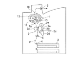
図1に、本発明の実施例1に係る定着装置1が搭載された画像形成装置が示されている。この画像形成装置においては、上記定着装置1の記録用紙(記録媒体:搬送経路として図示)Pの搬送経路上流側(図1中では定着装置1の下方)に、矢印方向に回転する潜像担持体としての感光体ドラム2aと、この感光体ドラム2aの表面を一様に帯電させる帯電ロール2bと、帯電した感光体ドラム2aの表面に画像情報(複写機であれば原稿の読み取り画像、プリンタであれば外部機器から入力される入力画像等)に応じて露光して静電潜像を形成する露光装置2cと、感光体ドラム2aの表面に形成された静電潜像を現像剤により可視化する現像装置2dと、給紙トレイ3から搬送ロール4により搬送されてレジストロール5により所定のタイミングで供給される記録用紙Pに上記現像装置2dで可視化された未定着トナー像を転写する転写ロール2eと、未定着トナー像が転写された後に感光体ドラム2aの表面に残留した残留トナー等を除去して清掃するクリーニング装置2fとを備えた画像形成部2が配設されており、上記定着装置1で未定着トナー像が定着されて定着画像を有する記録用紙Pは定着装置1の搬送経路下流側(図1中では定着装置1の上方)の搬送ロール6から装置外部に排出されるようになっている。
[Example 1]
FIG. 1 shows an image forming apparatus equipped with a fixing
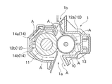
また、この実施例1の画像形成装置において、上記定着装置1は、図1及び図2に示されているように、互いに圧接しながら回転する加熱ロール(加熱部材)10及び加圧ロール(加圧部材)11と、これら加熱ロール10及び加圧ロール11を内部に収容するハウジング12とを備えたロールニップ方式のものであり、その背面側に図示外の排熱ファンを備えた強制排熱装置が搭載されており、搭載された定着装置1に関してみると、この定着装置1は、そのロール軸方向(部材長さ方向)のリア側が比較的高温になる傾向にあり、また、そのロール軸方向のフロント側が比較的低温になる傾向にある。
Further, in the image forming apparatus of Example 1, the fixing
そして、上記定着装置1においては、図1及び図2に示されているように、転写ロール2eにより転写された未定着トナー像を有する記録用紙Pが定着装置1の用紙導入口1aから装置内に導入されて用紙排出口1bから装置外に排出されるまでの間に、未定着トナー像が上記加熱ロール10と加圧ロール11との間で加熱加圧下に記録用紙P上に定着されるようになっており、また、上記ハウジング12は加熱ロール10側の加熱ロール側ハウジング12aと加圧ロール11側の加圧ロール側ハウジング12bとに分割されている。そして、この定着装置1においては、そのハウジング12内で加熱ロール10及び加圧ロール11が回転することにより、図2に矢印Aで示すように、用紙排出口1bから装置内に入ってこの装置内で加熱され、比較的高温になって用紙導入口1aから装置外に出て行くエアフローが生じる傾向を示す。
In the
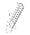
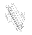
この実施例1において、上記加熱ロール側ハウジング12aには、図2、図3及び図4に示されているように、この加熱ロール側ハウジング12aと一体に成形され、加熱ロール10のロール軸方向に沿ってその一端側から他端側まで連続して延びる突条形状に形成され、かつ、先端がロール外周面(部材表面)に向けて突出し、加熱ロール10のロール外周面と加熱ロール側ハウジング12aのハウジング内壁面との間の隙間(d)を調整し、これによってこれらロール外周面とハウジング内壁面との間を流れるエアフローの流量を制御する連続突条(エアフロー制御部)13が設けられている。
In the first embodiment, the heating
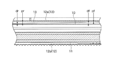
そして、上記連続突条13は、図3及び図4に示されているように、画像形成装置に搭載された際に装置の背面側となるリア側(比較的高温側)位置から装置の前面側となるフロント側(比較的低温側)位置に向けて、ハウジング内壁面からロール外周面に向けて突出する突出寸法(p)がリア側突出寸法(pr)からフロント側突出寸法(pf)へと連続的に小さくなり、これに応じてロール外周面とハウジング内壁面との間の隙間(d)がリア側隙間寸法(dr)からフロント側隙間寸法(df)へと連続的に大きくなり、排熱ファンのある装置の背面側に向けて流れるエアフローを、比較的大きなリア側突出寸法(pr)の連続突条13のリア側で比較的多量に受けて比較的小さなフロント側突出寸法(pf)の連続突条13のフロント側へとロール軸方向に導き、これによってロール軸方向において温度の均一化を図る上で必要なエアフローの流量分布を達成するようになっている。
Then, as shown in FIGS. 3 and 4, the
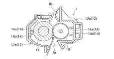
また、この実施例1において、上記加圧ロール側ハウジング12bには、図2及び図5に示されているように、この加圧ロール側ハウジング12bと一体に成形され、加圧ロール11のロール軸方向に沿ってその一端側から他端側まで多数の比較的短い短寸突条15が間隔部16を形成しつつ直列に並んで縦列を形成し、かつ、各短寸突条15の先端がロール外周面に向けて突出し、加圧ロール11のロール外周面と加圧ロール側ハウジング12bのハウジング内壁面との間を流れるエアフローの流量を制御する断続突条(エアフロー制御部)14が設けられている。
In the first embodiment, the pressure
そして、この実施例1では、上記断続突条14は、ロール円周方向(部材回転方向)に所定の間隔を置いて位置する互いに略平行な上下2つの縦列14a,14bを形成し、また、互いに隣接する一方の列を形成する各短寸突条15aが他方の列を形成する各間隙部16bと相対向し、かつ、互いに隣接する一方の列を形成する各間隙部16aが他方の列を形成する各短寸突条15bと相対向するように配置されている。
And in this Example 1, the said
この加圧ロール側ハウジング12b側にエアフロー制御部として設けられる断続突条14においては、図5に示されているように、加圧ロール11のロール外周面に沿って流れるエアフローは、上流側に位置する断続突条14の縦列14aにおいて各短寸突条15aの間の各間隙部16aを矢印A方向に流れ、次いでこの矢印A方向のエアフローは下流側に位置する断続突条14の縦列14bにおいて各短寸突条15bに衝突し、この各短寸突条15bにおいて左右に分かれてそれぞれ矢印B方向に流れ、これら矢印B方向に流れるエアフローは各間隙部16bにおいて互いに衝突して混合されながらこれら各間隙部16bを更に下流へと流れていく。
In the
従って、この加圧ロール側ハウジング12b側の断続突条14においても、各短寸突条15の突出寸法(p)及び長さ寸法(l)と各間隔部16の間隔寸法(s)とを、ロール軸方向においてエアフローがその全体としてリア側(比較的高温側)からフロント側(比較的低温側)に向けて流れるように設計することにより、ロール軸方向において温度の均一化を図る上で必要なエアフローの流量分布を達成することができる。
Therefore, also in the
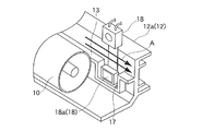
更に、この実施例1の定着装置1においては、図6に示されているように、加熱ロール側ハウジング12にエアフロー制御部として形成された連続突条13には、この加熱ロール10の温度を測定するための温度検知装置18が取り付けられる位置に、この連続突条13の上面から所定の長さ寸法及び深さ寸法で窪んだ凹部17が形成されており、この凹部17内に上記温度検知装置18の熱検知部18aが収容され、連続突条13の上面に沿って流れるエアフローがこの熱検知部18aに直接には当たらないようになっており、これによって熱検知部18aが加熱ロール10の表面温度を正確に検知できるようになっている。
Further, in the
〔実施例2及び効果確認試験〕
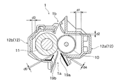
図7に本発明の実施例2に係る定着装置21が示されている。この実施例2の定着装置21は、その基本的な構成は上記実施例1の場合と同じであるが、上記実施例1の場合とは異なり、エアフロー制御部が、耐熱性及び剛性に優れたポリイミドフィルムからなる合成樹脂製帯状体でハウジング12とは別体に形成され、基端側が加熱ロール側ハウジング12aの用紙導入口1a付近に取り付けられていると共にその先端が加熱ロール10のロール外周面に向けてその回転方向の接線方向に同じ突出寸法(p)で突出する加熱ロール側エアフロー制御部材19aと、基端側が加圧ロール側ハウジング12bの用紙導入口1a付近に取り付けられていると共にその先端が加圧ロール11のロール外周面に向けてその回転方向の接線方向に同じ突出寸法(p)で突出する加圧ロール側エアフロー制御部材19bとで構成されている。
[Example 2 and effect confirmation test]
FIG. 7 shows a fixing device 21 according to
そして、この実施例2の定着装置21を画像形成装置(富士ゼロックス株式会社製の機種DocuPrint405/505:用紙搬送速度242mm/s,生産性50枚(A4)/分)に搭載し、定着装置21に取り付けたエアフロー制御部(加熱ロール側エアフロー制御部材19a及び加圧ロール側エアフロー制御部材19b)の効果を調べた。
Then, the fixing device 21 of Example 2 is mounted on an image forming apparatus (model DocuPrint405 / 505 manufactured by Fuji Xerox Co., Ltd .: paper conveyance speed 242 mm / s, productivity 50 sheets (A4) / min). The effects of the air flow control units (the heating roll side air
なお、この実施例2の定着装置21において、加熱ロール10のロール径は25mmφで、加圧ロール11のロール径は30mmφで、加熱ロール10の制御温度(用紙走行時)は195℃であり、また、加熱ロール側ハウジング12a、加圧ロール側ハウジング12b、加熱ロール側エアフロー制御部材19a及び加圧ロール側エアフロー制御部材19bの各先端と加熱ロール10及び加圧ロール11のロール外周面との間の隙間寸法(d)は、図7に示すように、d1=7.5mm、d2=3.0mm、d3=5.0mm、d4=1.0mm、及びd5=1.0mmであった。また、この定着装置21を搭載した画像形成装置が設置された場所におけるテスト時の環境温度は25℃であった。
In the fixing device 21 of Example 2, the roll diameter of the
この状態でA4サイズの普通紙を横方向同一原稿で約1時間連続してプリントし、装置内温度が一定になった時点で、定着装置21の記録用紙Pの搬送経路の上流側に位置する画像形成部2のクリーニング装置2f周辺(図1参照)において、その定着装置21ロール軸方向のリア側、中央、及びフロクト側の3箇所でそれぞれ温度測定を行った。
結果は、それぞれリア側が56.7℃、中央が50.2℃、及びフロクト側が46.4℃であった。
In this state, A4 size plain paper is continuously printed on the same document in the horizontal direction for about one hour, and when the internal temperature becomes constant, the fixing device 21 is positioned upstream of the conveyance path of the recording paper P. In the vicinity of the
The results were 56.7 ° C. on the rear side, 50.2 ° C. on the center, and 46.4 ° C. on the float side, respectively.
また、比較のために、エアフロー制御部としての上記加熱ロール側エアフロー制御部材19a及び加圧ロール側エアフロー制御部材19bを取り外し、上記の効果確認試験と全く同様にして定着装置21ロール軸方向のリア側、中央、及びフロクト側の3箇所でそれぞれ温度測定を行った。
結果は、それぞれリア側が68.4℃、中央が64.9℃、及びフロクト側が49.2℃であった。
For comparison, the heating roll side air
As a result, the rear side was 68.4 ° C., the center was 64.9 ° C., and the fruct side was 49.2 ° C.
上記の効果確認試験の結果から明らかなように、上記エアフロー制御部を取り付けた場合には、エアフロー制御部を設けない場合と比較して、リア側で11.7℃、中央で14.7℃、及びフロクト側で2.8℃の温度降下が認められ、また、リア側とフロクト側との間の温度差については、エアフロー制御部を取り付けた場合が10.3℃であってエアフロー制御部を設けない場合が19.2℃であり、8.9℃の温度差改善が確認された。 As is clear from the results of the above effect confirmation test, when the air flow control unit is attached, the rear side is 11.7 ° C. and the center is 14.7 ° C., compared to the case where the air flow control unit is not provided. , And a temperature drop of 2.8 ° C. was observed on the fruct side, and the temperature difference between the rear side and the fruct side was 10.3 ° C. when the air flow control unit was attached. In the case where no is provided, the temperature difference was 19.2 ° C., and an improvement in temperature difference of 8.9 ° C. was confirmed.
〔エアフロー制御部の変形例〕
図8〜図10に本発明の定着装置におけるエアフロー制御部の変形例が示されている。なお、これらの変形例を示す図8〜図10において、上記実施例1の定着装置1の場合と共通する部分には同じ符号が付されている。
[Modified example of air flow control unit]
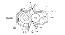
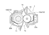
8 to 10 show modified examples of the airflow control unit in the fixing device of the present invention. In FIGS. 8 to 10 showing these modified examples, the same reference numerals are given to portions common to the case of the fixing
図8に示す定着装置1におけるエアフロー制御部は、上記実施例1の場合とは異なり、加熱ロール側ハウジング12a及び加圧ロール側ハウジング12bの両方に、加圧ロール側ハウジング12b側に設けたと同様の上下2列の縦列14a,14bからなる断続突条14からなるものである。
The airflow control unit in the
また、図9に示す定着装置1におけるエアフロー制御部は、上記実施例1の場合とは異なり、金属板材で断面L字状に形成され、先端が加熱ロール10及び加圧ロール11のロール外周面に向けて突出するエアフロー制御部材20a,20bと、耐熱性及び弾性に優れた合成樹脂製帯状体で形成され、先端が加熱ロール10及び加圧ロール11のロール外周面に向けて突出してこのロール外周面に接触する弾性フィルム21a,21bとからなり、加熱ロール側ハウジング12a及び加圧ロール側ハウジング12bのハウジング内壁面の略中央部と用紙導入口1a付近とにそれぞれ取り付けられている。
The air flow control unit in the
更に、図10に示す定着装置1におけるエアフロー制御部は、上記実施例1の場合とは異なり、耐熱性及び弾性に優れた合成樹脂製帯状体で断面略く字状に形成され、先端が加熱ロール10及び加圧ロール11のロール外周面に向けて突出しこれらのロール外周面にその回転方向の接線方向から接触する弾性フィルム22a,22bとからなり、加熱ロール側ハウジング12a及び加圧ロール側ハウジング12bのハウジング内壁面にそれぞれ取り付けられている。
Further, the air flow control unit in the
上記図8〜図10に示すいずれのエアフロー制御部の場合も、断続突条14の各短寸突条の突出寸法(p)及び長さ寸法(l)と各間隔部の間隔寸法(s)とを調整したり(図8の場合)、エアフロー制御部材20a,20bの突出寸法(p)や弾性フィルム21a,21bの先端接触強さを調整したり(図9の場合)、あるいは、弾性フィルム22a,22bの接触強さを調整する(図10の場合)ことにより、ロール軸方向においてエアフローの流量分布を制御し、均一化することができる。
In any of the air flow control units shown in FIGS. 8 to 10, the projecting dimension (p) and length dimension (l) of each short ridge of the
なお、上記の各実施例及び変形例においては、定着装置として加熱ロール及び加圧ロールを備えたロールニップ方式のものを採用しているが、本発明は、このロールニップ方式の定着装置に限られるものではなく、加熱側をベルト状加熱部材にしたものや、加圧側をベルト状加圧部材にしたもの等のいわゆるベルト定着装置にも適用できることは勿論である。 In each of the above-described embodiments and modifications, a roll nip type having a heating roll and a pressure roll is employed as the fixing device, but the present invention is limited to this roll nip type fixing device. Of course, the present invention can be applied to a so-called belt fixing device such as a belt-shaped heating member on the heating side or a belt-shaped pressing member on the pressure side.
本発明の定着装置及びこれを用いた画像形成装置は、従来の定着装置においてこれまで問題になっていたエネルギー効率の低下や加熱部材及び/又は加圧部材の部材長さ方向の不均一な温度分布の問題を一挙に解決できるものであり、特に定着温度のより正確な制御を要求されるオイルレス型、オイル微量塗布型及び省電力型等の定着方式を採用する定着装置及び画像形成装置に有用である。 The fixing device of the present invention and the image forming apparatus using the fixing device have the energy efficiency reduction and the non-uniform temperature in the member length direction of the heating member and / or the pressure member, which have been problems until now in the conventional fixing device. It can solve distribution problems all at once, and is particularly suitable for fixing devices and image forming apparatuses that employ fixing methods such as oilless type, small amount of oil coating type, and power saving type that require more accurate control of fixing temperature. Useful.
1,21…定着装置、1a…用紙導入口、1b…用紙排出口、2…画像形成部、2a…感光体ドラム、2b…帯電ロール、2c…露光装置、2d…現像装置、2e…転写ロール、2f…クリーニング装置、P…記録用紙(記録媒体:搬送経路として図示)、3…給紙トレイ、4…搬送ロール、5…レジストロール、6…搬送ロール、10…加熱ロール(加熱部材)、11…加圧ロール(加圧部材)、12…ハウジング、12a…加熱ロール側ハウジング(加熱部材側ハウジング)、12b…加圧ロール側ハウジング(加圧部材側ハウジング)、13…連続突条(エアフロー制御部)、14…断続突条(エアフロー制御部)、14a,14b…縦列、15,15a,15b…短寸突条、16,16a,16b…間隔部、17…凹部、18…温度検知装置、18a…熱検知部、19a…加熱ロール側エアフロー制御部材(エアフロー制御部)、19b…加圧ロール側エアフロー制御部材(エアフロー制御部)、20a,20b…エアフロー制御部材(エアフロー制御部)、21a,21b,22a,22b…弾性フィルム(エアフロー制御部)。
DESCRIPTION OF
Claims (11)
Priority Applications (1)
| Application Number | Priority Date | Filing Date | Title |
|---|---|---|---|
| JP2005016025A JP4609080B2 (en) | 2004-03-10 | 2005-01-24 | Fixing device and image forming apparatus using the same |
Applications Claiming Priority (2)
| Application Number | Priority Date | Filing Date | Title |
|---|---|---|---|
| JP2004067575 | 2004-03-10 | ||
| JP2005016025A JP4609080B2 (en) | 2004-03-10 | 2005-01-24 | Fixing device and image forming apparatus using the same |
Publications (2)
| Publication Number | Publication Date |
|---|---|
| JP2005292786A true JP2005292786A (en) | 2005-10-20 |
| JP4609080B2 JP4609080B2 (en) | 2011-01-12 |
Family
ID=35325721
Family Applications (1)
| Application Number | Title | Priority Date | Filing Date |
|---|---|---|---|
| JP2005016025A Expired - Fee Related JP4609080B2 (en) | 2004-03-10 | 2005-01-24 | Fixing device and image forming apparatus using the same |
Country Status (1)
| Country | Link |
|---|---|
| JP (1) | JP4609080B2 (en) |
Cited By (5)
| Publication number | Priority date | Publication date | Assignee | Title |
|---|---|---|---|---|
| JP2010210848A (en) * | 2009-03-10 | 2010-09-24 | Konica Minolta Business Technologies Inc | Fixing device and image forming device |
| JP2013195809A (en) * | 2012-03-21 | 2013-09-30 | Fuji Xerox Co Ltd | Image forming apparatus |
| JP2014077989A (en) * | 2012-09-24 | 2014-05-01 | Canon Inc | Fixing apparatus |
| JP2014077988A (en) * | 2012-09-24 | 2014-05-01 | Canon Inc | Fixing apparatus |
| US8933083B2 (en) | 2003-01-14 | 2015-01-13 | Arena Pharmaceuticals, Inc. | 1,2,3-trisubstituted aryl and heteroaryl derivatives as modulators of metabolism and the prophylaxis and treatment of disorders related thereto such as diabetes and hyperglycemia |
Citations (9)
| Publication number | Priority date | Publication date | Assignee | Title |
|---|---|---|---|---|
| JPS5696459U (en) * | 1979-12-22 | 1981-07-30 | ||
| JPH07160180A (en) * | 1993-12-10 | 1995-06-23 | Toshiba Corp | Fixing device |
| JPH0836347A (en) * | 1994-07-22 | 1996-02-06 | Fuji Xerox Co Ltd | Electrostatographic device |
| JPH11184293A (en) * | 1997-12-24 | 1999-07-09 | Fuji Xerox Co Ltd | Fixing device |
| JPH11219062A (en) * | 1998-02-04 | 1999-08-10 | Fuji Xerox Co Ltd | Fixing device for image forming device |
| JP2000242126A (en) * | 1998-12-24 | 2000-09-08 | Nitto Kogyo Co Ltd | Fixing device |
| JP2001083828A (en) * | 1999-09-16 | 2001-03-30 | Matsushita Electric Ind Co Ltd | Fixing device for color double-sided printing |
| JP2003016025A (en) * | 2001-06-29 | 2003-01-17 | Matsushita Electric Ind Co Ltd | Communication memory and peripheral devices |
| JP2003251563A (en) * | 2002-03-01 | 2003-09-09 | Internatl Business Mach Corp <Ibm> | Slurry recovery apparatus and method |
-
2005
- 2005-01-24 JP JP2005016025A patent/JP4609080B2/en not_active Expired - Fee Related
Patent Citations (9)
| Publication number | Priority date | Publication date | Assignee | Title |
|---|---|---|---|---|
| JPS5696459U (en) * | 1979-12-22 | 1981-07-30 | ||
| JPH07160180A (en) * | 1993-12-10 | 1995-06-23 | Toshiba Corp | Fixing device |
| JPH0836347A (en) * | 1994-07-22 | 1996-02-06 | Fuji Xerox Co Ltd | Electrostatographic device |
| JPH11184293A (en) * | 1997-12-24 | 1999-07-09 | Fuji Xerox Co Ltd | Fixing device |
| JPH11219062A (en) * | 1998-02-04 | 1999-08-10 | Fuji Xerox Co Ltd | Fixing device for image forming device |
| JP2000242126A (en) * | 1998-12-24 | 2000-09-08 | Nitto Kogyo Co Ltd | Fixing device |
| JP2001083828A (en) * | 1999-09-16 | 2001-03-30 | Matsushita Electric Ind Co Ltd | Fixing device for color double-sided printing |
| JP2003016025A (en) * | 2001-06-29 | 2003-01-17 | Matsushita Electric Ind Co Ltd | Communication memory and peripheral devices |
| JP2003251563A (en) * | 2002-03-01 | 2003-09-09 | Internatl Business Mach Corp <Ibm> | Slurry recovery apparatus and method |
Cited By (5)
| Publication number | Priority date | Publication date | Assignee | Title |
|---|---|---|---|---|
| US8933083B2 (en) | 2003-01-14 | 2015-01-13 | Arena Pharmaceuticals, Inc. | 1,2,3-trisubstituted aryl and heteroaryl derivatives as modulators of metabolism and the prophylaxis and treatment of disorders related thereto such as diabetes and hyperglycemia |
| JP2010210848A (en) * | 2009-03-10 | 2010-09-24 | Konica Minolta Business Technologies Inc | Fixing device and image forming device |
| JP2013195809A (en) * | 2012-03-21 | 2013-09-30 | Fuji Xerox Co Ltd | Image forming apparatus |
| JP2014077989A (en) * | 2012-09-24 | 2014-05-01 | Canon Inc | Fixing apparatus |
| JP2014077988A (en) * | 2012-09-24 | 2014-05-01 | Canon Inc | Fixing apparatus |
Also Published As
| Publication number | Publication date |
|---|---|
| JP4609080B2 (en) | 2011-01-12 |
Similar Documents
| Publication | Publication Date | Title |
|---|---|---|
| JP5100228B2 (en) | Image heating device | |
| US20090285588A1 (en) | Image forming apparatus and control method therefor | |
| US8831464B2 (en) | Image forming apparatus | |
| US10671020B2 (en) | Image forming apparatus with block member in contact with image bearing member for blocking airflow | |
| US20120114346A1 (en) | Image forming apparatus | |
| JP2014178469A (en) | Fixing device and image forming apparatus | |
| CN100454172C (en) | Fixing device and image forming apparatus | |
| JP6026187B2 (en) | Fixing apparatus and image forming apparatus | |
| US6628906B2 (en) | Image forming apparatus with temperature based control | |
| CN113454012A (en) | Image forming apparatus with a toner supply device | |
| JP4609080B2 (en) | Fixing device and image forming apparatus using the same | |
| JP5146191B2 (en) | Transfer fixing apparatus and image forming apparatus | |
| JP5322507B2 (en) | Fixing apparatus and image forming apparatus | |
| US11567437B2 (en) | Photo finisher with duct apart from belt | |
| US20220179340A1 (en) | Image forming apparatus | |
| JP2003241566A (en) | Fixing device and image forming device | |
| US10545447B2 (en) | Image forming apparatus | |
| US7742730B2 (en) | Control to detect air knife blockage | |
| JP2003307965A (en) | Fixing device and image forming device | |
| JP2004361626A (en) | Image forming apparatus | |
| JP3750332B2 (en) | Image forming apparatus | |
| JP6085623B2 (en) | Fixing apparatus and image forming apparatus | |
| JP7206927B2 (en) | image forming device | |
| JP2023001590A (en) | Air blower and image forming device | |
| JP2009075373A (en) | Fixing device |
Legal Events
| Date | Code | Title | Description |
|---|---|---|---|
| A621 | Written request for application examination |
Free format text: JAPANESE INTERMEDIATE CODE: A621 Effective date: 20071219 |
|
| A131 | Notification of reasons for refusal |
Free format text: JAPANESE INTERMEDIATE CODE: A131 Effective date: 20100629 |
|
| A521 | Written amendment |
Free format text: JAPANESE INTERMEDIATE CODE: A523 Effective date: 20100825 |
|
| TRDD | Decision of grant or rejection written | ||
| A01 | Written decision to grant a patent or to grant a registration (utility model) |
Free format text: JAPANESE INTERMEDIATE CODE: A01 Effective date: 20100914 |
|
| A01 | Written decision to grant a patent or to grant a registration (utility model) |
Free format text: JAPANESE INTERMEDIATE CODE: A01 |
|
| A61 | First payment of annual fees (during grant procedure) |
Free format text: JAPANESE INTERMEDIATE CODE: A61 Effective date: 20100927 |
|
| FPAY | Renewal fee payment (event date is renewal date of database) |
Free format text: PAYMENT UNTIL: 20131022 Year of fee payment: 3 |
|
| R150 | Certificate of patent or registration of utility model |
Ref document number: 4609080 Country of ref document: JP Free format text: JAPANESE INTERMEDIATE CODE: R150 Free format text: JAPANESE INTERMEDIATE CODE: R150 |
|
| LAPS | Cancellation because of no payment of annual fees |