JP2005292722A - Stereoscopic image display device - Google Patents
Stereoscopic image display device Download PDFInfo
- Publication number
- JP2005292722A JP2005292722A JP2004111232A JP2004111232A JP2005292722A JP 2005292722 A JP2005292722 A JP 2005292722A JP 2004111232 A JP2004111232 A JP 2004111232A JP 2004111232 A JP2004111232 A JP 2004111232A JP 2005292722 A JP2005292722 A JP 2005292722A
- Authority
- JP
- Japan
- Prior art keywords
- eye
- image display
- light source
- unit
- light
- Prior art date
- Legal status (The legal status is an assumption and is not a legal conclusion. Google has not performed a legal analysis and makes no representation as to the accuracy of the status listed.)
- Granted
Links
Images

Classifications
-
- G—PHYSICS
- G02—OPTICS
- G02B—OPTICAL ELEMENTS, SYSTEMS OR APPARATUS
- G02B30/00—Optical systems or apparatus for producing three-dimensional [3D] effects, e.g. stereoscopic images
- G02B30/20—Optical systems or apparatus for producing three-dimensional [3D] effects, e.g. stereoscopic images by providing first and second parallax images to an observer's left and right eyes
- G02B30/22—Optical systems or apparatus for producing three-dimensional [3D] effects, e.g. stereoscopic images by providing first and second parallax images to an observer's left and right eyes of the stereoscopic type
- G02B30/25—Optical systems or apparatus for producing three-dimensional [3D] effects, e.g. stereoscopic images by providing first and second parallax images to an observer's left and right eyes of the stereoscopic type using polarisation techniques
-
- G—PHYSICS
- G02—OPTICS
- G02B—OPTICAL ELEMENTS, SYSTEMS OR APPARATUS
- G02B30/00—Optical systems or apparatus for producing three-dimensional [3D] effects, e.g. stereoscopic images
- G02B30/20—Optical systems or apparatus for producing three-dimensional [3D] effects, e.g. stereoscopic images by providing first and second parallax images to an observer's left and right eyes
- G02B30/26—Optical systems or apparatus for producing three-dimensional [3D] effects, e.g. stereoscopic images by providing first and second parallax images to an observer's left and right eyes of the autostereoscopic type
- G02B30/33—Optical systems or apparatus for producing three-dimensional [3D] effects, e.g. stereoscopic images by providing first and second parallax images to an observer's left and right eyes of the autostereoscopic type involving directional light or back-light sources
Landscapes
- Physics & Mathematics (AREA)
- General Physics & Mathematics (AREA)
- Optics & Photonics (AREA)
- Stereoscopic And Panoramic Photography (AREA)
- Testing, Inspecting, Measuring Of Stereoscopic Televisions And Televisions (AREA)
Abstract
【課題】クロストークが少なく鮮明な立体画像の表示と、高精細な2次元画像の表示を両立する立体画像表示装置を提供すること。
【解決手段】観察者の左目及び右目に向けて独立して交互に無偏光を投影する光源部40と、左目用の視差画像を表示する左目画像表示領域82と右目用の視差画像を表示する右目画像表示領域84とを垂直又は水平方向に交互に繰り返し有する画像表示部80と、光源部40の出射光を左目画像表示領域82に入射させるか右目画像表示領域84に入射させるかを交互に切り替える透過位置切替部50と、光源部40が観察者の左目に向けて光を投影するときには光源部40の出射光を左目画像表示領域82に入射させ、光源部40が観察者の右目に向けて光を投影するときには光源部40の出射光を右目画像表示領域84に入射させるべく、光源部40及び透過位置切替部50を一定の周期で切り替える切替制御部90とを備えた。
【選択図】 図1
To provide a stereoscopic image display device that can display a clear stereoscopic image with little crosstalk and a high-definition two-dimensional image.
A light source unit that projects unpolarized light alternately and alternately toward a left eye and a right eye of an observer, a left-eye image display area that displays a left-eye parallax image, and a parallax image for a right eye are displayed. The image display unit 80 having the right-eye image display region 84 alternately and alternately in the vertical or horizontal direction and whether the light emitted from the light source unit 40 is incident on the left-eye image display region 82 or the right-eye image display region 84 are alternately displayed. When the light transmission unit 50 and the light source unit 40 project light toward the left eye of the observer, the light emitted from the light source unit 40 is incident on the left eye image display region 82, and the light source unit 40 is directed toward the right eye of the viewer. When projecting light, a switching control unit 90 that switches the light source unit 40 and the transmission position switching unit 50 at a constant cycle is provided so that the light emitted from the light source unit 40 enters the right-eye image display region 84.
[Selection] Figure 1
Description
本発明は、観察者の左目及び右目に視差画像を投影することによって立体画像を表示する立体画像表示装置に関する。 The present invention relates to a stereoscopic image display device that displays a stereoscopic image by projecting parallax images to the left and right eyes of an observer.
従来、偏光メガネ等を用いることなく観察者の左右の目に視差画像を提供することによって、立体視を実現する立体画像表示装置が知られている。例えば、観察者の右目と左目にそれぞれ独立して光を入光させる光源と、右目用画像と左目用画像とを時間的に交互に表示する液晶表示素子とを備え、液晶表示素子の切り替え表示に同期して光源を切り替えることによって、立体視を実現する液晶表示装置が知られている(例えば、特許文献1参照。)。 2. Description of the Related Art Conventionally, there is known a stereoscopic image display device that realizes stereoscopic vision by providing parallax images to the left and right eyes of an observer without using polarized glasses or the like. For example, a light source that allows light to enter each of the observer's right eye and left eye independently, and a liquid crystal display element that alternately displays a right-eye image and a left-eye image temporally, and switching display of the liquid crystal display elements There is known a liquid crystal display device that realizes stereoscopic viewing by switching light sources in synchronization with (see, for example, Patent Document 1).
他の従来技術としては、左目用光源と右目用光源の前面に透過軸が互いに直交する偏光板を配置し、液晶表示素子の光源側において一水平ライン毎に透過軸が互いに直交する偏光板を設け、液晶表示素子において1水平ライン毎に左目用画像と右目用画像を交互に表示することによって、右目用光源からの光を右目用画像の水平ラインにのみ入射させ、左目用光源からの光を左目用画像の水平ラインにのみに入射させ、これにより立体画像を表示する液晶表示装置が知られている(例えば、特許文献2参照。)。
しかしながら、上記特許文献1による表示装置は、右目用画像と左目用画像とをフリッカーを起こさない周波数で、高速に切り替える必要があった。この場合に、液晶表示素子の切り替え応答性が不足し、観察者の右目に左目用の画像が、左目に右目用の画像が投影され、立体画像にクロストークが生じるという課題があった。
However, the display device according to
また、上記特許文献2による表示装置は、液晶表示素子が2次元画像を表示する場合に、観察者の左目及び右目のそれぞれに、液晶表示素子の半分の解像度に相当する画像しか投影できず、高精細な2次元画像を表示できないという課題があった。
Further, the display device according to
このような課題を解決するために、本発明の第1の形態における立体画像表示装置は、観察者の左目及び右目に向けて独立して交互に無偏光を投影する光源部と、左目用の視差画像を表示する左目画像表示領域と右目用の視差画像を表示する右目画像表示領域とを垂直又は水平方向に交互に繰り返し有する画像表示部と、光源部の出射光を左目画像表示領域に入射させるか右目画像表示領域に入射させるかを切り替える透過位置切替部と、光源部が観察者の左目に向けて光を投影するときには当該光源部の出射光を左目画像表示領域に入射させ、光源部が観察者の右目に向けて光を投影するときには当該光源部の出射光を右目画像表示領域に入射させるべく、光源部及び透過位置切替部を一定の周期で切り替える切替制御部とを備えた。 In order to solve such a problem, the stereoscopic image display apparatus according to the first embodiment of the present invention includes a light source unit that alternately and independently projects non-polarized light toward the left and right eyes of the observer, An image display unit having a left-eye image display region for displaying a parallax image and a right-eye image display region for displaying a parallax image for the right eye alternately in the vertical or horizontal direction, and light emitted from the light source unit incident on the left-eye image display region A transmissive position switching unit that switches whether the light source unit or the right eye image display region is incident, and when the light source unit projects light toward the left eye of the observer, the light emitted from the light source unit is incident on the left eye image display region, and the light source unit Includes a switching control unit that switches the light source unit and the transmission position switching unit at a constant cycle so that the light emitted from the light source unit is incident on the right-eye image display region when projecting light toward the right eye of the observer.
このため、光源部及び透過位置切替部の切り替え周波数と同一の周波数で画像表示部の画像を切り替える必要がない。したがって、画像表示部の応答性に制約されることなく、高速に、左目及び右目のいずれに光を投影するかを切り替えることができる。これにより、動画の応答性に優れ、ちらつきの無い立体視が実現できる。 For this reason, it is not necessary to switch the image of the image display unit at the same frequency as the switching frequency of the light source unit and the transmission position switching unit. Therefore, it is possible to switch between the left eye and the right eye at high speed without being restricted by the responsiveness of the image display unit. Thereby, it is excellent in the responsiveness of a moving image, and can implement | achieve the stereoscopic vision without a flicker.
また本形態における立体画像表示装置において、透過位置切替部は、光源部から左目画像表示領域に向かう光と、光源部から右目画像表示領域に向かう光とを、互いに直交する直線偏光に変換すると共に、当該直線偏光の向きを一定の周期で交互に切り替えて出射する直交偏光切替部と、画像表示部の光源部側に設けられ、直交偏光切替部が出射する直線偏光と平行又は直交する透過軸を有する入射側偏光板とを有してもよい。 In the stereoscopic image display apparatus according to the present embodiment, the transmission position switching unit converts the light traveling from the light source unit to the left eye image display region and the light traveling from the light source unit to the right eye image display region into linearly polarized light orthogonal to each other. An orthogonal polarization switching unit that alternately switches the direction of the linearly polarized light to be emitted at a constant period and a transmission axis that is provided on the light source unit side of the image display unit and is parallel or orthogonal to the linearly polarized light emitted by the orthogonal polarization switching unit. You may have the incident side polarizing plate which has.
これにより、既に左目又は右目の方向に指向している光を直線偏光に変換するので、当該直線偏光を投影レンズに入射させる必要がない。これにより、互いに直交する直線偏光が崩れることがなく、入射側偏光板において高精度にフィルタリングされる。 As a result, light that is already directed in the direction of the left eye or right eye is converted into linearly polarized light, so that the linearly polarized light need not be incident on the projection lens. Thereby, linearly polarized light orthogonal to each other is not collapsed and is filtered with high accuracy in the incident side polarizing plate.
また本形態における立体画像表示装置において、直交偏光切替部は、偏光板と、偏光板を透過した直線偏光を90°回転させて出射するか、同一の向きで出射するかを切り替える偏光回転部と、左目画像表示領域に投影される光を透過させる左目画像対応領域と、右目画像表示領域に投影される光を透過させる右目画像対応領域とを、画像表示部における左目画像表示領域及び右目画像表示領域の配列と同一の方向に交互に繰り返し有し、左目画像対応領域及び右目画像対応領域の一方は、偏光回転部から出射される直線偏光を90°回転して出射し、他方は、偏光回転部から出射される直線偏光を同一の向きで出射するように設けられている直交部とを含んでもよい Further, in the stereoscopic image display apparatus according to the present embodiment, the orthogonal polarization switching unit includes a polarizing plate and a polarization rotating unit that switches whether the linearly polarized light that has passed through the polarizing plate is emitted by being rotated by 90 ° or emitted in the same direction. A left-eye image corresponding region that transmits light projected on the left-eye image display region, and a right-eye image corresponding region that transmits light projected on the right-eye image display region, the left-eye image display region and the right-eye image display in the image display unit One of the left-eye image corresponding region and the right-eye image corresponding region is emitted by rotating the linearly polarized light emitted from the polarization rotation unit by 90 °, and the other is rotating the polarization. And the orthogonal part provided so that the linearly polarized light emitted from the part may be emitted in the same direction.
これにより、直交部から出射される直線偏光の向きを光源部の切り替えに合わせて偏光回転部で遅延無く切り替えることができる。これにより、左目用または右目用の画像が誤った方向に投影されることがないので、立体画像のクロストークが低減される。 Thereby, the direction of the linearly polarized light emitted from the orthogonal part can be switched without delay by the polarization rotating part in accordance with the switching of the light source part. As a result, the left-eye or right-eye image is not projected in the wrong direction, so that the crosstalk of the stereoscopic image is reduced.
切替制御部は、画像表示部が2次元画像を表示する場合には、光源部に、観察者の両目に向けて同時に無偏光を投影させてもよい。これにより、左目画像表示領域に表示される画像及び右目画像表示領域に表示される画像が両目のそれぞれに交互に投影される。したがって、2次元画像を表示する場合には、画像表示部の最大の解像度で高精細な画像を表示できる。 When the image display unit displays a two-dimensional image, the switching control unit may cause the light source unit to simultaneously project non-polarized light toward both eyes of the observer. As a result, the image displayed in the left-eye image display area and the image displayed in the right-eye image display area are alternately projected on both eyes. Therefore, when displaying a two-dimensional image, a high-definition image can be displayed at the maximum resolution of the image display unit.
切替制御部は、画像表示部が動画のフレームを更新するたびに、光源部から出射する光を、左目画像表示領域に入射させて観察者の左目に投影するか、右目画像表示領域に入射させて観察者の右目に投影するかを少なくとも1回切り替えるべく、光源部及び透過位置切替部を制御してもよい。これにより、動画を構成する各画像をもれなく観察者の両目に提供できる。 The switching control unit causes the light emitted from the light source unit to be incident on the left-eye image display region and projected to the left eye of the observer or to be incident on the right-eye image display region each time the image display unit updates a moving image frame. Then, the light source unit and the transmission position switching unit may be controlled so as to switch at least once whether to project to the right eye of the observer. Thereby, each image which comprises a moving image can be provided to both eyes of an observer.
切替制御部は、光源部から出射する光を左目画像表示領域に入射させて観察者の左目に投影するか、右目画像表示領域に入射させて観察者の右目に投影するかを、画像表示部のリフレッシュレートの少なくとも倍の周波数で切り替えてもよい。これにより、左目及び右目のそれぞれに投影される光の周波数が、画像表示部のリフレッシュレートと同等以上になるので、フリッカーが発生しない。 The switching control unit determines whether the light emitted from the light source unit is incident on the left eye image display region and projected to the left eye of the observer, or is incident on the right eye image display region and projected to the viewer's right eye. The frequency may be switched at a frequency at least twice the refresh rate. As a result, the frequency of the light projected on each of the left eye and the right eye is equal to or higher than the refresh rate of the image display unit, and thus flicker does not occur.
また本形態における立体画像表示装置は、光源部は、左目用の無偏光を発する左目用光源と、右目用の無偏光を発する右目用光源と、左目用光源及び右目用光源から出射された無偏光を反射する反射鏡と、反射鏡で反射された左目用光源の出射光を観察者の左目に投影し、反射鏡で反射された右目用光源の出射光を観察者の右目に投影する投影レンズとを有してもよい。 In the stereoscopic image display apparatus according to the present embodiment, the light source unit includes a left-eye light source that emits non-polarized light for the left eye, a right-eye light source that emits unpolarized light for the right eye, and a left-eye light source and a right-eye light source that are emitted from the right-eye light source. A projection that reflects the polarized light and the left eye light source reflected by the reflector is projected to the left eye of the observer, and the right eye light source reflected by the reflector is projected to the right eye of the observer. You may have a lens.
これにより、左目用光源及び右目用光源から投影レンズに至る光路が反射鏡により反射されるので、立体画像表示装置が小型化される。そして、観察者に向けて投影される光は、反射鏡及び投影レンズよりも観察者側で直線偏光になり、その後、画像表示部から出射するまで反射または屈折されることがない。したがって、透過位置切替部は、光源部の出射光を左目画像表示領域に入射させるか右目画像表示領域に入射させるかを、精度の高い直線偏光で確実に切り替えることができる。 As a result, the optical path from the left-eye light source and the right-eye light source to the projection lens is reflected by the reflecting mirror, and the stereoscopic image display device is downsized. The light projected toward the observer becomes linearly polarized light on the observer side with respect to the reflecting mirror and the projection lens, and is not subsequently reflected or refracted until it is emitted from the image display unit. Therefore, the transmission position switching unit can surely switch whether the light emitted from the light source unit is incident on the left-eye image display region or the right-eye image display region with highly accurate linearly polarized light.
なお上記の発明の概要は、本発明の必要な特徴の全てを列挙したものではなく、これらの特徴群のサブコンビネーションも又発明となりうる。 The above summary of the invention does not enumerate all the necessary features of the present invention, and sub-combinations of these feature groups can also be the invention.
以下、発明の実施の形態を通じて本発明を説明するが、以下の実施形態は特許請求にかかる発明を限定するものではなく、又実施形態の中で説明されている特徴の組み合わせの全てが発明の開発手段に必須であるとは限らない。 Hereinafter, the present invention will be described through embodiments of the invention. However, the following embodiments do not limit the claimed invention, and all the combinations of features described in the embodiments are not included in the invention. It is not always essential for development means.
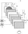
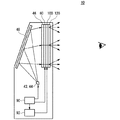
図1は、立体画像表示装置10の構成を示す分解斜視図である。本実施形態の立体画像表示装置10は、クロストークが少なく鮮明な立体画像の表示と、高精細な2次元画像の表示を両立することを目的とする。
FIG. 1 is an exploded perspective view showing the configuration of the stereoscopic
立体画像表示装置10は、光源部40、透過位置切替部50、画像表示部80、出射側偏光板72、切替制御部90、及び画像出力部92を備える。
光源部40は、観察者の左目及び右目に向けて独立して無偏光を投影する。光源部40は、左目用の無偏光を発する左目用光源42と、右目用の無偏光を発する右目用光源44と、左目用光源42から出射された光を観察者の左目に投影し、右目用光源44から出射された光を観察者の右目に投影する投影レンズ46とを有する。左目用光源42は、投影レンズ46の光軸に対して観察者の左目の反対側、すなわち、観察者から向かって右側に配置される。一方、右目用光源44は、投影レンズ46の光軸に対して観察者の右目と反対側、すなわち、観察者から向かって左側に配置される。
The stereoscopic
The
投影レンズ46は、例えばサーキュラーフレネルレンズである。あるいは、投影レンズ46は、垂直方向の稜線を有するリニアフレネルレンズと、水平方向の稜線を有するリニアフレネルレンズとを光線の進行方向に重ねて有してもよい。
The
画像表示部80は、パターニングされた透明電極を内側に対向して有する2枚のガラス基板の間に、液晶材料を封入した液晶表示素子である。画像表示部80は、左目用の視差画像を表示する左目画像表示領域82と、右目用の視差画像を表示する右目画像表示領域84とを垂直又は水平方向に交互に繰り返し有する。以下、画像表示部80が、左目画像表示領域82と右目画像表示領域84を垂直方向に交互に繰り返し有しており、直交部66は、上側から数えて奇数番目の水平ラインに左目画像対応領域67を、偶数番目の水平ラインに右目画像対応領域68を有する場合について説明する。
The
透過位置切替部50は、直交偏光切替部60及び入射側偏光板70を有する。直交偏光切替部60は、光源部40から左目画像表示領域82に向かう光と、光源部40から右目画像表示領域84に向かう光とを、互いに直交する直線偏光に変換すると共に、当該直線偏光の向きを切り替えて出射する。
The transmission
直交偏光切替部60は、偏光板62、偏光回転部64、及び直交部66を含む。偏光板62は、一様な方向に透過軸を有し、投影レンズ46から出射される無偏光を一様な向きの直線偏光にして出射する。偏光回転部64は、印加される電圧に応じて偏光板62から出射される直線偏光の偏光軸を90°回転させるか否かを切り替える。例えば、電圧が印加されていない場合、偏光回転部64は、偏光板62を透過した直線偏光を90°回転させて出射する。そして所定の電圧が切替制御部90から印加された場合に、偏光板62を透過した直線偏光の向きを変えることなく出射する。偏光回転部64は、例えば切り替え応答性に優れた液晶パネルであり、対向する一対の透明電極を内側に形成した一対のガラス基板の間に、液晶材料が封入されている。例えば、強誘電性液晶、及び反強誘電性液晶などである。
The orthogonal
直交部66は、左目画像対応領域67及び右目画像対応領域68を、画像表示部80における左目画像表示領域82及び右目画像表示領域84の配列と同一の方向に交互に繰り返し有している。左目画像対応領域67は、左目画像表示領域82に向けて投影される光を透過させる。右目画像対応領域68は、右目画像表示領域84に向けて投影される光を透過させる。左目画像対応領域67及び右目画像対応領域68の一方は、偏光回転部64から出射される直線偏光を90°回転して出射し、他方は、偏光回転部64から出射される直線偏光を同一の向きで出射するように設けられている。
The
入射側偏光板70は、画像表示部80の光源部40側に設けられ、直交偏光切替部60が出射する直線偏光と平行又は直交する透過軸を有する。したがって、入射側偏光板70は、直交部66から出射され互いに直交する直線偏光の一方を遮断し、他方を透過させる。そして、入射側偏光板70を透過した直線偏光のみを画像表示部80に入射させる。以下、本実施例の入射側偏光板70の透過軸は、偏光板62の透過軸と直交する場合について説明する。
The incident-side
画像表示部80は、電圧が印加されていない状態に於いて、入射する直線偏光を、所定の角度、例えばSTNの場合に90°回転させて出射する。そして、出射側偏光板72は、入射側偏光板70の透過軸と平行又は直交する透過軸を有して設けられ、画像表示部80から出射される直線偏光を遮断又は透過する。入射側偏光板70、画像表示部80、及び出射側偏光板72は、液晶ディスプレイ100を構成する。入射側偏光板70及び出射側偏光板72の透過軸がなす角度は、液晶ディスプレイ100がノーマリーホワイト及びノーマリーブラックのいずれかによって設定される。
In a state where no voltage is applied, the
直交部66は、例えば、パターニングされた位相差フィルタである。偏光回転部64から出射される直線偏光を90°回転させる領域は、1/2位相差板の光学主軸(進相軸または遅相軸)を、偏光回転部64から出射される直線偏光の偏向軸に対して約45°の角度で形成する。また、偏光回転部64から出射される直線偏光をそのままの向きで出射する領域は、1/2位相差板の光学主軸を、偏光回転部64から出射される直線偏光の偏向軸に対して平行または直行させて形成する。このようなパターニングは、形成すべきパターンに応じた異方性を、たとえば光配向法またはラビング法で直交部66に付与することによって行う。以下の実施例において、左目画像対応領域67は、偏光回転部64から出射される直線偏光を同一の向きで出射し、右目画像対応領域68は、偏光回転部64から出射される直線偏光を90°回転させて出射する場合について説明する。
The
直交偏光切替部60は、光源部40から出射される段階で既に左目又は右目の方向に指向している無偏光を偏光板62において一様な直線偏光に変換し、当該一様な直線偏光を直交部66において互いに直交する直線偏光に変換する。この間、直線偏光を屈折又は反射させる過程がないので、直交偏光切替部60は、精度の高い直線偏光を出射する。したがって入射側偏光板70は、互いに直交する高精度な直線偏光の一方を確実に遮断し、他方を効率よく透過させることができる。すなわち、透過位置切替部50は、光源部40の出射光を左目画像表示領域82及び右目画像表示領域84のいずれに入射させるかを精度良く切り替えることができる。
The orthogonal
偏光回転部64が出射する直線偏光の向きを90°切り替えると、左目画像対応領域67及び右目画像対応領域68から出射される直線偏光の向きがそれぞれ90°回転する。これにより、左目画像対応領域67及び右目画像対応領域68から出射される互いに直交する直線偏光のうち、入射側偏光板70を透過する直線偏光が切り替わる。つまり、偏光回転部64の切り替え前に入射側偏光板70を透過していた直線偏光は遮断され、偏光回転部64の切り替え前に入射側偏光板70で遮断されていた直線偏光は透過される。ここで、偏光回転部64は、直交部66に入射する直線偏光の向きを遅延無く切り替えることができる。したがって、透過位置切替部50は、光源部40の切り替えと同時に、光源部40の出射光を左目画像表示領域82及び右目画像表示領域84のいずれに入射させるかを遅延なく切り替えることができる。これにより、左目用の画像または右目用の画像が逆の目に投影されることがないので、立体画像のクロストークが低減される。
When the direction of the linearly polarized light emitted from the
以下、図2から図5を参照して、図1に示した立体画像表示装置10の動作を説明する。
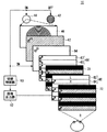
図2及び図3は、立体画像表示装置10が立体画像を表示する場合(以下、3Dモードという)の動作を示す。なお、図中各素子の前面に示す矢印は、出射する直線偏光の向きを示す。3Dモードにおいて、切替制御部90は、画像出力部92に視差画像を出力するように指示する。これを受けて画像出力部92は、左目画像表示領域82に左目用の視差画像を出力し、右目画像表示領域84に右目用の視差画像を出力する。
Hereinafter, the operation of the stereoscopic
2 and 3 show operations when the stereoscopic
図2の状態において、切替制御部90は、左目用光源42を点灯、右目用光源44を消灯させると同時に、偏光回転部64に電圧を印加しない。これにより、偏光板62から出射された直線偏光は、偏光回転部64で90°回転して出射される。そして左目画像対応領域67に入射した直線偏光は、入射時と同じ向きで左目画像対応領域67から出射され、入射側偏光板70を透過して左目画像表示領域82に入射する。そして、左目画像表示領域82に表示されている左目用視差画像を投影して出射側偏光板72から出射され、観察者の左目に到達する。
In the state of FIG. 2, the switching
一方、偏光回転部64から出射され右目画像対応領域68に入射する直線偏光は、右目画像対応領域68で90°回転されて出射され、入射側偏光板70で遮断される。これにより、左目用光源42から出射された光は右目画像表示領域84に到達しない。したがって、右目画像表示領域84に表示されている右目用視差画像は観察者の左目に投影されることがない。
On the other hand, the linearly polarized light emitted from the
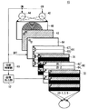
次に、切替制御部90は、図3に示すように、左目用光源42を消灯、右目用光源44を点灯させると同時に、偏光回転部64に所定の電圧を印加する。これにより、偏光板62から出射された直線偏光は、偏光回転部64で回転されることなく同一の向きで出射される。そして右目画像対応領域68に入射した直線偏光は、右目画像対応領域68で90°回転して出射され、入射側偏光板70を透過して右目画像表示領域84に入射する。そして、右目画像表示領域84に表示されている右目用視差画像を投影して出射側偏光板72から出射され、観察者の右目に到達する。
Next, as shown in FIG. 3, the switching
一方、偏光回転部64から出射され左目画像対応領域67に入射する直線偏光は、入射時と同じ向きで左目画像対応領域67から出射され、入射側偏光板70で遮断される。これにより、右目用光源44から出射された光は左目画像表示領域82に到達しない。したがって、左目画像表示領域82に表示されている左目用視差画像は観察者の左目に投影されることがない。
On the other hand, the linearly polarized light emitted from the
なお、切替制御部90は、画像表示部80が動画のフレームを更新するたびに、光源部40から出射する光を、左目画像表示領域82に入射させて観察者の左目に投影するか、右目画像表示領域84に入射させて観察者の右目に投影するかを少なくとも1回切り替えるべく、光源部40及び透過位置切替部50を制御する。したがって、動画を構成する各画像をもれなく観察者の両目に提供できる。
Note that the switching
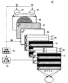
図4及び図5は、立体画像表示装置10が2次元画像を表示する場合(以下、2Dモードという)の動作を示す。切替制御部90は、画像表示部80が2次元画像を表示する場合には、光源部40に、観察者の両目に向けて同時に無偏光を投影させる。つまり、切替制御部90は、2Dモードにおいて、左目用光源42及び右目用光源44をいずれも点灯させる。そして、偏光回転部64に電圧を印加するか否かを一定の周期で切り替える。例えば、図4に示す状態において、切替制御部90は、偏光回転部64に電圧を印加しない。この状態において、左目用光源42及び右目用光源44から出射された光は画像表示部80の水平ラインの奇数列、すなわち左目画像表示領域82に入射して観察者の両目に到達する。この場合、画像表示部80の偶数列に光は入射しない。
4 and 5 show operations when the stereoscopic
一方、図5に示す状態において、切替制御部90は偏光回転部64に電圧を印加する。これにより、左目用光源42及び右目用光源44から出射された光は画像表示部80の水平ラインの偶数列、すなわち右目画像表示領域84に入射して観察者の両目に到達する。この場合、画像表示部80の奇数列、すなわち左目画像表示領域82に光は入射しない。したがって、2Dモードにおいて、左目画像表示領域82に表示される奇数ラインの2次元画像及び右目画像表示領域84に表示される偶数ラインの2次元画像が観察者の左目および右目のそれぞれに交互に投影される。
On the other hand, in the state shown in FIG. 5, the switching
ここで、人間の目は、50〜60Hz未満の周波数の光をフリッカーとして認識する。したがって、画像表示部80のリフレッシュレートは、例えばフリッカーを認識しない60Hzである。これに対して、切替制御部90は、光源部40から出射する光を左目画像表示領域82に入射させて観察者の左目に投影するか、右目画像表示領域84に入射させて観察者の右目に投影するかを、画像表示部80のリフレッシュレートの少なくとも倍、すなわち120Hzの周波数で切り替える。したがって、左目及び右目のそれぞれに投影される光の周波数が、画像表示部80のリフレッシュレートと同等以上になり、フリッカーが発生しない。以上の動作により、立体画像表示装置10は、2次元画像を表示する場合に、画像表示部80の最大の解像度で高精細な画像を表示できる。
Here, the human eye recognizes light having a frequency of 50 to less than 60 Hz as flicker. Therefore, the refresh rate of the
図6は、立体画像表示装置10が反射鏡48を含む場合の構成の一例を示す。本実施例の立体画像表示装置10において、光源部40は、図1に示した構成に加えて、反射鏡48を備える。反射鏡48は、左目用光源42及び右目用光源44から出射された無偏光を反射する。投影レンズ46は、反射鏡48で反射された左目用光源42の出射光を観察者の左目に投影し、反射鏡48で反射された右目用光源44の出射光を観察者の右目に投影する。このような構成によれば、左目用光源42及び右目用光源44から投影レンズ46に至る光路を反射鏡48が反射するので、立体画像表示装置10が小型化される。そして、観察者に向けて投影される光は、反射鏡48及び投影レンズ46よりも観察者側で直線偏光になり、その後、画像表示部80から出射するまで反射または屈折されることがない。したがって、透過位置切替部50は、光源部40の出射光を左目画像表示領域82に入射させるか右目画像表示領域84に入射させるかを、精度の高い直線偏光で確実に切り替えることができる。
FIG. 6 shows an example of a configuration when the stereoscopic
本実施例の立体画像表示装置10は、さらに液晶ディスプレイ100の前面に拡散板120を備える。拡散板120は、液晶ディスプレイ100から出射する画像光を垂直方向に拡散する。拡散板120は、液晶ディスプレイ100から出射する画像光を水平方向には拡散しない。これにより、3Dモードにおけるクロストークを増大させることなく、立体画像表示装置10の視野角を垂直方向に広げることができる。
The stereoscopic
以上の説明から明らかなように本実施形態の立体画像表示装置10によれば、クロストークが少なく鮮明な立体画像の表示と、高精細な2次元画像の表示を両立することができる。
As is clear from the above description, according to the stereoscopic
なお、上述の実施例は、左目画像対応領域67が、偏光回転部64から出射される直線偏光を同一の向きで出射し、右目画像対応領域68が、偏光回転部64から出射される直線偏光を90°回転させて出射する場合の立体画像表示装置10の動作について説明した。しかしながら、立体画像表示装置10の構成及び動作はこれに限られない。たとえば、左目画像対応領域67が、偏光回転部64から出射される直線偏光を90°回転させて出射し、右目画像対応領域68が、偏光回転部64から出射される直線偏光を同一の向きで出射してもよい。この場合、切替制御部90は、3D表示モードにおいて、左目用光源42を点灯させるときに偏光回転部64に電圧を印加して、偏光板62から出射される直線偏向をそのままの向きで透過させる。そして、右目用光源44を点灯させるときに偏光回転部64に電圧を印加せず、偏光板62から出射される直線偏光を約90°回転して出射する。これにより、図2から図6で説明した実施例と同様の効果を奏する。
In the above-described embodiment, the left-eye
また、さらに他の実施例として、入射側偏光板70の透過軸は、偏光板62の透過軸と平行に設けられていてもよい。そして、左目画像対応領域67が、偏光回転部64から出射される直線偏光を同一の向きで出射し、右目画像対応領域68が、偏光回転部64から出射される直線偏光を90°回転させて出射する場合には、切替制御部90は、3D表示モードにおいて、左目用光源42を点灯させるときに偏光回転部64に電圧を印加して、偏光板62から出射される直線偏向をそのままの向きで透過させる。そして、右目用光源44を点灯させるときに偏光回転部64に電圧を印加せず、偏光板62から出射される直線偏光を約90°回転して出射する。これにより、図2から図6で説明した実施例と同様の効果を奏する。
As still another example, the transmission axis of the incident
また、偏光板62と入射側偏光板70の透過軸が平行であって、左目画像対応領域67が、偏光回転部64から出射される直線偏光を90°回転させて出射し、右目画像対応領域68が、偏光回転部64から出射される直線偏光を同一の向きで出射してもよい。この場合、切替制御部90は、3D表示モードにおいて、左目用光源42を点灯させるときに偏光回転部64に電圧を印加せず、偏光板62から出射される直線偏向を約90°回転して出射する。そして、右目用光源44を点灯させるときに偏光回転部64に電圧を印加し、偏光板62から出射される直線偏光をそのままの向きで透過させる。これにより、図2から図6で説明した実施例と同様の効果を奏する。
Further, the transmission axes of the
以上、本発明を実施の形態を用いて説明したが、本発明の技術的範囲は上記実施の形態に記載の範囲には限定されない。上記実施形態に、多様な変更又は改良を加えることができることが当業者に明らかである。その様な変更又は改良を加えた形態も本発明の技術的範囲に含まれることが、特許請求の範囲の記載から明らかである。 As mentioned above, although this invention was demonstrated using embodiment, the technical scope of this invention is not limited to the range as described in the said embodiment. It will be apparent to those skilled in the art that various modifications or improvements can be added to the above-described embodiment. It is apparent from the scope of the claims that the embodiments added with such changes or improvements are also included in the technical scope of the present invention.
10・・・立体画像表示装置、40・・・光源部、42・・・左目用光源、44・・・右目用光源、46・・・投影レンズ、48・・・反射鏡、50・・・透過位置切替部、60・・・直交偏光切替部、62・・・偏光板、64・・・偏光回転部、66・・・直交部、67・・・左目画像対応領域、68・・・右目画像対応領域、70・・・入射側偏光板、72・・・出射側偏光板、80・・・画像表示部、82・・・左目画像表示領域、84・・・右目画像表示領域、90・・・切替制御部、92・・・画像出力部、100・・・液晶ディスプレイ、120・・・拡散板
DESCRIPTION OF
Claims (7)
観察者の左目及び右目に向けて独立して交互に無偏光を投影する光源部と、
左目用の視差画像を表示する左目画像表示領域と右目用の視差画像を表示する右目画像表示領域とを垂直又は水平方向に交互に繰り返し有する画像表示部と、
前記光源部の出射光を前記左目画像表示領域に入射させるか前記右目画像表示領域に入射させるかを切り替える透過位置切替部と、
前記光源部が観察者の左目に向けて光を投影するときには当該光源部の出射光を前記左目画像表示領域に入射させ、前記光源部が観察者の右目に向けて光を投影するときには当該光源部の出射光を前記右目画像表示領域に入射させるべく、前記光源部及び前記透過位置切替部を一定の周期で切り替える切替制御部と
を備える立体画像表示装置。 A stereoscopic image display device that displays a stereoscopic image by projecting parallax images to the left and right eyes of an observer,
A light source unit that alternately and independently projects non-polarized light toward the left and right eyes of the observer;
An image display unit that alternately repeats a left-eye image display region for displaying a left-eye parallax image and a right-eye image display region for displaying a right-eye parallax image in the vertical or horizontal direction;
A transmission position switching unit that switches whether the light emitted from the light source unit is incident on the left-eye image display region or the right-eye image display region;
When the light source unit projects light toward the left eye of the observer, the light emitted from the light source unit enters the left eye image display area, and when the light source unit projects light toward the right eye of the viewer, the light source A stereoscopic image display device comprising: a switching control unit that switches the light source unit and the transmission position switching unit at a constant cycle so that the emitted light of the unit enters the right-eye image display region.
前記光源部から前記左目画像表示領域に向かう光と、前記光源部から前記右目画像表示領域に向かう光とを、互いに直交する直線偏光に変換すると共に、当該直線偏光の向きを前記一定の周期で交互に切り替えて出射する直交偏光切替部と、
前記画像表示部の前記光源部側に設けられ、前記直交偏光切替部が出射する直線偏光と平行又は直交する透過軸を有する入射側偏光板と
を有する請求項1に記載の立体画像表示装置。 The transmission position switching unit is
The light traveling from the light source unit toward the left eye image display region and the light traveling from the light source unit toward the right eye image display region are converted into linearly polarized light orthogonal to each other, and the direction of the linearly polarized light is changed at the predetermined period. An orthogonal polarization switching unit that alternately switches and emits light; and
The stereoscopic image display device according to claim 1, further comprising: an incident-side polarizing plate that is provided on the light source side of the image display unit and has a transmission axis that is parallel or orthogonal to the linearly polarized light emitted from the orthogonal polarization switching unit.
偏光板と、
前記偏光板を透過した直線偏光を90°回転させて出射するか、同一の向きで出射するかを切り替える偏光回転部と、
前記左目画像表示領域に投影される光を透過させる左目画像対応領域と、前記右目画像表示領域に投影される光を透過させる右目画像対応領域とを、前記画像表示部における前記左目画像表示領域及び前記右目画像表示領域の配列と同一の方向に交互に繰り返し有し、前記左目画像対応領域及び前記右目画像対応領域の一方は、前記偏光回転部から出射される直線偏光を90°回転して出射し、他方は、前記偏光回転部から出射される直線偏光を同一の向きで出射するように設けられている直交部と
を含む、請求項2に記載の立体画像表示装置。 The orthogonal polarization switching unit is
A polarizing plate;
A polarization rotator that switches whether the linearly polarized light that has passed through the polarizing plate is rotated by 90 ° or is emitted in the same direction;
A left-eye image corresponding region that transmits light projected on the left-eye image display region, and a right-eye image corresponding region that transmits light projected on the right-eye image display region, the left-eye image display region in the image display unit, and The left-eye image corresponding region and the right-eye image corresponding region are alternately repeated in the same direction as the arrangement of the right-eye image display region, and one of the left-eye image corresponding region and the right-eye image corresponding region is emitted by rotating the linearly polarized light emitted from the polarization rotation unit by 90 °. The other of the three-dimensional image display devices according to claim 2, further comprising: an orthogonal part provided so as to emit linearly polarized light emitted from the polarization rotating part in the same direction.
左目用の無偏光を発する左目用光源と、
右目用の無偏光を発する右目用光源と、
前記左目用光源及び前記右目用光源から出射された無偏光を反射する反射鏡と、
前記反射鏡で反射された前記左目用光源の出射光を観察者の左目に投影し、前記反射鏡で反射された前記右目用光源の出射光を観察者の右目に投影する投影レンズと、
を有する、請求項1に記載の立体画像表示装置。 The light source unit is
A light source for the left eye that emits unpolarized light for the left eye;
A light source for the right eye that emits unpolarized light for the right eye;
A reflecting mirror that reflects non-polarized light emitted from the left-eye light source and the right-eye light source;
A projection lens that projects the emitted light of the left-eye light source reflected by the reflecting mirror to the left eye of the observer, and projects the emitted light of the right-eye light source reflected by the reflecting mirror and the right eye of the observer;
The stereoscopic image display device according to claim 1, comprising:
Priority Applications (1)
| Application Number | Priority Date | Filing Date | Title |
|---|---|---|---|
| JP2004111232A JP4349963B2 (en) | 2004-04-05 | 2004-04-05 | Stereoscopic image display device |
Applications Claiming Priority (1)
| Application Number | Priority Date | Filing Date | Title |
|---|---|---|---|
| JP2004111232A JP4349963B2 (en) | 2004-04-05 | 2004-04-05 | Stereoscopic image display device |
Publications (2)
| Publication Number | Publication Date |
|---|---|
| JP2005292722A true JP2005292722A (en) | 2005-10-20 |
| JP4349963B2 JP4349963B2 (en) | 2009-10-21 |
Family
ID=35325671
Family Applications (1)
| Application Number | Title | Priority Date | Filing Date |
|---|---|---|---|
| JP2004111232A Expired - Lifetime JP4349963B2 (en) | 2004-04-05 | 2004-04-05 | Stereoscopic image display device |
Country Status (1)
| Country | Link |
|---|---|
| JP (1) | JP4349963B2 (en) |
Cited By (12)
| Publication number | Priority date | Publication date | Assignee | Title |
|---|---|---|---|---|
| WO2008124709A1 (en) * | 2007-04-09 | 2008-10-16 | 3M Innovative Properties Company | Autostereoscopic liquid crystal display apparatus |
| JP2010507332A (en) * | 2006-10-18 | 2010-03-04 | リアル・ディ | Dual ZScreen (R) projection |
| JP2010096900A (en) * | 2008-10-15 | 2010-04-30 | Sony Corp | Retardation element and display device |
| US7750982B2 (en) | 2008-03-19 | 2010-07-06 | 3M Innovative Properties Company | Autostereoscopic display with fresnel lens element and double sided prism film adjacent a backlight having a light transmission surface with left and right eye light sources at opposing ends modulated at a rate of at least 90 hz |
| JP2010224550A (en) * | 2010-04-28 | 2010-10-07 | Sony Corp | Phase difference element and display device |
| JP2010224129A (en) * | 2009-03-23 | 2010-10-07 | Sharp Corp | Stereoscopic image display device |
| JP2011133652A (en) * | 2009-12-24 | 2011-07-07 | Sony Corp | Display panel module, semiconductor integrated circuit, driving method of pixel array unit, and electronic apparatus |
| CN102331636A (en) * | 2011-09-27 | 2012-01-25 | 昆山龙腾光电有限公司 | Liquid crystal display panel and three-dimensional display device |
| WO2012066778A1 (en) * | 2010-11-17 | 2012-05-24 | パナソニック株式会社 | Illuminating device, and liquid crystal display device and image display device using same |
| JP2012133345A (en) * | 2010-11-30 | 2012-07-12 | Semiconductor Energy Lab Co Ltd | Liquid crystal display device and driving method for liquid crystal display device |
| JP2012203111A (en) * | 2011-03-24 | 2012-10-22 | Arisawa Mfg Co Ltd | Stereoscopic image display device |
| JP2012252302A (en) * | 2011-06-07 | 2012-12-20 | Arisawa Mfg Co Ltd | Stereoscopic image display device |
Families Citing this family (1)
| Publication number | Priority date | Publication date | Assignee | Title |
|---|---|---|---|---|
| KR20150092424A (en) | 2014-02-04 | 2015-08-13 | 삼성디스플레이 주식회사 | Display device |
-
2004
- 2004-04-05 JP JP2004111232A patent/JP4349963B2/en not_active Expired - Lifetime
Cited By (19)
| Publication number | Priority date | Publication date | Assignee | Title |
|---|---|---|---|---|
| JP2010507332A (en) * | 2006-10-18 | 2010-03-04 | リアル・ディ | Dual ZScreen (R) projection |
| US8339444B2 (en) | 2007-04-09 | 2012-12-25 | 3M Innovative Properties Company | Autostereoscopic liquid crystal display apparatus |
| WO2008124709A1 (en) * | 2007-04-09 | 2008-10-16 | 3M Innovative Properties Company | Autostereoscopic liquid crystal display apparatus |
| US7847869B2 (en) | 2008-03-19 | 2010-12-07 | 3M Innovative Properties Company | Autostereoscopic display with fresnel lens element and double sided prism adjacent a backlight having a transmission surface with opposed first and second light sources alternately modulated at 90 Hz |
| US7750982B2 (en) | 2008-03-19 | 2010-07-06 | 3M Innovative Properties Company | Autostereoscopic display with fresnel lens element and double sided prism film adjacent a backlight having a light transmission surface with left and right eye light sources at opposing ends modulated at a rate of at least 90 hz |
| US8223280B2 (en) | 2008-10-15 | 2012-07-17 | Sony Corporation | Phase difference element and display device |
| US8089569B2 (en) | 2008-10-15 | 2012-01-03 | Sony Corporation | Phase difference element and display device |
| JP2010096900A (en) * | 2008-10-15 | 2010-04-30 | Sony Corp | Retardation element and display device |
| JP2010224129A (en) * | 2009-03-23 | 2010-10-07 | Sharp Corp | Stereoscopic image display device |
| JP2011133652A (en) * | 2009-12-24 | 2011-07-07 | Sony Corp | Display panel module, semiconductor integrated circuit, driving method of pixel array unit, and electronic apparatus |
| JP2010224550A (en) * | 2010-04-28 | 2010-10-07 | Sony Corp | Phase difference element and display device |
| WO2012066778A1 (en) * | 2010-11-17 | 2012-05-24 | パナソニック株式会社 | Illuminating device, and liquid crystal display device and image display device using same |
| US9201187B2 (en) | 2010-11-17 | 2015-12-01 | Panasonic Intellectual Property Management Co., Ltd. | Light-emitting device, and liquid crystal display device and image display device that use the same |
| JP5899520B2 (en) * | 2010-11-17 | 2016-04-06 | パナソニックIpマネジメント株式会社 | Light irradiation device and liquid crystal display device using the same |
| JP2012133345A (en) * | 2010-11-30 | 2012-07-12 | Semiconductor Energy Lab Co Ltd | Liquid crystal display device and driving method for liquid crystal display device |
| US9224350B2 (en) | 2010-11-30 | 2015-12-29 | Semiconductor Energy Laboratory Co., Ltd. | Liquid crystal display device and driving method of liquid crystal display device |
| JP2012203111A (en) * | 2011-03-24 | 2012-10-22 | Arisawa Mfg Co Ltd | Stereoscopic image display device |
| JP2012252302A (en) * | 2011-06-07 | 2012-12-20 | Arisawa Mfg Co Ltd | Stereoscopic image display device |
| CN102331636A (en) * | 2011-09-27 | 2012-01-25 | 昆山龙腾光电有限公司 | Liquid crystal display panel and three-dimensional display device |
Also Published As
| Publication number | Publication date |
|---|---|
| JP4349963B2 (en) | 2009-10-21 |
Similar Documents
| Publication | Publication Date | Title |
|---|---|---|
| JP4644594B2 (en) | 3D image display device | |
| JP4794827B2 (en) | Display device and driving method thereof | |
| EP1706778B1 (en) | Three-dimensional display device with optical path length adjuster | |
| KR100608023B1 (en) | Projection type 3D image display device using one projector | |
| JP4349963B2 (en) | Stereoscopic image display device | |
| US10701348B2 (en) | High brightness stereoscopic image screening device using modulator asymmetry drive, and method for operating same | |
| CN100480839C (en) | Projection-type 3-D image display using single projector | |
| CN103389612B (en) | Projection device for providing multi-view image | |
| JP2999952B2 (en) | Polarized glasses type stereoscopic image display | |
| JP2005065055A (en) | Projection type display device and projection type display method | |
| JP2002296540A (en) | Stereoscopic image display device without spectacles | |
| JP2953433B2 (en) | 3D display device | |
| JP2966782B2 (en) | 3D image display device | |
| JP4609001B2 (en) | Pointer device | |
| KR100909274B1 (en) | Stereoscopic projection system and device for stereoscopic projection | |
| US9442301B2 (en) | Autostereoscopic display device and autostereoscopic display method using the same | |
| KR100909275B1 (en) | Stereoscopic projection system and device for stereoscopic projection | |
| JP2966783B2 (en) | 3D image display device | |
| JP2999953B2 (en) | Stereoscopic image display using polarized glasses | |
| KR20000039515A (en) | Display device for three dimensional image | |
| JPS59176720A (en) | stereoscopic projection device | |
| JP2013190726A (en) | Polarization switching device and image display device | |
| JP2006163191A (en) | 3D projector | |
| KR20060089407A (en) | Stereoscopic Display | |
| KR20060091543A (en) | Lossless Polarized Stereoscopic Display Device |
Legal Events
| Date | Code | Title | Description |
|---|---|---|---|
| A621 | Written request for application examination |
Free format text: JAPANESE INTERMEDIATE CODE: A621 Effective date: 20060519 |
|
| A977 | Report on retrieval |
Free format text: JAPANESE INTERMEDIATE CODE: A971007 Effective date: 20090413 |
|
| A131 | Notification of reasons for refusal |
Free format text: JAPANESE INTERMEDIATE CODE: A131 Effective date: 20090421 |
|
| A521 | Request for written amendment filed |
Free format text: JAPANESE INTERMEDIATE CODE: A523 Effective date: 20090605 |
|
| TRDD | Decision of grant or rejection written | ||
| A01 | Written decision to grant a patent or to grant a registration (utility model) |
Free format text: JAPANESE INTERMEDIATE CODE: A01 Effective date: 20090630 |
|
| A01 | Written decision to grant a patent or to grant a registration (utility model) |
Free format text: JAPANESE INTERMEDIATE CODE: A01 |
|
| A61 | First payment of annual fees (during grant procedure) |
Free format text: JAPANESE INTERMEDIATE CODE: A61 Effective date: 20090721 |
|
| FPAY | Renewal fee payment (event date is renewal date of database) |
Free format text: PAYMENT UNTIL: 20120731 Year of fee payment: 3 |
|
| R150 | Certificate of patent or registration of utility model |
Ref document number: 4349963 Country of ref document: JP Free format text: JAPANESE INTERMEDIATE CODE: R150 Free format text: JAPANESE INTERMEDIATE CODE: R150 |
|
| FPAY | Renewal fee payment (event date is renewal date of database) |
Free format text: PAYMENT UNTIL: 20120731 Year of fee payment: 3 |
|
| FPAY | Renewal fee payment (event date is renewal date of database) |
Free format text: PAYMENT UNTIL: 20130731 Year of fee payment: 4 |
|
| R250 | Receipt of annual fees |
Free format text: JAPANESE INTERMEDIATE CODE: R250 |
|
| R250 | Receipt of annual fees |
Free format text: JAPANESE INTERMEDIATE CODE: R250 |
|
| R250 | Receipt of annual fees |
Free format text: JAPANESE INTERMEDIATE CODE: R250 |
|
| R250 | Receipt of annual fees |
Free format text: JAPANESE INTERMEDIATE CODE: R250 |
|
| R250 | Receipt of annual fees |
Free format text: JAPANESE INTERMEDIATE CODE: R250 |
|
| R250 | Receipt of annual fees |
Free format text: JAPANESE INTERMEDIATE CODE: R250 |
|
| R250 | Receipt of annual fees |
Free format text: JAPANESE INTERMEDIATE CODE: R250 |
|
| R250 | Receipt of annual fees |
Free format text: JAPANESE INTERMEDIATE CODE: R250 |
|
| R250 | Receipt of annual fees |
Free format text: JAPANESE INTERMEDIATE CODE: R250 |
|
| R250 | Receipt of annual fees |
Free format text: JAPANESE INTERMEDIATE CODE: R250 |
|
| R250 | Receipt of annual fees |
Free format text: JAPANESE INTERMEDIATE CODE: R250 |
|
| R250 | Receipt of annual fees |
Free format text: JAPANESE INTERMEDIATE CODE: R250 |
|
| EXPY | Cancellation because of completion of term |