JP2005292689A - Fixing device - Google Patents
Fixing device Download PDFInfo
- Publication number
- JP2005292689A JP2005292689A JP2004110885A JP2004110885A JP2005292689A JP 2005292689 A JP2005292689 A JP 2005292689A JP 2004110885 A JP2004110885 A JP 2004110885A JP 2004110885 A JP2004110885 A JP 2004110885A JP 2005292689 A JP2005292689 A JP 2005292689A
- Authority
- JP
- Japan
- Prior art keywords
- pressure roller
- fixing
- roller
- bias
- voltage
- Prior art date
- Legal status (The legal status is an assumption and is not a legal conclusion. Google has not performed a legal analysis and makes no representation as to the accuracy of the status listed.)
- Withdrawn
Links
Images

Landscapes
- Fixing For Electrophotography (AREA)
- Control Or Security For Electrophotography (AREA)
Abstract
【課題】 耐久使用で発生する定着尾引きを防止することを目的とする。
【解決手段】 加圧ローラ表面給電の定着器で、加圧ローラとバイアス電源の間に電流検出手段を設けておき、定着ニップに紙が突入した際に流れる電流が一定になるように加圧ローラに印加する電圧を制御する。
【選択図】 図1PROBLEM TO BE SOLVED: To prevent fixing tailing generated by durable use.
A pressure roller surface-fed fixing device is provided with a current detection means between a pressure roller and a bias power source so that the current flowing when paper enters the fixing nip is constant. Controls the voltage applied to the roller.
[Selection] Figure 1
Description
本発明は、画像形成装置の定着装置に関するものである。 The present invention relates to a fixing device of an image forming apparatus.
従来の定着装置の構成を図10に示す。 A configuration of a conventional fixing device is shown in FIG.
図10に示すところの21は従来の定着装置で、1は定着ローラ、2は定着ローラ芯金、3は弾性層、4は定着ローラ表層のPFA、5は加圧ローラ、6は加圧ローラ芯金、7はシリコーンゴム、8はPFA、9はヒータ、10は温度検出手段であるところとのサーミスタ、11は分離爪、12は分離爪を加圧するバネ、Nは定着ニップ、13は紙を定着ニップNに案内する入り口ガイド、14は排紙ガイド、15は給電ブラシ、16は絶縁板、17は給電コード、18はバイアス電源、19は定着外装カバー、20は定着フレームである。 10, 21 is a conventional fixing device, 1 is a fixing roller, 2 is a fixing roller core, 3 is an elastic layer, 4 is a PFA on the surface of the fixing roller, 5 is a pressure roller, and 6 is a pressure roller. Metal core, 7 is silicone rubber, 8 is PFA, 9 is a heater, 10 is a thermistor that is temperature detecting means, 11 is a separation claw, 12 is a spring that presses the separation claw, N is a fixing nip, and 13 is paper. , A discharge guide, 15 a power supply brush, 16 an insulating plate, 17 a power supply cord, 18 a bias power supply, 19 a fixing exterior cover, and 20 a fixing frame.
定着ローラ1は、アルミ製のパイプ形状の芯金2上にシリコーンゴム製の弾性層3を設け、表面を絶縁性のPFA樹脂4で被覆したものである。
The
定着ローラ1は、定着ローラ内に設けたヒータ9により加熱され温調制御される。
The
定着ローラ1の温度は、サーミスタ10で検出し、ヒータの駆動にフィードバックする。
The temperature of the
加圧ローラ5は、鉄製の芯金6上にシリコーンゴム弾性層を設け表層にカーボンを分散した導電性のPFA樹脂の表層離型層8を設けている。
The
加圧ローラ4の表面硬度は、アスカーC硬度計を押し圧9.8Nで当接させた場合に55〜65°程度である。 The surface hardness of the pressure roller 4 is about 55 to 65 ° when the Asker C hardness meter is brought into contact with a pressing pressure of 9.8 N.
加圧ローラ4は、定着ローラ1に加圧圧接される。当接圧は、98Nから980N程度である。
The pressure roller 4 is in pressure contact with the
定着ローラの芯金2は、電気的に接地されている。
The
加圧ローラの表面には、給電ブラシ16が当接している。
The
給電ブラシは、直径が10ミクロンのステンレス繊維を20本束ねて、その束を5個程度をアルミニウム板金ではさんだものである。 The power supply brush is a bundle of 20 stainless fibers having a diameter of 10 microns, and about 5 bundles are sandwiched between aluminum sheets.
給電ブラシ15は、絶縁部材16により定着フレーム20電気的に絶縁している。
The
給電ブラシ15には、電源コード17が接続しており電源18から電圧供給を行う。
A
このバイアス構成により定着ローラ1と加圧ローラ4には、電位差を形成する。
With this bias configuration, a potential difference is formed between the
この電位差により、紙上のトナーが定着ニップNの前で定着ローラに転移することで発生するオフセットや、定着ローラや、加圧ローラの微少な帯電により紙上のトナーが乱される飛び散りといた画像不良を防止する。 Due to this potential difference, the image defect that the toner on the paper is scattered by the offset generated by the transfer of the toner on the paper to the fixing roller before the fixing nip N, or the toner on the paper is disturbed by the slight charge of the fixing roller or the pressure roller. To prevent.
定着器21での紙搬送は、定着入り口ガイド13に沿って未定着画像を載せた紙を定着ローラ1と加圧ローラ5で形成する定着ニップNに導く。
In the conveyance of the paper in the
紙上のトナー像は、加熱加圧されて紙に定着する。 The toner image on the paper is heated and pressed and fixed on the paper.
紙は、その後分離爪11より分離されて、排紙ガイド14に支持されながら、定着器後方へと搬送されトナー画像の定着を終する。
定着ローラと加圧ローラとの間に定着バイアスを印加する従来技術として特許文献1がある。
As a conventional technique for applying a fixing bias between a fixing roller and a pressure roller, there is
しかしながら、上記従来例では、耐久使用により定着ローラ表面に紙紛やトナーの成分が付着して帯電しやすくなる。 However, in the above-mentioned conventional example, paper dust and toner components adhere to the surface of the fixing roller due to durable use, and are easily charged.
定着ローラが帯電すると、定着ローラ、加圧ローラ間の電位コントラストが小さくなり、画像不良が発生するようになるといった問題があった。 When the fixing roller is charged, there is a problem that the potential contrast between the fixing roller and the pressure roller is reduced, and an image defect occurs.
このことを防止する手段として、最初から加圧バイアスを大きくすることが考えられるが、上下の電位コントラストを大きくすると、紙が定着ローラに静電吸着し、分離爪で分離することができずに、紙詰まりを発生してしまうという問題があった。 As a means to prevent this, it is conceivable to increase the pressure bias from the beginning. However, if the upper and lower potential contrasts are increased, the paper is electrostatically attracted to the fixing roller and cannot be separated by the separation claw. There was a problem that paper jam occurred.
本発明は、以上の点に着目して成されたもので、耐久使用で発生する定着尾引きを防止する定着装置を提供することを目的とする。 The present invention has been made paying attention to the above points, and an object of the present invention is to provide a fixing device that prevents fixing tailing that occurs during durable use.
1.上記目的を達成するために本出願にかかる第一の発明は、
導電離型層を有する加圧ローラにバイアス手段により給電を行う画像形成装置の定着装置において
加圧ローラに流れる電流を検出する手段を設けており、定着ローラと加圧ローラで形成する定着ニップに紙が入ったときに加圧ローラに流れる電流を検出し、その電流値が所定の値になるようにバイアス電源の電圧を制御することを特徴とする。
1. In order to achieve the above object, the first invention according to the present application is:
In a fixing device of an image forming apparatus that supplies power to a pressure roller having a conductive release layer by bias means, a means for detecting a current flowing through the pressure roller is provided, and a fixing nip formed by the fixing roller and the pressure roller is provided. It is characterized in that the current flowing through the pressure roller when paper enters is detected, and the voltage of the bias power supply is controlled so that the current value becomes a predetermined value.
上記構成において定着ニップに紙が入ったときの電流が一定になるように加圧ローラの電圧を制御することは、定着ローラと加圧ローラの表面電位が定着ローラの帯電によらず一定になるように作用する。 In the above configuration, controlling the voltage of the pressure roller so that the current when the paper enters the fixing nip is constant is that the surface potential of the fixing roller and the pressure roller is constant regardless of the charging of the fixing roller. Acts as follows.
2.上記目的を達成するために本出願にかかる第二の発明は、
加圧ローラ表面の導電離型層を設けており、定着ローラ芯金にバイアスを印加する画像形成装置の定着装置において
加圧ローラは電気的に接地されており、かつ、加圧ローラに流れる電流を検出する電流検出手段を備えていて、定着ローラに電圧を印加するバイアス手段は、電圧の変更が可能な構成であって、定着ローラと加圧ローラで形成する定着ニップに紙が入ったときに加圧ローラに流れる電流を検出し、その電流値が所定の値になるように定着ローラのバイアス電源の電圧を制御することを特徴とする。
2. In order to achieve the above object, the second invention according to the present application is:
In the fixing device of the image forming apparatus in which a conductive release layer is provided on the surface of the pressure roller, and a bias is applied to the fixing roller core, the pressure roller is electrically grounded and the current flowing through the pressure roller The bias means for applying a voltage to the fixing roller is configured to be able to change the voltage when the paper enters the fixing nip formed by the fixing roller and the pressure roller. The current flowing through the pressure roller is detected, and the bias power supply voltage of the fixing roller is controlled so that the current value becomes a predetermined value.
上記構成において定着ニップに紙が入ったときに加圧ローラに流れる電流が一定になるように定着ローラに印加する電圧を制御することは、定着ローラの表面電位が定着ローラの帯電によらず一定になるように作用する。 In the above configuration, controlling the voltage applied to the fixing roller so that the current flowing to the pressure roller when paper enters the fixing nip is constant because the surface potential of the fixing roller is constant regardless of the charging of the fixing roller. Act to be.
3.上記目的を達成するために本出願にかかる第三の発明は、
導電離型層を有する加圧ローラにバイアス手段により給電を行う画像形成装置の定着装置において
加圧ローラにバイアスを供給するバイアス手段として、定電流電源と定電圧電源を備えており、定着ニップに紙が進入したときには定電流電源でバイアスを印加し、その後、定電圧電源でのバイアス印加に切り替える事を特徴とする。定電圧電源で印加する電圧値は、定電流電源でバイアスを印加したときに発生した電圧値を元にすることを特徴とする。
3. In order to achieve the above object, the third invention according to the present application is:
In a fixing device of an image forming apparatus that supplies power to a pressure roller having a conductive release layer by a bias means, a constant current power source and a constant voltage power source are provided as a bias means for supplying a bias to the pressure roller. When paper enters, a bias is applied with a constant current power supply, and thereafter, switching to bias application with a constant voltage power supply is performed. The voltage value applied by the constant voltage power supply is based on a voltage value generated when a bias is applied by the constant current power supply.
上記構成において、定電流のバイアスを印加することは、紙搬送スピードの速い定着装置でも高圧電源の立ち上がりを確保できるように作用する。また、紙先端のみ定電流とし、先端以外では定電圧のバイアスを印加することは、紙の先端以外で大きな電圧値になることを防止するように作用する。 In the above configuration, applying a constant current bias acts to ensure that the high-voltage power supply rises even in a fixing device having a high paper conveyance speed. Further, applying a constant voltage bias only at the leading end of the paper and applying a constant voltage bias at other than the leading end acts to prevent a large voltage value from being generated at other than the leading end of the paper.
なお、さらに詳細に説明すれば、本発明は下記の構成によって前記課題を解決できた。 In more detail, the present invention can solve the above problems by the following configuration.
(1)未定着トナー像を載せた転写材を加熱加圧された定着ローラと加圧ローラで構成するローラ対で狭持搬送し、トナー像を加熱溶融することで転写材上に定着する定着装置であって、加圧ローラ表面に導電性の離型層を有し、その導電層にバイアスを印加する定着装置において、加圧ローラへのバイアス手段として電圧値の変更が可能な定電圧電源を設けており、かつ、その定電圧電源から加圧ローラに流れる電流を検出する電流検出手段を設けており、転写材先端がローラ対で形成するニップに突入したときに加圧ローラに流れる電流値が所定の値になるように加圧ローラに印加する電圧値を制御することを特徴とする定着装置。 (1) Fixing in which a transfer material on which an unfixed toner image is placed is nipped and conveyed by a pair of rollers composed of a heat-pressed fixing roller and a pressure roller, and the toner image is heated and melted to be fixed on the transfer material. Constant voltage power supply capable of changing a voltage value as a bias means for a pressure roller in a fixing device having a conductive release layer on the surface of the pressure roller and applying a bias to the conductive layer And a current detection means for detecting the current flowing from the constant voltage power source to the pressure roller, and the current flowing to the pressure roller when the transfer material tip enters the nip formed by the roller pair. A fixing device that controls a voltage value applied to a pressure roller so that a value becomes a predetermined value.
(2)未定着トナー像を載せた転写材を加熱加圧された定着ローラと加圧ローラで構成するローラ対で狭持搬送し、トナー像を加熱溶融することで転写材上に定着する定着装置であって、定着ローラは、金属芯金の上に絶縁性の離型層を有しており、その金属芯金にバイアスを印加し、また、加圧ローラ表面には導電性の離型層を有する定着装置において、定着ローラ芯金へのバイアス手段として電圧値の変更が可能な定電圧電源を設けており、また、加圧ローラ表面は、電気的に接地されており、加圧ローラに流れる電流値を検出する電流検出手段を設けており、転写材先端がローラ対で形成するニップに突入したときに加圧ローラに流れる電流値が所定の値になるように定着ローラに印加する電圧値を制御することを特徴とする定着装置。 (2) Fixing in which a transfer material on which an unfixed toner image is placed is nipped and conveyed by a pair of rollers composed of a heat-pressed fixing roller and a pressure roller, and the toner image is heated and melted to be fixed on the transfer material. The fixing roller has an insulating release layer on the metal core, applies a bias to the metal core, and has a conductive release on the pressure roller surface. In a fixing device having a layer, a constant voltage power source capable of changing a voltage value is provided as a biasing means to the fixing roller core, and the pressure roller surface is electrically grounded. Current detecting means for detecting the current value flowing through the pressure roller is applied to the fixing roller so that the current value flowing through the pressure roller becomes a predetermined value when the front end of the transfer material enters the nip formed by the roller pair. Fixing device characterized by controlling voltage value
(3)未定着トナー像を載せた転写材を加熱加圧された定着ローラと加圧ローラで構成するローラ対で狭持搬送し、トナー像を加熱溶融することで転写材上に定着する定着装置であって、加圧ローラ表面に導電性の離型層を有し、その導電層にバイアスを印加する定着装置において、加圧ローラへのバイアス手段として定電流電源と、電圧値の変更が可能な定電圧電源を設けており、かつ、定電流電源には、発生した電圧値を検出するための電圧検出手段が設けてあって、転写材先端がローラ対で形成するニップに突入したときには加圧ローラには、定電流電源からバイアスを印加し、その後、定電圧電源のバイアス印加に切り替え、定電圧電源で印加する電圧値は、定電流電源でバイアスを印加した際に発生した電圧を元にしていることを特徴とする定着装置。 (3) Fixing in which a transfer material on which an unfixed toner image is placed is nipped and conveyed by a pair of rollers composed of a heat-pressed fixing roller and a pressure roller, and the toner image is fixed on the transfer material by heating and melting. In a fixing device that has a conductive release layer on the surface of a pressure roller and applies a bias to the conductive layer, a constant current power source and a voltage value can be changed as a bias means for the pressure roller. A constant voltage power source is provided, and the constant current power source is provided with voltage detection means for detecting the generated voltage value, and when the leading edge of the transfer material enters the nip formed by the roller pair. A bias is applied to the pressure roller from a constant current power supply and then switched to bias application of a constant voltage power supply. The voltage value applied by the constant voltage power supply is the voltage generated when the bias is applied from the constant current power supply. What you do A fixing device for the butterflies.
1.本出願に係る第一の発明によれば、
定着ニップに紙が入ったときの電流が一定になるように加圧ローラの電圧を制御することは、耐久使用で定着ローラが帯電しやすくなった場合にも定着ローラと加圧ローラの表面電位の差を一定に保つことができ、定着器の使用枚数によらず、オフセット、尾引きといった画像不良の発生を防止できるという効果がある。
1. According to the first invention of this application,
Controlling the voltage of the pressure roller so that the current when the paper enters the fixing nip is constant is the surface potential of the fixing roller and the pressure roller even when the fixing roller is easily charged in durable use. The difference between the two can be kept constant, and the occurrence of image defects such as offset and tailing can be prevented regardless of the number of fixing devices used.
2.本出願に係る第二の発明によれば、
定着ニップに紙が入ったときの加圧ローラに流れる電流が一定になるように定着ローラ芯金に印加する電圧を制御することは、耐久使用で定着ローラが帯電しやすくなった場合にも定着ローラの表面電位を一定に保つことができ、定着器の使用枚数によらず、オフセット、尾引きといった画像不良の発生を防止できるという効果がある。
2. According to the second invention of the present application,
Controlling the voltage applied to the fixing roller mandrel so that the current that flows through the pressure roller when paper enters the fixing nip is constant can be fixed even when the fixing roller is easily charged by durable use. The surface potential of the roller can be kept constant, and the occurrence of image defects such as offset and tailing can be prevented regardless of the number of fixing devices used.
3.本出願に係る第三の発明によれば、
定着ニップに紙先端付近で定電流のバイアスを印加し、そのとき発生した電圧をもとに電圧値を決定して定着ニップを紙が通過している間、その定電圧のバイアスを印加することは、紙搬送速度が速い定着装置においても耐久を通して定着ローラと加圧ローラの表面電位の差を一定に保つことができ、定着器の使用枚数によらず、オフセット、尾引きといった画像不良の発生を防止できるという効果がある。
3. According to the third invention of the present application,
Apply a constant current bias to the fixing nip near the leading edge of the paper, determine the voltage value based on the voltage generated at that time, and apply the constant voltage bias while the paper passes through the fixing nip. Can maintain a constant surface potential difference between the fixing roller and the pressure roller through durability even in a fixing device with a high paper conveyance speed, and image defects such as offset and tailing occur regardless of the number of fixing devices used. There is an effect that can be prevented.
以下本発明を実施するための最良の形態を、実施例により詳しく説明する。 Hereinafter, the best mode for carrying out the present invention will be described in detail with reference to examples.
(第1の実施例)
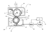
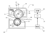
図1に本発明の第一の実施例を示す。
(First embodiment)
FIG. 1 shows a first embodiment of the present invention.
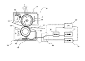
図1に示すところの1は定着ローラ、2は定着ローラ芯金、3は弾性層、4は離型層である。 In FIG. 1, 1 is a fixing roller, 2 is a fixing roller core, 3 is an elastic layer, and 4 is a release layer.
5は、加圧ローラ、6は加圧ローラ芯金、7は弾性層、8は離型層兼導電層である。 5 is a pressure roller, 6 is a pressure roller core, 7 is an elastic layer, and 8 is a release layer / conductive layer.
9はヒータ、10は温度センサー、11は分離爪、12は分離積めバネ、13は定着入り口ガイド、14は排紙ガイド、15加圧給電ブラシ、16は絶縁部材、17は給電用のリード線、18は加圧バイアス用の高圧電源、19は断熱カバー、20は定着フレーム、21は定着器、22は電流検出手段、23は制御装置、24は転写材であるところの紙である。 9 is a heater, 10 is a temperature sensor, 11 is a separation claw, 12 is a separation spring, 13 is a fixing entrance guide, 14 is a paper discharge guide, 15 pressurizing power supply brush, 16 is an insulating member, 17 is a lead wire for power supply , 18 is a high-voltage power supply for pressure bias, 19 is a heat insulating cover, 20 is a fixing frame, 21 is a fixing device, 22 is a current detecting means, 23 is a control device, and 24 is a paper as a transfer material.
定着ローラ1の外径は、50mmである。芯金2はアルミニウム製で厚みが3mmである。弾性層3はJIS硬度30°のシリコーンゴム製で厚みは、250μmである。離型層4はPFA樹脂で厚みが50μmである。定着ローラ1の外径50mm部分の軸方向長さは330mmである。
The outer diameter of the fixing
加圧ローラ5は外径が40mmである。芯金6は鉄製で外径が30mmである。弾性層7はJIS硬度30°のシリコーンゴム製で厚みは、約5mmである。離型層8は電気導電性のPFA樹脂で厚みが50μmである。離型層8の表面抵抗は、104〜108Ωであればよく、本実施例では、106Ωとした。加圧ローラ5の外径40mm部分の軸方向長さは320mmである。
The
加圧ローラ5は、不図示の加圧手段により定着ローラ1に274Nの力で当接する。
The
定着ローラ1は回転駆動しており、周速は167mm/secである。加圧ローラ5は定着ローラに従動回転する。
The fixing
この定着器21で通紙可能な紙24サイズは、幅297mmのA3サイズまでである。
The size of
定着ローラ1は内部に設けたヒータ9により加熱される。
The fixing
定着ローラ1には、温度センサー10が取り付けてあり、温度センサー10の情報を元に画像形成装置に設けた制御装置が定着ローラ1の表面が190℃になるようにヒータ9の駆動を制御する。
A
分離爪11は、定着ローラ1にと右折している先端の幅が2mmで先端部分は、主断面半径が15μmの曲面形状をしており、表面をPFA樹脂でコーティングしている。分離爪11は、分離爪バネ12により1.47Nの力で定着ローラに当接している。
The
定着ニップを通過した紙は、融けたトナーの粘性や静電気力により定着ローラ1に吸着している。
The paper that has passed through the fixing nip is attracted to the fixing
分離爪は、その紙を定着ローラから剥離する。 The separation claw peels the paper from the fixing roller.
定着入り口ガイド13は、未定着画像を載せた紙を定着ニップに導入する。
The fixing
定着排紙ガイド14は、定着後の紙を支持して搬送を安定させる。
The fixing
紙24には、不図示の画像形成手段、転写手段によりトナー像が形成されている。
A toner image is formed on the
トナー像は、一成分の磁性トナーで形成されており、トナーの帯電極性は、マイナスである。 The toner image is formed of a single component magnetic toner, and the charge polarity of the toner is negative.
加圧ローラ5の表層導電離型層8には、軸方向短部で給電ブラシ15が接触しており、電源18により通常+2000Vの電圧が印加されている。
The surface layer conductive release layer 8 of the
バイアス電源18は、0Vから+3000Vの出力が可能であり、その出力電圧は、本体制御装置23で制御する。
The
定着ローラ1の芯金2は、電気的に接地しており、定着ローラ1と加圧ローラ5の間には、通常+2000Vの電位差を設ける。
The cored
加圧バイアスは、定着ローラ1と加圧ローラ5の間に電界を形成し、紙24上のトナーを静電気的に紙に押さえつけて、定着での飛び散り、オフセット、尾引きといった画像不良を防止する。
The pressure bias forms an electric field between the fixing
飛び散りは、紙上のトナーが広がることによりにじんだようになる画像不良である。 Scattering is an image defect that becomes blurred as the toner on the paper spreads.
尾引きは、飛び散りの一種で、紙搬送方向に対して垂直方向の横線が部分的に切れたり、紙搬送方向下流側ににじんだようになる現象である。 The tailing is a kind of scattering, and is a phenomenon in which a horizontal line in a direction perpendicular to the paper transport direction is partially cut off or blots downstream in the paper transport direction.
オフセットは、定着ニップを通過したトナーが定着ローラに付着して、定着ローラの周回一周後に汚れとして紙面上に付着する現象である。 The offset is a phenomenon in which the toner that has passed through the fixing nip adheres to the fixing roller and adheres to the paper surface as dirt after one round of the fixing roller.
給電ブラシ15とバイアス電源18の間には、電流検出手段22が設けてあり、加圧ローラに流れる電流をモニターする。
A
電流検出手段22は、本体の制御装置23に接続しており、本体の制御装置は、電流検出手段22からの信号によりバイアス電源18の出力を変更する。
The current detection means 22 is connected to the
その動作を図13に沿って説明する。 The operation will be described with reference to FIG.
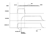
図13は、定着ニップを通過する紙と高圧電源の動作を説明する図である。同図の横軸は時間を示す。縦軸の上段は、紙の通過状況を示し、二段目は電圧を、下段は電流波形を模式的に示す。 FIG. 13 is a diagram for explaining the operation of the paper passing through the fixing nip and the high-voltage power supply. The horizontal axis of the figure shows time. The upper part of the vertical axis shows the passage of paper, the second part schematically shows the voltage, and the lower part schematically shows the current waveform.
横軸の記号Jは、紙先端位置、Kは画像先端でJからの時間は、30msである、LはJから80ms後の時間である、Mは電流が流れ終わる時間で約150msである。 The symbol J on the horizontal axis is the leading edge position of the paper, K is the leading edge of the image, and the time from J is 30 ms, L is the time after 80 ms from J, and M is the time when the current finishes flowing, which is about 150 ms.
電圧の制御は、まず紙先端に合わせて電圧を印加する。 To control the voltage, first, a voltage is applied in accordance with the leading edge of the paper.
グラフ上のkの時点30ms後に電圧が立ち上がるので、kの時点から、電流検出手段により電流値を読み取りながら、電流値が5.5μAになるように電圧値を制御する。フィードバックに要する時間は、約50msで、グラフ上Lの時間までである。 Since the voltage rises 30 ms after the time point k on the graph, the voltage value is controlled so that the current value becomes 5.5 μA from the time point k while reading the current value by the current detection means. The time required for the feedback is about 50 ms, and is the time L on the graph.
紙先端で決定した電圧値での加圧ローラへの電圧印加は、紙後端、もしくは、画像域が定着ニップを抜けるまで行う。 The voltage application to the pressure roller with the voltage value determined at the leading edge of the paper is performed until the trailing edge of the paper or the image area passes through the fixing nip.
図13においてJからKに相当する紙先端での高圧電源立ち上げ時に加圧ローラに印加する電圧は、2kVとして、その後電流値が一定になるように電圧値を変化させる。 In FIG. 13, the voltage applied to the pressure roller when the high voltage power source is started up at the leading edge of the paper corresponding to J to K is set to 2 kV, and then the voltage value is changed so that the current value becomes constant.
もしくは、前回の定着動作で加圧ローラに印加した電圧値を本体制御部に記憶させておき、高圧電源立ち上げ時には、その電圧を印加して、その後、電流値を検出ながら電圧値を制御しても良い。 Alternatively, the voltage value applied to the pressure roller in the previous fixing operation is stored in the main body control unit, and when the high-voltage power supply is turned on, the voltage is applied, and then the voltage value is controlled while detecting the current value. May be.
上記構成とした理由を以下に示す。 The reason for the above configuration is shown below.
加圧ローラに印加する電圧と、そこに流れる電流、および、紙の電位の関係を把握するための実験を以下に示す。 An experiment for grasping the relationship between the voltage applied to the pressure roller, the current flowing therethrough, and the paper potential is shown below.
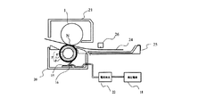
加圧ローラに定電圧を印加し、加圧ローラに流れる電流と定着ニップ前の紙電位を測定するための構成を図2に示す。 FIG. 2 shows a configuration for applying a constant voltage to the pressure roller and measuring the current flowing through the pressure roller and the paper potential before the fixing nip.
電位計には、トレック(株)製のModel.341を使用した。図2に示すところの26は、電位計の測定部である。 For the electrometer, Model. 341 was used. 2 shown in FIG. 2 is a measuring unit of the electrometer.
電位計の測定部と定着ニップの距離を仮にAとする。 Let A be the distance between the measurement part of the electrometer and the fixing nip.
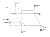
この測定系で、通紙時の加圧ローラ電流と紙電位の関係を示したのが図3である。 FIG. 3 shows the relationship between the pressure roller current and the paper potential when the paper is passed in this measurement system.
図3の上段が紙電位、下段が加圧ローラ電流である。 The upper part of FIG. 3 is the paper potential, and the lower part is the pressure roller current.
紙電位と加圧ローラ電流を同時に測定すると測定位置の違いから時間的なずれが生じる。 If the paper potential and the pressure roller current are measured simultaneously, a time lag occurs due to the difference in measurement position.
そのずれが図2で示したところのAに相当する。 The deviation corresponds to A shown in FIG.
図3は、加圧ローラに+2kV印加したときの紙電位と加圧ローラ電流の様子である。 FIG. 3 shows the paper potential and pressure roller current when +2 kV is applied to the pressure roller.
紙電位は、先端では、略0Vであるが、紙先端が定着ニップNに入った瞬間に+1.2kV程度になる。 The paper potential is approximately 0 V at the leading edge, but becomes about +1.2 kV at the moment when the leading edge enters the fixing nip N.
加圧ローラ電流は、定着ニップに紙が入った瞬間に流れるが、その後流れなくなる。 The pressure roller current flows at the moment when the paper enters the fixing nip, but then stops flowing.
電流が流れる時間は、100〜150m秒であった。 The current flow time was 100 to 150 milliseconds.
つまり、紙先端が定着ニップに入ると加圧ローラから紙に電荷が供給され電位が上昇する。 That is, when the leading edge of the paper enters the fixing nip, electric charges are supplied from the pressure roller to the paper, and the potential rises.
電位が上昇しきると電流が流れなくなる。 When the potential rises, current stops flowing.
紙先端で加圧ローラに流れる電流は、定着ローラの表面電位で変化する。 The current that flows through the pressure roller at the leading edge of the paper varies with the surface potential of the fixing roller.
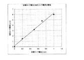
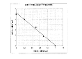
図7は、定着ローラの表面電位を変化させて測定した加圧ローラの紙先端での電流値である。 FIG. 7 is a current value at the paper tip of the pressure roller measured by changing the surface potential of the fixing roller.
定着ローラの電位が0Vの時には、5.7μAの電流が流れるのに対して、定着ローラ表面が加圧バイアスと同じ略+2kVに帯電していると電流は流れない。 When the potential of the fixing roller is 0V, a current of 5.7 μA flows. On the other hand, when the surface of the fixing roller is charged to approximately +2 kV which is the same as the pressure bias, no current flows.
これは、電位差がある定着ローラ表面と加圧ローラの間に紙が入ってくることにより、紙が充電されるからである。 This is because the paper is charged when the paper enters between the surface of the fixing roller having a potential difference and the pressure roller.
一方、定着ローラの表面電位は、通紙により上昇する傾向がる。 On the other hand, the surface potential of the fixing roller tends to increase due to paper passing.
理由は、定着ローラ1の表面を被覆するPFA樹脂に通紙により細かな傷がついたりトナーや紙紛が付着して、帯電しやすくなるからである。
The reason is that the PFA resin covering the surface of the fixing
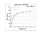
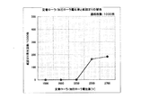
通紙枚数と定着ローラの表面電位の関係を図4に示す。 FIG. 4 shows the relationship between the number of sheets passed and the surface potential of the fixing roller.
図4の横軸は、通紙枚数、縦軸は、定着ローラの表面電位である。 In FIG. 4, the horizontal axis represents the number of sheets to be passed and the vertical axis represents the surface potential of the fixing roller.
定着ローラの電位は、初期は、略0Vであるが、通紙とともに上昇し、5万枚程度通紙すると+900V程度になる。 The initial potential of the fixing roller is about 0V, but rises with the passing of paper and reaches about + 900V when about 50,000 sheets are passed.
耐久により定着ローラの電位が上昇すると、図7に示したように、紙が定着ニップに入ったときに加圧ローラに流れる電流値は、小さくなる。 When the potential of the fixing roller rises due to durability, as shown in FIG. 7, the value of the current that flows through the pressure roller when the paper enters the fixing nip decreases.
また、定着ローラが+に帯電すると定着ローラ1と加圧ローラ5で形成する電位差が小さくなり、画像不良が発生するようになる。
Further, when the fixing roller is charged to +, the potential difference formed between the fixing
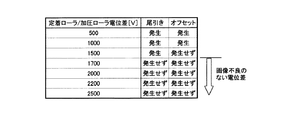
定着ローラ1と加圧ローラ5の電位差と画像の関係を図5に示す。
FIG. 5 shows the relationship between the potential difference between the fixing
オフセットを防止するのに必要な電位差は、1.5kV以上、尾引きを防止するのに必要な電位差は、1.7V以上であることを示す。 This indicates that the potential difference necessary for preventing the offset is 1.5 kV or more, and the potential difference necessary for preventing the tailing is 1.7 V or more.
耐久後にもオフセットの防止のための電位差が取れるように、加圧バイアスの電圧値を大きく設定しておくことも考えられる。 It is also conceivable that the voltage value of the pressurizing bias is set large so that a potential difference for preventing offset can be obtained even after endurance.
しかし、加圧バイアスを大きく設定しておくと、定着ローラが帯電していない初期に、紙が定着ローラ1に強く静電吸着し、紙詰まりを発生してしまうという問題もある。
However, if the pressure bias is set to a large value, there is a problem that paper is strongly attracted to the fixing
紙詰まりは、定着ローラに紙が強く静電吸着てしまうため分離爪11ではがすことができなくなり発生する。
The paper jam occurs because the paper is strongly electrostatically attracted to the fixing roller and cannot be removed by the
定着ローラと加圧ローラの電位差と紙詰まりの関係を図6に示す。 FIG. 6 shows the relationship between the potential difference between the fixing roller and the pressure roller and paper jam.
横軸は、定着ローラと加圧ローラの電位差、縦軸は、紙を1000枚通紙したときに紙詰まりが発生した回数である。 The horizontal axis represents the potential difference between the fixing roller and the pressure roller, and the vertical axis represents the number of times paper jam occurred when 1000 sheets were passed.
定着ローラ、加圧ローラの電位差が2.2kVでは、紙詰まりは発生しないが、2.5kV以上では、紙詰まりが発生する。 When the potential difference between the fixing roller and the pressure roller is 2.2 kV, no paper jam occurs. However, when the potential difference is 2.5 kV or higher, a paper jam occurs.
画像、および、紙詰まりから、定着ローラと加圧ローラの電位差は、2kV程度が適当である。 About 2 kV is appropriate for the potential difference between the fixing roller and the pressure roller due to image and paper jam.
本実施例の構成では、紙先端で加圧ローラに流れる電流が5.5μAになるように加圧バイアスを制御する。 In the configuration of this embodiment, the pressure bias is controlled so that the current flowing through the pressure roller at the front end of the paper is 5.5 μA.
この構成で通紙確認を行ったところ、加圧ローラの電圧は、定着器初期では、2kV、5万枚通紙後では、2.9kVで、耐久を通して約2kVの定着ローラ/加圧ローラ電位差を保つことができた。 When the sheet passing confirmation was performed with this configuration, the pressure roller voltage was 2 kV at the initial stage of the fixing unit and 2.9 kV after passing 50,000 sheets, and the fixing roller / pressure roller potential difference of about 2 kV through durability. Was able to keep.
また、耐久を通して、尾引きやオフセットの画像不良、分離爪での紙詰まりといった不具合の発生はなかった。 In addition, through endurance, there were no problems such as trailing or offset image defects or paper jams in the separation nails.
なお、紙先端での定着バイアスの電圧制御は、通紙ごとに行っても良いし、数枚から数十枚に一回の割合で行っても良い。 Note that the voltage control of the fixing bias at the leading edge of the paper may be performed for every sheet passing, or may be performed once every several to tens of sheets.
以上のように構成することで、定着ローラが帯電した場合でも定着ローラと加圧ローラの電位差を適正に保つことができ、耐久使用による画像不良や、紙詰まりが発生しない定着装置を構成することができる。 By configuring as described above, it is possible to maintain an appropriate potential difference between the fixing roller and the pressure roller even when the fixing roller is charged, and to form a fixing device that does not cause image defects or paper jams due to durable use. Can do.
(第2の実施例)
図8に本発明の第二の実施例を示す。
(Second embodiment)
FIG. 8 shows a second embodiment of the present invention.
図8に示すところの27は定着ローラ、28は定着ローラ芯金、29は離型層、30は加圧ローラ、31は加圧ローラ芯金、32は弾性層、33は離型層、34は高圧電源、35は分離爪を加圧するためのバネ、36は定着装置である。 8, 27 is a fixing roller, 28 is a fixing roller core, 29 is a release layer, 30 is a pressure roller, 31 is a pressure roller core, 32 is an elastic layer, 33 is a release layer, 34 Is a high-voltage power source, 35 is a spring for pressing the separation claw, and 36 is a fixing device.
定着ローラ27は外径の大きい面長部と軸受けと勘合するジャーナル部があり、面長部は外径40mm、軸方向長さは、330mmである。
The fixing
芯金28は厚みが1.5mmのアルミニウム製である。
The
表層の離型層33は厚さが20μmのPFA樹脂である。 The surface release layer 33 is a PFA resin having a thickness of 20 μm.
加圧ローラ30は、面長部とその両端にローラを支持する軸があり、面長部は、外径30mm、軸不幸長さ320mmである。
The
芯金31は、ニッケル鍍金を施した鉄製で、外径は、20mmである。 The core metal 31 is made of iron plated with nickel and has an outer diameter of 20 mm.
弾性層32は、JIS硬度30°、電気抵抗105Ωcmのシリコーンゴム製である。
The
離型層33は、導電離型層で電気抵抗105ΩcmのPFA樹脂である。 The release layer 33 is a conductive release layer and is a PFA resin having an electric resistance of 10 5 Ωcm.
定着ローラ27の内部にはヒータが設けてあり、定着ローラ27の加熱を行う。定着ローラ27の温度制御は、温度センサー10で表面温度を検出し、本体制御装置でヒータ9の駆動を制御することで行う。
A heater is provided inside the fixing
定着ローラが、190℃になるように温調制御する。 The temperature of the fixing roller is controlled so as to be 190 ° C.
加圧ローラ30は、不図示の加圧手段で176Nの力で定着ローラ27に当接する。
The
定着ローラ27の周速は、150mm/secである。加圧ローラは、定着ローラに従動回転する。
The peripheral speed of the fixing
分離爪11はバネ35で加圧され、0.3Nの力で定着ローラ27に当接する。
The
定着ローラ27の離型層29が40μm以下と小さい場合には、分離爪11による磨耗量を小さく抑えるために、当接圧を小さく本実施例のように設定する場合がある。
When the release layer 29 of the fixing
定着ローラ芯金28には、高圧電源34が接続されている。
A high
高圧電源は、−1kVから−2kVの出力が可能である。 The high voltage power supply can output from −1 kV to −2 kV.
加圧ローラ芯金31は、電流検出手段22を介して電気的に接地している。 The pressure roller core 31 is electrically grounded via the current detection means 22.
この定着装置で定着ローラに定電圧を印加して紙を通紙すると、紙先端で接地から加圧ローラに向かってプラスの電流が流れる。 When a constant voltage is applied to the fixing roller by this fixing device and a paper is passed, a positive current flows from the ground toward the pressure roller at the leading edge of the paper.
この電流は、定着ローラの表面で値が変化する。 The value of this current changes on the surface of the fixing roller.
図9に定着ローラ電位と加圧ローラ向かって流れる電流の関係を示す。 FIG. 9 shows the relationship between the fixing roller potential and the current flowing toward the pressure roller.
図9に示すグラフの横軸は、定着ローラの表面電位、縦軸は加圧ローラに流れる電流値である。 The horizontal axis of the graph shown in FIG. 9 is the surface potential of the fixing roller, and the vertical axis is the current value flowing through the pressure roller.
定着ローラの電位が−1kVの時には、加圧ローラに−6μAの電流が流れるが、定着ローラの電位が0Vの時には、電流は流れない。 When the potential of the fixing roller is −1 kV, a current of −6 μA flows through the pressure roller. However, when the potential of the fixing roller is 0 V, no current flows.
定着ローラ表面電位は、芯金28に印加した電圧と離型層29の帯電の合計である。
The surface potential of the fixing roller is the sum of the voltage applied to the
芯金に−1kV印加していても、耐久使用により離型層29が+500Vに帯電すると定着ローラの表面電位は、表面の帯電電位により相殺されて−500Vに小さくなる。 Even when −1 kV is applied to the core metal, when the release layer 29 is charged to +500 V due to durable use, the surface potential of the fixing roller is offset by the charged potential of the surface and becomes −500 V.
定着ローラの表面電位が小さくなると尾引きやオフセットといった画像不良が発生する。 When the surface potential of the fixing roller becomes small, image defects such as tailing and offset occur.
一方、耐久使用による離型層29の帯電を見越して定着バイアスの電圧を大きめに設定しておくと、初期に定着ローラ27の表面電位が大きくなりすぎ、紙が静電吸着するようになる。すると、本実施例のように分離爪11を20gf以下の小さい力で定着ローラに当接させている場合には、分離爪11に紙先端が引っかかって紙詰まりが発生するようになる。
On the other hand, if the voltage of the fixing bias is set to a large value in anticipation of the charging of the release layer 29 due to durable use, the surface potential of the fixing
本実施例での適正な定着ローラの表面電位は、−1kVである。 The proper surface potential of the fixing roller in this embodiment is −1 kV.
定着ローラ27の表面電位が−1kVのときに紙先端で加圧ローラに流れる電流は、6μAである。
When the surface potential of the fixing
本実施例では、この適正な定着ローラ電位を耐久を維持するために紙先端で加圧ローラに流れる電流が6μAになるように定着ローラ芯金に印加する電圧を制御する。 In this embodiment, in order to maintain the proper fixing roller potential, the voltage applied to the fixing roller mandrel is controlled so that the current flowing to the pressure roller at the front end of the paper is 6 μA.
この構成で、耐久を行ったところ、定着ローラ芯金28に印加する電圧は初期は、−1kVであったが、5万枚通紙後は、−1.5kVであった。
When durability was performed with this configuration, the voltage applied to the fixing
これにより、定着ローラの表面電位は耐久をとおして−1kVであり、オフセット/尾引きといった画像不良や紙詰まりの発生もなかった。 As a result, the surface potential of the fixing roller was −1 kV throughout the endurance, and there were no image defects such as offset / tailing and paper jams.
以上のように構成することで、定着ローラに電圧を印加する定着装置においても定着ローラの表面離型層の帯電による画像不良を、定着バイアスアップの弊害である紙詰まりを伴うことなく改善することができる。 With the configuration described above, even in a fixing device that applies a voltage to the fixing roller, image defects due to charging of the surface release layer of the fixing roller can be improved without causing a paper jam that is an adverse effect of increasing the fixing bias. Can do.
(第3の実施例)
図11に本発明の第三の実施例を示す。
(Third embodiment)
FIG. 11 shows a third embodiment of the present invention.
本実施例では、高速の定着装置の場合を示す。 In this embodiment, a case of a high-speed fixing device is shown.
図11の定着装置は、定着ローラの周速が300mm/sでA4サイズの紙を毎分60枚定着可能な定着装置である。 The fixing device of FIG. 11 is a fixing device capable of fixing 60 sheets of A4 size paper per minute with a peripheral speed of the fixing roller of 300 mm / s.
図11に示すところの36は定着装置、1は定着ローラ、2は定着ローラ芯金、3は弾性層、4は離型層である。 11, 36 is a fixing device, 1 is a fixing roller, 2 is a fixing roller core, 3 is an elastic layer, and 4 is a release layer.
5は加圧ローラ、6は加圧ローラ芯金、7は弾性層、8は離型層兼導電層である。
9はヒータ、10は温度センサー、11は分離爪、12は分離積めバネ、13は定着入り口ガイド、14は排紙ガイド、15加圧給電ブラシ、16は絶縁部材、17は給電用のリード線、18は加圧バイアス用の高圧電源、19は断熱カバー、20は定着フレーム、24は転写材であるところの紙である。 9 is a heater, 10 is a temperature sensor, 11 is a separation claw, 12 is a separation stack spring, 13 is a fixing entrance guide, 14 is a discharge guide, 15 is a pressurized power supply brush, 16 is an insulating member, and 17 is a lead wire for power supply. , 18 is a high-voltage power supply for pressure bias, 19 is a heat insulating cover, 20 is a fixing frame, and 24 is a paper as a transfer material.
定着ローラ1の外径は、50mmである。芯金2はアルミニウム製で厚みが3mmである。弾性層3はJIS硬度30°のシリコーンゴム製で厚みは、250μmである。離型層4はPFA樹脂で厚みが50μmである。定着ローラ1の外径50mm部分の軸方向長さは330mmである。
The outer diameter of the fixing
加圧ローラ5は外径が40mmである。芯金6は鉄製で外径が30mmである。弾性層7はJIS硬度30°のシリコーンゴム製で厚みは、約5mmである。離型層8は電気導電性のPFA樹脂で厚みが50μmである。離型層8の表面抵抗は、104〜108Ωであればよく、本実施例では、106Ωとした。加圧ローラ5の外径40mm部分の軸方向長さは320mmである。
The
加圧ローラ5は、不図示の加圧手段により定着ローラ1に637Nの力で当接する。
The
図11に示すところの37は定電流電源、38は電圧検知手段、39は定電圧電源、40は電圧切替え装置である。 11, 37 is a constant current power source, 38 is a voltage detecting means, 39 is a constant voltage power source, and 40 is a voltage switching device.
定電流電源37の定電流値は、6μAである。定電流電源37は0Vから3kVの電圧出力が可能で、0Vから3kVまでの立ち上がり時間は、15msである。
The constant current value of the constant
電圧検出手段38は、定電流電源37が発生した電圧を検出して本体制御部23に信号を送る。
The voltage detection means 38 detects the voltage generated by the constant
定電圧電源39は、本体制御部23からの信号により、電圧値が変更可能な電源である。出力可能な電圧範囲は、2kVから3kVで出力電圧を安定させるために立ち上がりは、若干遅く80msとしている。
The constant
電圧切替え装置40は、本体制御装置23の信号により、加圧ローラ5に印加するバイアスを定電流電源37か定電圧電源39か、もしくは両方印加するかを切り替える。
The
次に、本実施例の定着装置の動作を図12に沿って説明する。 Next, the operation of the fixing device of this embodiment will be described with reference to FIG.
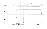
図12は、加圧ローラに印加するバイアスを定着ニップNを紙が通過するタイミングと合わせて示したものである。 FIG. 12 shows the bias applied to the pressure roller together with the timing at which the paper passes through the fixing nip N.
図12の横軸は、時間経過を示す。 The horizontal axis of FIG. 12 shows the passage of time.
図12の上段は、定着ニップを紙が通過する時間を示したものである。 The upper part of FIG. 12 shows the time for the paper to pass through the fixing nip.
二段目は、定電流電源37のバイアス印加タイミングを示す。
The second row shows the bias application timing of the constant
三段目は、定電圧電源39が発生する電圧値をしめす。
The third level indicates the voltage value generated by the constant
下段は、加圧ローラに印加される合成電圧を示す。 The lower row shows the combined voltage applied to the pressure roller.
本実施例の動作を説明すると、まず、紙の先端位置で定電流バイアスを印加する。定電流バイアスを印加する時間は、150msである。 The operation of this embodiment will be described. First, a constant current bias is applied at the leading end position of the paper. The time for applying the constant current bias is 150 ms.
画像の先端マージンは、一般的には、5mm以上なので、紙搬送スピードが300mm/sの本実施例の場合、紙先端がニップに到達した17ms後に画像がニップに到達する。
Since the leading edge margin of the image is generally 5 mm or more, in the case of this embodiment in which the paper conveyance speed is 300 mm / s, the image reaches the
定電流電源37の立ち上がりは、15msなので画像先端からバイアスを作用させることが出来、画像不良の発生を防止することが出来る。
Since the rising of the constant
定電流バイアスを印加し始めた最初の70msで電圧値を検出する。 The voltage value is detected in the first 70 ms when the constant current bias is applied.
電圧値を読み取ったところで、その電圧を出力するように定電圧電源を駆動する。 When the voltage value is read, the constant voltage power source is driven so as to output the voltage.
定電圧電源は、電圧が立ち上がるまでに80ms程度要するが立ち上がる間も定電流電源によりバイアスが印加されているので尾引き等の画像不良は、発生しない。 The constant voltage power supply requires about 80 ms until the voltage rises, but since the bias is applied by the constant current power supply even during the rise, image defects such as tailing do not occur.
また、紙への充電が終わるまでに定電流バイアスの印加を終了するので、大きな電圧を印加しすぎることもない。 Further, since the application of the constant current bias is completed before the charging of the paper is completed, a large voltage is not applied excessively.
以上のように構成することで、紙の先端から後端まで、尾引き防止に必要なバイアスを加圧ローラに印加することが出来、しかも紙の充電が終わるまでに定電流バイアスの印加を終了するので、必要以上に大きな電圧を印加することもない。 By configuring as described above, a bias necessary for preventing tailing can be applied to the pressure roller from the leading edge to the trailing edge of the paper, and the application of the constant current bias is completed before the charging of the paper is completed. Therefore, a voltage larger than necessary is not applied.
この構成で、5万枚の通紙試験を行ったところ、加圧ローラの電圧は、定着器初期では、2kV、5万枚通紙後では、2.9kVで、耐久を通して約2kVの定着ローラ/加圧ローラ電位差を保つことができた。 With this configuration, a 50,000 sheet passing test was conducted. The voltage of the pressure roller was 2 kV at the initial stage of the fixing device, 2.9 kV after passing 50,000 sheets, and the fixing roller of about 2 kV throughout the durability. / Pressure roller potential difference could be maintained.
また、耐久を通して、尾引きやオフセットの画像不良、分離爪での紙詰まりといった不具合の発生はなかった。 In addition, through endurance, there were no problems such as trailing or offset image defects or paper jams in the separation nails.
なお、紙先端での定電流バイアス印加による加圧バイアス電圧制御は、通紙ごとに行っても良いし、数枚から数十枚に一回の割合で行っても良い。 The pressurizing bias voltage control by applying a constant current bias at the leading edge of the paper may be performed for every sheet passing, or may be performed once every several to several tens of sheets.
この場合、電圧決定を行わない定着動作時は、加圧ローラには、前の定電流印加時に決定した電圧値を印加するようにする。 In this case, during the fixing operation in which the voltage is not determined, the voltage value determined when the constant current is applied is applied to the pressure roller.
1 定着ローラ
5 加圧ローラ
18 高圧電源(バイアス電源)
34 高圧電源
39 定電圧電源
22 電流検出手段
37 定電流電源
38 電圧検出手段
39 定電圧電源
DESCRIPTION OF
34 High
Claims (3)
加圧ローラへのバイアス手段として電圧値の変更が可能な定電圧電源を設けており、かつ、その定電圧電源から加圧ローラに流れる電流を検出する電流検出手段を設けており、転写材先端がローラ対で形成するニップに突入したときに加圧ローラに流れる電流値が所定の値になるように加圧ローラに印加する電圧値を制御することを特徴とする定着装置。 This is a fixing device in which a transfer material on which an unfixed toner image is placed is nipped and conveyed by a pair of rollers composed of a heat-pressed fixing roller and a pressure roller, and the toner image is fixed on the transfer material by heating and melting. In the fixing device having a conductive release layer on the pressure roller surface and applying a bias to the conductive layer,
A constant voltage power source capable of changing the voltage value is provided as a bias means for the pressure roller, and a current detection means for detecting a current flowing from the constant voltage power source to the pressure roller is provided. A fixing device that controls a voltage value applied to the pressure roller so that a current value flowing through the pressure roller becomes a predetermined value when entering the nip formed by the roller pair.
定着ローラは、金属芯金の上に絶縁性の離型層を有しており、その金属芯金にバイアスを印加し、また、加圧ローラ表面には導電性の離型層を有する定着装置において、
定着ローラ芯金へのバイアス手段として電圧値の変更が可能な定電圧電源を設けており、また、加圧ローラ表面は、電気的に接地されており、加圧ローラに流れる電流値を検出する電流検出手段を設けており、転写材先端がローラ対で形成するニップに突入したときに加圧ローラに流れる電流値が所定の値になるように定着ローラに印加する電圧値を制御することを特徴とする定着装置。 This is a fixing device in which a transfer material on which an unfixed toner image is placed is nipped and conveyed by a pair of rollers composed of a heat-pressed fixing roller and a pressure roller, and the toner image is fixed on the transfer material by heating and melting. And
The fixing roller has an insulating release layer on the metal core, applies a bias to the metal core, and has a conductive release layer on the surface of the pressure roller. In
A constant voltage power source capable of changing the voltage value is provided as a bias means for the fixing roller core, and the pressure roller surface is electrically grounded to detect the value of the current flowing through the pressure roller. Current detection means is provided to control the voltage value applied to the fixing roller so that the current value flowing through the pressure roller becomes a predetermined value when the leading edge of the transfer material enters the nip formed by the roller pair. A fixing device characterized.
加圧ローラへのバイアス手段として定電流電源と、電圧値の変更が可能な定電圧電源を設けており、かつ、定電流電源には、発生した電圧値を検出するための電圧検出手段が設けてあって、
転写材先端がローラ対で形成するニップに突入したときには加圧ローラには、定電流電源からバイアスを印加し、その後、定電圧電源のバイアス印加に切り替え、定電圧電源で印加する電圧値は、定電流電源でバイアスを印加した際に発生した電圧を元にしていることを特徴とする定着装置。 This is a fixing device in which a transfer material on which an unfixed toner image is placed is nipped and conveyed by a pair of rollers composed of a heat-pressed fixing roller and a pressure roller, and the toner image is fixed on the transfer material by heating and melting. In the fixing device having a conductive release layer on the pressure roller surface and applying a bias to the conductive layer,
A constant current power supply and a constant voltage power supply capable of changing the voltage value are provided as bias means for the pressure roller, and the constant current power supply is provided with a voltage detection means for detecting the generated voltage value. Because
When the leading edge of the transfer material enters the nip formed by a pair of rollers, a bias is applied to the pressure roller from a constant current power source, and then the bias voltage is switched to a constant voltage power source. A fixing device based on a voltage generated when a bias is applied by a constant current power source.
Priority Applications (1)
| Application Number | Priority Date | Filing Date | Title |
|---|---|---|---|
| JP2004110885A JP2005292689A (en) | 2004-04-05 | 2004-04-05 | Fixing device |
Applications Claiming Priority (1)
| Application Number | Priority Date | Filing Date | Title |
|---|---|---|---|
| JP2004110885A JP2005292689A (en) | 2004-04-05 | 2004-04-05 | Fixing device |
Publications (1)
| Publication Number | Publication Date |
|---|---|
| JP2005292689A true JP2005292689A (en) | 2005-10-20 |
Family
ID=35325642
Family Applications (1)
| Application Number | Title | Priority Date | Filing Date |
|---|---|---|---|
| JP2004110885A Withdrawn JP2005292689A (en) | 2004-04-05 | 2004-04-05 | Fixing device |
Country Status (1)
| Country | Link |
|---|---|
| JP (1) | JP2005292689A (en) |
Cited By (3)
| Publication number | Priority date | Publication date | Assignee | Title |
|---|---|---|---|---|
| JP2013097165A (en) * | 2011-10-31 | 2013-05-20 | Kyocera Document Solutions Inc | Image forming apparatus |
| JP2017219790A (en) * | 2016-06-10 | 2017-12-14 | 京セラドキュメントソリューションズ株式会社 | Image forming apparatus |
| US10078297B2 (en) | 2014-11-13 | 2018-09-18 | Canon Kabushiki Kaisha | Image forming apparatus |
-
2004
- 2004-04-05 JP JP2004110885A patent/JP2005292689A/en not_active Withdrawn
Cited By (3)
| Publication number | Priority date | Publication date | Assignee | Title |
|---|---|---|---|---|
| JP2013097165A (en) * | 2011-10-31 | 2013-05-20 | Kyocera Document Solutions Inc | Image forming apparatus |
| US10078297B2 (en) | 2014-11-13 | 2018-09-18 | Canon Kabushiki Kaisha | Image forming apparatus |
| JP2017219790A (en) * | 2016-06-10 | 2017-12-14 | 京セラドキュメントソリューションズ株式会社 | Image forming apparatus |
Similar Documents
| Publication | Publication Date | Title |
|---|---|---|
| JP4099098B2 (en) | Fixing device and image forming device | |
| JP4478342B2 (en) | Fixing device | |
| JP6410512B2 (en) | Image forming apparatus | |
| JP3990957B2 (en) | Heat fixing device | |
| JP2004157279A (en) | Heat fixing device | |
| JP2006047556A (en) | Fixing device for image forming apparatus | |
| JP5153249B2 (en) | Image forming apparatus | |
| JP2006036424A (en) | Sheet material identification apparatus, heating apparatus using the same, and image forming apparatus | |
| JP4378162B2 (en) | Sheet identifying apparatus and image forming apparatus having the same | |
| US6560437B2 (en) | Image forming apparatus with second power source for charge elimination means | |
| JP2010191068A (en) | Image forming apparatus | |
| JPH0836329A (en) | Image forming device | |
| JP2008209459A (en) | PRESSURE MEMBER AND IMAGE HEATING DEVICE HAVING THE PRESSURE MEMBER | |
| JP3950768B2 (en) | Heat fixing device and image forming apparatus | |
| JP2003084586A (en) | Image forming device | |
| JP2017223864A (en) | Transfer roller and image forming apparatus | |
| JP2000321901A (en) | Heat fixing device and image forming device | |
| JP4164304B2 (en) | Image forming apparatus | |
| JP2017054055A (en) | Image forming apparatus | |
| JP2006091451A (en) | Heat fixing device | |
| JP4950576B2 (en) | Fixing device | |
| JP4834247B2 (en) | Fixing device | |
| JP2016188885A (en) | Image forming apparatus | |
| JPH05273879A (en) | Fixing device | |
| JP2005258041A (en) | Fixing device and image forming apparatus |
Legal Events
| Date | Code | Title | Description |
|---|---|---|---|
| A300 | Withdrawal of application because of no request for examination |
Free format text: JAPANESE INTERMEDIATE CODE: A300 Effective date: 20070605 |