JP2005292634A - Image forming apparatus drive unit and image forming apparatus - Google Patents
Image forming apparatus drive unit and image forming apparatus Download PDFInfo
- Publication number
- JP2005292634A JP2005292634A JP2004110055A JP2004110055A JP2005292634A JP 2005292634 A JP2005292634 A JP 2005292634A JP 2004110055 A JP2004110055 A JP 2004110055A JP 2004110055 A JP2004110055 A JP 2004110055A JP 2005292634 A JP2005292634 A JP 2005292634A
- Authority
- JP
- Japan
- Prior art keywords
- drive transmission
- drive
- unit
- gear
- image forming
- Prior art date
- Legal status (The legal status is an assumption and is not a legal conclusion. Google has not performed a legal analysis and makes no representation as to the accuracy of the status listed.)
- Withdrawn
Links
Images


Landscapes
- Electrophotography Configuration And Component (AREA)
- Gears, Cams (AREA)
Abstract
【課題】 色ずれ等の画像不良を防止し、高画質化を実現させた画像形成装置の駆動ユニット及び画像形成装置を提供する。
【解決手段】 感光体ドラム1に接続されるドラム駆動ギア48と噛合う中間ギア47のギア歯面をクラウニング形状とし、この中間ギア47を、その曲げ弾性率がドラム駆動ギア48を形成している樹脂の曲げ弾性率の60%以下の樹脂部材にて構成する。
【選択図】 図4
PROBLEM TO BE SOLVED: To provide an image forming apparatus drive unit and an image forming apparatus which prevent image defects such as color misregistration and realize high image quality.
SOLUTION: A gear tooth surface of an intermediate gear 47 that meshes with a drum drive gear 48 connected to a photosensitive drum 1 is formed in a crowning shape, and the bending elastic modulus of the intermediate gear 47 forms a drum drive gear 48. It is comprised with the resin member of 60% or less of the bending elastic modulus of the resin which is.
[Selection] Figure 4
Description
本発明は、シート等の記録媒体上に画像を形成する機能を備えた、例えば、複写機、プリンタ、あるいは、ファクシミリ装置などの画像形成装置に関し、特に、画像形成装置の駆動ユニットに関するものである。 The present invention relates to an image forming apparatus having a function of forming an image on a recording medium such as a sheet, such as a copying machine, a printer, or a facsimile machine, and more particularly to a drive unit of the image forming apparatus. .
近年、カラー画像の形成を行うことができるカラー電子写真画像形成装置の需要が増大しており、(1)低ランニングコスト(2)小スペース(3)低電力(4)高画質(5)ハイスピード(6)操作性の向上の6項目が達成できるカラー画像形成装置の投入が期待されている。 In recent years, the demand for color electrophotographic image forming apparatuses capable of forming color images has increased. (1) Low running cost (2) Small space (3) Low power (4) High image quality (5) High It is expected to introduce a color image forming apparatus capable of achieving six items of speed (6) improvement in operability.
その中で、(6)操作性を簡易にしながら、(5)ハイスピード化を図り、かつ、(4)高画質のカラー画像を提供する技術を提供する方式として、カラー画像形成装置にイエロー、マゼンダ、シアン、ブラックの4色のプロセスカートリッジを用いて、感光体ドラムを4つ並列に並べ画像形成を行い、操作性の向上、ハイスピード化を図る方式がある。この方式をタンデム式、又は、4ドラム方式カラー画像形成装置と呼ぶ。 Among them, (6) while simplifying operability, (5) high speed and (4) a technique for providing a high-quality color image, a color image forming apparatus is provided with yellow, There is a system that uses four process cartridges of magenta, cyan, and black to form four photosensitive drums in parallel to form an image, thereby improving operability and increasing the speed. This system is called a tandem or 4-drum system color image forming apparatus.
この方式においても(4)高画質化を妨げる要因として、感光体ドラムを駆動する駆動ギア列が噛み合う事により発生する微小振動によって、感光体ドラムの回転ムラが生じ、画像上にピッチムラとなって現れるという問題がある。 Even in this method, (4) as a factor that hinders high image quality, rotation of the photosensitive drum is caused by minute vibration generated by meshing of the drive gear train that drives the photosensitive drum, resulting in pitch unevenness on the image. There is a problem of appearing.
これに対しては、例えば特許文献1に示されている様に感光体ドラムを駆動する駆動ギアを大径にして画像上に発生するピッチムラのピッチを小さくしたり、感光体ドラムを駆動する駆動ギア列の減速段数を1段にする事で発生する噛み合い周波数を1つに限定してピッチムラを目立ち難くする等の改善方法があった。
In response to this, for example, as shown in
さらに、(4)高画質化を妨げる要因として、4つの感光体ドラムとそれに対応する4つの露光手段との位置精度の悪化によって、各色ごとの走査方向の位置ズレが生じ、4色重ねた際に画像上に色ズレとなって現れるという問題がある。これに対しては、4つの感光体ドラムと4つの露光手段の全てを画像形成装置本体の両側板にて位置決めし、各々のユニット間で発生する相互位置誤差を最小限に抑える等の改善方法がある。
しかしながら、上記のような従来技術の場合には、下記のような問題が生じていた。 However, in the case of the prior art as described above, the following problems have occurred.
従来のギア構成は、根本的なピッチムラの発生要因を軽減するものではなく、発生するピッチムラを目立ち難くする効果を狙っているので、感光体ドラムの負荷変動による回転ムラや本体寿命末期の耐久劣化による噛み合い振動の増大によって画像上にレベルの悪いピッチムラが発生するおそれがある。 The conventional gear configuration does not reduce the fundamental causes of pitch unevenness, but aims to make the generated pitch unevenness inconspicuous. There is a risk that pitch unevenness with a low level may occur on the image due to an increase in the meshing vibration caused by.
大径ギア構成は、初期のピッチムラを目立ち難くする効果を発揮するが、単に画像上に発生するピッチムラのピッチを小さく(ギアの噛み合い周波数を大きく)して、従来の画像観察距離における可視感度以下にする事を目的としているので、より高画質になりカラー写真画像等を出力可能となった画像形成装置においては、ユーザーは出力されたカラー写真画像を手にとって従来の画像観察距離よりも近い観察距離で出力画像を判断する機会
が多くなる為、従来の構成で可視感度以下とされていたピッチ(周波数)であってもユーザーに悪い印象を与えてしまうことが懸念される。
The large-diameter gear configuration has the effect of making the initial pitch unevenness inconspicuous, but simply reduces the pitch unevenness generated on the image (increases the gear meshing frequency) and is less than the visible sensitivity at the conventional image observation distance. Therefore, in an image forming apparatus that has higher image quality and can output color photographic images, etc., the user can view the output color photographic image by hand and observe closer than the conventional image observation distance. Since there are many opportunities to judge the output image by distance, there is a concern that a bad impression may be given to the user even at a pitch (frequency) that is lower than the visual sensitivity in the conventional configuration.
また、1段減速構成は、減速比を稼ぐ為にモーター等の駆動源の回転金属シャフトに直接歯切りをおこなって歯数をなるべく小さくする構成をとる場合があるが、この場合、金属ギアとモールド大径ギアとが直接噛み合う事になる為、画像形成装置の本体寿命末期においては、モールド大径ギアの歯面が耐久により摩耗し、ギアの噛み合いによる振動が増大して、ピッチムラのレベルが悪化してしまうおそれがある。 In addition, the one-stage reduction configuration may take a configuration in which the number of teeth is reduced as much as possible by directly cutting the rotating metal shaft of the drive source such as a motor in order to increase the reduction ratio. Since the large gear of the mold is directly meshed, at the end of the main body life of the image forming apparatus, the tooth surface of the molded large gear is worn due to durability, the vibration due to the meshing of the gear increases, and the level of pitch unevenness is increased. There is a risk of getting worse.
図10は従来技術に係る画像形成装置の要部の概略断面図である。 FIG. 10 is a schematic cross-sectional view of a main part of an image forming apparatus according to the prior art.
さらに、露光手段との位置ズレによって発生する走査方向の色ズレを最小限に抑える為に感光体ドラム1Aを画像形成装置本体の両側板(101A)によって位置決めする本体構成とした際には、感光体ドラム1Aへの回転駆動を感光体ドラム1Aと一直線上に配置した感光体駆動ギア48Aに設けたカップリング52Aを介した伝達構成とした場合、感光体駆動ギア48Aは一方を感光体ドラム1Aによって位置決めされると共に、他方を本体駆動ユニット(の軸受け51A)によって位置決めされる事になって、感光体駆動ギア48Aの位置精度の低下を招き、その上流側相手ギア46Aとのアライメントが極端に悪化してしまうおそれがある。その際には、感光体駆動ギア48Aの噛合い時の振動が増大してピッチムラのレベルが悪化し画像品質が劣するという問題が発生してしまう。このようにアライメントが悪化してしまうと、大径ギア構成や1段減速構成を採用してもピッチムラレベル改善の効果を得ることは困難である。
Further, when the
本発明は上記の従来技術の課題を解決するためになされたもので、その目的とするところは、色ずれ等の画像不良を防止し、高画質化を実現させた画像形成装置の駆動ユニット及び画像形成装置を提供することにある。 The present invention has been made to solve the above-described problems of the prior art, and an object of the present invention is to prevent image defects such as color misregistration and achieve a high image quality and a drive unit for an image forming apparatus. An object is to provide an image forming apparatus.
上記目的を達成するために本発明にあっては、
第1駆動伝達手段と、
前記第1駆動伝達手段に接触して、該第1駆動伝達手段からの駆動力を被駆動伝達部に伝達する第2駆動伝達手段と、
を備えた画像形成装置の駆動ユニットにおいて、
前記第1駆動伝達手段及び前記第2駆動伝達手段のうち少なくとも一方に、該第1駆動伝達手段が駆動力を伝達するために該第2駆動伝達手段に接触したときの振動を抑制する振動抑制部を設けたことを特徴とする。
In order to achieve the above object, the present invention provides:
First drive transmission means;
A second drive transmission means for contacting the first drive transmission means and transmitting the driving force from the first drive transmission means to the driven transmission section;
In the drive unit of the image forming apparatus provided with
Vibration suppression that suppresses vibration when the first drive transmission means contacts the second drive transmission means to transmit the driving force to at least one of the first drive transmission means and the second drive transmission means. A feature is provided.
また、画像形成装置にあっては、
上記記載の画像形成装置の駆動ユニットと、
前記駆動ユニットに接続することにより駆動力が伝達される像担持体と、
を備えることを特徴とする。
In the image forming apparatus,
A drive unit of the image forming apparatus described above;
An image carrier to which driving force is transmitted by being connected to the driving unit;
It is characterized by providing.
以上説明したように、本発明によれば、色ずれ等の画像不良を防止し、高画質化を実現させた画像形成装置の駆動ユニット及び画像形成装置を提供することが可能となる。 As described above, according to the present invention, it is possible to provide a drive unit and an image forming apparatus for an image forming apparatus that prevent image defects such as color misregistration and realize high image quality.
以下に図面を参照して、この発明の好適な実施の形態を例示的に詳しく説明する。ただし、この実施の形態に記載されている構成部品の寸法、材質、形状それらの相対配置などは、発明が適用される装置の構成や各種条件により適宜変更されるべきものであり、この
発明の範囲を以下の実施の形態に限定する趣旨のものではない。
Exemplary embodiments of the present invention will be described in detail below with reference to the drawings. However, the dimensions, materials, shapes, and relative arrangements of the components described in this embodiment should be appropriately changed according to the configuration of the apparatus to which the invention is applied and various conditions. It is not intended to limit the scope to the following embodiments.
(画像形成装置の全体の説明)
図1は本発明の実施の形態に係る画像形成装置の概略を示す断面図である。
(Overall description of image forming apparatus)
FIG. 1 is a cross-sectional view schematically showing an image forming apparatus according to an embodiment of the present invention.
図1に示す画像形成装置は、被駆動伝達部として4個の感光体ドラム(像担持体)1(1a,1b,1c,1d)を備えており、それぞれの感光体ドラム1の周囲には、その回転方向に従って順に、感光体ドラム1表面を均一に帯電する帯電手段2(2a,2b,2c,2d)、画像情報に基づいてレーザービームを照射し感光体ドラム1上の静電潜像を形成する露光手段3(3a,3b,3c,3d)、静電潜像にトナーを付着させてトナー像として顕像化する現像手段4(トナー収納部4a1,4b1,4c1,4d1、現像ローラ4a2,4b2,4c2,4d2等から構成される)、感光体ドラム1上のトナー像を転写材に転写させる転写手段(転写ローラ)5(5a,5b,5c,5d)、転写後の感光体ドラム1表面に残った転写後トナーを除去するクリーニング手段6(6a,6b,6c,6d)等が配設されて画像形成手段(画像形成部)が構成されている。
The image forming apparatus shown in FIG. 1 includes four photosensitive drums (image carriers) 1 (1a, 1b, 1c, 1d) as driven transmission portions, and around each
ここで、感光体ドラム1と帯電手段2、現像手段4、トナーを除去するクリーニング手段6は一体的にカートリッジ化されプロセスカートリッジ7(7a,7b,7c,7d)を形成している。
Here, the
また、給送部8から給送された転写材Sは搬送ベルトで構成した搬送手段9によって前記画像形成手段へ搬送され、各色トナー像が順次転写されてカラー画像が記録された後、定着手段10で画像定着されて排出ローラ対11,12によって排出部13へ排出される。
Further, the transfer material S fed from the feeding unit 8 is conveyed to the image forming unit by a conveying
また、両面印字の際は、定着部10で転写材Sが定着されて排紙ローラ11,12によって排紙される前に、排紙ローラ11,12を逆転することにより、両面搬送経路15に搬送される(矢印A方向)。両面搬送経路15に搬送された転写材Sは、装置本体正面にある斜送ローラ16を通過し、Uターンローラ17まで垂直下方向に搬送され、Uターンローラ17及びレジストローラ8dによって画像形成部まで搬送される。
In double-sided printing, before the transfer material S is fixed by the
次に各部の構成について順次説明する。 Next, the configuration of each unit will be described sequentially.
(給送部)
給送部8は、給紙カセット8a、マルチ給紙トレイ8b、マルチ給送部8cおよびレジストローラ8dから構成されている。
(Feeding department)
The feeding unit 8 includes a
給紙カセット8aは複数枚の転写材Sを収納し、装置本体内底部に装填される。給紙カセット8aからの画像形成時には、カセットピックアップローラ8a1によって一枚づつ転写材Sが分離搬送され、カセット搬送ローラ8a2及びレジストローラ8dによって画像形成部まで搬送される。
The
マルチ給紙トレイ8bは、通常は装置本体正面に格納されているが、使用時に装置本体からマルチ給紙トレイ8bを回動して開き、複数枚の転写材Sをセットする。マルチ給紙トレイ8bからの画像形成時には、マルチピックアップローラ8c1によって一枚づつ転写材Sが分離搬送され、マルチ搬送ローラ8c2及びレジストローラ8dによって画像形成部まで搬送される。
The multi-feed tray 8b is normally stored in front of the apparatus main body, but when used, the multi-feed tray 8b is rotated and opened from the apparatus main body, and a plurality of transfer materials S are set. At the time of image formation from the multi-feed tray 8b, the transfer material S is separated and conveyed one by one by the multi-pickup roller 8c1, and conveyed to the image forming unit by the multi-conveying roller 8c2 and the
給紙カセット8a、マルチ給送部8cにおける用紙の分離や搬送は、給送部にある不図示の給紙モータによりギア駆動列を介して行われる。
Separation and conveyance of paper in the
(画像形成構成)
像担持体としての感光体ドラム1は、アルミニウム製シリンダの外周面に有機光導伝体層(OPC)を塗布して構成したものである。感光体ドラム1は、その両端部をフランジによって回転自在に支持されており、一方の端部に不図示の駆動モータから駆動力を伝達することにより、反時計周り矢印方向に回転駆動される。
(Image formation configuration)
The
各帯電手段2は、ローラ状に形成された導電性ローラで、このローラを感光体ドラム1表面に当接させるとともに、不図示の電源によって帯電バイアス電圧を印加することにより、感光体ドラム1表面を一様に帯電させるものである。
Each charging means 2 is a conductive roller formed in the shape of a roller. The roller is brought into contact with the surface of the
露光手段3は、ポリゴンミラーを有し、このポリゴンミラーにはレーザーダイオード(不図示)から画像信号に対応する画像光が照射される。 The exposure means 3 has a polygon mirror, and this polygon mirror is irradiated with image light corresponding to an image signal from a laser diode (not shown).
現像手段4は、それぞれブラック、シアン、マゼンタ、イエローの各色のトナーを収納したトナー収納部4a1,4b1,4c1,4d1、感光体表面に隣接し、不図示の駆動部により回転駆動されると共に、図示しない現像バイアス電源により現像バイアス電圧を印加することにより現像を行う現像ローラ4a2,4b2,4c2,4d2等から構成される。 The developing means 4 is adjacent to the toner storage portions 4a1, 4b1, 4c1, 4d1 that store toners of black, cyan, magenta, and yellow, respectively, and is driven to rotate by a drive unit (not shown). It comprises developing rollers 4a2, 4b2, 4c2, 4d2, etc. that perform development by applying a developing bias voltage from a developing bias power source (not shown).
また、後述する転写搬送ベルト9aの内側には、4個の感光体ドラム1a,1b,1c,1dに対向して転写搬送ベルト9aに当接する転写部材5a,5b,5c,5dがそれぞれ併設されている。これら転写部材5は不図示の転写バイアス用電源で接続されており、転写部材5から正極性の電荷が転写搬送ベルト9aを介して転写材に印加され、この電界により、感光体ドラム1に接触中の転写材に、感光体ドラム1上の負極性の各色トナー像が順次転写され、カラー画像が形成される。
In addition,
(転写材搬送構成)
転写材Sは給送部8から搬送手段9によって画像形成領域に搬送される。
(Transfer material transfer configuration)
The transfer material S is conveyed from the feeding unit 8 to the image forming area by the conveying
搬送手段9を構成する転写材担持体としての転写搬送ベルト9aは、駆動ローラ9bと従動ローラ9c,9d,9eの4本のローラで張架支持され、すべての感光体ドラム1a,1b,1c,1dに対向し配設されている。
A
そして、転写搬送ベルト9aは、感光体ドラム1に対向する外周面に転写材Sを静電吸着して上記感光体ドラム1に転写材を接触させるべく駆動ローラ9bによって循環移動する。これにより、転写材は転写搬送ベルト9aにより転写位置まで搬送され、感光体ドラム1上のトナー像が転写される。
The
また、転写搬送ベルト9aの最上流位置には、該ベルト9aとともに転写材を挟持し、且つ転写材を転写搬送ベルト9aに吸着させる吸着ローラ9fが配設されている。転写材の搬送に際しては、前記吸着ローラ9fに電圧を印加することで、対向している接地されたローラ9cとの間に電界を形成し、転写搬送ベルト9a及び転写材の間に誘電分極を発生させて両者に静電吸着力を生じさせるようになっている。
Further, at the most upstream position of the
(補助搬送構成)
前記転写搬送ベルト9aで転写材Sを搬送する際、補助部材によって転写材Sが転写搬送ベルト9aから剥がれないように構成しているが、この補助部材は転写搬送ベルト9a上の転写材を担持する側にあって、後述するように転写搬送ベルト9aを第2の位置へ移動させる移動させる移動手段としても機能するものである。
(Auxiliary transport configuration)
When the transfer material S is conveyed by the
具体的には、転写搬送ベルト9aの表面側に従動回転可能な複数個の補助部材としての搬送補助ローラ14が配設されており、この搬送補助ローラ14が図示しないカム機構によって左右方向に一体的に移動可能に構成されている。
Specifically, a plurality of
そして、カラー記録を行う場合には前記搬送補助ローラ14が左方へ退避して転写搬送ベルト9aから離間している。一方、モノクロ記録を行う場合には、カム機構が動作して搬送補助ローラ14を右方へ移動させ、転写搬送ベルト9aに当接するとともに、該ベルト9aを押し込む。これにより、転写搬送ベルト9aはブラック感光体1dとは当接したままではあるが、他の感光体ドラム1a,1b,1cからは離間するようになっている。
When color recording is performed, the conveyance
(定着部)
定着部10は、被記録材上に形成した画像に熱及び圧力を加えて定着させるものである。
(Fixing part)
The fixing
10aは電磁誘導発熱層を有する円筒状の定着ベルトであり、励磁コイルとT型の磁性コアとからなる磁場発生手段を内蔵したベルトガイド部材にガイドされている。
10bは弾性加圧ローラであり、定着ベルト10aを挟みベルトガイド部材と所定の圧接力をもって所定幅の定着ニップ部Nを形成している。
An
加圧ローラ10bが不図示の駆動手段により回転駆動され、それに伴って円筒状の定着ベルト10aが回転し、不図示の励磁回路から励磁コイルへの給電により定着ベルト10aの電磁誘導発熱がなされる。
The
定着ニップ部Nが所定の温度に立ち上がって温調された状態において、画像形成部から搬送された未定着トナー画像が形成された転写材Sが定着ニップ部Nの定着ベルト10aと加圧ローラ10bとの間に画像面が上向き、即ち定着ベルト面に対向して導入され、定着ニップ部Nにおいて画像面が定着ベルト10aの外面に密着して定着ベルト10aと一緒に定着ニップ部Nを挟持搬送されていく。
In a state where the fixing nip N rises to a predetermined temperature and is temperature-controlled, the transfer material S on which the unfixed toner image conveyed from the image forming unit is formed is the fixing
この定着ニップ部Nを定着ベルト10aと一緒に被記録材が挟持搬送されていく過程において定着ベルト10aの電磁誘導発熱で加熱され転写材S上の未定着トナー画像が加熱定着される。
In the process in which the recording material is nipped and conveyed together with the fixing
(画像形成動作)
上記構成の画像形成装置によって画像記録を行う場合の動作について説明する。
(Image forming operation)
An operation when image recording is performed by the image forming apparatus having the above configuration will be described.
まず、カラー画像記録を行う場合には、図1に示すように、補助搬送ローラ14は左方へ退避させておく。この状態では転写搬送ベルト9aは4個の感光体ドラム1a,1b,1c,1dに当接しており(第1の位置)、給送部8から給送された転写材が転写搬送ベルト9aに吸着されて搬送される間に画像形成手段で各色のトナー像が順次転写されてカラー画像が形成され、定着手段10で定着された後に排出部13へ排出される。
First, when performing color image recording, as shown in FIG. 1, the
次に、黒印字(モノクロ印字)について説明する。 Next, black printing (monochrome printing) will be described.
一方、ブラック感光体ドラム1dのみによるモノクロ画像記録が選択されると、図2に示すように、図示しないカム機構が駆動して補助搬送ローラ14を右方へ移動させ、該ローラ14が転写搬送ベルト9aを押し込むことで、ブラック感光体ドラム1dを除く他の感光体ドラム1a,1b,1cから転写搬送ベルト9aを離間させる。
On the other hand, when monochrome image recording using only the black
この状態でブラック感光体ドラム1dで形成したブラックトナー像を転写材に転写し、定着手段10で定着された後に排出部13へ排出する。
In this state, the black toner image formed on the black
次に、本実施の形態の特徴的な構成について、図2〜9を用いて説明する。 Next, a characteristic configuration of the present embodiment will be described with reference to FIGS.
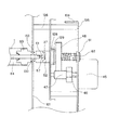
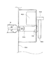
図2はプロセスカートリッジ7を画像形成装置本体に装着して、プロセスカートリッジ7内の感光体ドラム1が画像形成装置本体側板に位置決めされる様子を示した図である。図3は前記駆動ユニット103の概略構成を説明する図である。図4は駆動ユニット103と感光体ドラム1の接続形態を説明する概略構成図である。図5は駆動ユニット103と感光体ドラム1の接続形態を説明する概略構成図である。
FIG. 2 is a diagram showing a state in which the process cartridge 7 is mounted on the image forming apparatus main body, and the
プロセスカートリッジ7は、感光体ドラム1及び感光体ドラム1に作用するプロセス手段(帯電器及び現像器)を一体的にカートリッジ化したもので、ユーザー自身が画像形成装置本体に着脱可能となっている。
The process cartridge 7 is a cartridge in which the
画像形成装置本体内部には、プロセスカートリッジ7の着脱方向に沿ってガイドレール部(不図示)が設けてあり、ユーザーはこれに沿ってプロセスカートリッジ7を挿入する。この時、プロセスカートリッジ7内の感光体ドラム1を回転支持する軸受部130,1
31がそれぞれ本体右側板101及び本体左側板102のエッジ切り欠き部端面133及び134に突き当たる事によって画像形成装置本体に対して感光体ドラム1及びプロセスカートリッジ7が位置決め固定される。
Inside the image forming apparatus main body, a guide rail portion (not shown) is provided along the attaching / detaching direction of the process cartridge 7, and the user inserts the process cartridge 7 along this direction. At this time, bearing
When 31 hits the edge notch end surfaces 133 and 134 of the main body
プロセスカートリッジ7の挿入方向右側には複数の感光体ドラム1を駆動する駆動ユニット103が画像形成装置本体の右側のフレーム(本体右側板)101の外側に位置決め、固定されている。
A
図3に示すように、駆動ユニット103は駆動フレーム104上にY,M,C,Bk各色の感光体ドラム1を駆動する駆動ユニット103Y,103M,103C,103Bkがそれぞれ精度良く位置決め、固定されている。また、駆動ユニット103には駆動フレーム104に固定されたドラムモータ(駆動源)45と、モータ45のモータ軸に固定されたピニオン46と、第2駆動伝達手段(第2駆動伝達部材、第2駆動伝達ギア)としてのドラム駆動ギア48と、ピニオン46及びドラム駆動ギア48と噛み合い回転自在に支持された第1駆動伝達手段(第1駆動伝達部材、第1駆動伝達ギア)としての中間ギア47と、ドラム駆動ギア48を支持する軸受け51と、ドラム駆動ギア48先端部に形成された三角カップリング凹部52とを有する。ここで、中間ギア47は本発明に係る振動抑制部を構成している。
As shown in FIG. 3, in the
またここで、位置決めピン穴105(105a,105b)は駆動フレーム104上に2ヶ所固定されており、その位置は各色の感光体ドラム1の中心軸と同軸上(x=0)である。またBk側の位置決めピン穴(第1基準穴)105aは駆動フレーム104におけるz方向の基準でもあり(z=0)、駆動ユニット103はこの位置決めピン穴(第1基準穴)105aを基準に本体右側板101にビス止め等により固定される。
Here, the positioning pin holes 105 (105a, 105b) are fixed at two places on the
また、図4に示す様に、本体右側板101には駆動ユニット103の位置決めピン穴105と嵌合する基準ピン106が設けてある。第1基準ピン106aはx方向、z方向ともに第1基準穴105aと精度良く嵌合して駆動ユニット103の位置決めをするが、第2基準ピン106bが挿入される第2基準穴105bはz方向に延びる長丸穴形状になっており、xy方向のみ第2基準ピン106bと嵌合されて位置決めされる。
As shown in FIG. 4, the main body
次に、感光体ドラム1と駆動ユニット103との接続構成について図4,5を用いて説
明する。
Next, a connection configuration between the
ユーザーがプロセスカートリッジ7を画像形成装置本体に装着した後、転写材担持搬送ユニット(不図示)を感光体ドラム1に当接させる回転動作と連動して回転カム128が回転し、回転カム128と接続する相手側回転カム129がドラム駆動ギア48と共にリターンバネ62の付勢力によって感光体ドラム1の軸方向にスラスト移動する事によって、ドラム駆動ギア48先端部に形成された三角カップリング凹部52が感光体ドラム1端部のフランジ60に形成された三角カップリング凸部37と接続し、嵌合する事によりドラム駆動ギア48は感光体ドラム1に対して位置決め、固定されると共に、ドラム駆動ギア48の軸線が感光体ドラム1に対して同一直線上に配置される。
After the user attaches the process cartridge 7 to the main body of the image forming apparatus, the rotating
三角カップリング凹部52はねじれた正三角柱となる穴を有し、三角カップリング凸部37と軸方向に係脱される。三角カップリング凸部37と三角カップリング凹部52は嵌合時に、三角カップリング凸部37のねじれた正三角柱の稜線が三角カップリング凹部52のねじれた三角柱の面に接触することにより、三角カップリング凸部37と三角カップリング凹部52は調芯されて回転中心が一致する。
The triangular coupling
また上記において、画像形成中のドラム駆動ギア48は三角カップリング凹部52底面と三角カップリング凸部37端面が突き当たることによってプロセスカートリッジ側へ最も移動した位置でスラスト位置が定められると共に、軸受け51に沿ってリターンバネ62の付勢力に抗して後退可能に支持されている。
Further, in the above, the
また、三角カップリング凸部37と三角カップリング凹部52の三角形状の位相が合わず、三角カップリングが接続しない場合には、三角カップリング凸部37の端面が三角カップリング凹部52の口部の縁を押し、リターンバネ62の付勢力に抗してドラム駆動ギア48を画像形成装置外側へ後退させる。そして、プロセスカートリッジ7の装着後、画像形成装置本体の前回転時に三角カップリング凸部37と三角カップリング凹部52の三角形状の位相が合った時点で瞬時に接続する。
Further, when the triangular phase of the triangular coupling
以上示した様に、ドラム駆動ギア48と感光体ドラム1は、互いの三角カップリング凹部52と三角カップリング凸部37とが係合することによって初めて位置決め固定がなされると共に、駆動源であるドラムモータ45による回転駆動力が感光体ドラム1に伝達される構成となっている。
As described above, the
この構成において、ドラム駆動ギア48より上流側の中間ギア47は駆動フレーム104にカシメ支持された不図示のアイドラ軸(軸部材)と前記アイドラ軸にビス固定された駆動フレーム110(110Y,110C,110M,110Bk)によって、ピニオン46に対して精度良く回転自在に支持されており、ピニオン46に対してアライメントが悪化する事は無く、回転ムラを最小限に抑えられる構成となっている。
In this configuration, the
しかし、ドラム駆動ギア48の軸(軸部材)はギア部より画像形成装置外側は駆動フレーム104上に固定された軸受け51によって中間ギア47に対して精度良く回転自在に支持されるが、ギア部を挟んだ画像形成装置内側は感光体ドラム1端部のフランジ60に形成された三角カップリング凸部37によって位置決め、固定がなされるため、中間ギア47に対してアライメントが悪化する可能性がある。
However, the shaft (shaft member) of the
本実施の形態においては、ドラム駆動ギア48の画像形成装置内側端部の支持位置と画像形成装置外側端部の支持位置との間には、フランジ60、軸受部130、本体右側板101、位置決めピン106、駆動フレーム104、軸受け51、ドラム駆動ギア48の計
7部品が介在している構成となっている為、ドラム駆動ギア48は中間ギア47に対して0.1mm以上アライメントが悪化する可能性が大きい。これ以上アライメントが悪化すると、バックラッシュが減少して歯底当たりが発生したり歯面の片当たりが発生する可能性があり、ギア歯面が噛合う際に衝撃振動が発生して感光体ドラム上に伝達されて画像上のピッチムラレベルが悪化する可能性が高い。
In the present embodiment, the
ここで、駆動ユニット構成における本実施の形態の特徴であるギア構成について主に図6〜8を用いて説明する。図6は駆動ユニット103のギア歯面の形状を説明するための図であり、軸方向から見た1つの歯と、当該歯を側面図を示している。図7は駆動ユニット103のギアの噛み合い状態を説明するための図である。図8は駆動ユニット103のギア歯面の形状を説明するための図である。
Here, the gear configuration which is a feature of the present embodiment in the drive unit configuration will be mainly described with reference to FIGS. FIG. 6 is a view for explaining the shape of the gear tooth surface of the
駆動源であるドラムモータ45からドラム駆動ギア48へと回転力を伝達するピニオン46、中間ギア47及びドラム駆動ギア48はそれぞれモジュール0.5、ネジレ角20°の樹脂部材からなるハスバギアを用いている。特に、中間ギア47は曲げ弾性率の小さい弾性樹脂部材によって成型されており、その曲げ弾性率は、ドラム駆動ギア48の曲げ弾性率とは異なるもので、本実施の形態ではドラム駆動ギア48の曲げ弾性率の約60%以下としている。さらに、中間ギア47のギア歯面は図6(a)及び図8(a)に示すような理想の歯筋形状ではなく、図6(d)及び図8(b)に示すようなクラウニング形状を、射出成型時に意図して形成している。
The
現在、通常の射出成型の現状としては、ギア歯面の歯筋形状を図6(a)に示すような理想形状を狙って成型しても、必ずある量の歯筋形状誤差(図6中のa)が生じてしまう。例えば、歯筋形状誤差がある範囲以内に収まっているギアにおいても、図6(c)に示す様にギアの歯幅中央部が引けてしまって両端部の歯筋が凸側に狂ってしまった場合には、そのギアの噛み合い始めと噛み合いが終わる際に微小な衝撃振動が発生し、感光体ドラムに直接伝達されて画像上に顕著なピッチムラが発生してしまう。 At present, as a current state of normal injection molding, even if the tooth trace shape of the gear tooth surface is molded aiming at an ideal shape as shown in FIG. 6A, there is always a certain amount of tooth trace shape error (in FIG. 6). A) occurs. For example, even in a gear that has a tooth trace shape error within a certain range, as shown in FIG. 6 (c), the central part of the gear width of the gear is pulled and the tooth traces at both ends are skewed to the convex side. In such a case, a minute impact vibration is generated at the beginning and end of meshing of the gear, and is directly transmitted to the photosensitive drum, thereby causing remarkable pitch unevenness on the image.
つまり、図7(a)中のc−1点で両者のギアが噛み合い始めるが、この時点では図6(c)に示す歯筋形状の両端部(図7(a)の実線部)が接触しており、図7(a)中のb−1点(図6(c)の中央部が噛み合っているポイント)ではギアの歯面が瞬間的に非接触となってしまい(図7(a)の点線部)、このc−1点からb−1点への移行において、ギア歯筋形状の段差部を通過する際の衝撃振動が発生する。これはb−1点から両者の歯面が離れる図7(a)中のd−1点への移行においても同様の衝撃振動が発生する。 That is, both gears start to mesh at point c-1 in FIG. 7 (a), but at this time, both ends of the tooth trace shape shown in FIG. 6 (c) (solid line portions in FIG. 7 (a)) are in contact. At the point b-1 in FIG. 7 (a) (the point where the central portion of FIG. 6 (c) is engaged), the tooth surface of the gear is instantaneously non-contact (FIG. 7 (a)). ), And a transition from the c-1 point to the b-1 point causes an impact vibration when passing through a stepped portion having a gear tooth trace shape. The same shock vibration occurs in the transition from the point b-1 to the point d-1 in FIG.
これに対し、図7(b)は図6(d)に示す様な歯面にクラウニング形状を形成したギアの噛み合いを示したものである。図中のc−2点が両者のギアが噛み合い始めるポイントであるが、この瞬間は歯筋の端部がクラウニングによって丸められているので両者のギアはまだ接触していないが、この直後から滑らかにギアが噛み合い始めることになる。その後、b−2点を通って噛み合いが離れるd−2点の直前まで、安定してギア歯筋における中央部で噛み合う事ができるので、ギア歯筋形状の段差部を通過する際の衝撃振動が発生せず、ピッチムラが悪化するような事はない。この時、前述した様にギア歯面をクラウニング形状にすることによって噛み合い率が若干減少するが、その減少分はわずかであり、またあらかじめ噛み合い率を十分確保しておけば、それが画像上のピッチムラレベルに悪影響を及ぼす事は全くない。 On the other hand, FIG. 7 (b) shows the meshing of a gear having a crowning shape formed on the tooth surface as shown in FIG. 6 (d). The point c-2 in the figure is the point where both gears start to mesh, but at this moment the end of the tooth trace is rounded by crowning, so both gears are not yet in contact, but immediately after this, smooth The gears will begin to mesh. After that, it is possible to stably engage at the central portion of the gear tooth trace until just before the point d-2 at which the mesh is disengaged through the point b-2, so that the impact vibration when passing through the step portion of the gear tooth trace shape. Does not occur and the pitch unevenness does not deteriorate. At this time, as described above, the meshing rate is slightly reduced by making the gear tooth surface a crowning shape, but the reduction is slight, and if the meshing rate is sufficiently secured in advance, it can be seen on the image. There is no negative effect on the pitch unevenness level.
また、歯幅両端部の歯筋が狂っていない場合(図6(a))においても、カシメ軸の倒れや軸がカシメてある板金の平面度が悪くギア軸間平行度が狂ってしまった場合や、本実施例の様にドラム駆動ギア48が一方を感光体ドラム1によって位置決めされると共に、他方を本体駆動ユニットによって位置決めされる構成においてドラム駆動ギア48の位置
精度が低下し、中間ギア47とのアライメントが極端に悪化してしまう可能性のある駆動伝達構成をとった場合においても、前述したと全く同様の効果を得る事ができる。
In addition, even when the tooth traces at both ends of the tooth width are not out of order (FIG. 6A), the flatness of the sheet metal with the crimped shaft tilted or the shaft crimped is poor, and the parallelism between the gear shafts is out of order. In the case where the
これは、ギアが傾くことによってギア歯面端部が片当りして衝撃が大きくなったり、偏摩耗を来たして微小振動が増大する恐れがあるからであり、これに対しても、ギア歯面のクラウニング化は、ギアの歯幅中央部による安定した噛み合いを実現できるので、噛み合いを滑らかに保って微小振動の発生を抑制する効果を期待できる。軸間平行度の悪化はハスバギアだけでなく平歯ギアでもピッチムラ悪化要因となるので、平歯ギアを用いた画像形成駆動列においてもギア歯面のクラウニング化は有効である。 This is because when the gear is tilted, the end of the gear tooth surface comes into contact with one side and the impact becomes large, or there is a risk that micro-vibration increases due to uneven wear. Since the crowning can realize a stable meshing by the central part of the gear tooth width, an effect of suppressing the occurrence of minute vibrations by keeping the meshing smooth can be expected. The deterioration of the parallelism between the axes causes the pitch unevenness not only in the helical gear but also in the spur gear, so that the crowning of the gear tooth surface is effective even in the image forming drive train using the spur gear.
さらには、中間ギア47は曲げ弾性率の小さい弾性樹脂部材を用いて成型している為、中間ギア47とドラム駆動ギア48におけるギアの噛合い始めもしくはギアの噛合い終わりにおいて曲げ弾性率の小さいギア側の中間ギア47の歯面が撓んで噛合い時の衝撃を吸収する効果が期待できるため、よりギアの噛み合いを滑らかに保ち、微小振動の発生を防いで、実画像上のピッチムラレベルを向上させる効果を発揮する。
Furthermore, since the
以上説明した画像形成ギア列における中間ギア47の弾性樹脂化、およびギア歯面のクラウニング化の有効性は、図9のような評価によって確認できる。
The effectiveness of using the
図9は実画像に横線画像(例えば2dot横線、3dotスペース)を出力し、出力された横線のピッチ間隔のムラをFFT解析したものである。図9(a)は図6(a)に示すような理想形状を狙って成型したギアで且つドラム駆動ギア48と同じ材質にて成型した中間ギア47を用いて測定したものであり、図9(b)は中間ギア47のギア歯面をクラウニング化すると共にギア材質にドラム駆動ギア48に使用している材質の60%以下の曲げ弾性率である弾性樹脂を用いて測定した結果である。
FIG. 9 shows an image obtained by outputting a horizontal line image (for example, 2 dot horizontal line, 3 dot space) as an actual image and performing FFT analysis on the pitch interval unevenness of the output horizontal line. FIG. 9A is a measurement using an
本実施の形態の場合、中間ギア47とドラム駆動ギア48との噛み合いにて発生する噛み合い周波数はおよそ114.4Hzであるが、中間ギア47の弾性樹脂化とギア歯面のクラウニング化を行う事で、ギアの噛み合いによる微小振動が軽減されて画像上にピッチムラが発生していないことが確認できる。
In this embodiment, the meshing frequency generated by the meshing of the
以上説明した様に本実施の形態では、画像形成装置本体の両側板(本体右側板101及び本体左側板102に相当)にて位置決めされた像担持体(感光体ドラム1に相当)にカップリング(三角カップリング凹部52に相当)を介して回転駆動を伝達し、像担持体中心と同一直線上に配置された像担持体駆動ギア(ドラム駆動ギア48に相当)の、一端側を本体駆動ユニット(駆動ユニット103に相当)に設けられた軸受け部材(軸受け51に相当)と嵌合し、ギアを挟んだ他方側を像担持体に設けられたカップリング(三角カップリング凸部37に相当)に嵌合する事で前記像担持体駆動ギアのギア両側を支持する本体構成において、前記像担持体駆動ギアと駆動源(ドラムモータ45に相当)に設けられたモータピニオンギア(ピニオン46に相当)との間に少なくとも一つ以上の樹脂部材にて形成されたアイドラギア(中間ギア47に相当)を配置し、2枚の金属プレート(駆動フレーム104及び駆動フレーム110に相当)によって前記アイドラギアの回転軸をカシメ支持するギア両持ち構造を形成すると共に、前記像担持体駆動ギアと噛合う相手側の前段アイドラギアを弾性樹脂部材にて形成し、そのギア歯面を、クラウニング形状とした事を特徴とする。
As described above, in the present embodiment, coupling is performed to the image carrier (corresponding to the photosensitive drum 1) positioned by the both side plates (corresponding to the main body
この前段アイドラギアの弾性樹脂化は、その曲げ弾性率が感光体駆動ギアを形成している樹脂の曲げ弾性率の60%以下にて構成されている時に顕著にその効果を発揮し、さらに前段アイドラギア歯面のクラウニング化は、その駆動列がハスバギアにて構成されている際に特に有効である。 This pre-stage idler gear is made into an elastic resin, and the effect is remarkably exhibited when the flexural modulus is configured to be 60% or less of the flexural modulus of the resin forming the photosensitive member driving gear. The crowning of the tooth surface is particularly effective when the drive train is composed of a helical gear.
このように、前段アイドラギアを弾性樹脂化する事によって、ギアの噛合い始めもしくはギアの噛合い終わりにおいて曲げ弾性率の小さいギア側の歯面が撓んで噛合い時の衝撃を吸収する効果が得られる為、前述した様な像担持体駆動ギアの一方が本体両側板によって支持された像担持体によって位置決めされると共に、他方が本体駆動ユニットによって位置決めされるといった、像担持体駆動ギアとその上流側ギアとのアライメントが多くの部品を解する事によって悪化する可能性のある構成の画像形成装置の場合にも、その影響を最小限に抑えて画像上のピッチムラレベルを向上する事が可能となる。 Thus, by making the front idler gear into an elastic resin, the gear side tooth surface having a low bending elastic modulus is bent at the start of gear engagement or at the end of gear engagement, and the effect of absorbing the impact at the time of engagement is obtained. Therefore, one of the image carrier driving gears as described above is positioned by the image carrier supported by the both side plates of the main body, and the other is positioned by the main body driving unit and the upstream thereof. Even in the case of an image forming device with a configuration that may deteriorate due to many parts being unaligned with the side gear, it is possible to minimize the effect and improve the pitch unevenness level on the image. It becomes.
また、ギアの歯面をクラウニング形状にしておく事によって、歯幅の両端部が中央部より小さくなるので、噛み合い始めにおいては、微小時間だけ通常ギアが接触を開始するタイミングよりも遅れ、また噛み合い終わりにおいては微小時間だけ離れが早くなるので、ギアの歯幅中央部による安定した噛み合いを実現する事ができる。 Also, by setting the tooth surface of the gear to a crowning shape, both ends of the tooth width become smaller than the center part, so at the beginning of meshing, the timing of the normal gear starting to contact is delayed for a minute time, and meshing At the end, the separation becomes faster by a minute time, so that stable meshing by the central portion of the gear tooth width can be realized.
ハスバギアが噛み合う際には、そのギアの歯幅における両端部の歯筋が狂っていると、ギアの歯幅方向の一端が相手ギアと接触して噛み合い始め、他端が相手ギアから離れる事で噛み合いを終える為、衝撃振動が発生し、感光体ドラムに直接伝達されて画像上に顕著なピッチムラが発生してしまう可能性があるが、ギア歯面をクラウニング形状にしておけば微小振動の発生を抑えて画像上に発生するピッチムラレベルを低減する事が可能となる。 When the helical gear meshes, if the tooth traces at both ends of the gear width of the gear are out of order, one end of the gear in the tooth width direction comes into contact with the mating gear and the other end separates from the mating gear. Since the meshing is finished, impact vibration is generated and transmitted directly to the photosensitive drum, which may cause significant pitch unevenness on the image. However, if the gear tooth surface is crowned, minute vibration will occur. It is possible to reduce the level of pitch unevenness that occurs on the image while suppressing the above.
この時、前述した様にギア歯面をクラウニング形状にすることによって噛み合い率が若干減少するが、その減少分はわずかであり、また、あらかじめ噛み合い率を十分確保しておけば、それが画像上のピッチムラレベルに悪影響を及ぼす事は全くない。 At this time, as described above, the meshing ratio of the gear tooth surface is slightly reduced by the crowning shape. However, the decrease is slight, and if the meshing ratio is sufficiently secured in advance, it is indicated on the image. There is no negative effect on the pitch unevenness level.
このように、ギアの噛み合い始めもしくはギアの噛み合い終わりにおいて曲げ弾性率の小さいギア側の歯面が撓んで噛合い時の衝撃を吸収する効果が得られると共に、ギア歯面をクラウニング化する事によってギアの歯幅中央部による安定した噛み合いを実現し、噛み合いの際に発生する微小振動の発生を抑える事ができるので、実画像上に発生するピッチムラレベルを向上する事が可能となる。さらに、上流側ギアの回転軸を2枚の金属プレートによってカシメ支持する事によって上流側ギア列のアライメント精度を向上させると共に、駆動ユニット全体の強度の向上が実現でき、噛み合いの際に発生する微小振動の発生を最小限に抑える事が可能となる。 In this way, at the beginning of gear meshing or at the end of gear meshing, the gear side tooth surface having a low bending elastic modulus is bent to absorb the impact at the time of meshing, and the gear tooth surface is crowned. Since stable meshing by the central portion of the gear tooth width is realized and generation of minute vibrations that occur during meshing can be suppressed, it is possible to improve the level of pitch unevenness that occurs on an actual image. Furthermore, by supporting the rotating shaft of the upstream gear with caulking with two metal plates, the alignment accuracy of the upstream gear train can be improved, and the strength of the entire drive unit can be improved. It is possible to minimize the occurrence of vibration.
以上説明した作用は、前述した様な感光体駆動ギアとその上流側ギアとのアライメントが極端に悪化する可能性のある構成の画像形成装置の場合に、顕著にその効果を発揮する事ができる。また、前段アイドラギアのカシメ軸の倒れや板金の平面度悪化によって、軸間の平行度が多少狂った場合においても、同様の効果を期待できる。 The above-described operation can be remarkably exerted in the case of an image forming apparatus having a configuration in which the alignment between the photosensitive member driving gear and its upstream gear may be extremely deteriorated as described above. . The same effect can be expected even when the parallelism between the shafts is slightly out of order due to the fall of the caulking shaft of the front idler gear and the deterioration of the flatness of the sheet metal.
すなわち上述した様な駆動ユニット構成を採用する事によって、4つの像担持体と4つの露光手段の全てを画像形成装置本体の両側板にて位置決めし、各々のユニット間で発生する相互位置誤差を最小限に抑えて露光手段起因の走査方向色ズレ向上が図れると共に、ギア噛合い周波数起因のピッチムラを良化させる事が可能となり、総合的な画像の高画質化を実現することができる。 In other words, by adopting the drive unit configuration as described above, all of the four image carriers and the four exposure means are positioned by the both side plates of the image forming apparatus main body, and mutual position errors occurring between the respective units are eliminated. It is possible to improve the color misregistration in the scanning direction due to the exposure means while minimizing it, and it is possible to improve the pitch unevenness due to the gear meshing frequency, and it is possible to realize a comprehensive image quality improvement.
なお、本実施の形態においては、中間ギア47の曲げ弾性率はドラム駆動ギア48の曲げ弾性率の約60%以下としているが、ドラム駆動ギア48の曲げ弾性率が中間ギア47の曲げ弾性率の約60%以下としてもよい。また、本実施の形態では、中間ギア47のギア歯面をクラウニング形状としているが、ドラム駆動ギア48のギア歯面をクラウニング形状としてもよく、また、中間ギア47に加えて、さらにドラム駆動ギア48のギア歯面
をクラウニング形状としてもよい。
In this embodiment, the flexural modulus of the
また、中間ギア47により構成される駆動伝達手段や、ドラム駆動ギア48により構成される駆動伝達手段を、複数の駆動伝達ギア(駆動伝達部材)からなるギア列(駆動伝達部材群)で構成してもよい。この場合には、複数の駆動伝達ギアのうち少なくとも、中間ギア47またはドラム駆動ギア48に接触する駆動伝達ギア(駆動伝達部材)において、他の駆動伝達ギア(駆動伝達部材)に対して曲げ弾性率を異ならせればよい。また、複数の駆動伝達ギアのうち少なくとも、中間ギア47またはドラム駆動ギア48に接触する駆動伝達ギア(駆動伝達部材)のギア歯面をクラウニング形状とするとよい。
Further, the drive transmission means constituted by the
1 感光体ドラム
2 帯電手段
3 露光手段
4 現像手段
5 転写手段
6 クリーニング手段
7 プロセスカードリッジ
8 給送部
9 搬送手段
9a 転写搬送ベルト
10 定着部
11,12 排出ローラ対
13 排出部
37 三角カップリング凸部
45 モータ
46 モータピニオン
47 中間ギア
48 ドラム駆動ギア
51 軸受け
52 三角カップリング凹部
57 位置決め部
60 フランジ
61 嵌合穴
62 リターンバネ
64 ドラム貫通軸
101 本体右側板
102 本体左側板
103 駆動ユニット
104,110 駆動フレーム
104a 曲げ部
105 位置決めピン穴
106 位置決め基準ピン
128 回転カム
129 相手側回転カム
130,131 軸受け部
133,134 エッジ切り欠き部
DESCRIPTION OF
Claims (10)
前記第1駆動伝達手段に接触して、該第1駆動伝達手段からの駆動力を被駆動伝達部に伝達する第2駆動伝達手段と、
を備えた画像形成装置の駆動ユニットにおいて、
前記第1駆動伝達手段及び前記第2駆動伝達手段のうち少なくとも一方に、該第1駆動伝達手段が駆動力を伝達するために該第2駆動伝達手段に接触したときの振動を抑制する振動抑制部を設けたことを特徴とする画像形成装置の駆動ユニット。 First drive transmission means;
A second drive transmission means for contacting the first drive transmission means and transmitting the driving force from the first drive transmission means to the driven transmission section;
In the drive unit of the image forming apparatus provided with
Vibration suppression that suppresses vibration when the first drive transmission means contacts the second drive transmission means to transmit the driving force to at least one of the first drive transmission means and the second drive transmission means. A drive unit for an image forming apparatus, characterized in that a unit is provided.
前記振動抑制部は前記第1駆動伝達部材及び前記第2駆動伝達部材のうちいずれか一方の駆動伝達部材であって、該一方の駆動伝達部材は他方の駆動伝達部材に対して曲げ弾性率の異なる弾性部材により構成されることを特徴とする請求項1に記載の画像形成装置の駆動ユニット。 The first drive transmission means and the second drive transmission means have a first drive transmission member and a second drive transmission member, respectively, and the first drive transmission member comes into contact with the second drive transmission member to drive force. Is transmitted,
The vibration suppressing unit is one of the first drive transmission member and the second drive transmission member, and the one drive transmission member has a bending elastic modulus with respect to the other drive transmission member. The drive unit of the image forming apparatus according to claim 1, wherein the drive unit is configured by different elastic members.
前記振動抑制部は該複数の駆動伝達部材のうち少なくとも、前記第1駆動伝達手段と前記第2駆動伝達手段とのうち他方に接触する駆動伝達部材であって、当該駆動伝達部材は、他の駆動伝達部材に対して曲げ弾性率の異なる弾性部材により構成されることを特徴とする請求項1に記載の画像形成装置の駆動ユニット。 At least one of the first drive transmission unit and the second drive transmission unit includes a plurality of drive transmission members that transmit a driving force,
The vibration suppressing unit is a drive transmission member that contacts at least one of the first drive transmission unit and the second drive transmission unit among the plurality of drive transmission members. The drive unit of the image forming apparatus according to claim 1, wherein the drive unit is constituted by an elastic member having a bending elastic modulus different from that of the drive transmission member.
前記振動抑制部は前記第1駆動伝達ギア及び前記第2駆動伝達ギアのうち少なくとも一方の駆動伝達ギアであって、当該一方の駆動伝達ギアの歯面をクラウニング形状としたことを特徴とする請求項1に記載の画像形成装置の駆動ユニット。 The first drive transmission means and the second drive transmission means have a first drive transmission gear and a second drive transmission gear, respectively, and the first drive transmission gear contacts the second drive transmission gear to drive force. Is transmitted,
The vibration suppression unit is at least one of the first drive transmission gear and the second drive transmission gear, and the tooth surface of the one drive transmission gear has a crowning shape. Item 2. A drive unit for an image forming apparatus according to Item 1.
前記振動抑制部は該複数の駆動伝達ギアのうち少なくとも、前記第1駆動伝達手段と前記第2駆動伝達手段とのうち他方に接触する駆動伝達ギアであって、当該駆動伝達ギアの歯面をクラウニング形状としたことを特徴とする請求項1に記載の画像形成装置の駆動ユニット。 At least one of the first drive transmission means and the second drive transmission means has a plurality of drive transmission gears for transmitting a driving force,
The vibration suppression unit is a drive transmission gear that contacts at least one of the first drive transmission unit and the second drive transmission unit among the plurality of drive transmission gears, and has a tooth surface of the drive transmission gear. The drive unit of the image forming apparatus according to claim 1, wherein the driving unit has a crowning shape.
前記第2駆動伝達手段は、一端がユニット本体に支持され他端が被駆動伝達部である像担持体の回転軸に接続される軸部材を有することを特徴とする請求項1〜8のいずれか1項に記載の画像形成装置の駆動ユニット。 The first drive transmission means has a shaft member supported at both ends by the unit body,
9. The second drive transmission means includes a shaft member having one end supported by the unit body and the other end connected to a rotation shaft of an image carrier having a driven transmission portion. A drive unit of the image forming apparatus according to claim 1.
前記駆動ユニットに接続することにより駆動力が伝達される像担持体と、
を備えることを特徴とする画像形成装置。 A drive unit of the image forming apparatus according to any one of claims 1 to 9,
An image carrier to which driving force is transmitted by being connected to the driving unit;
An image forming apparatus comprising:
Priority Applications (1)
| Application Number | Priority Date | Filing Date | Title |
|---|---|---|---|
| JP2004110055A JP2005292634A (en) | 2004-04-02 | 2004-04-02 | Image forming apparatus drive unit and image forming apparatus |
Applications Claiming Priority (1)
| Application Number | Priority Date | Filing Date | Title |
|---|---|---|---|
| JP2004110055A JP2005292634A (en) | 2004-04-02 | 2004-04-02 | Image forming apparatus drive unit and image forming apparatus |
Publications (1)
| Publication Number | Publication Date |
|---|---|
| JP2005292634A true JP2005292634A (en) | 2005-10-20 |
Family
ID=35325596
Family Applications (1)
| Application Number | Title | Priority Date | Filing Date |
|---|---|---|---|
| JP2004110055A Withdrawn JP2005292634A (en) | 2004-04-02 | 2004-04-02 | Image forming apparatus drive unit and image forming apparatus |
Country Status (1)
| Country | Link |
|---|---|
| JP (1) | JP2005292634A (en) |
Cited By (6)
| Publication number | Priority date | Publication date | Assignee | Title |
|---|---|---|---|---|
| JP2008202648A (en) * | 2007-02-19 | 2008-09-04 | Japan Servo Co Ltd | Gear unit and actuator for printer having the same |
| US7926380B2 (en) | 2006-05-17 | 2011-04-19 | Murata Machinery, Ltd. | Resin gears, developing unit, photoconductor drum unit, image forming apparatus or image reading apparatus having the same |
| KR101139245B1 (en) | 2010-07-12 | 2012-05-14 | 삼성전자주식회사 | Driving device usable with image forming apparatus and image forming apparatus having the same |
| JP2014089483A (en) * | 2014-02-20 | 2014-05-15 | Canon Inc | Image forming apparatus |
| JP2015084020A (en) * | 2013-10-25 | 2015-04-30 | 株式会社リコー | Drive transmission device and image forming apparatus |
| JP2022011339A (en) * | 2020-06-30 | 2022-01-17 | コニカミノルタ株式会社 | Image forming device |
-
2004
- 2004-04-02 JP JP2004110055A patent/JP2005292634A/en not_active Withdrawn
Cited By (8)
| Publication number | Priority date | Publication date | Assignee | Title |
|---|---|---|---|---|
| US7926380B2 (en) | 2006-05-17 | 2011-04-19 | Murata Machinery, Ltd. | Resin gears, developing unit, photoconductor drum unit, image forming apparatus or image reading apparatus having the same |
| JP2008202648A (en) * | 2007-02-19 | 2008-09-04 | Japan Servo Co Ltd | Gear unit and actuator for printer having the same |
| KR101139245B1 (en) | 2010-07-12 | 2012-05-14 | 삼성전자주식회사 | Driving device usable with image forming apparatus and image forming apparatus having the same |
| US8583012B2 (en) | 2010-07-12 | 2013-11-12 | Samsung Electronics Co., Ltd. | Driving device usable with image forming apparatus and image forming apparatus having the same |
| JP2015084020A (en) * | 2013-10-25 | 2015-04-30 | 株式会社リコー | Drive transmission device and image forming apparatus |
| JP2014089483A (en) * | 2014-02-20 | 2014-05-15 | Canon Inc | Image forming apparatus |
| JP2022011339A (en) * | 2020-06-30 | 2022-01-17 | コニカミノルタ株式会社 | Image forming device |
| JP7508897B2 (en) | 2020-06-30 | 2024-07-02 | コニカミノルタ株式会社 | Image forming device |
Similar Documents
| Publication | Publication Date | Title |
|---|---|---|
| US7212773B2 (en) | Image forming apparatus | |
| JP2001147618A (en) | Image forming device | |
| JP5049486B2 (en) | Image forming apparatus and image carrier unit applied thereto | |
| CN103792810B (en) | Image processing system | |
| JP2014044276A (en) | Drive transmission apparatus and image forming device | |
| JP5402557B2 (en) | Image forming apparatus | |
| US20100329729A1 (en) | Image forming apparatus | |
| JP2005292634A (en) | Image forming apparatus drive unit and image forming apparatus | |
| JP5773257B2 (en) | Drive transmission device and image forming apparatus | |
| US11209743B2 (en) | Image forming apparatus | |
| JP5354371B2 (en) | Image forming apparatus | |
| JP4780163B2 (en) | Imaging unit and image forming apparatus | |
| JP2004013030A (en) | Image forming apparatus | |
| JP4658709B2 (en) | Process cartridge and image forming apparatus | |
| CN116610015B (en) | Transfer unit and image forming apparatus including the same | |
| JP2004258353A (en) | Image forming device | |
| JP4378127B2 (en) | Axis center positioning method of drive transmission member | |
| JP5212534B2 (en) | Image forming apparatus | |
| JP2010053948A (en) | Pendulum gear mechanism and image forming device | |
| JP6508578B2 (en) | Drive transmission device and image forming apparatus | |
| JP6555570B2 (en) | Driving device and image forming apparatus | |
| JP6003688B2 (en) | Transfer device and image forming apparatus | |
| KR102415348B1 (en) | Drive transmission device and image forming apparatus | |
| JP2008262096A (en) | Image forming apparatus | |
| JP2005338391A (en) | Image carrier unit, process cartridge, and color image forming apparatus |
Legal Events
| Date | Code | Title | Description |
|---|---|---|---|
| A300 | Withdrawal of application because of no request for examination |
Free format text: JAPANESE INTERMEDIATE CODE: A300 Effective date: 20070605 |