JP2005292630A - Developer supply container and image forming apparatus - Google Patents

Developer supply container and image forming apparatus Download PDF

Info

Publication number
JP2005292630A
JP2005292630A JP2004110032A JP2004110032A JP2005292630A JP 2005292630 A JP2005292630 A JP 2005292630A JP 2004110032 A JP2004110032 A JP 2004110032A JP 2004110032 A JP2004110032 A JP 2004110032A JP 2005292630 A JP2005292630 A JP 2005292630A
Authority
JP
Japan
Prior art keywords
developer
container
cap member
main body
discharge opening
Prior art date
Legal status (The legal status is an assumption and is not a legal conclusion. Google has not performed a legal analysis and makes no representation as to the accuracy of the status listed.)
Withdrawn
Application number
JP2004110032A
Other languages
Japanese (ja)
Inventor
Toshiaki Nagashima
長嶋  利明
Takeya Murakami
村上  雄也
Current Assignee (The listed assignees may be inaccurate. Google has not performed a legal analysis and makes no representation or warranty as to the accuracy of the list.)
Canon Inc
Original Assignee
Canon Inc
Priority date (The priority date is an assumption and is not a legal conclusion. Google has not performed a legal analysis and makes no representation as to the accuracy of the date listed.)
Filing date
Publication date
Application filed by Canon Inc filed Critical Canon Inc
Priority to JP2004110032A priority Critical patent/JP2005292630A/en
Publication of JP2005292630A publication Critical patent/JP2005292630A/en
Withdrawn legal-status Critical Current

Links

Images

Landscapes

  • Dry Development In Electrophotography (AREA)

Abstract

【課題】構造、組立が簡単で、安定した現像剤の補給が可能な現像剤補給容器を提供すること。
【解決手段】現像剤を収納する容器本体の一端面に、容器本体の直径よりも小さい直径の円筒状の開口部と、該開口部を封止するキャップ部材を有した現像剤補給容器であって、前記キャップ部材には前記容器本体の円筒状の開口部の内周面に沿うように円弧状に複数のシート部材を設け、開封時には前記容器本体と前記キャップ部材とが相対的に離間し、前記開口部内の現像剤を崩すことを特徴とするトナー補給容器である。
【選択図】図1
Disclosed is a developer supply container that is simple in structure and assembly and that can stably supply developer.
A developer supply container having a cylindrical opening having a diameter smaller than the diameter of a container main body and a cap member for sealing the opening on one end surface of the container main body that stores the developer. The cap member is provided with a plurality of sheet members in an arc shape along the inner peripheral surface of the cylindrical opening of the container body, and the container body and the cap member are relatively spaced apart when opened. The toner replenishing container is characterized by breaking the developer in the opening.
[Selection] Figure 1

Description

本発明は、静電式複写機、プリンタ等の画像形成装置の現像装置に現像剤を供給するために用いられる現像剤補給容器及びこれを装着して画像を形成する画像形成装置に関するものである。尚、ここで言う現像剤とは、1、2成分トナー、キャリア及びその混合物全てを含むものを指す。   The present invention relates to a developer supply container used for supplying a developer to a developing device of an image forming apparatus such as an electrostatic copying machine or a printer, and an image forming apparatus for mounting the developer supplying container to form an image. . The developer referred to here refers to a developer containing all of a one-component toner, a carrier and a mixture thereof.

従来、静電式複写機、プリンタ等の画像形成装置には粉末トナーが使用されているが、このトナーの補給容器は一般に合成樹脂等で作られた円筒状もしくは直方体等の本体と、本体から粉末トナーを現像装置に補給するために開口している本体の開口部を封止するシール部材によって構成されている。特に、このトナー補給容器に感光ドラム、クリーナー、帯電器等を一体化させたプロセスカートリッジも作られている。   Conventionally, powder toner is used in image forming apparatuses such as electrostatic copying machines and printers. This toner supply container is generally made of a cylindrical or rectangular parallelepiped body made of synthetic resin, etc. It is constituted by a seal member that seals the opening of the main body that is opened to supply powder toner to the developing device. In particular, a process cartridge in which a photosensitive drum, a cleaner, a charger, and the like are integrated with the toner supply container is also made.

最近では、操作性向上、複写機やプリンタ本体小型化のための省スペース化を目的として、本体内に据え置く現像剤補給容器が増えている。   Recently, for the purpose of improving the operability and reducing the space for copying machines and printers, the number of developer supply containers installed in the main body is increasing.

中でも、螺旋状のリブを設けた容器本体を回転させて容器本体内の現像剤を搬送し、容器本体の一端に設けた排出口から現像剤を排出させる構成の現像剤補給容器が多数提案されており、特に、現像剤排出口部の現像剤のブリッジによる閉塞を防止する提案がなされている(例えば、特許文献1〜3参照)。   In particular, a number of developer supply containers have been proposed that are configured to rotate the container body provided with spiral ribs to transport the developer in the container body, and to discharge the developer from a discharge port provided at one end of the container body. In particular, proposals have been made to prevent the developer discharge port portion from being blocked by the bridge of the developer (see, for example, Patent Documents 1 to 3).

又、最近では、容器本体内部に搬送部材を配置して、容器本体を回転させて容器本体内の現像剤を搬送させ、容器本体の一端に設けた排出口から現像剤を排出させる構成の容器であって、排出口を封止しているキャップ部材が画像形成装置本体から駆動を受けて容器本体を回転させる構成の現像剤補給容器の提案もなされている(例えば、特許文献4参照)。   Also, recently, a container having a configuration in which a conveying member is disposed inside the container body, the container body is rotated to convey the developer in the container body, and the developer is discharged from a discharge port provided at one end of the container body. There has also been proposed a developer supply container having a configuration in which the cap member sealing the discharge port is driven by the image forming apparatus main body to rotate the container main body (see, for example, Patent Document 4).

特開平8−211719号公報Japanese Patent Laid-Open No. 8-21719 特開平9−96959号公報Japanese Patent Application Laid-Open No. 9-96959 特開平10−142918号公報JP-A-10-142918 特開2002−318490号公報JP 2002-318490 A

しかしながら、従来方式では、現像剤排出量の安定化、現像剤排出開口部のシール性向上の観点から、容器本体内部の現像剤を容器本体よりも小径の排出開口部に搬送して排出させる構成になっており、用いる現像剤の物性や現像剤補給容器の物流、放置状態によっては排出開口部にてブリッジを起こして閉塞する場合があった。   However, in the conventional method, from the viewpoint of stabilizing the developer discharge amount and improving the sealability of the developer discharge opening, the developer inside the container body is transported to the discharge opening having a smaller diameter than the container body and discharged. Depending on the physical properties of the developer used, the distribution of the developer replenishing container, and the standing state, there was a case where a bridge was caused at the discharge opening portion to be blocked.

特に、前記特許文献1〜3の現像剤補給容器の構成では、現像剤排出開口部を封止している栓部材に解し部材を設けて、現像剤補給時には容器本体を回転させて現像剤を搬送させるが、容器本体と栓部材を相対的に回転させることで、容器本体の排出開口部に溜まった現像剤を栓部材の解し部材で崩して現像剤を排出させる構成になっている。この場合、容器本体の排出開口部に対し栓部材の解し部材は回転差を有して排出開口部の現像剤を解すが、より効率をアップさせたり、凝集性の高い現像剤を用いた場合には、大幅なトルクアップが生じる可能性があった。
In particular, in the configuration of the developer supply container of Patent Documents 1 to 3, a developer member is provided on the plug member that seals the developer discharge opening, and the container body is rotated when the developer is supplied. However, by rotating the container main body and the plug member relatively, the developer accumulated in the discharge opening of the container main body is broken by the opening member of the plug member, and the developer is discharged. . In this case, the unplugging member of the plug member has a rotational difference with respect to the discharge opening of the container body, and the developer of the discharge opening is released. However, the developer is more efficient or a highly cohesive developer is used. In some cases, a significant torque increase may occur.

又、解し性能を向上させるためには解し部材の剛性を上げる必要があり、より強度アップするために使用する材質が限定され、コストアップする場合があった。更に、容器本体に摺擦させる場合には、粗大粒子発生の可能性があった。   Further, in order to improve the unraveling performance, it is necessary to increase the rigidity of the unraveling member, and the material used for increasing the strength is limited, which may increase the cost. Further, when the container main body is rubbed, there is a possibility of generation of coarse particles.

前記特許文献4の現像剤補給容器の構成では、排出口を封止しているキャップ部材が画像形成装置本体から駆動を受けて容器本体と一緒に回転して容器本体内の現像剤を排出させる構成であるため、トルクアップや粗大粒子発生の可能性は無いが、用いる現像剤の物性や現像剤補給容器の物流、放置状態によっては排出開口部にてブリッジを起こして現像剤の排出が低下する可能性があった。   In the configuration of the developer supply container of Patent Document 4, the cap member sealing the discharge port is driven by the image forming apparatus body and rotates together with the container body to discharge the developer in the container body. Because of this configuration, there is no possibility of torque increase or generation of coarse particles, but depending on the physical properties of the developer used, the distribution of the developer supply container, and the standing condition, a bridge may be caused at the discharge opening to reduce developer discharge. There was a possibility.

本発明は、構造、組立が簡単で、安定した現像剤の補給が可能な現像剤補給容器を提案するものである。   The present invention proposes a developer supply container that is simple in structure and assembly and that can supply developer stably.

上記目的を達成するため、本発明は、現像剤を収納する容器本体の一端面に、容器本体の直径よりも小さい直径の円筒状の開口部と、該開口部を封止するキャップ部材を有した現像剤補給容器であって、前記キャップ部材には前記容器本体の円筒状の開口部の内周面に沿うように円弧状に複数のシート部材を設け、開封時には前記容器本体と前記キャップ部材とが相対的に離間し、前記開口部内の現像剤を崩すことを特徴とするトナー補給容器である。   In order to achieve the above object, the present invention has a cylindrical opening having a diameter smaller than the diameter of the container main body and a cap member for sealing the opening at one end surface of the container main body that stores the developer. In the developer supply container, the cap member is provided with a plurality of sheet members in an arc shape along the inner peripheral surface of the cylindrical opening of the container body, and the container body and the cap member are opened when opened. And a toner replenishing container characterized in that the developer in the opening is destroyed.

本発明によれば、簡単な構成でコストアップを招くことなく、現像剤排出口部にて閉塞することなく、安定した現像剤の補給を確実に行うことができる。   According to the present invention, it is possible to reliably supply a stable developer without causing an increase in cost with a simple configuration and without blocking at the developer discharge port.

又、現像剤の定量供給やフラッシング対策を図ることができる。   Further, it is possible to take a fixed amount of developer and take measures against flushing.

以下に本発明の実施の形態を添付図面に基づいて説明する。   Embodiments of the present invention will be described below with reference to the accompanying drawings.

<実施の形態1>
[電子写真画像形成装置]
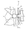
先ず、本発明に係る現像剤補給容器が装着される画像形成装置の一例である電子写真画像形成装置の構成について図1に基づいて説明する。
<Embodiment 1>
[Electrophotographic image forming apparatus]
First, the configuration of an electrophotographic image forming apparatus which is an example of an image forming apparatus to which a developer supply container according to the present invention is mounted will be described with reference to FIG.

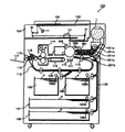
図1に示す電子写真複写機本体(以下、「装置本体」と言う)装置本体100において、原稿101が原稿台ガラス102の上に置かれると、原稿101の画像情報に応じた光像が光学部103の複数のミラーMとレンズLnにより、像担持体としての電子写真感光体ドラム(以下、「感光体ドラム」と言う)104上に結像する。カセット105,106,107,108に積載された記録媒体(以下、「媒体」と言う)Pのうち、図2に示す操作部100a(図2参照)から使用者(ユーザー)が入力した情報若しくは原稿101の媒体サイズから、最適な媒体Pをカセット105〜108の媒体サイズ情報から選択する。ここで、記録媒体としては上記媒体に限定されずに、例えばOHPシート等適宜選択できる。   In an electrophotographic copying machine main body (hereinafter referred to as “apparatus main body”) 100 shown in FIG. 1, when an original 101 is placed on an original platen glass 102, an optical image corresponding to image information of the original 101 is optical. An image is formed on an electrophotographic photosensitive drum (hereinafter referred to as “photosensitive drum”) 104 as an image carrier by a plurality of mirrors M and lenses Ln of the unit 103. Of the recording media (hereinafter referred to as “medium”) P loaded in the cassettes 105, 106, 107, 108, information input by the user (user) from the operation unit 100a (see FIG. 2) shown in FIG. From the medium size of the original 101, the optimum medium P is selected from the medium size information of the cassettes 105-108. Here, the recording medium is not limited to the above medium, and may be selected as appropriate, for example, an OHP sheet.

そして、給送・分離装置105A,106A,107A,108Aにより搬送された1枚の媒体Pを、搬送部109を経由してレジストローラ110まで搬送し、更にレジストローラ110により媒体Pを感光体ドラム104の回転と、光学部103のスキャンのタイミングを同期させて転写部に搬送する。転写部では、転写放電器111によって、感光体ドラム104上に形成された現像剤像(トナー像)を媒体Pに転写する。そして、分離放電器112によって、トナー像の転写された媒体Pを感光体ドラム104から分離する。   Then, one medium P conveyed by the feeding / separating devices 105A, 106A, 107A, and 108A is conveyed to the registration roller 110 via the conveyance unit 109, and the medium P is further transferred by the registration roller 110 to the photosensitive drum. The rotation of 104 and the scanning timing of the optical unit 103 are synchronized and conveyed to the transfer unit. In the transfer unit, the developer image (toner image) formed on the photosensitive drum 104 is transferred to the medium P by the transfer discharger 111. Then, the separation discharger 112 separates the medium P on which the toner image is transferred from the photosensitive drum 104.

その後、搬送部113により定着部114へ搬送された媒体Pは、定着部114において熱と圧力により媒体P上のトナー像を定着させた後、片面コピーの場合には、排出反転部115を通過し、排出ローラ116により排出トレイ117へ排出される。又、両面コピーの場合には、排出反転部115のフラッパ118の制御により、再給送搬送路119,120を経由してレジストローラ110まで搬送された後、片面コピーの場合と同様の経路を辿って排出トレイ117へ排出される。   Thereafter, the medium P transported to the fixing unit 114 by the transport unit 113 fixes the toner image on the medium P by heat and pressure in the fixing unit 114 and then passes through the discharge reversing unit 115 in the case of single-sided copying. Then, the paper is discharged to the discharge tray 117 by the discharge roller 116. In the case of double-sided copying, the paper is conveyed to the registration roller 110 via the refeed conveyance paths 119 and 120 under the control of the flapper 118 of the discharge reversing unit 115, and then the same path as in the case of single-sided copying. Traces and is discharged to the discharge tray 117.

又、多重コピーの場合には、媒体Pは排出反転部115を通り、一度排出ローラ116により一部が装置外へ排出される。そして、この後、媒体Pの終端がフラッパ118を通過し、排出ローラ116に未だ挟持されているタイミングでフラッパ118を制御すると共に排出ローラ116を逆回転させることにより、再度装置本体100内へ搬送される。更にこの後、再給送搬送路115,120を経由してレジストローラ110まで搬送された後、片面コピーの場合と同様の経路を辿って排出トレイ117へ排出される。   In the case of multiple copying, the medium P passes through the discharge reversing unit 115 and is once discharged out of the apparatus by the discharge roller 116. After that, the end of the medium P passes through the flapper 118, and the flapper 118 is controlled at the timing when it is still nipped by the discharge roller 116, and the discharge roller 116 is reversely rotated, so that it is conveyed again into the apparatus main body 100. Is done. Thereafter, the sheet is conveyed to the registration roller 110 via the refeed conveyance paths 115 and 120, and then discharged to the discharge tray 117 along the same path as in the case of single-sided copying.

ところで、上記構成の装置本体100において、感光体ドラム104の周りには現像手段としての現像装置201、クリーナ装置202、一次帯電器203等が配置されている。現像装置201は、原稿101の画像情報に基づいて一様に帯電された感光体ドラム104上を光学部103により露光して形成された静電潜像を、現像剤(トナー)を用いて現像するものである。そして、この現像装置201へ現像剤としてのトナーを補給するための現像剤補給容器1が使用者によって装置本体100に着脱可能に装着されている。尚、現像剤補給容器からトナーのみを画像形成装置側へ補給する場合や、トナー及びキャリアを補給する場合であっても本発明を適用できる。本実施形態では前者の例についての説明である。   In the apparatus main body 100 having the above-described configuration, a developing device 201 as a developing unit, a cleaner device 202, a primary charger 203, and the like are disposed around the photosensitive drum 104. The developing device 201 develops, using a developer (toner), an electrostatic latent image formed by exposing the photosensitive drum 104 uniformly charged based on the image information of the document 101 by the optical unit 103. To do. A developer supply container 1 for supplying toner as a developer to the developing device 201 is detachably attached to the apparatus main body 100 by a user. Note that the present invention can be applied even when only toner is supplied from the developer supply container to the image forming apparatus side, or when toner and carrier are supplied. In the present embodiment, the former example will be described.

又、現像装置201は、収容手段としてのトナーホッパー201aと現像器201bとを有している。トナーホッパー201aは、現像剤補給容器1から補給されたトナーを撹拌するための撹拌部材201cを有している。そして、この撹拌部材201cにより撹拌されたトナーは、マグネットローラ201dにより現像器201bに送られる。現像器201bは、現像ローラ201fと、送り部材201eを有している。そして、マグネットローラ201dによりトナーホッパー201aから送られたトナーは、送り部材201eにより現像ローラ201fに送られて、この現像ローラ201fにより感光体ドラム104に供給される。尚、クリーナ装置202は、感光体ドラム104に残留しているトナーを除去するためのものである。又、一次帯電器203は、感光体ドラム104を帯電するためのものである。   Further, the developing device 201 includes a toner hopper 201a and a developing device 201b as storage means. The toner hopper 201a has an agitating member 201c for agitating the toner replenished from the developer replenishing container 1. The toner stirred by the stirring member 201c is sent to the developing device 201b by the magnet roller 201d. The developing device 201b includes a developing roller 201f and a feeding member 201e. The toner sent from the toner hopper 201a by the magnet roller 201d is sent to the developing roller 201f by the feeding member 201e, and is supplied to the photosensitive drum 104 by the developing roller 201f. The cleaner device 202 is for removing the toner remaining on the photosensitive drum 104. The primary charger 203 is for charging the photosensitive drum 104.

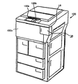
図2に示す外装カバーの一部である現像剤補給容器交換用前カバー20(以下、「容器交換用前カバー」と言う)を図3に示すように使用者が開けると、装着手段の一部である容器受け台50が、駆動系(不図示)によって所定の位置まで引き出される。そして、この容器受け台50上に現像剤補給容器1を載置する。使用者が現像剤補給容器1を装置本体100から取り出す際には、容器受け台50を引き出し、容器受け台50に載っている現像剤補給容器1を取り出す。ここで、容器交換用前カバー20は現像剤補給容器1を着脱(交換)するための専用カバーであって、現像剤補給容器1を着脱するためだけに開閉される。尚、装置本体100のメンテナンスは、前面カバー100cを開閉することによって行われる。又、容器受け台50を介することなく、現像剤補給容器1を装置本体100に直接装着し、又、装置本体100から取り外しても良い。   When the user opens the developer supply container replacement front cover 20 (hereinafter referred to as “the container replacement front cover”), which is a part of the exterior cover shown in FIG. 2, as shown in FIG. The container cradle 50 which is a part is pulled out to a predetermined position by a drive system (not shown). Then, the developer supply container 1 is placed on the container cradle 50. When the user takes out the developer supply container 1 from the apparatus main body 100, the container receiving base 50 is pulled out, and the developer supply container 1 placed on the container receiving base 50 is taken out. Here, the container replacement front cover 20 is a dedicated cover for attaching / detaching (replacing) the developer supply container 1 and is opened and closed only for attaching / detaching the developer supply container 1. The maintenance of the apparatus main body 100 is performed by opening and closing the front cover 100c. Further, the developer supply container 1 may be directly attached to the apparatus main body 100 without being connected to the container cradle 50 and may be detached from the apparatus main body 100.

[現像剤補給容器について]
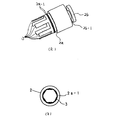
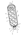
実施の形態1の現像剤補給容器1の構成を示す断面図を図4に示す。実施の形態1の現像剤補給容器は、主に容器本体1A、キャップ部材2、シート部材3、現像剤4から構成されている。
[About developer supply container]
FIG. 4 is a cross-sectional view showing the configuration of the developer supply container 1 of the first embodiment. The developer supply container of Embodiment 1 is mainly composed of a container body 1A, a cap member 2, a sheet member 3, and a developer 4.

次に、各部材について説明する。   Next, each member will be described.

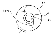
容器本体1Aは本実施例では略円筒形状でブロー成型にて成型しており、主には胴部1bと胴部1bの直径よりも小さい略円筒形状の現像剤排出開口1aを有している。胴部1bには容器本体1A内部の現像剤4を現像剤排出開口1aに送るための螺旋形状部1b−1を形成しており、現像剤排出時には補給ユニット30側から駆動を受けて容器本体1Aが回転し、その螺旋形状部1b−1に現像剤4を載せて現像剤排出開口1aの方向に現像剤4を搬送する。   In the present embodiment, the container main body 1A has a substantially cylindrical shape and is formed by blow molding, and mainly includes a barrel portion 1b and a substantially cylindrical developer discharge opening 1a smaller than the diameter of the barrel portion 1b. . The body portion 1b is formed with a spiral-shaped portion 1b-1 for sending the developer 4 inside the container body 1A to the developer discharge opening 1a. When the developer is discharged, the container body is driven by the supply unit 30 side. 1A rotates, the developer 4 is placed on the spiral-shaped portion 1b-1, and the developer 4 is conveyed in the direction of the developer discharge opening 1a.

尚、螺旋形状部1b−1の螺旋のピッチ、高さ、角度等の形状は、要求される排出性能に合せて適宜選定することが望ましい。螺旋形状部1b−1は断面が容器本体1A内部に向かって立つ二等辺の三角形としている。これにより、容器本体1Aから現像剤排出後に最終的に容器本体1Aに残る残量が螺旋形状部1b−1の隅に残り難くしている。又、容器本体1Aの外周面上に螺旋形状部1b−1に沿って溝1b−2が設けてあり、螺旋形状部1b−1の部分における肉厚を胴部1bの外周円筒の肉厚とほぼ等しくすることにより樹脂成型を容易にしている。   In addition, it is desirable that the shape of the spiral shape portion 1b-1 such as the pitch, height, and angle of the spiral is appropriately selected according to the required discharge performance. The spiral-shaped portion 1b-1 is an isosceles triangle whose cross section stands toward the inside of the container body 1A. This makes it difficult for the remaining amount remaining in the container body 1A after the developer is discharged from the container body 1A to remain in the corners of the spiral portion 1b-1. Further, a groove 1b-2 is provided on the outer peripheral surface of the container main body 1A along the spiral-shaped portion 1b-1, and the thickness of the portion of the spiral-shaped portion 1b-1 is set to the thickness of the outer peripheral cylinder of the trunk portion 1b. Resin molding is facilitated by making them substantially equal.

胴部1bの現像剤排出開口1aとの接点部には、図5に示す通り容器本体1A内部から搬送されてきた現像剤4を現像剤排出開口1aに確実に供給するためのすくい上げ部1b−3を有しており、このすくい上げ部1b−3は、容器本体1Aの内周と、現像剤排出開口1aを容器本体1A内へ仮想的に延長した仮想円筒とを曲面で結合したものであり、そのすくい上げ面は容器本体1Aの回転中心側から外周へいく程、図示矢印イの現像剤補給容器1の回転方向に関し次第に位相が進んでいる。このすくい上げ部1b−3は、容器本体1Aの回転中心線の方向で見て現像剤排出開口1a付近にのみ存在する。よって、すくい上げ部1b−3は現像剤補給容器1の回転中心部分には存在しない。   As shown in FIG. 5, a scooping portion 1b− for reliably supplying the developer 4 conveyed from the inside of the container main body 1A to the developer discharge opening 1a is provided at the contact portion of the body portion 1b with the developer discharge opening 1a. The scooping portion 1b-3 is formed by connecting the inner periphery of the container body 1A and a virtual cylinder obtained by virtually extending the developer discharge opening 1a into the container body 1A with a curved surface. The phase of the scooping surface gradually advances with respect to the rotation direction of the developer supply container 1 indicated by the arrow A as it goes from the rotation center side of the container body 1A to the outer periphery. The scooping portion 1b-3 exists only in the vicinity of the developer discharge opening 1a when viewed in the direction of the rotation center line of the container body 1A. Therefore, the scooping portion 1 b-3 does not exist at the rotation center portion of the developer supply container 1.

容器本体1Aの各寸法は実際の現像剤充填量、排出性能によって適宜選択するのが望ましいが、容器回転時にねじれ等の変形が無い程度の剛性が必要である。   Each dimension of the container main body 1A is preferably selected as appropriate according to the actual developer filling amount and discharge performance, but the rigidity is required so that there is no deformation such as twisting when the container rotates.

更に、本実施の形態では、ブロー成型にて一体成型したが、胴部1bと現像剤排出開口1a周辺部とを別体として射出成型にて成型した後接合させる構成でも構わず、成型方法に合せて材質もポリプロピレン、ポリエチレン、ポリスチレン、ABS等自由に選択することができる。本例では、ポリプロピレンを用いた。   Furthermore, in the present embodiment, it is integrally formed by blow molding. However, the body 1b and the peripheral portion of the developer discharge opening 1a may be separately formed by injection molding and then joined. In addition, the material can be freely selected from polypropylene, polyethylene, polystyrene, ABS and the like. In this example, polypropylene was used.

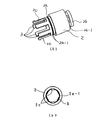
キャップ部材2は容器本体1Aの現像剤排出開口1aを封止するものであり、現像剤排出開口1aとの封止部2aを更に開封時に補給ユニット30に係合する係合部2bを有している。又、図6に示す通り、略円筒状の現像剤排出開口1aの内周面に合せてシート部材3を設けた。   The cap member 2 seals the developer discharge opening 1a of the container main body 1A, and has an engagement portion 2b that engages the replenishment unit 30 when the sealing portion 2a with the developer discharge opening 1a is further opened. ing. Further, as shown in FIG. 6, the sheet member 3 is provided in accordance with the inner peripheral surface of the substantially cylindrical developer discharge opening 1a.

封止部2aには、円筒形の外周を取り巻くリブ2a−1が設けてあり、現像剤排出開口1aの内周に密接して、容器本体1A内の現像剤4が外部へ漏れないように封止する必要があるが、同時にキャップ部材2の開閉操作が滑らかであることも併せ持つ必要がある。   The sealing portion 2a is provided with a rib 2a-1 surrounding the outer periphery of the cylindrical shape so as to be in close contact with the inner periphery of the developer discharge opening 1a so that the developer 4 in the container main body 1A does not leak to the outside. It is necessary to seal, but at the same time, it is necessary to have a smooth opening / closing operation of the cap member 2.

係合部2bは、補給ユニット30に装着して開封する時に補給ユニット30と係合して、更に現像剤排出時には容器本体1Aと一緒に回転する駆動を補給ユニット30から受ける必要がある。   The engaging portion 2b needs to be engaged with the replenishment unit 30 when the replenishment unit 30 is attached and opened, and further receives a drive from the replenishment unit 30 that rotates together with the container body 1A when the developer is discharged.

シート部材3は、キャップ部材2の封止部2aの円筒形の外周部から容器本体1A内部方向へ現像剤排出開口1aの内周面に沿って円弧状の片を円周方向に6箇所設けた。本実施の形態では、キャップ部材2の成型時にキャップ部材2の一部として一体成型を行った。このシート部材3は、キャップ部材2閉時には容器本体1Aの現像剤排出開口1aの円筒内周面に近接した位置に配置され、円筒内部に現像剤4が圧密された場合には円筒部と現像剤4の間に配置された状態になることから、キャップ部材2開封時にはキャップ部材2が容器本体1Aから離間されるに連れて現像剤排出開口1aの円筒部内の現像剤4を載せて引きずり出すと同時に崩すことが可能になる。このシート部材3の厚みは現像剤排出開口1a内部の閉塞を防ぐためにより大きな空間を得るよう薄い方が望ましく、又、シート部材3の幅はシート部材3の内部の現像剤4が崩れ易くするためにシート部材3が無い部分に対し同等程度にすることが望ましい。   The sheet member 3 is provided with six arc-shaped pieces in the circumferential direction along the inner peripheral surface of the developer discharge opening 1a from the cylindrical outer peripheral portion of the sealing portion 2a of the cap member 2 toward the inside of the container main body 1A. It was. In the present embodiment, integral molding is performed as a part of the cap member 2 when the cap member 2 is molded. When the cap member 2 is closed, the sheet member 3 is disposed at a position close to the cylindrical inner peripheral surface of the developer discharge opening 1a of the container main body 1A. When the developer 4 is consolidated inside the cylinder, the sheet member 3 is developed with the cylindrical portion. Since the cap member 2 is opened when the cap member 2 is opened, the developer 4 in the cylindrical portion of the developer discharge opening 1a is placed and dragged as the cap member 2 is separated from the container body 1A. It can be broken at the same time. The thickness of the sheet member 3 is desirably thin so as to obtain a larger space in order to prevent the developer discharge opening 1a from being blocked, and the width of the sheet member 3 makes the developer 4 inside the sheet member 3 easy to collapse. For this reason, it is desirable to make it equivalent to a portion where there is no sheet member 3.

更に、シート部材3の数は円周方向に対してできるだけ多くして、シート部材3の無い部分の幅を小さくすることが望ましい。なぜならば、シート部材3が無い部分は、基本的に現像剤排出開口1aの円筒部と現像剤4が直接密着している箇所になり、円筒内部に現像剤4が圧密された場合には崩れにくくなるためである。   Furthermore, it is desirable to increase the number of sheet members 3 as much as possible in the circumferential direction so as to reduce the width of the portion without the sheet members 3. This is because the portion without the sheet member 3 is basically a portion where the cylindrical portion of the developer discharge opening 1a and the developer 4 are in direct contact, and collapses when the developer 4 is consolidated inside the cylinder. This is because it becomes difficult.

以上の効果が得られれば、材質、形状、成型方法等は本例に限定されるものではなく、自由に選択できる。尚、本例ではキャップ部材2の材質としてポリエチレンを用い、射出成型にて成型した。他の材質としては、ポリプロピレン、ポリアセタール等が考えられるが、封止部2aにエラストマーを用いて2色成型する等の方法により、キャップ部材2としてはポリスチレン、ABS、ポリカーボネート等の剛性の高い材料を用いることができ、材質選定の自由度が広がることから強度アップやコストダウンが図れる。   If the above effects are obtained, the material, shape, molding method and the like are not limited to this example, and can be freely selected. In this example, polyethylene was used as the material of the cap member 2 and was molded by injection molding. Other materials may be polypropylene, polyacetal, etc., but the cap member 2 may be made of a highly rigid material such as polystyrene, ABS, polycarbonate, etc. by a method such as two-color molding using an elastomer for the sealing portion 2a. It can be used, and the degree of freedom in material selection is widened, so that strength can be increased and costs can be reduced.

次に、本実施例の現像剤補給容器1の組立方法について説明する。   Next, a method for assembling the developer supply container 1 of this embodiment will be described.

ブロー成型で成型した容器本体1Aの現像剤排出開口1aより現像剤4を容器本体1Aへ充填してから、キャップ部材2を現像剤排出開口1aに嵌めて封止する。この際、キャップ部材2に設けられたシート部材3が確実に現像剤排出開口1aの内周面に沿って配置されるよう注意する必要がある。尚、現像剤4の充填は充填口を現像剤排出開口1aとは別の場所に設けても構わないが、その場合には充填口を封止するための別の部材が新たに必要になる。   After the developer body 4A is filled with the developer 4 from the developer discharge opening 1a of the container body 1A formed by blow molding, the cap member 2 is fitted into the developer discharge opening 1a and sealed. At this time, care must be taken to ensure that the sheet member 3 provided on the cap member 2 is disposed along the inner peripheral surface of the developer discharge opening 1a. The filling of the developer 4 may be provided at a place different from the developer discharge opening 1a, but in that case, another member for sealing the filling opening is newly required. .

本実施の形態では、現像剤排出開口1aの円筒内部直径を30mm、円筒部の長さを30mmとし、胴部1bの直径を90mmとして容積約2000ccの容器本体1Aに現像剤1kgを充填した。   In the present embodiment, the developer discharge opening 1a has a cylindrical inner diameter of 30 mm, a cylindrical portion length of 30 mm, a barrel portion 1b with a diameter of 90 mm, and a container body 1A having a volume of about 2000 cc is filled with 1 kg of developer.

次に、現像剤補給操作について説明する。   Next, a developer replenishing operation will be described.

現像剤補給の状態を図7に示す。   FIG. 7 shows the state of developer replenishment.

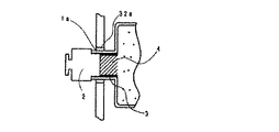
補給ユニット30が装置本体100に設けてあり、図7に示すように、現像剤補給容器1の装着部には容器本体1Aを支持し回転駆動を伝える駆動ローラ14が設けてある。具体的には、駆動ローラ14を支持する固定軸15がスタンド16に固定され、スタンド16は容器受け台50に固定されている。本例では、駆動モーター(不図示)からの駆動を駆動ローラ14に伝える構成になっている。駆動ローラ14は容器本体1Aに対して鞍形に配置して容器本体1Aを支持する位置にあり、容器本体1Aの回転軸線方向に2箇所配置してある。駆動ローラ14の数は4個である。容器本体1Aを安定して回転させることができれば、本例の構成に限定されることはなく、装置本体100と容器本体1Aの一部が係合して回転駆動力を容器本体1Aに伝達する構成であっても構わない。   A replenishment unit 30 is provided in the apparatus main body 100, and as shown in FIG. 7, a drive roller 14 that supports the container main body 1A and transmits rotational driving is provided in the mounting portion of the developer replenishment container 1. Specifically, the fixed shaft 15 that supports the driving roller 14 is fixed to the stand 16, and the stand 16 is fixed to the container receiving table 50. In this example, the drive motor 14 (not shown) transmits the drive to the drive roller 14. The drive roller 14 is disposed in a bowl shape with respect to the container main body 1A to support the container main body 1A, and is arranged at two locations in the rotation axis direction of the container main body 1A. The number of drive rollers 14 is four. As long as the container body 1A can be stably rotated, the configuration is not limited to the configuration of this example, and the apparatus body 100 and a part of the container body 1A are engaged to transmit the rotational driving force to the container body 1A. It may be a configuration.

補給ユニット30の現像剤補給容器1装着部の奥には穴32aを有する側板32が設けてある。穴32aはキャップ部材2が通り抜け可能な大きさを有している。   A side plate 32 having a hole 32 a is provided at the back of the developer supply container 1 mounting portion of the supply unit 30. The hole 32a has a size that allows the cap member 2 to pass through.

回転駆動部31は現像剤補給容器1の回転中心と平行な方向に移動ができる構造となっているため、回転駆動部31が係合部2bと係合した状態で前記方向に移動することにより、キャップ部材2と容器本体1Aを封止したり、開封したりすることができる。キャップ部材2の開閉は容器本体1Aの前側側面を側板32が、後ろ側側面を容器受け台50の一部(不図示)が支持することにより達成される。尚、現像剤補給容器1装着部を駆動ローラ14を有したホルダー状の部材(不図示)に構成しても良く、容器本体1Aに対するキャップ部材2の開閉時の力をホルダー状部材で受けるようにしても構わない。   Since the rotation drive unit 31 has a structure that can move in a direction parallel to the rotation center of the developer supply container 1, when the rotation drive unit 31 is engaged with the engagement unit 2b, The cap member 2 and the container main body 1A can be sealed or opened. The opening and closing of the cap member 2 is achieved by supporting the front side surface of the container main body 1A with the side plate 32 and supporting the rear side surface with a part (not shown) of the container cradle 50. Note that the developer supply container 1 mounting portion may be configured as a holder-like member (not shown) having a driving roller 14 so that the holder-like member receives the force when the cap member 2 is opened and closed with respect to the container body 1A. It doesn't matter.

補給ユニット30への現像剤補給容器1の装着は、図7においてキャップ部材2を先にして左行させるとキャップ部材2は側板32の穴32a を通り抜けて、現像剤排出開口1aが穴32aの位置にくると共に容器本体1Aは駆動ローラ14に支持される。このとき、回転駆動部31は図7において側板32に接近した位置にあり、且つ、上下2分割されている回転駆動部31は上下方向に互いに離れている。この回転駆動部31にキャップ部材2が位置した状態で、現像剤補給容器1の装着を検知したスイッチ(不図示)の投入により、自動で又は手動で、若しくは現像剤補給容器1を補給ユニット30の装着部へ装着後の装着部を開閉する容器交換用前カバー20と機械的に連動して回転駆動部31が半径方向に互いに接近し係合部31aがキャップ部材2の係合溝2b−1に嵌合する。   When the developer supply container 1 is attached to the supply unit 30, when the cap member 2 is moved to the left in FIG. 7, the cap member 2 passes through the hole 32a of the side plate 32, and the developer discharge opening 1a has the hole 32a. The container body 1 </ b> A is supported by the drive roller 14 as it comes to the position. At this time, the rotation drive unit 31 is in a position close to the side plate 32 in FIG. With the cap member 2 positioned on the rotation drive unit 31, a switch (not shown) that detects the mounting of the developer supply container 1 is turned on, automatically or manually, or the developer supply container 1 is supplied to the supply unit 30. The rotational drive parts 31 approach each other in the radial direction mechanically in conjunction with the container replacement front cover 20 that opens and closes the mounting part after being mounted on the mounting part, and the engaging part 31a engages with the engaging groove 2b- of the cap member 2. 1 is fitted.

係合部31aが係合溝2b−1に嵌合したことを不図示のスイッチが検知すると、回転駆動部31は図7において左行される。これによって、キャップ部材2の容器本体1Aに対する封止状態を解いて移動させ、キャップ部材2と現像剤排出開口1aとの間に現像剤排出経路fが確保される。このとき、図7に示す通り、キャップ部材2と現像剤排出開口1aとの間にはシート部材3が配置された状態のままになっており、実際に現像剤4が排出される経路はシート部材3の間の隙間になる。   When a switch (not shown) detects that the engaging portion 31a is fitted in the engaging groove 2b-1, the rotation driving portion 31 is moved to the left in FIG. As a result, the cap member 2 is unsealed and moved with respect to the container body 1A, and the developer discharge path f is secured between the cap member 2 and the developer discharge opening 1a. At this time, as shown in FIG. 7, the sheet member 3 remains in the state between the cap member 2 and the developer discharge opening 1a, and the path through which the developer 4 is actually discharged is the sheet. A gap is formed between the members 3.

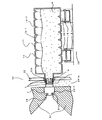
図8及び図9に本例のキャップ部材2の開封時の現像剤排出開口1aの円筒状部の現像剤の状態について示した。図8では、物流履歴を負ったり、キャップ部材2を下にした状態で長期間放置されたりして現像剤排出開口1aの現像剤4が圧密にされた状態を示している。   8 and 9 show the state of the developer in the cylindrical portion of the developer discharge opening 1a when the cap member 2 of this example is opened. FIG. 8 shows a state in which the developer 4 in the developer discharge opening 1a is consolidated by taking a distribution history or leaving the cap member 2 down for a long period of time.

本例の現像剤補給容器1は容器本体1Aの胴部1bの直径よりも現像剤排出開口1aの直径が小さいために現像剤排出開口1aの現像剤4は圧密になり易く、図8に示した現像剤4(斜線部)の密度は特に高くなる傾向がある。この状態で、キャップ部材2を開封するために左行させて容器本体1Aから離す方向に移動すると、図9に示した通り、キャップ部材2に設けたシート部材3の上に載った現像剤4がキャップ部材2と共に引きずり出される一方で、シート部材3が無い部分はそのままであるため、圧密された現像剤4が崩れる。その後、容器本体1A及びキャップ部材2を一緒に回転させると、崩れた現像剤4がシート部材3の間の隙間から現像ホッパー部201aに補給される。現像剤排出開口1a部に圧密された現像剤4を効果的に崩すには、シート部材3が現像剤排出開口1aの円筒内周に対して接触しているか限りなく近接していて、円筒内周と現像剤4の隙間に配置させ、開封時にシート部材3に載っている現像剤4を引張り出す必要がある。本例ではシート部材3と円筒内周との隙間を0.5mmに設定した。   In the developer supply container 1 of this example, the diameter of the developer discharge opening 1a is smaller than the diameter of the barrel 1b of the container main body 1A. Therefore, the developer 4 in the developer discharge opening 1a tends to become compact, and is shown in FIG. The density of developer 4 (shaded area) tends to be particularly high. In this state, when the cap member 2 is moved leftward to open the cap member 2 and moved away from the container main body 1A, the developer 4 placed on the sheet member 3 provided on the cap member 2 as shown in FIG. Is dragged out together with the cap member 2, while the portion without the sheet member 3 is left as it is, so that the compacted developer 4 is broken. Thereafter, when the container main body 1 </ b> A and the cap member 2 are rotated together, the broken developer 4 is supplied to the developing hopper 201 a from the gap between the sheet members 3. In order to effectively collapse the developer 4 compacted in the developer discharge opening 1a, the sheet member 3 is in close proximity to the cylindrical inner periphery of the developer discharge opening 1a as long as it is close to the cylinder. It is necessary to pull out the developer 4 placed on the sheet member 3 at the time of opening by disposing it in the gap between the circumference and the developer 4. In this example, the gap between the sheet member 3 and the inner periphery of the cylinder was set to 0.5 mm.

又、シート部材3の円筒内周に対する長さ、数について、本例では図6に示すように円筒内周を6分割するように、6箇所設けた。具体的には円筒内部直径30mmで内周30πmmを6分割して5πmmに対し、シート部材3のある領域と無い領域を均等に分けて、シート部材3の円弧状の長さは2.5πmmとした。このシート部材3の長さは、短く円筒内周に対する割合が少ないと開封時にシート部材3に載って引きずり出す現像剤4の量が減少してしまい、円筒内周の現像剤4を崩す効果が出にくくなる。逆に、長く円筒内周に対する割合が大きいとキャップ部材2開封時にシート部材3に載って引きずり出す量は多くなるが、圧密された現像剤4の塊を崩さずそのまま引きずり出してしまい、崩す効果が却って減少し、シート部材3の内部で崩れずに残ってしまう可能性がある。よって、本例ではシート部材3のある領域と無い領域を均等にしている。   Further, in this example, the length and number of the sheet member 3 with respect to the inner circumference of the cylinder are provided at six locations so that the inner circumference of the cylinder is divided into six as shown in FIG. Specifically, the inner diameter of the cylinder is 30 mm, and the inner circumference of 30 π mm is divided into 6 by dividing it into 5 π mm. The area with and without the sheet member 3 is equally divided, and the arc-shaped length of the sheet member 3 is 2.5 π mm. did. If the length of the sheet member 3 is short and the ratio to the inner circumference of the cylinder is small, the amount of the developer 4 that is dragged on the sheet member 3 at the time of opening is reduced, and the effect of breaking the developer 4 on the inner circumference of the cylinder is obtained. It becomes difficult. On the other hand, if the ratio to the inner circumference of the cylinder is long and large, the amount of dragging on the sheet member 3 when the cap member 2 is opened increases. There is a possibility that the sheet member 3 will remain without being broken inside the sheet member 3. Therefore, in this example, the area | region with the sheet member 3 and the area | region which does not exist are equalized.

又、シート部材3のキャップ部材2開閉方向に対する長さは、少なくとも現像剤排出開口1aの円筒部の長さ同等以上とし、キャップ部材2開封時に円筒内周部全長に渡って円筒部内の現像剤4を引きずり崩すことが望ましい。尚、キャップ部材2が完全に開封した時点で、シート部材3が現像剤排出開口1aから完全に離れても上記効果が得られれば構わないが、その際にはキャップ部材2閉時に確実に現像剤排出開口1aに収納される必要があり、できれば、シート部材3の一部を現像剤排出開口1aの中に残しておいた方が良い。この場合、現像剤補給容器1から排出される現像剤4はシート部材3の無い隙間からのみとなるため、シート部材3の円筒内周に対する長さ及びキャップ部材2の開閉方向に対する長さを調整することにより、補給量の定量化が図れたり、今回の現象とは全く逆の容器本体1A内部の現像剤4の密度が低下した状態で開封した際にもシート部材3が過度の排出を防止することで
フラッシング対策にも効果がある。本例ではシート部材3のキャップ部材2開閉方向に対する長さを30mmとし、現像剤排出開口1aの円筒全長に亘って配置した。更に、キャップ部材2の開封時の容器本体1Aに対する離間距離を20mmとし、シート部材3の一部を現像剤排出開口1a内部に残した構成とした。
Further, the length of the sheet member 3 in the cap member 2 opening / closing direction is at least equal to or longer than the length of the cylindrical portion of the developer discharge opening 1a, and the developer in the cylindrical portion covers the entire length of the inner peripheral portion of the cylinder when the cap member 2 is opened. It is desirable to drag 4 down. It should be noted that when the cap member 2 is completely opened, the above effect can be obtained even if the sheet member 3 is completely separated from the developer discharge opening 1a. It is necessary to be accommodated in the developer discharge opening 1a. If possible, it is better to leave a part of the sheet member 3 in the developer discharge opening 1a. In this case, since the developer 4 discharged from the developer supply container 1 is only from the gap without the sheet member 3, the length of the sheet member 3 with respect to the inner periphery of the cylinder and the length of the cap member 2 with respect to the opening / closing direction are adjusted. By doing so, the amount of replenishment can be quantified, or the sheet member 3 can be prevented from being excessively discharged even when opened in a state where the density of the developer 4 inside the container body 1A is completely opposite to the current phenomenon. By doing so, it is also effective against flashing. In this example, the length of the sheet member 3 with respect to the cap member 2 opening / closing direction is 30 mm, and the sheet member 3 is arranged over the entire cylindrical length of the developer discharge opening 1a. Further, the separation distance from the container main body 1A when the cap member 2 is opened is 20 mm, and a part of the sheet member 3 is left inside the developer discharge opening 1a.

以上、シート部材3の形状、寸法等は、本例に限定されるものではなく、使用する現像剤4の物性、現像剤排出開口1aの円筒部の寸法、形状等、実施の形態に合せて最も現像剤4の崩し効果が高い条件を選択することが望ましい。   As described above, the shape, dimensions, and the like of the sheet member 3 are not limited to the present example, and the physical properties of the developer 4 to be used, the dimensions, the shape, and the like of the cylindrical portion of the developer discharge opening 1a are matched to the embodiment. It is desirable to select a condition that has the highest breaking effect of the developer 4.

現像剤4補給時には、容器受け台50の駆動ローラ14が回転することにより容器本体1Aが回転し、同時に回転駆動部31が回転することによりキャップ部材2も回転する。容器本体1Aが回転すると、容器本体1Aの螺旋形状部1b−1により現像剤4が現像剤排出開口1a側に向かって送り出され、更に現像剤すくい上げ部1b−3により、現像剤排出開口1aに現像剤4が送られ、排出経路fを通って現像ホッパー部201aに現像剤4が供給される。本実施の形態では、容器本体1Aが現像剤4を収納する容器本体と現像剤4を搬送する現像剤搬送部材を兼ねているものである。   When the developer 4 is replenished, the container main body 1A is rotated by the rotation of the drive roller 14 of the container cradle 50, and the cap member 2 is also rotated by the rotation of the rotation drive unit 31 at the same time. When the container main body 1A rotates, the developer 4 is sent out toward the developer discharge opening 1a by the spiral-shaped part 1b-1 of the container main body 1A, and further, the developer scooping part 1b-3 moves to the developer discharge opening 1a. The developer 4 is sent, and the developer 4 is supplied to the developing hopper 201a through the discharge path f. In the present embodiment, the container main body 1 </ b> A also serves as a container main body that stores the developer 4 and a developer transport member that transports the developer 4.

現像ホッパー部201aが十分に現像剤4で満たされると、容器本体1Aの回転を停止することにより、現像剤4の供給を止めることができる。容器本体1Aの回転速度、回転数は現像ホッパー部201aの容量や残検量の設定等によって変わるため、適切な設定を行う必要がある。又、キャップ部材2についても、容器本体1Aと同じ速度で回転させることが望ましい。容器本体1Aとキャップ部材2が同速度で回転すれば、現像剤排出開口1aとシート部材3は相対的に移動することはなく、キャップ部材2の回転トルクがアップしたり、現像剤排出開口1aとシート部材3とが摺擦して粗大粒子が発生する可能性はなくなる。   When the developing hopper 201a is sufficiently filled with the developer 4, the supply of the developer 4 can be stopped by stopping the rotation of the container body 1A. Since the rotation speed and rotation speed of the container main body 1A vary depending on the capacity of the developing hopper 201a and the setting of the residual amount, it is necessary to make appropriate settings. Moreover, it is desirable to rotate the cap member 2 at the same speed as the container main body 1A. If the container body 1A and the cap member 2 rotate at the same speed, the developer discharge opening 1a and the sheet member 3 do not move relative to each other, and the rotational torque of the cap member 2 increases or the developer discharge opening 1a. There is no possibility that coarse particles are generated due to the friction between the sheet member 3 and the sheet member 3.

現像剤4の補給が終了し、容器本体1Aの現像剤4が無くなったら、補給ユニット30の回転駆動部31が回転中心線方向に移動してキャップ部材2を容器本体1Aに装着させ、再び現像剤排出開口1aを封止する。その後、回転駆動部31が半径方向に移動し、キャップ部材2の係合溝2b−1と回転駆動部31の係合部31a は外れる。   When the replenishment of the developer 4 is completed and the developer 4 in the container body 1A runs out, the rotation drive unit 31 of the replenishment unit 30 moves in the direction of the rotation center line to attach the cap member 2 to the container body 1A and develop again. The agent discharge opening 1a is sealed. Thereafter, the rotation drive part 31 moves in the radial direction, and the engagement groove 2b-1 of the cap member 2 and the engagement part 31a of the rotation drive part 31 are released.

尚、キャップ部材2の開閉時には、キャップ部材2が移動しても容器本体1Aが移動しても構わず、補給ユニット30の機構との関係で選択することができる。又、本例の現像剤補給容器1は、キャップ部材2、容器本体1Aの現像剤排出開口1aの現像剤排出経路f以外の部分を補給ユニット30に覆われているため、現像剤4補給時の汚れは非常に少ない。   When the cap member 2 is opened and closed, the cap member 2 may move or the container body 1A may move, and the selection can be made in relation to the mechanism of the replenishment unit 30. Further, since the developer supply container 1 of this example is covered with the supply unit 30 except for the developer discharge path f of the developer discharge opening 1a of the cap member 2 and the container body 1A, when the developer 4 is supplied. There is very little dirt.

実際に、本実施例の現像剤補給容器1を用いて現像剤4補給を行ったところ、現像剤4の補給は良好であり、現像剤4補給後の容器本体1Aの現像剤4残量は10g以下であった。   Actually, when the developer 4 was replenished using the developer replenishing container 1 of this embodiment, the developer 4 was replenished well, and the remaining amount of the developer 4 in the container body 1A after replenishing the developer 4 was It was 10 g or less.

又、最悪時を想定した物流、環境テストとして、現像剤補給容器1の物流梱包状態で振動、衝撃等を加えて容器本体1A内部の現像剤4を圧密状態にしたり、キャップ部材2を下にした状態で長期保管した状態での開封、排出テストを行ったが、特に異常は見られず、現像剤4の補給性能も良好であった。   Further, as a logistics / environment test in the worst case, the developer 4 inside the container main body 1A is brought into a compacted state by applying vibrations, shocks, etc. in the logistics packaging state of the developer supply container 1, or the cap member 2 is placed downward. In this state, opening and discharging tests were performed in a state of long-term storage, but no abnormality was found and the developer 4 replenishment performance was good.

尚、本実施の形態は上記構成に限定されるものではなく、例えば変形例として、容器本体1Aに螺旋形状部1b−1を設けずに、別体の搬送部材を容器本体1A内部に保持し、容器本体1Aと共に回転して現像剤4を排出供給するといった構成でも可能であり、本例の効果が得られる範囲で、構成を自由に選択することができる。   The present embodiment is not limited to the above configuration. For example, as a modification, the container body 1A is not provided with the spiral portion 1b-1, and a separate transport member is held inside the container body 1A. Also, a configuration in which the developer 4 is discharged and supplied together with the container body 1A is possible, and the configuration can be freely selected within a range in which the effect of the present example can be obtained.

<実施の形態2>
本実施の形態に係る現像剤補給容器1の構成を図10に示す。
<Embodiment 2>
FIG. 10 shows the configuration of the developer supply container 1 according to this embodiment.

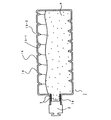
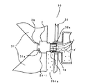
本実施の形態に係る現像剤補給容器1は、主に容器本体1A、キャップ部材2、シート部材3、搬送部材10、フランジ11から成っている。図10に示した通り、実施例1と異なり円筒状の容器本体1A内部に搬送部材10を設けており、容器本体1Aの現像剤排出開口1aとは反対側の端面にフランジ11を設けてある。   The developer supply container 1 according to the present embodiment mainly includes a container main body 1A, a cap member 2, a sheet member 3, a conveying member 10, and a flange 11. As shown in FIG. 10, unlike Example 1, the conveying member 10 is provided inside the cylindrical container body 1A, and the flange 11 is provided on the end surface of the container body 1A opposite to the developer discharge opening 1a. .

又、キャップ部材2には容器本体1Aの現像剤排出開口1aの内部と係合する爪部材2cを設けており、補給ユニット30から受けた回転駆動を爪部材2cを介して容器本体1Aに伝達し、容器本体1Aをキャップ部材2と一緒に回転させる構成になっている。   The cap member 2 is provided with a claw member 2c that engages with the inside of the developer discharge opening 1a of the container main body 1A, and the rotational drive received from the replenishment unit 30 is transmitted to the container main body 1A via the claw member 2c. The container body 1 </ b> A is rotated together with the cap member 2.

本実施の形態の各部品について説明する。   Each component of the present embodiment will be described.

容器本体1Aは実施の形態1と異なり、螺旋等が無い円筒形状であり、現像剤排出開口1aと反対側の端面は搬送部材10を挿入した後、フランジ11を組み付けるために円状の開口を有している。現像剤排出開口1aには、キャップ部材2の爪部材2cと係合して回転駆動を伝達するリブ状の突起1a−1を設けてある。材質等については実施の形態1と同様であるが、本例ではポリスチレンを用いて射出成型にて成型した。   Unlike the first embodiment, the container main body 1A has a cylindrical shape without a spiral or the like, and the end surface opposite to the developer discharge opening 1a has a circular opening for assembling the flange 11 after the conveying member 10 is inserted. Have. The developer discharge opening 1 a is provided with a rib-like protrusion 1 a-1 that engages with the claw member 2 c of the cap member 2 and transmits rotational driving. The material and the like are the same as in the first embodiment, but in this example, it was molded by injection molding using polystyrene.

搬送部材10は容器本体1A内部に挿入され、容器本体1Aと一緒に回転し容器本体1A内部の現像剤4を現像剤排出開口1aに向けて搬送するためのものである。図10に示した通り、円筒状の容器本体1Aの断面の円形状を回転軸線方向に沿って2分割するような平板部10aと、回転時に現像剤4をすくって搬送するための傾斜板10bから成り、平板部10aはその一部が容器本体1Aと係合して一緒に回転し、更に現像剤4のブリッジ防止や流動を妨げないように部分部分に開口を有している。   The conveying member 10 is inserted into the container main body 1A and rotates together with the container main body 1A to convey the developer 4 inside the container main body 1A toward the developer discharge opening 1a. As shown in FIG. 10, a flat plate portion 10a that divides the circular shape of the cylindrical container body 1A into two along the rotation axis direction, and an inclined plate 10b for scooping and transporting the developer 4 during rotation. The flat plate portion 10a is partially engaged with the container body 1A and rotates together, and further has an opening in the portion so as not to prevent the bridging and flow of the developer 4.

傾斜板10bは、平板部10aの回転軸線方向に対し一定間隔で約45°の角度で取り付けてあり、容器本体1A回転時には容器本体1Aの底側に溜まった現像剤4を傾斜板10bに載せて容器本体1A回転に伴い傾斜に沿って現像剤4を滑らせて現像剤排出開口1aに向けて送る構成になっている。現像剤排出開口1aに最も近い傾斜板10bは現像剤排出開口1aの円筒部に直接現像剤4を搬送するように円筒部内に侵入若しくは現像剤排出口開口1aと容器本体1Aの胴部1bの境界に近接させている。搬送部材10として、上記目的が達成できる範囲であれば、材質、形状、寸法を自由に選択できるが、本例では、肉厚1.5mmのポリスチレンを用いた。   The inclined plate 10b is attached at an angle of about 45 ° at regular intervals with respect to the rotation axis direction of the flat plate portion 10a, and the developer 4 accumulated on the bottom side of the container body 1A is placed on the inclined plate 10b when the container body 1A rotates. Thus, the developer 4 is slid along the inclination along with the rotation of the container body 1A and sent toward the developer discharge opening 1a. The inclined plate 10b closest to the developer discharge opening 1a penetrates into the cylindrical portion so as to convey the developer 4 directly to the cylindrical portion of the developer discharge opening 1a or between the developer discharge port opening 1a and the body portion 1b of the container main body 1A. It is close to the boundary. The material, shape, and dimensions can be freely selected as the conveying member 10 as long as the above object can be achieved. In this example, polystyrene having a wall thickness of 1.5 mm was used.

フランジ11は、容器本体1Aに搬送部材10を挿入した後、容器本体1Aの開口を塞ぎ、搬送部材10の容器本体1A内部の固定をサポートするためのもであり、容器本体1Aに対し、接着、溶着等の手段で組み立てる。本例では容器本体1Aと同様、ポリスチレンで射出成型し、容器本体1Aには超音波溶着にて固定した。   The flange 11 is for closing the opening of the container main body 1A after the conveyance member 10 is inserted into the container main body 1A and supporting the fixing of the conveyance member 10 inside the container main body 1A. Assemble by means such as welding. In this example, similarly to the container main body 1A, it was injection-molded with polystyrene and fixed to the container main body 1A by ultrasonic welding.

キャップ部材2は、回転駆動を伝達するための爪部材2cを設けた以外は実施の形態1と同じである。図11に示したように、本例では容器本体1Aの現像剤排出開口1aのリブ状突起1a−1と係合するように円周方向に沿って180°方向に対向するように2箇所に爪部材2cを設けた。更に、シート部材3については、実施の形態1と同様、6箇所配置のシート部材のうち2箇所を爪部材2cで対応するものとし、それ以外に4箇所設けた。   The cap member 2 is the same as that of the first embodiment except that a claw member 2c for transmitting rotational driving is provided. As shown in FIG. 11, in this example, two positions are provided so as to face the 180 ° direction along the circumferential direction so as to engage with the rib-like protrusions 1a-1 of the developer discharge opening 1a of the container main body 1A. A claw member 2c was provided. Furthermore, about the sheet | seat member 3, like the Embodiment 1, 2 places shall correspond by the nail | claw member 2c among the sheet members of 6 places arrangement | positioning, and provided 4 places other than that.

次に、本例の現像剤補給容器1の組立方法について説明する。   Next, an assembling method of the developer supply container 1 of this example will be described.

前述したように、容器本体1Aに搬送部材10を挿入、組み付けてからフランジ11を容器本体1Aに超音波溶着にて溶着する。その後、現像剤排出開口1aから現像剤4を充填し、最後にシート部材3を設けたキャップ部材2を現像剤排出開口1aに嵌めて封止する。尚、本例の現像剤補給容器1は上記の組立方法に限定されるものではなく、例えば、搬送部材10の組み付けについて、フランジ11に搬送部材10を組み込んでから容器本体1Aに組み付けても良く、又、現像剤4の充填について、充填口をフランジ11に設けて、容器本体1Aに搬送部材10、フランジ11、キャップ部材2を組付けた後、充填口から現像剤4を充填し、封止部材で充填口を封止しても構わない。   As described above, after the conveying member 10 is inserted and assembled into the container body 1A, the flange 11 is welded to the container body 1A by ultrasonic welding. Thereafter, the developer 4 is filled from the developer discharge opening 1a, and finally the cap member 2 provided with the sheet member 3 is fitted into the developer discharge opening 1a and sealed. Note that the developer supply container 1 of this example is not limited to the above assembly method. For example, the assembly of the transport member 10 may be performed after the transport member 10 is assembled into the flange 11 and then assembled into the container body 1A. In addition, for filling the developer 4, a filling port is provided in the flange 11, and after the conveying member 10, the flange 11, and the cap member 2 are assembled to the container body 1 </ b> A, the developer 4 is filled from the filling port and sealed. The filling port may be sealed with a stop member.

次に、現像剤補給操作について説明する。   Next, a developer replenishing operation will be described.

本例の現像剤補給の状況を図12に示す。   FIG. 12 shows the status of developer replenishment in this example.

基本的には、実施の形態1と同様、補給ユニット30の容器装着部に現像剤補給容器1を装着して、補給ユニット30の回転駆動部31がキャップ部材2と係合して、キャップ部材2を容器本体1Aから離間させて開封させる。その後、回転駆動部31からキャップ部材2が回転駆動を受けて回転するが、本例では、このとき、キャップ部材2の爪部材2cが容器本体1Aの現像剤排出開口1aの円筒内部に設けたリブ状突起1a−1と係合することにより、容器本体1Aに回転駆動を伝達し一緒に回転する構成となっている。   Basically, as in the first embodiment, the developer supply container 1 is mounted on the container mounting portion of the supply unit 30, and the rotation drive unit 31 of the supply unit 30 is engaged with the cap member 2, so that the cap member 2 is opened apart from the container body 1A. Thereafter, the cap member 2 is rotated by receiving the rotational drive from the rotational drive unit 31. In this example, the claw member 2c of the cap member 2 is provided inside the cylinder of the developer discharge opening 1a of the container body 1A. By engaging with the rib-like protrusion 1a-1, the rotation drive is transmitted to the container main body 1A to rotate together.

よって、実施の形態1とは異なり、容器本体1Aを別の駆動源で回転する必要はなく、駆動モーターが不要になるメリットがある。キャップ部材2と一緒に容器本体1Aが回転すると容器本体1A内部に配置した搬送部材10によって容器本体1A内部の現像剤4が現像剤排出開口1aに向かって搬送され、その後現像剤排出開口1aから現像ホッパー201aに向かって排出される。本実施の形態についても、実施の形態1と同様、キャップ部材2開封時に、シート部材3と爪部材2cによって、現像剤排出開口1aの円筒部内の現像剤4を引きずり出して崩すことができるため、円筒内部の現像剤4が圧密された状態になっても確実に崩して補給することができる。又、実施の形態1と同様、キャップ部材2の爪部材2c及びシート部材3と容器本体1Aの現像剤排出開口1aが一緒に回転して摺擦することがないため、キャップ部材2の回転トルクがアップしたり、粗大粒子が発生する可能性はない。   Therefore, unlike Embodiment 1, there is no need to rotate the container main body 1A with another drive source, and there is an advantage that a drive motor is not required. When the container main body 1A rotates together with the cap member 2, the developer 4 inside the container main body 1A is conveyed toward the developer discharge opening 1a by the conveying member 10 arranged inside the container main body 1A, and then from the developer discharge opening 1a. It is discharged toward the developing hopper 201a. Also in the present embodiment, similar to the first embodiment, when the cap member 2 is opened, the developer 4 in the cylindrical portion of the developer discharge opening 1a can be dragged out by the sheet member 3 and the claw member 2c, so that it can be broken. Even if the developer 4 inside the cylinder is in a compacted state, it can be reliably broken down and replenished. Similarly to the first embodiment, the claw member 2c and the sheet member 3 of the cap member 2 and the developer discharge opening 1a of the container main body 1A are not rotated and rubbed together. There is no possibility of increasing the size or generating coarse particles.

現像剤4の補給が終了し、容器本体1A内の現像剤4が無くなると、実施の形態1と同様、キャップ部材2を容器本体1Aに装着させて、現像剤排出開口1aを封止し、キャップ部材2と回転駆動部31との係合を解除する。   When the replenishment of the developer 4 is completed and the developer 4 in the container body 1A is exhausted, the cap member 2 is attached to the container body 1A and the developer discharge opening 1a is sealed, as in the first embodiment, The engagement between the cap member 2 and the rotation drive unit 31 is released.

実際に、本実施の形態についても現像剤補給容器1を用いて現像剤補給を行ったところ、現像剤4の補給は良好であり、現像剤補給後の容器本体1Aの現像剤残量は10g以下であった。   Actually, also in this embodiment, when the developer replenishment container 1 is used to replenish the developer, the developer 4 is replenished well, and the remaining amount of the developer in the container body 1A after the replenishment of the developer is 10 g. It was the following.

又、最悪時を想定した物流、環境テストとして、現像剤補給容器1の物流梱包状態で振動、衝撃等を加えて容器本体1a内部の現像剤4を圧密状態にしたり、キャップ部材2を下にした状態で長期保管した状態での開封、排出テストを行ったが、特に異常は見られず、現像剤4の補給性能も良好であった。   Further, as a logistics and environmental test assuming the worst case, the developer 4 inside the container main body 1a is brought into a compacted state by applying vibration, impact, etc. in the logistics packaging state of the developer supply container 1, or the cap member 2 is placed below. In this state, opening and discharging tests were performed in a state of long-term storage, but no abnormality was found and the developer 4 replenishment performance was good.

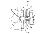
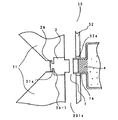
尚、本実施の形態は上記の構成に限定されるものではなく、例えば変形例として、図13に示したように、搬送部材10から角軸を出し、角軸とキャップ部材2が係合状態を維持した状態でキャップ部材2が開閉し、キャップ部材2に回転駆動が伝達された後、角軸を介して搬送部材10及び容器本体1Aを回転させて、現像剤4を補給するといった構成も可能であり、又、係合し回転駆動を伝達できれば角軸でなくても構わず、本発明の効果が得られる範囲で、構成を自由に選択できる。   The present embodiment is not limited to the above-described configuration. For example, as shown in FIG. 13, as a modification, the angular axis is projected from the conveying member 10, and the angular axis and the cap member 2 are engaged. The cap member 2 is opened and closed in a state where the above-described conditions are maintained, and after the rotational drive is transmitted to the cap member 2, the conveying member 10 and the container main body 1A are rotated via the angular axis to replenish the developer 4. If it is possible and it can engage and transmit rotational drive, it does not have to be a square axis, and the configuration can be freely selected within the range where the effects of the present invention can be obtained.

<実施の形態3>
本実施の形態は、シート部材3に可撓性のある厚さ100μmのポリエステルのシートを用いた以外は、実施の形態1,2と同じである。本例のシート部材3は、実施の形態1,2に対し、可撓性のある材料であるため、図14に示した通り、キャップ部材2開封時及び現像剤補給時に適度に撓みと跳ね返り等の変形を繰り返し、圧密された現像剤4を崩す効果が高くなり、より確実に現像剤4を安定して補給することが可能になる。上記効果が得られる範囲であれば、用いる現像剤4の密度、現像剤排出開口1aの寸法、形状等により適切な材質(例えば、ポリエチレン、ポリプロピレン、ウレタン、シリコーン等)、厚み等を選択することができる。又、材質にエラストマーを用いてキャップ部材2と2色成型する構成も考えられるが、より低コストで安定した品質を得ることができるため望ましい。
<Embodiment 3>
The present embodiment is the same as the first and second embodiments except that a flexible polyester sheet having a thickness of 100 μm is used for the sheet member 3. Since the sheet member 3 of this example is a flexible material as compared with the first and second embodiments, as shown in FIG. 14, the sheet member 3 is appropriately bent and rebounded when the cap member 2 is opened and when the developer is replenished. The effect of breaking the compacted developer 4 is increased and the developer 4 can be replenished more reliably and stably. As long as the above effects can be obtained, an appropriate material (for example, polyethylene, polypropylene, urethane, silicone, etc.), thickness, etc., should be selected depending on the density of the developer 4 to be used and the dimensions and shape of the developer discharge opening 1a. Can do. Moreover, although the structure which shape-molds with the cap member 2 using an elastomer as a material is also considered, since stable quality can be obtained at lower cost, it is desirable.

実際に、本実施の形態についても現像剤補給容器1を用いて現像剤補給を行ったところ、現像剤4の補給は良好であり、現像剤4補給後の容器本体1Aの現像剤4残量は10g以下であった。   Actually, also in this embodiment, when the developer replenishment container 1 is used to replenish the developer, the replenishment of the developer 4 is good, and the remaining amount of the developer 4 in the container main body 1A after the replenishment of the developer 4 is achieved. Was 10 g or less.

又、最悪時を想定した物流、環境テストとして、現像剤補給容器1の物流梱包状態で振動、衝撃等を加えて容器本体1A内部の現像剤4を圧密状態にしたり、キャップ部材2を下にした状態で長期保管した状態での開封、排出テストを行ったが、特に異常は見られず、現像剤4の補給性能も良好であった。   Further, as a logistics / environment test in the worst case, the developer 4 inside the container main body 1A is brought into a compacted state by applying vibrations, shocks, etc. in the logistics packaging state of the developer supply container 1, or the cap member 2 is placed downward. In this state, opening and discharging tests were performed in a state of long-term storage, but no abnormality was found, and the developer 4 replenishment performance was also good.

更に、排出性能のマージンを確認するために、通常の物流、保管状態ではあり得ないレベルだが、キャップ部材2を下にした状態で現像剤補給容器1に軽い落下衝撃を連続で加えてサチッた状態での排出テストを行ったが、シート部材3の変形により、現像剤排出開口1a内部の現像剤4が確実に崩され、安定した補給を行うことができた。   Furthermore, in order to confirm the margin of the discharge performance, it is a level that cannot be in the normal physical distribution and storage state, but it was satisfactorily applied by continuously applying a light drop impact to the developer supply container 1 with the cap member 2 down. As a result of the discharge test in the state, the developer 4 inside the developer discharge opening 1a was reliably broken by the deformation of the sheet member 3, and stable replenishment could be performed.

(比較例1)
本例は、実施の形態1において、シート部材3が無い例であり、それ以外は実施の形態1と同じである。本例についても、最悪時を想定した物流、環境テストとして、現像剤補給容器1の物流梱包状態で振動、衝撃を加えて容器本体1A内部の現像剤4を圧密状態にしたり、キャップ部材2を下にした状態で長期保管した状態の開封、排出テストを行ったが、図15に示した通り、容器本体1Aの現像剤排出開口1aに圧密された現像剤4は、全く崩れず排出することができなかった。同じ条件で排出させるために、現像剤排出開口1aの直径を大きくしなければならず、キャップ部材2のシール性の低下を招いたり、逆にキャップ部材2の開閉強度がアップしてしまう問題が生じ易くなった。尚、実施の形態1の変形例も同様の結果であった。
(Comparative Example 1)
This example is an example in which the sheet member 3 is not provided in the first embodiment, and other than that is the same as the first embodiment. Also in this example, as a logistics and environmental test assuming the worst case, the developer 4 inside the container main body 1A is brought into a compacted state by applying vibration and impact in the logistics packaging state of the developer supply container 1, or the cap member 2 is The unsealed and discharged test was performed for a long period of time in the down state, but as shown in FIG. 15, the developer 4 compacted in the developer discharge opening 1a of the container body 1A should be discharged without collapse. I could not. In order to discharge under the same conditions, the diameter of the developer discharge opening 1a must be increased, resulting in a problem that the sealing performance of the cap member 2 is lowered, and conversely, the opening / closing strength of the cap member 2 is increased. It became easy to occur. The modified example of the first embodiment has similar results.

(比較例2)
本例は、実施の形態2において、シート部材3が無い例であり、それ以外は実施の形態2と同じである。本例の場合、キャップ部材2に回転駆動伝達のための爪部材2cが設けてある。
(Comparative Example 2)
This example is an example in which the sheet member 3 is not provided in the second embodiment, and other than that is the same as the second embodiment. In the case of this example, the cap member 2 is provided with a claw member 2c for rotational drive transmission.

本例についても、最悪時を想定した物流、環境テストとして、現像剤補給容器1の物流梱包状態で振動、衝撃を加えて容器本体1A内部の現像剤4を圧密状態にしたり、キャップ部材2を下にした状態で長期保管した状態の開封、排出テストを行った。キャップ部材2開封時に、爪部材2cが現像剤排出開口1aの円筒内部で回転軸線方向に動くことにより、円筒内部の現像剤4の一部を崩すことができ、何とか排出することはできた。   Also in this example, as a logistics and environmental test assuming the worst case, the developer 4 inside the container main body 1A is brought into a compacted state by applying vibration and impact in the logistics packaging state of the developer supply container 1, or the cap member 2 is Opening and discharging tests were conducted in the state of being stored for a long time in the down state. When the cap member 2 was opened, the claw member 2c moved in the direction of the rotation axis inside the cylinder of the developer discharge opening 1a, so that a part of the developer 4 inside the cylinder could be broken down and discharged somehow.

しかしながら、実施の形態2に対し、シート部材3が無いために、現像剤排出開口1aの円筒部内の現像剤4の一部しか崩せず、現像剤4が凝集し易い物性であったり、通常の物流、保管状態ではあり得ないイレギュラーなレベルで圧密された場合には、排出できない場合があった。   However, since the sheet member 3 is not provided in the second embodiment, only a part of the developer 4 in the cylindrical portion of the developer discharge opening 1a is collapsed, and the developer 4 is easy to aggregate. When compacted at an irregular level that cannot be in the state of physical distribution or storage, there were cases where it could not be discharged.

尚、実施の形態2の変形例についても、本例のようにシート部材3が無い状態で排出テストを行った結果、実施の形態2のように現像剤排出開口1aの円筒内部で回転軸線方向に動く爪部材2cが無いだけでなく、搬送部材10から出た角軸が円筒内部を貫き円筒内部の空間を埋めているために、現像剤4がよりブリッジし易く、円筒内部の現像剤4は崩れず、排出性は悪化してしまった。   As for the modification of the second embodiment, the discharge test is performed without the sheet member 3 as in this example, and as a result, the rotation axis direction is within the cylinder of the developer discharge opening 1a as in the second embodiment. In addition, there is no claw member 2c that moves in a straight line, and since the square axis coming out of the conveying member 10 penetrates the inside of the cylinder and fills the space inside the cylinder, the developer 4 is more easily bridged, and the developer 4 inside the cylinder The emissions did not collapse and the emissions were worse.

(比較例3)
本例は、実施の形態1のキャップ部材2に解し部材5を設け、現像剤補給時には容器本体1Aとキャップ部材2を相対的に回転させた以外は実施の形態1と同じである。本例の現像剤補給容器1の現像剤補給状態を図16に示す。
(Comparative Example 3)
This example is the same as the first embodiment except that the disassembling member 5 is provided in the cap member 2 of the first embodiment, and the container body 1A and the cap member 2 are relatively rotated when the developer is replenished. FIG. 16 shows the developer supply state of the developer supply container 1 of this example.

本例では、容器本体1Aの現像剤排出開口1aの円筒内の現像剤4をキャップ部材2の解し部材5で崩して排出させる構成である。現像剤補給時は、容器本体1Aとキャップ部材2を回転させて行うが、相対的に回転させるべく、互いを逆方向に回転させるか、回転速度に差をつけて回転させる構成であり、本例では逆方向に回転させた。   In this example, the developer 4 in the cylinder of the developer discharge opening 1 a of the container main body 1 </ b> A is broken by the opening member 5 of the cap member 2 and discharged. When the developer is replenished, the container main body 1A and the cap member 2 are rotated, but in order to relatively rotate, the container main body 1A and the cap member 2 are rotated in opposite directions or with different rotational speeds. In the example, it was rotated in the reverse direction.

本例についても、最悪時を想定した物流、環境テストとして、現像剤補給容器1の物流梱包状態で振動、衝撃を加えて容器本体1A内部の現像剤4を圧密状態にしたり、キャップ部材2を下にした状態で長期保管した状態の開封、排出テストを行った。現像剤排出開口1aの円筒内部に圧密された現像剤4はキャップ部材2の解し部材5により崩され排出させることはできたが、キャップ部材2の回転トルクがアップしてしまい、対策として解し部材5の剛性を低下させたが、その場合には、解し部材5が圧密された現像剤4に負けて変形してしまい、解し効果が弱くなってしまう場合があった。   Also in this example, as a logistics and environmental test assuming the worst case, the developer 4 inside the container main body 1A is brought into a compacted state by applying vibration and impact in the logistics packaging state of the developer supply container 1, or the cap member 2 is Opening and discharging tests were conducted in the state of being stored for a long time in the down state. Although the developer 4 compacted inside the cylinder of the developer discharge opening 1a could be broken and discharged by the unscrewing member 5 of the cap member 2, the rotational torque of the cap member 2 is increased, which is a countermeasure. However, in this case, the unraveling member 5 may be deformed by being defeated by the consolidated developer 4, and the unraveling effect may be weakened.

本発明の実施の形態に設けたシート部材3のように現像剤排出開口1aの円筒内周に沿って配置し、開封時に移動するだけで面で崩す構成とは異なり、本例は平面の解し部材5であるために開封時に移動する時には円筒内面に対し線でしか崩せない。よって、本例の場合は容器本体1Aとキャップ部材2が相対回転することが必須条件であり、上記の問題点が生じる場合があった。   Unlike the configuration in which the sheet member 3 provided in the embodiment of the present invention is arranged along the cylindrical inner periphery of the developer discharge opening 1a and is simply moved at the time of opening, the surface is broken. Since it is the support member 5, when it moves at the time of opening, it can only be broken by a line with respect to the inner surface of the cylinder. Therefore, in the case of this example, it is an essential condition that the container body 1A and the cap member 2 rotate relative to each other, and the above-described problem may occur.

更に、本例において、より確実に現像剤排出開口1aの円筒内部の現像剤4を解して排出させるために、キャップ部材2開封状態で解し部材5を円筒内周面に摺擦させる構成にした時には、摺擦部から粗大粒子が発生してしまい、そのまま現像ホッパー部201aに混入して、最終的には、スジやポチ等の画像不良を引き起こしてしまう場合があった。   Furthermore, in this example, in order to unleash and discharge the developer 4 inside the cylinder of the developer discharge opening 1a more reliably, the structure is rubbed against the inner circumferential surface of the cylinder 5 when the cap member 2 is opened. In such a case, coarse particles are generated from the rubbing portion and mixed into the developing hopper portion 201a as they are, which may eventually cause image defects such as streaks and spots.

画像形成装置全体の構成を示す断面図である。1 is a cross-sectional view illustrating a configuration of an entire image forming apparatus. 画像形成装置全体を示す斜視図である。1 is a perspective view showing an entire image forming apparatus. 現像剤補給容器を画像形成装置に着脱する様子を示す斜視図である。FIG. 3 is a perspective view showing a state where a developer supply container is attached to and detached from the image forming apparatus. 本発明の実施の形態1に係る現像剤補給容器の構成を示す断面図である。FIG. 3 is a cross-sectional view illustrating a configuration of a developer supply container according to Embodiment 1 of the present invention. 本発明の実施の形態1に係る現像剤補給容器の構成を示す平面図である。FIG. 2 is a plan view showing a configuration of a developer supply container according to Embodiment 1 of the present invention. (a)本発明の実施の形態1のキャップ部材の構成を示す斜視図、(b)キャップ部材の構成を示す平面図である。(A) It is a perspective view which shows the structure of the cap member of Embodiment 1 of this invention, (b) It is a top view which shows the structure of a cap member. 本発明の実施の形態1に係る現像剤補給容器の現像剤補給の状態を示す断面図である。FIG. 6 is a cross-sectional view showing a state of developer supply in the developer supply container according to Embodiment 1 of the present invention. 本発明の実施の形態1に係る現像剤補給容器の現像剤補給前の状態を示す部分断面図である。FIG. 3 is a partial cross-sectional view showing a state before developer supply in the developer supply container according to Embodiment 1 of the present invention. 本発明の実施の形態1に係る現像剤補給容器のキャップ部材開封時の状態を示す部分断面図である。FIG. 6 is a partial cross-sectional view showing a state when the cap member of the developer supply container according to Embodiment 1 of the present invention is opened. 本発明の実施の形態2に係る現像剤補給容器の構成を示す断面図である。It is sectional drawing which shows the structure of the developer supply container which concerns on Embodiment 2 of this invention. 本発明の実施の形態2実施例2のキャップ部材の構成を示す斜視図、(b)キャップ部材の構成を示す平面図である。Embodiment 2 of the Present Invention A perspective view showing a configuration of a cap member of Example 2 of the present invention, (b) a plan view showing a configuration of the cap member. 本発明の実施の形態に係る現像剤補給容器の現像剤の補給状態を示す断面図である。FIG. 6 is a cross-sectional view showing a developer supply state of the developer supply container according to the embodiment of the present invention. 本発明の実施の形態2の変形例に係る現像剤補給容器の構成を示す断面図である。It is sectional drawing which shows the structure of the developer supply container which concerns on the modification of Embodiment 2 of this invention. 本発明の実施の形態3に係る現像剤補給容器のキャップ部材開封時の状態を示す部分断面図である。It is a fragmentary sectional view which shows the state at the time of cap member opening of the developer supply container which concerns on Embodiment 3 of this invention. 比較例1の現像剤補給容器のキャップ部材の開封時の状態を示す部分断面図である。6 is a partial cross-sectional view showing a state when a cap member of a developer supply container of Comparative Example 1 is opened. FIG. 比較例3の現像剤補給容器の現像剤の補給状態を示す断面図である。10 is a cross-sectional view illustrating a developer supply state in a developer supply container of Comparative Example 3. FIG.

符号の説明Explanation of symbols

Ln レンズ
M ミラー
P 媒体
1 現像剤補給容器
1A 容器本体
1a 現像剤排出開口
1a−1 リブ状突起
1b 胴部
1b−1 螺旋形状部
1b−2 溝
1b−3 すくい上げ部
2 キャップ部材
2a 封止部
2a−1 リブ
2b 係合部
2b−1 係合溝
2c 爪部材
3 シート部材
4 現像剤
5 解し部材
10 搬送部材
10a 平板部
10b 傾斜板
11 フランジ
14 駆動ローラ
15 固定軸
16 スタンド
18 ヒンジ
20 現像剤補給容器交換用前カバー
30 補給ユニット
31 回転駆動部
31a 係合部
32 側板
32a 穴
50 容器受け台
100 装置本体
100a 操作部
100b 表示手段
100c 前面カバー
101 原稿
102 原稿台ガラス
103 光学部
104 感光体ドラム
105 カセット
105A 給送・分離装置
106 カセット
106A 給送・分離装置
107 カセット
107A 給送・分離装置
108 カセット
108 A給送・分離装置
109 搬送部
110 レジストローラ
111 転写放電器
112 分離放電器
113 搬送部
114 定着部
115 排出反転部
116 排出ローラ
117 排出トレイ
118 フラッパ
119 再給送搬送路
120 再給送搬送路
201 現像装置
201 現像剤ホッパー
201b 現像器
201c 撹拌部材
201d マグネットローラ
201e 送り部材
201f 現像ローラ
202 クリーナ装置
203 一次帯電器
Ln lens M mirror P medium 1 developer supply container 1A container main body 1a developer discharge opening 1a-1 rib-shaped protrusion 1b trunk 1b-1 spiral-shaped part 1b-2 groove 1b-3 scooping part 2 cap member 2a sealing part 2a-1 rib 2b engagement portion 2b-1 engagement groove 2c claw member 3 sheet member 4 developer 5 unraveling member 10 transport member 10a flat plate portion 10b inclined plate 11 flange 14 drive roller 15 fixed shaft 16 stand 18 hinge 20 development Agent replenishment container replacement front cover 30 Replenishment unit 31 Rotation drive unit 31a Engagement unit 32 Side plate 32a Hole 50 Container base 100 Device main body 100a Operation unit 100b Display means 100c Front cover 101 Document 102 Document table glass 103 Optical unit 104 Photoconductor Drum 105 Cassette 105A Feeding / separating device 106 Set 106A Feeding / separating device 107 Cassette 107A Feeding / separating device 108 Cassette 108 A Feeding / separating device 109 Conveying unit 110 Registration roller 111 Transfer discharger 112 Separating discharger 113 Conveying unit 114 Fixing unit 115 Discharging reversing unit 116 Discharging Roller 117 Discharge tray 118 Flapper 119 Refeed transport path 120 Refeed transport path 201 Development device 201 Developer hopper 201b Developer 201c Stirring member 201d Magnet roller 201e Feed member 201f Development roller 202 Cleaner device 203 Primary charger

Claims (5)

現像剤を収納する容器本体の一端面に、容器本体の直径よりも小さい直径の円筒状の開口部と、該開口部を封止するキャップ部材を有した現像剤補給容器であって、
前記キャップ部材には前記容器本体の円筒状の開口部の内周面に沿うように円弧状に複数のシート部材を設け、開封時には前記容器本体と前記キャップ部材とが相対的に離間し、前記開口部内の現像剤を崩すことを特徴とする現像剤補給容器。
A developer supply container having a cylindrical opening having a diameter smaller than the diameter of the container body and a cap member for sealing the opening on one end surface of the container body storing the developer,
The cap member is provided with a plurality of sheet members in an arc shape along the inner peripheral surface of the cylindrical opening of the container body, and the container body and the cap member are relatively spaced apart when opened, A developer supply container, wherein the developer in the opening is broken.
前記容器本体と前記キャップ部材が一緒に回転して前記開口部から現像剤を排出する構成であって、前記シート部材が前記容器本体の円筒状開口部の内周面と接触していることを特徴とする請求項1記載の現像剤補給容器。   The container body and the cap member rotate together to discharge the developer from the opening, and the sheet member is in contact with the inner peripheral surface of the cylindrical opening of the container body. The developer supply container according to claim 1, wherein 前記キャップ部材が画像形成装置本体から回転駆動を受けて前記容器本体を回転させることを特徴とする請求項1又は2記載の現像剤補給容器。   3. The developer supply container according to claim 1, wherein the cap member is rotated by the image forming apparatus main body to rotate the container main body. 前記シート部材が可撓性のある材料から成ることを特徴とする請求項1又は2記載の現像剤補給容器。   3. The developer supply container according to claim 1, wherein the sheet member is made of a flexible material. 現像剤補給容器を装填して画像を形成する画像形成装置において、
少なくとも請求項1乃至請求項4のいずれか1項に記載の現像剤補給容器を装着するための装着部を有することを特徴とする画像形成装置。
In an image forming apparatus that forms an image by loading a developer supply container,
An image forming apparatus comprising: a mounting portion for mounting at least the developer supply container according to claim 1.
JP2004110032A 2004-04-02 2004-04-02 Developer supply container and image forming apparatus Withdrawn JP2005292630A (en)

Priority Applications (1)

Application Number Priority Date Filing Date Title
JP2004110032A JP2005292630A (en) 2004-04-02 2004-04-02 Developer supply container and image forming apparatus

Applications Claiming Priority (1)

Application Number Priority Date Filing Date Title
JP2004110032A JP2005292630A (en) 2004-04-02 2004-04-02 Developer supply container and image forming apparatus

Publications (1)

Publication Number Publication Date
JP2005292630A true JP2005292630A (en) 2005-10-20

Family

ID=35325592

Family Applications (1)

Application Number Title Priority Date Filing Date
JP2004110032A Withdrawn JP2005292630A (en) 2004-04-02 2004-04-02 Developer supply container and image forming apparatus

Country Status (1)

Country Link
JP (1) JP2005292630A (en)

Cited By (9)

* Cited by examiner, † Cited by third party
Publication number Priority date Publication date Assignee Title
JP2010117603A (en) * 2008-11-13 2010-05-27 Canon Inc Developer supply container
JP2011048322A (en) * 2009-07-27 2011-03-10 Ricoh Co Ltd Toner behavior visualizing device
JP2011081265A (en) * 2009-10-08 2011-04-21 Fuji Xerox Co Ltd Attachment and detachment body holding device and image forming apparatus
WO2011108741A1 (en) * 2010-03-01 2011-09-09 Ricoh Company, Limited Toner container and image forming apparatus
JP2011180342A (en) * 2010-03-01 2011-09-15 Ricoh Co Ltd Toner container, image forming device, method for manufacturing the toner container, and method for recycling the toner container
JP2012018375A (en) * 2010-03-10 2012-01-26 Ricoh Co Ltd Toner container and image forming apparatus
JP2013232009A (en) * 2013-07-26 2013-11-14 Ricoh Co Ltd Toner container, image forming apparatus, manufacturing method of toner container, and regeneration method of toner container
JP2021039191A (en) * 2019-09-02 2021-03-11 コニカミノルタ株式会社 Developer supply container and image forming apparatus
EP4060418A1 (en) * 2012-06-03 2022-09-21 Ricoh Company, Ltd. Powder container and image forming apparatus

Cited By (18)

* Cited by examiner, † Cited by third party
Publication number Priority date Publication date Assignee Title
JP2010117603A (en) * 2008-11-13 2010-05-27 Canon Inc Developer supply container
JP2011048322A (en) * 2009-07-27 2011-03-10 Ricoh Co Ltd Toner behavior visualizing device
JP2011081265A (en) * 2009-10-08 2011-04-21 Fuji Xerox Co Ltd Attachment and detachment body holding device and image forming apparatus
AU2011221816B2 (en) * 2010-03-01 2014-02-06 Ricoh Company, Limited Toner container and image forming apparatus
US9690232B2 (en) 2010-03-01 2017-06-27 Ricoh Company, Ltd. Toner container and image forming apparatus
JP2011180342A (en) * 2010-03-01 2011-09-15 Ricoh Co Ltd Toner container, image forming device, method for manufacturing the toner container, and method for recycling the toner container
CN102884482A (en) * 2010-03-01 2013-01-16 株式会社理光 Toner container and image forming apparatus
US9429874B2 (en) 2010-03-01 2016-08-30 Ricoh Company, Ltd. Toner container and image forming apparatus
WO2011108741A1 (en) * 2010-03-01 2011-09-09 Ricoh Company, Limited Toner container and image forming apparatus
US8989636B2 (en) 2010-03-01 2015-03-24 Ricoh Company, Limited Toner container and image forming apparatus
CN102884482B (en) * 2010-03-01 2015-06-03 株式会社理光 Toner Containers and Imaging Devices
TWI502291B (en) * 2010-03-01 2015-10-01 Ricoh Co Ltd Toner container and image forming apparatus
JP2012018375A (en) * 2010-03-10 2012-01-26 Ricoh Co Ltd Toner container and image forming apparatus
EP4060418A1 (en) * 2012-06-03 2022-09-21 Ricoh Company, Ltd. Powder container and image forming apparatus
US11467516B2 (en) 2012-06-03 2022-10-11 Ricoh Company, Ltd. Powder container and image forming apparatus
JP2013232009A (en) * 2013-07-26 2013-11-14 Ricoh Co Ltd Toner container, image forming apparatus, manufacturing method of toner container, and regeneration method of toner container
JP2021039191A (en) * 2019-09-02 2021-03-11 コニカミノルタ株式会社 Developer supply container and image forming apparatus
JP7287195B2 (en) 2019-09-02 2023-06-06 コニカミノルタ株式会社 Developer supply container and image forming apparatus

Similar Documents

Publication Publication Date Title
KR100316569B1 (en) Toner accommodating container part, toner supply container and electrophotographic image forming apparatus
JP3368205B2 (en) Toner supply container and electrophotographic image forming apparatus
KR100374268B1 (en) Toner container and toner replenishing mechanism
RU2739998C1 (en) Developer supply container and developer supply system
JP7646340B2 (en) Toner container and image forming system
JP2007264073A (en) Toner supply device, image forming apparatus, and toner shortage detection method
JP4423140B2 (en) Toner container, toner supply device, and image forming apparatus
US7522866B2 (en) Developer container and image forming apparatus
US20070206975A1 (en) Toner container and toner loading method
JP4241172B2 (en) Toner supply device and image forming apparatus
US7295798B2 (en) Developer supply device and image forming apparatus including the same
JP2005292630A (en) Developer supply container and image forming apparatus
JP4180425B2 (en) Developer storage container and image forming apparatus
JP4208637B2 (en) Developer supply container
JP4310242B2 (en) Developer supply container
JP7254896B2 (en) developer supply container
JP4180406B2 (en) Developer container
JP2003287944A (en) Developer supply container, developer supply device, and image forming apparatus
JP4011831B2 (en) Toner supply container
JP4163094B2 (en) Developer storage container and image forming apparatus
US20180259880A1 (en) Toner case, toner supply device, and image forming apparatus
JP7230247B2 (en) Developer supply container and developer supply system
JP3472216B2 (en) Toner supply container
JP3740481B2 (en) Toner supply container
JP2000267410A (en) Toner storage container and toner supply device

Legal Events

Date Code Title Description
RD01 Notification of change of attorney

Free format text: JAPANESE INTERMEDIATE CODE: A7421

Effective date: 20060201

A300 Withdrawal of application because of no request for examination

Free format text: JAPANESE INTERMEDIATE CODE: A300

Effective date: 20070605