JP2005292608A - Waste toner container and image forming apparatus equipped with same - Google Patents
Waste toner container and image forming apparatus equipped with same Download PDFInfo
- Publication number
- JP2005292608A JP2005292608A JP2004109543A JP2004109543A JP2005292608A JP 2005292608 A JP2005292608 A JP 2005292608A JP 2004109543 A JP2004109543 A JP 2004109543A JP 2004109543 A JP2004109543 A JP 2004109543A JP 2005292608 A JP2005292608 A JP 2005292608A
- Authority
- JP
- Japan
- Prior art keywords
- waste toner
- toner
- image forming
- toner container
- forming apparatus
- Prior art date
- Legal status (The legal status is an assumption and is not a legal conclusion. Google has not performed a legal analysis and makes no representation as to the accuracy of the status listed.)
- Pending
Links
- 239000002699 waste material Substances 0.000 title claims abstract description 192
- 238000012546 transfer Methods 0.000 claims abstract description 89
- 238000004140 cleaning Methods 0.000 claims abstract description 72
- 238000001514 detection method Methods 0.000 claims abstract description 62
- 108091008695 photoreceptors Proteins 0.000 claims abstract description 22
- 238000005192 partition Methods 0.000 claims description 8
- 238000010586 diagram Methods 0.000 description 9
- 239000003086 colorant Substances 0.000 description 8
- 238000012545 processing Methods 0.000 description 4
- 230000000694 effects Effects 0.000 description 3
- 230000015572 biosynthetic process Effects 0.000 description 2
- 238000011161 development Methods 0.000 description 2
- 238000013461 design Methods 0.000 description 1
- 238000007599 discharging Methods 0.000 description 1
- 238000000034 method Methods 0.000 description 1
- 238000004904 shortening Methods 0.000 description 1
- 238000004804 winding Methods 0.000 description 1
Images


Landscapes
- Cleaning In Electrography (AREA)
Abstract
Description
この発明は、電子写真方式の画像形成装置に関し、特に、作像処理において画像形成に使用されずに回収された廃トナーを収容する廃トナー容器及びそれを備えた画像形成装置に関する。 The present invention relates to an electrophotographic image forming apparatus, and more particularly, to a waste toner container for storing waste toner collected without being used for image formation in an image forming process, and an image forming apparatus including the same.
従来の電子写真方式の複写機やプリンタ等の画像形成装置は、帯電装置を使用して被帯電部材(例えば感光体ドラム)の表面を均一に帯電させ、その上に画像を露光して画像潜像を形成する。そして形成された画像潜像をトナーで現像してトナー像を形成し、これを記録媒体に転写し、或いは中間転写体(例えば中間転写ベルト)に転写した上でさらに記録媒体に転写し、転写されたトナー像を定着装置により加熱定着処理して画像形成が行われる。 2. Description of the Related Art Conventional image forming apparatuses such as electrophotographic copying machines and printers use a charging device to uniformly charge the surface of a member to be charged (for example, a photosensitive drum), expose an image on the surface, and then image latent images. Form an image. The formed image latent image is developed with toner to form a toner image, which is transferred to a recording medium, or transferred to an intermediate transfer member (for example, an intermediate transfer belt) and further transferred to a recording medium for transfer. The formed toner image is heated and fixed by a fixing device to form an image.
このような画像形成装置では、感光体や中間転写体の上に形成された画像を転写した後に感光体ドラムや中間転写ベルトの上に残留するトナーを除去し清掃するクリーニング装置が設けられている。 Such an image forming apparatus is provided with a cleaning device that removes and cleans toner remaining on the photosensitive drum and the intermediate transfer belt after the image formed on the photosensitive member and the intermediate transfer member is transferred. .
クリーニング装置は、クリーニングブレードを感光体ドラムや中間転写体の表面に接触させて残留トナーを掻き取るもの、クリーニングブラシで吸着するものその他の構成があるが、取り除かれた廃トナーは搬送路を経て廃トナー容器に回収される。 The cleaning device has a configuration in which the cleaning blade is brought into contact with the surface of the photosensitive drum or the intermediate transfer member to scrape the residual toner, and in other configurations that are adsorbed by a cleaning brush, but the removed waste toner passes through the conveyance path. It is collected in a waste toner container.
図5は上記した従来の画像形成装置の1例であるフルカラーの画像形成装置100の構成の概略を説明する図で、図6は廃トナー容器120の構成の概略を説明する断面図である(特許文献1参照)。なお、図5には、廃トナー容器120の配置位置を仮想線で示してある。廃トナー容器120は、図6において画像形成装置の作像装置などの主要構成部材の背面側に配置されるものである。
FIG. 5 is a diagram for explaining an outline of a configuration of a full-color
この画像形成装置は、感光体ドラム101の周辺に帯電装置102、露光装置103、イエロー(Y)、マゼンタ(M)、シアン(C)、黒(K)の4色の現像装置104Y、104M、104C、104Kが感光体ドラム101の回転方向(矢印a方向)に沿って順次配置されている。さらに、中間転写位置には後述する中間転写ベルト111を挟んで第1転写ローラ113が配置され、さらに中間転写位置よりも感光体ドラム101の回転方向(矢印a方向)下流側には第1クリーニング装置105が配置され、クリーニングブレード105bが感光体ドラム101に接触している。
The image forming apparatus includes a
感光体ドラム101の下側には、複数の巻掛けローラ112a〜112eとの間に捲き掛けられた中間転写ベルト111が矢印b方向に移動可能に感光体ドラム101に接触して配置されている。図示しない給紙部から搬送された記録媒体Pの搬送路に対向する第2転写位置には、中間転写ベルト111を挟んで第2転写ローラ115が配置されている。さらに、第2転写ローラ115よりも中間転写ベルト111の移動方向(矢印b方向)下流側には、第2クリーニング装置116が配置され、クリーニングブレード116bが中間転写ベルト111に接触している。
Under the
第1クリーニング装置105の排出孔105cは、図6で示す廃トナー容器120の右上端付近の開口部120aに接続されており、第2クリーニング装置116の排出孔116cは、廃トナー容器120の左端付近の開口部120bに接続されている。
The
次にその動作を簡単に説明する。感光体ドラム101が矢印a方向に回転し、その表面が帯電装置102により帯電される。原稿読取装置或いは図示しないパソコン等から出力された赤(R)、青(B)、緑(G)の3原色に色分解された画像信号に基づき、まず、イエロー(Y)の画像に対応する信号が露光装置103に出力され、感光体ドラム101の表面に静電潜像が形成される。この静電潜像は現像装置104Yにより現像され、形成されたイエロー(Y)のトナー像は、中間転写位置において第1転写ローラ113の作用により中間転写ベルト111に転写される。
Next, the operation will be briefly described. The
感光体ドラム101の表面は第1クリーニング装置105により残留トナーが清掃された後帯電され、マゼンタ(M)の画像に対応する信号が露光装置103に出力され、感光体ドラム101の表面に静電潜像が形成される。この静電潜像は現像装置104Mにより現像され、形成されたマゼンタ(M)のトナー像は、中間転写位置において第1転写ローラ113の作用により、先に形成された中間転写ベルト111上のイエロー(Y)のトナー像の上に重畳して転写される。
The surface of the
同様にして、シアン(C)、黒(K)のトナー像が先に形成されたトナー像の上に順次重畳して転写され、中間転写ベルト111上にフルカラーのトナー像が形成される。 Similarly, cyan (C) and black (K) toner images are sequentially superimposed and transferred onto the previously formed toner image, and a full-color toner image is formed on the intermediate transfer belt 111.
中間転写ベルト111上のフルカラーのトナー像が第2転写位置に到達するタイミングに合わせて図示しない給紙部から記録媒体Pが搬送され、フルカラーのトナー像は第2転写ローラ115の作用により記録媒体Pに転写される。この後、記録媒体Pは図示しない定着装置に搬送されて記録媒体P上のトナー像の定着処理が行われ、排出される。
The recording medium P is conveyed from a paper supply unit (not shown) at the timing when the full-color toner image on the intermediate transfer belt 111 reaches the second transfer position, and the full-color toner image is recorded on the recording medium by the action of the
また、フルカラーのトナー像が転写された後、中間転写ベルト111は第2クリーニング装置116を通過し、表面に残留したトナーの清掃が行われる。
After the full-color toner image is transferred, the intermediate transfer belt 111 passes through the
次に、第1クリーニング装置105、第2クリーニング装置116の動作及び回収された廃トナーの処理について説明する。
Next, operations of the
第1クリーニング装置105は、箱状の本体105aの内部に、感光体ドラム101に対してその長手方向(軸方向)の表面に接触するクリーニングブレード105bが配置されており、感光体ドラム101上に残留したトナーはクリーニングブレード105bにより掻き落されて本体105aの内部に収容される。本体105aの後部側面の排出孔105cには、図示されていないが内部に搬送スクリューが配置された搬送ダクトを介して廃トナー容器120の開口部120aに接続されており、廃トナーは排出孔105cから搬送ダクトを経て廃トナー容器120に搬送される。
In the
第2クリーニング装置116も第1クリーニング装置105と略同一構成と動作を行うもので、箱状の本体116aの内部に、中間転写ベルト111に対してその幅方向に接触するクリーニングブレード116bが配置され、本体116aの後部側面の排出孔116cには、図示されていないが内部に搬送スクリューが配置された搬送ダクトを介して廃トナー容器120の開口部120bに接続されており、廃トナーは排出孔116cから搬送ダクトを経て廃トナー容器120に搬送される。
The
図6は、廃トナー容器120の構成を示す断面図で、図示されていない搬送ダクトを介して排出孔105cに接続される開口部120a、及び図示されていない搬送ダクトを介して排出孔116cに接続される開口部120bと、収容された廃トナーの量を検出するセンサ120cが設けられている。開口部120aと開口部120bとの高さや水平方向の位置が異なるのは、画像形成装置に要求される構成や機能などに基づいてクリーニング装置の配置が決定されるためである。
上記したような画像形成装置では、クリーニング装置の廃トナーを排出する第1及び第2の排出口の高さや水平方向の位置が異なる。このため、廃トナー容器も第1及び第2の排出口に接続される上側の開口部と下側の開口部を設けることになる。下側の開口部から下の部分には上下2つの開口部から排出された廃トナーが収容されるが、下側の開口部から上の部分には廃トナーを収容できない無駄な空間が残り、廃トナー容器のスペース効率が悪い。廃トナー容器の交換時期を長くしようとすれば、廃トナー容器を大きくせざるを得なくなり、画像形成装置全体が大型になるという不都合がある。 In the image forming apparatus as described above, the height and horizontal position of the first and second discharge ports for discharging the waste toner of the cleaning device are different. For this reason, the waste toner container also has an upper opening and a lower opening connected to the first and second discharge ports. Waste toner discharged from the two upper and lower openings is accommodated in the lower part from the lower opening, but a wasteful space that cannot accommodate waste toner remains in the upper part from the lower opening, The space efficiency of the waste toner container is poor. If an attempt is made to lengthen the replacement period of the waste toner container, the waste toner container must be enlarged, and there is a disadvantage that the entire image forming apparatus becomes large.
また、廃トナーが搬送されてくる開口部の高さや水平方向の位置を接近させれば、廃トナー容器のスペース効率を高めることはできるが、画像形成装置本来の設計課題であるファーストプリントまでの時間の短縮や、装置のコンパクト化などの要求に対応することができない。 In addition, if the height of the opening through which the waste toner is conveyed and the horizontal position are made closer, the space efficiency of the waste toner container can be improved, but the first print problem, which is the original design problem of the image forming apparatus, can be improved. It is not possible to meet the demands for shortening the time and downsizing the device.
この発明は、上記課題を解決し、廃トナーが搬送されてくる開口部の高さや水平方向の位置に関わらず、廃トナー容器のスペース効率が高く、1つの検知手段で廃トナー容器が満杯か否かを検出できる廃トナー容器及びそれを備えた画像形成装置を提供することにある。 The present invention solves the above-described problem, and the space efficiency of the waste toner container is high regardless of the height and horizontal position of the opening through which the waste toner is conveyed. Whether the waste toner container is full with one detection means. An object of the present invention is to provide a waste toner container capable of detecting whether or not and an image forming apparatus including the same.
この発明は、上記課題を解決するもので、請求項1の発明は、廃トナーを搬送する複数のトナー搬送装置の端部に接続される廃トナー容器において、前記廃トナー容器は、上端に開口部を備えた複数の隔室と、前記各隔室の上端開口部に連結されて開口部からあふれた廃トナーを収容する単一の検知室とから構成され、前記各隔室はそれぞれ前記トナー搬送装置の端部に接続されると共に、前記検知室の底部には検知室内部の廃トナーを検知する廃トナー検知装置が配置されていることを特徴とする廃トナー容器である。 The present invention solves the above-mentioned problems, and the invention according to claim 1 is a waste toner container connected to end portions of a plurality of toner conveying devices for conveying waste toner, wherein the waste toner container is opened at an upper end. A plurality of compartments provided with a portion, and a single detection chamber connected to the upper end opening of each compartment and containing waste toner overflowing from the opening. The waste toner container is characterized in that a waste toner detection device for detecting waste toner in the detection chamber is disposed at the bottom of the detection chamber while being connected to an end of the transport device.
請求項2の発明は、廃トナーを搬送する複数のトナー搬送装置の端部に接続される廃トナー容器において、前記廃トナー容器は、上端に開口部を備えた少なくとも1つの隔室を含む複数の隔室と、前記上端開口部に連結されて開口部からあふれた廃トナーを収容する単一の検知室とから構成され、前記各隔室は、それぞれ前記トナー搬送装置の端部に接続されると共に、前記検知室の底部には検知室内部の廃トナーを検知する廃トナー検知装置が配置されていることを特徴とする廃トナー容器である。 According to a second aspect of the present invention, there is provided a waste toner container connected to end portions of a plurality of toner conveying devices for conveying waste toner, wherein the waste toner container includes a plurality of compartments each having an opening at an upper end. And a single detection chamber that is connected to the upper end opening and accommodates waste toner overflowing from the opening, and each of the compartments is connected to an end of the toner conveying device. The waste toner container is characterized in that a waste toner detection device for detecting waste toner in the detection chamber is disposed at the bottom of the detection chamber.
そして、前記複数の隔室は、廃トナー容器の内部を高さの異なる複数の隔壁で仕切られた複数の隔室とすることができる。 The plurality of compartments can be a plurality of compartments partitioned inside the waste toner container by a plurality of partitions having different heights.
また、前記隔室は、内部にトナー搬送装置から搬送された廃トナーの高さをならすならし部材を備えるようにしてもよい。 The compartment may include a leveling member for leveling the height of the waste toner conveyed from the toner conveying device.
さらに、前記トナー搬送装置は、内部にトナーを搬送する搬送スクリューを備えているものとする。 Further, the toner transport device includes a transport screw for transporting toner therein.
請求項6の発明は、感光体上に形成された画像潜像をトナーにより現像し、形成されたトナー像を転写体に転写する作像装置と、感光体及び転写体上に残留した廃トナーを清掃するクリーニング装置と、前記クリーニング装置に回収された廃トナーを廃トナー容器に搬送する複数のトナー搬送装置とを備えた画像形成装置において、前記廃トナー容器は、上端に開口部を備えた複数の隔室と、前記隔室の上端開口部に連結されて開口部からあふれた廃トナーを収容する単一の検知室とから構成され、前記各隔室はそれぞれ前記トナー搬送装置の端部に接続されると共に、前記検知室の底部には検知室内部の廃トナーを検知する廃トナー検知装置が配置されていることを特徴とする画像形成装置である。 According to a sixth aspect of the present invention, there is provided an image forming apparatus for developing an image latent image formed on a photosensitive member with toner, and transferring the formed toner image to a transfer member, and waste toner remaining on the photosensitive member and the transfer member. In the image forming apparatus including a cleaning device for cleaning the toner and a plurality of toner transport devices for transporting the waste toner collected by the cleaning device to a waste toner container, the waste toner container has an opening at an upper end. A plurality of compartments and a single detection chamber connected to the upper end opening of the compartment and containing waste toner overflowing from the opening, and each of the compartments is an end of the toner conveying device. And a waste toner detection device for detecting waste toner in the detection chamber is disposed at the bottom of the detection chamber.
請求項7の発明は、感光体上に形成された画像潜像をトナーにより現像し、形成されたトナー像を転写体に転写する作像装置と、感光体及び転写体上に残留した廃トナーを清掃するクリーニング装置と、前記クリーニング装置に回収された廃トナーを廃トナー容器に搬送する複数のトナー搬送装置とを備えた画像形成装置において、前記廃トナー容器は、上端に開口部を備えた少なくとも1つの隔室を含む複数の隔室と、前記隔室の上端開口部に連結されて開口部からあふれた廃トナーを収容する単一の検知室とから構成され、前記各隔室はそれぞれ前記トナー搬送装置の端部に接続されると共に、前記検知室の底部には検知室内部の廃トナーを検知する廃トナー検知装置が配置されていることを特徴とする画像形成装置である。 According to a seventh aspect of the present invention, there is provided an image forming apparatus for developing an image latent image formed on a photosensitive member with toner and transferring the formed toner image to a transfer member, and waste toner remaining on the photosensitive member and the transfer member. In the image forming apparatus including a cleaning device for cleaning the toner and a plurality of toner transport devices for transporting the waste toner collected by the cleaning device to a waste toner container, the waste toner container has an opening at an upper end. A plurality of compartments including at least one compartment, and a single detection chamber connected to the upper end opening of the compartment and containing waste toner overflowing from the opening, The image forming apparatus is characterized in that a waste toner detection device for detecting waste toner in the detection chamber is disposed at the bottom of the detection chamber while being connected to an end of the toner conveying device.
そして、前記廃トナー容器は画像形成装置に着脱自在に装着されるものとする。 The waste toner container is detachably attached to the image forming apparatus.
また、前記廃トナー容器に設けられた廃トナー検知装置が前記廃トナーを検出したときは、廃トナー容器が満杯であることを示す検出結果を画像形成装置の操作パネル上に表示するようにするとよい。 In addition, when the waste toner detection device provided in the waste toner container detects the waste toner, a detection result indicating that the waste toner container is full is displayed on the operation panel of the image forming apparatus. Good.
以上説明したとおり、請求項1の発明の廃トナー容器では、上端に開口部を備えた複数の隔室と、前記各隔室の上端開口部に連結されて開口部からあふれた廃トナーを収容する単一の検知室とから構成される廃トナー容器であって、開口部からあふれた廃トナーが検知室内部に落下すると廃トナー検知装置で検知されるものであるから、複数の隔室のいずれかが廃トナー容器が一杯になるまで廃トナーを収容することができ、また廃トナー容器が満杯になると検知されるので、廃トナー容器のスペース効率を高くすることができるとともに、廃トナー容器が満杯になると確実に検知されるので、廃トナー容器の交換時期を失念することもない。 As described above, in the waste toner container according to the first aspect of the present invention, a plurality of compartments having an opening at the upper end, and waste toner overflowing from the opening connected to the upper end opening of each compartment are accommodated. A waste toner container composed of a single detection chamber that is detected by the waste toner detection device when waste toner overflowing from the opening falls into the detection chamber. Either one can store waste toner until the waste toner container is full, and it is detected when the waste toner container is full, so that the space efficiency of the waste toner container can be increased and the waste toner container can be increased. Since the toner is surely detected when the toner is full, the time for replacing the waste toner container is not forgotten.
また、請求項2の発明の廃トナー容器では、上端に開口部を備えた少なくとも1つの隔室を含む複数の隔室と、前記上端開口部に連結されて開口部からあふれた廃トナーを収容する単一の検知室とから構成され廃トナー容器であって、少なくとも1つの開口部を備えた隔室の開口部からあふれた廃トナーを検出して廃トナー容器が満杯であることを検出するから、開口部を備えた隔室が廃トナーで満杯になるまで廃トナーを収容することができる。廃トナーの発生が多い作像装置の廃トナーを開口部を備えた隔室に収容するよう隔室を割り当てることにより、廃トナー容器のスペース効率を高くすることができる。 In the waste toner container according to the second aspect of the invention, a plurality of compartments including at least one compartment having an opening at the upper end and waste toner overflowing from the opening connected to the upper end opening are accommodated. A waste toner container comprising a single detection chamber for detecting waste toner overflowing from an opening of a compartment having at least one opening to detect that the waste toner container is full Thus, the waste toner can be accommodated until the compartment having the opening is filled with the waste toner. The space efficiency of the waste toner container can be increased by allocating the compartment so that the waste toner of the image forming apparatus that generates a lot of waste toner is accommodated in the compartment having the opening.
請求項6の発明の画像形成装置は、前記した請求項1に記載の廃トナー容器を備えた画像形成装置であるから、請求項1の発明により得られる効果と同様の効果を得ることができる。 Since the image forming apparatus according to the sixth aspect of the invention is an image forming apparatus including the waste toner container according to the first aspect, it is possible to obtain the same effect as that obtained by the first aspect of the invention. .
請求項7の発明の画像形成装置は、前記した請求項2に記載の廃トナー容器を備えた画像形成装置であるから、請求項2の発明により得られる効果と同様の効果を得ることができる。 Since the image forming apparatus according to the seventh aspect of the invention is an image forming apparatus including the waste toner container according to the second aspect, the same effect as that obtained by the invention according to the second aspect can be obtained. .
以下、この発明の実施の形態について説明する。図1は、第1の実施の形態のタンデム方式のフルカラー画像形成装置の構成を説明する図、図2は、その作像ユニット、第1、第2のクリーニング装置、及び廃トナー容器付近を拡大した説明図である。 Embodiments of the present invention will be described below. FIG. 1 is a diagram for explaining the configuration of a tandem-type full-color image forming apparatus according to the first embodiment, and FIG. 2 is an enlarged view of the image forming unit, first and second cleaning devices, and the vicinity of a waste toner container. FIG.
図1及び図2を参照して画像形成装置10の構成の概略を説明する。イエロー(Y)、マゼンタ(M)、シアン(C)、黒(K)の4色の作像ユニット11Y、11M、11C、11Kが中間転写ベルト21に沿って直列に配置されており、各作像ユニット11Y〜11Kには、それぞれ感光体12Y、12M、12C、12Kと、その周辺に帯電装置13Y、13M、13C、13K、露光装置14Y、14M、14C、14K、現像装置15Y、15M、15C、15K、及び第1クリーニング装置16Y、16M、16C、16Kが配置されている。感光体12Y〜12Kは矢印a方向に一定速度で回転するように構成されている。
An outline of the configuration of the
感光体12Y、12M、12C、12Kに対向する位置には、中間転写ベルト21を挟んで第1転写装置18Y、18M、18C、18Kが配置されている。中間転写ベルト21は、第2転写ローラ22と駆動ローラ23との間に架設され、図示しない駆動装置で駆動される駆動ローラ23の回転により、中間転写ベルト21は矢印b方向に一定速度で移動するように構成されている。
さらに、第2転写ローラ22と対向する位置には、中間転写ベルト21を挟んで圧接ローラ24が配置され、中間転写ベルト21と圧接ローラ24との間に形成されるニップ部に向けて、給紙装置30から記録紙Pが搬送されるように構成されている。また、ニップ部の記録紙Pの搬送方向下流側には定着装置28が配置され、その下流側には排紙部29配置されている。
Further, a
以上の構成の動作を簡単に説明する。まず、感光体12Y〜12Kが回転を開始し、帯電装置13Y〜13Kにより感光体12Y〜12Kの表面が均一に帯電される。また、給紙装置30から記録紙Pが搬送され、タイミングローラ27で一旦停止する。
The operation of the above configuration will be briefly described. First, the
図示しない原稿読取装置或いは図示しないパソコン等から出力された赤(R)、青(B)、緑(G)の3原色に色分解された画像信号に基づいて、これに対応するイエロー(Y)、マゼンタ(M)、シアン(C)、黒(K)の画像信号が作像ユニット11Y、11M、11C、11Kに順次出力される。
Based on an image signal that is separated from the three primary colors of red (R), blue (B), and green (G) output from a document reading device (not shown) or a personal computer (not shown), the corresponding yellow (Y) , Magenta (M), cyan (C), and black (K) image signals are sequentially output to the
まず、作像ユニット11Yに出力された画像信号により露光装置14Yが作動して感光体12Yの上に画像潜像が形成され、現像装置15Yにより現像されてイエローのトナー像が形成される。感光体12Yの上のイエローのトナー像は、第1転写装置18Yの作用により中間転写ベルト21の上に転写される。
First, the
中間転写ベルト21の上に転写されたイエローのトナー像が第1転写装置18Mの下に移動するタイミングに合わせて、作像ユニット11Mの感光体12Mの上に画像潜像が形成され、現像装置15Mによりマゼンタのトナー像が形成される。感光体12Mの上のマゼンタのトナー像は第1転写装置18Mに作用により、中間転写ベルト21の上のイエローのトナー像に重畳して転写される。
An image latent image is formed on the photoreceptor 12M of the
同様にして、作像ユニット11Cの感光体12Cの上に形成されたシアンのトナー像が、中間転写ベルト21の上に重畳して転写されたイエロー及びマゼンタのトナー像の上に重畳して転写され、さらに、作像ユニット11Kの感光体21Kの上に形成された黒のトナー像が、中間転写ベルト21の上に重畳して転写されたイエロー、マゼンタ、シアンのトナー像の上に重畳して転写され、中間転写ベルト21の上には、イエロー、マゼンタ、シアン及び黒の4色のトナー像が重畳したフルカラーのトナー像が形成される。
Similarly, a cyan toner image formed on the photoreceptor 12C of the
中間転写ベルト21の上に形成されたフルカラーのトナー像が第2転写ローラ22の位置に移動するタイミングに合わせてタイミングローラ27が回転を開始し、中間転写ベルト21と圧接ローラ24との間に形成されるニップ部に向けて記録紙Pが搬送される。第2転写ローラ22の作用によりフルカラーのトナー像は記録紙Pに転写され、さらに定着装置28で定着処理され、排紙部29に排出される。
The
感光体12Y〜12Kの表面に形成された各色のトナー像の中間転写ベルト21への転写が終了すると、感光体12Y〜12Kの表面はそれぞれ対応する第1クリーニング装置16Y〜16Kにより残留した廃トナーの清掃が行われ、廃トナーは第1クリーニング装置16Y〜16Kの内部に回収される。
When the transfer of the toner images of the respective colors formed on the surfaces of the
また、中間転写ベルト21の表面に形成されたフルカラーのトナー像の記録紙Pへの転写が終了すると、中間転写ベルト21の表面は第2クリーニング装置25により残留した廃トナーの清掃が行われ、廃トナーは第2クリーニング装置25の内部に回収される。
When the transfer of the full-color toner image formed on the surface of the
以上、フルカラー画像形成装置の構成と動作の概略を説明したが、高品質の画像を形成するため各色の作像ユニット11Y〜11Kに備えられている感光体のトナーの付着量を適切に制御するため、帯電電圧、現像バイアス、露光量などの作像条件が最適値に設定される。
The outline of the configuration and operation of the full-color image forming apparatus has been described above. In order to form a high-quality image, the toner adhesion amount of the photoreceptor provided in each color
次に、図2を参照して、第1クリーニング装置16Y〜16K、第2クリーニング装置25、廃トナー容器80、及び第1、第2クリーニング装置に回収された廃トナーの処理について説明する。
Next, with reference to FIG. 2, processing of the waste toner collected in the
第1クリーニング装置16Y〜16Kは、それぞれ本体16Y1、16M1、16C1、16K1、クリーニングブレード16Y2、16M2、16C2、16K2、排出孔16Y3、16M3、16C3、16K3を備えており、排出孔16Y3〜16K3は内部に搬送スクリューが配置された1本の搬送ダクト35に接続されている。搬送ダクト35は、作像ユニット11Y〜11Kの背後(図1、図2では紙面に向かって後側)に略水平に配置されており、搬送ダクト35の搬送方向端部は、後述する廃トナー容器40の開口部45に接続されている。
The
第2クリーニング装置25は、本体25a、クリーニングブレード25b、排出孔25cを備えており、排出孔25cは内部に搬送スクリューが配置された1本の搬送ダクト36に接続されている。搬送ダクト36は、作像ユニット11Y〜11Kの背後(図1、図2では紙面に向かって後側)に略水平に配置されており、搬送ダクト36の搬送方向端部は、後述する廃トナー容器40の開口部46に接続されている。
The
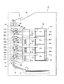
廃トナー容器40は、隔壁41により上下2つに仕切られた隔室42と43、及び隔室42と43に隣接して配置された1つの検知室44から構成され、隔室42には搬送ダクト35が接続される開口部45が形成され、隔室43には搬送ダクト36が接続される開口部46が形成されている。このほか、隔室42には上端部に検知室44に連通する通孔42aが、隔室43には上端部に検知室44に連通する通孔43aが形成されている。また、隔室42、43には、内部に収容された廃トナーの高さをならすならし部材42b、43bが設けてある。さらに、検知室44の底面付近には、廃トナーを検出するトナーセンサ47が取り付けられている。なお、廃トナー容器40は、画像形成装置10に着脱自在に取り付けられるものとする。
The
次に、その動作を説明する。各作像ユニット11Y〜11Kの感光体12Y〜12Kの表面にはそれぞれクリーニングブレード16Y2〜16K2が接触しており、感光体表面に形成された各色のトナー像が中間転写ベルト21に転写された後、表面に残留したトナーはクリーニングブレード16Y2〜16K2により掻き落され、本体16Y1〜16K1の内部に収容される。本体16Y1〜16K1の内部に収容された廃トナーは、搬送ダクト35を経て廃トナー容器40の開口部45から隔室42に収容される。
Next, the operation will be described. The cleaning blades 16Y2 to 16K2 are in contact with the surfaces of the
また、中間転写ベルト21に転写されたフルカラーのトナー像が記録紙Pに転写された後、表面に残留したトナーはクリーニングブレード25bにより掻き落され、本体25aの内部に収容される。本体25aの内部に収容された廃トナーは、搬送ダクト36を経て廃トナー容器40の開口部46から隔室43に収容される。
Further, after the full-color toner image transferred to the
隔室42、隔室43のいずれかで廃トナーが満杯になり、廃トナーがあふれると、あふれた廃トナーは通孔42aまたは通孔43aから検知室44に落下し、トナーセンサ47で検出される。検出信号は、図示しない画像形成装置の制御装置に入力され、これも図示しない操作パネル上に、廃トナー容器40が廃トナーで満杯であること、交換が必要であること等の趣旨のメッセージを表示するなどして交換を促す表示を行う。
When the waste toner becomes full in either the
以上説明した廃トナー容器では、隔壁により2つに仕切られた隔室のそれぞれに、検知室に連通する通孔が設けられているが、少なくとも1つの隔室に検知室に連通する通孔を設けてもよい。この場合、先に廃トナーがあふれると予想される隔室に通孔を設けるものとする。 In the waste toner container described above, a through hole communicating with the detection chamber is provided in each of the compartments divided into two by the partition wall, but at least one compartment has a through hole communicating with the detection chamber. It may be provided. In this case, it is assumed that a through hole is provided in a compartment where waste toner is expected to overflow first.
図3は、第2の実施の形態のタンデム方式のフルカラー画像形成装置の構成を説明する図、図4はその作像ユニット、クリーニング装置、及び廃トナー容器付近を拡大した説明図である。第1の実施の形態の画像形成装置との相違点は、4つの作像ユニットが垂直方向に配列され、各作像ユニットで形成されたトナー像が直接記録紙に重畳転写される構成であって、廃トナー容器も4つの隔室と1つの検知室から構成されている点にある。 FIG. 3 is a diagram for explaining the configuration of the tandem-type full-color image forming apparatus according to the second embodiment, and FIG. 4 is an explanatory diagram in which the image forming unit, the cleaning device, and the vicinity of the waste toner container are enlarged. The difference from the image forming apparatus of the first embodiment is that four image forming units are arranged in the vertical direction, and a toner image formed by each image forming unit is directly transferred onto a recording sheet. The waste toner container is also composed of four compartments and one detection chamber.
図3及び図4を参照して画像形成装置50の構成の概略を説明する。イエロー(Y)、マゼンタ(M)、シアン(C)、黒(K)の4色の作像ユニット51Y、51M、51C、51Kが垂直方向に配列され、各作像ユニット51Y〜51Kに沿って搬送ベルト61が配置されている。各作像ユニット51Y〜51Kには、それぞれ感光体52Y、52M、52C、52Kと、その周辺に帯電装置53Y、53M、53C、53K、露光装置54Y、54M、54C、54K、現像装置55Y、55M、55C、55K、及びクリーニング装置56Y、56M、56C、56Kが配置されている。感光体52Y〜52Kは矢印a方向に一定速度で回転するように構成されている。
An outline of the configuration of the image forming apparatus 50 will be described with reference to FIGS. 3 and 4. Yellow (Y), magenta (M), cyan (C), and black (K) four-color
搬送ベルト61は、駆動ローラ62と従動ローラ63との間に架設され、図示しない駆動装置で駆動される駆動ローラ62の回転により、矢印b方向に一定速度で移動するように構成されている。感光体52Y、52M、52C、52Kに対向する位置には、搬送ベルト61を挟んで転写装置58Y、58M、58C、58Kが配置されている。
The
垂直方向に配列された4つの作像ユニットの下方には給紙装置70が配置され、最下部の作像ユニット51Yの感光体52Yと搬送ベルト61との間に形成されるニップ部に向けて記録紙Pが搬送されるように構成されている。また、記録紙Pの搬送方向下流側には定着装置68が配置され、その下流側には排紙部69が配置されている。
A
以上の構成の動作を簡単に説明する。まず、感光体52Y〜52Kが回転を開始し、帯電装置53Y〜53Kにより感光体52Y〜52Kの表面が均一に帯電される。図示しない原稿読取装置或いは図示しないパソコン等から出力された赤(R)、青(B)、緑(G)の3原色に色分解された画像信号に基づいて、これに対応するイエロー(Y)、マゼンタ(M)、シアン(C)、黒(K)の画像信号が作像ユニット51Y、51M、51C、51Kに順次出力される。一方、給紙装置70からは記録紙Pが作像ユニット51Yに向けて搬送され、タイミングローラ65で一旦停止する。
The operation of the above configuration will be briefly described. First, the
まず、作像ユニット51Yに出力された画像信号により露光装置54Yが作動して感光体52Yの上に画像潜像が形成され、現像装置55Yにより現像されてイエローのトナー像が形成される。感光体52Yの上のイエローのトナー像が転写装置58Yの配置されている第1転写位置に来るタイミングに合わせてタイミングローラ65が回転を開始して記録紙Pの搬送が開始され、イエローのトナー像は転写装置58Yの作用により記録紙P上に転写される。
First, the
イエローのトナー像が転写された記録紙Pが転写装置58Mの配置されている第2転写位置に来るタイミングに合わせて、作像ユニット51Mの感光体52Mの上に画像潜像が形成され、現像装置55Mによりマゼンタのトナー像が形成される。感光体52Mの上のマゼンタのトナー像は転写装置58Mに作用により、記録紙P上のイエローのトナー像に重畳して転写される。
An image latent image is formed on the
同様にして、作像ユニット51Cの感光体52Cの上に形成されたシアンのトナー像が、記録紙P上に重畳して転写されたイエロー及びマゼンタのトナー像の上に重畳して転写され、さらに、作像ユニット51Kの感光体52Kの上に形成された黒のトナー像が、記録紙P上に重畳して転写されたイエロー、マゼンタ、シアンのトナー像の上に重畳して転写され、記録紙Pの上には、イエロー、マゼンタ、シアン及び黒の4色のトナー像が重畳したフルカラーのトナー像が形成される。この後、記録紙P上のフルカラーのトナー像は定着装置68で定着処理され、排紙部69に排出される。
Similarly, a cyan toner image formed on the
感光体52Y〜52Kの表面に形成された各色のトナー像の記録紙Pへの転写が終了すると、感光体52Y〜52Kの表面はそれぞれ対応するクリーニング装置56Y〜56Kにより残留した廃トナーの清掃が行われ、廃トナーはクリーニング装置56Y〜56Kの内部に回収される。
When the transfer of the toner images of the respective colors formed on the surfaces of the
以上、第2の実施形態の画像形成装置の構成と動作の概略を説明したが、高品質の画像を形成するため各色の作像ユニット51Y〜51Kに備えられている感光体のトナーの付着量を適切に制御するため、帯電電圧、現像バイアス、露光量などの作像条件が最適値に設定されることは、第1の実施形態のものと全く同じである。
The outline of the configuration and operation of the image forming apparatus according to the second embodiment has been described above, but the toner adhesion amount of the photoconductor provided in each color
次に、図4を参照して、クリーニング装置56Y〜56K、廃トナー容器80、及びクリーニング装置に回収された廃トナーの処理について説明する。
Next, with reference to FIG. 4, the processing of the waste toner collected in the
クリーニング装置56Y〜56Kは、それぞれ本体56Y1、56M1、56C1、56K1、クリーニングブレード56Y2、56M2、56C2、56K2、排出孔56Y3、56M3、56C3、56K3を備えており、排出孔56Y3、56M3、56C3、56K3は、それぞれ内部に搬送スクリューが配置された搬送ダクト75a、75b、75c、75dに接続されている。
The
搬送ダクト75a、75b、75c、75dは、それぞれ作像ユニット51Y〜51Kの背後(図3、図4では紙面に向かって後側)に略水平に配置されており、搬送ダクト75a、75b、75c、75dの搬送方向端部は、それぞれ後述する廃トナー容器80の開口部82a、82b、82c、82dに接続されている。
The
廃トナー容器80は、隔壁80a、80b、80cにより上下4つに仕切られた隔室81a、81b、81c、81d、及び隔室81a〜81dに隣接して配置された1つの検知室81eから構成され、隔室81a、81b、81c、81dにはそれぞれ搬送ダクト75a、75b、75c、75dが接続される開口部82a、82b、82c、82dが形成されている。
The
このほか、隔室81a、81b、81c、81dには、それぞれ上端部に検知室81eに連通する通孔83a、83b、83c、83dが形成されている。また、隔室81a、81b、81c、81dには、内部に収容された廃トナーの高さをならすならし部材84a、84b、84c、84dが設けてある。さらに、検知室81eの底面付近には、廃トナーを検出するトナーセンサ85が取り付けられている。なお、廃トナー容器80は、画像形成装置50に着脱自在に取り付けられるものとする。
In addition, through
次に、その動作を説明する。各作像ユニット51Y〜51Kの感光体52Y〜52Kの表面にはそれぞれクリーニングブレード56Y2〜56K2が接触しており、感光体表面に形成された各色のトナー像が記録紙Pに転写された後、表面に残留したトナーはクリーニングブレード56Y2〜56K2により掻き落され、本体56Y1〜56K1の内部に収容される。本体56Y1〜56K1の内部に収容された廃トナーは、搬送ダクト75a〜75dを経て廃トナー容器の開口部82a〜82dから隔室81a〜81dに収容される。
Next, the operation will be described. The cleaning blades 56Y2 to 56K2 are in contact with the surfaces of the
隔室81a〜81dのいずれかで廃トナーが満杯となりあふれると、あふれた廃トナーは通孔83a、83b、83c、83dのいずれかから検知室81eに落下し、トナーセンサ85で検出される。検出信号は、図示しない画像形成装置の制御装置に入力され、これも図示しない操作パネル上に、廃トナー容器80が廃トナーで満杯であること、交換が必要であること等の趣旨のメッセージを表示するなどして交換を促す表示を行う。
When waste toner is full and overflows in any of the
以上説明した廃トナー容器では、隔壁により4つに仕切られた隔室のそれぞれに、検知室に連通する通孔が設けられているが、少なくとも1つの隔室に検知室に連通する通孔を設けてもよい。この場合、先に廃トナーがあふれると予想される隔室(例えば黒の廃トナーが収容される隔室)に通孔を設けるものとする。 In the waste toner container described above, a through hole communicating with the detection chamber is provided in each of the four compartments divided by the partition wall, but at least one compartment has a through hole communicating with the detection chamber. It may be provided. In this case, a through hole is provided in a compartment (for example, a compartment in which black waste toner is accommodated) where waste toner is expected to overflow first.
画像形成処理に使用されずに感光体或いは中間転写ベルト上に残留した廃トナーを回収する廃トナー容器、及びその廃トナー容器を備えた画像形成装置である。廃トナー容器は上端に開口部を備えた複数の隔室と、開口部からあふれた廃トナーを収容する単一の検知室を備え、検知室内部に廃トナー検知装置を備えたので、隔室のいずれかが廃トナーで一杯になると検知され、スペース効率の高い廃トナー容器を提供できる。 A waste toner container that collects waste toner remaining on a photoreceptor or an intermediate transfer belt without being used for image formation processing, and an image forming apparatus including the waste toner container. Since the waste toner container includes a plurality of compartments having an opening at the upper end and a single detection chamber for containing waste toner overflowing from the opening, and the waste toner detection device is provided in the detection chamber, the compartment Any of the above is detected when the toner becomes full, and a waste toner container with high space efficiency can be provided.
10 画像形成装置
11Y、11M、11C、11K 作像ユニット
12Y、12M、12C、12K 感光体
13Y、13M、13C、13K 帯電装置
14Y、14M、14C、14K 露光装置
15Y、15M、15C、15K 現像装置
16Y、16M、16C、16K 第1クリーニング装置
16Y1〜16K1 本体
16Y2〜16K2 クリーニングブレード
16Y3〜16K3 排出孔
18Y、18M、18C、18K 第1転写装置
21 中間転写ベルト
22 第2転写ローラ
23 駆動ローラ
24 圧接ローラ
25 第2クリーニング装置
25a 本体
25b クリーニングブレード
25c 排出孔
27 タイミングローラ
28 定着装置
29 排紙部
30 給紙装置
36 搬送ダクト
40 廃トナー容器
41 隔壁
42、43 隔室
42b、43b ならし部材
42a、43a 通孔
44 検知室
45 開口部
50 画像形成装置
51Y、51M、51C、51K 作像ユニット
52Y、52M、52C、52K 感光体
53Y、53M、53C、53K 帯電装置
54Y、54M、54C、54K 露光装置
55Y、55M、55C、55K 現像装置
56Y、56M、56C、56K クリーニング装置
56Y1、56M1、56C1、56K1 本体
56Y2、56M2、56C2、56K2 クリーニングブレード
56Y3、56M3、56C3、56K3 排出孔
58Y、58M、58C、58K 転写装置
61 搬送ベルト
62 駆動ローラ
63 従動ローラ
65 タイミングローラ
68 定着装置
69 排紙部
75a、75b、75c、75d 搬送ダクト
80 廃トナー容器
80a、80b、80c 隔壁
81a、81b、81c、81d 隔室
81e 検知室
82a、82b、82c、82d 開口部
83a、83b、83c、83d 通孔
84a、84b、84c、84d ならし部材
85 トナーセンサ
10
56Y3, 56M3, 56C3,
Claims (9)
前記廃トナー容器は、上端に開口部を備えた複数の隔室と、前記各隔室の上端開口部に連結されて開口部からあふれた廃トナーを収容する単一の検知室とから構成され、
前記各隔室はそれぞれ前記トナー搬送装置の端部に接続されると共に、前記検知室の底部には検知室内部の廃トナーを検知する廃トナー検知装置が配置されていること
を特徴とする廃トナー容器。 In a waste toner container connected to end portions of a plurality of toner transport devices that transport waste toner,
The waste toner container includes a plurality of compartments each having an opening at an upper end, and a single detection chamber connected to the upper end opening of each compartment to store waste toner overflowing from the opening. ,
Each of the compartments is connected to an end of the toner conveying device, and a waste toner detection device for detecting waste toner in the detection chamber is disposed at the bottom of the detection chamber. Toner container.
前記廃トナー容器は、上端に開口部を備えた少なくとも1つの隔室を含む複数の隔室と、前記上端開口部に連結されて開口部からあふれた廃トナーを収容する単一の検知室とから構成され、
前記各隔室は、それぞれ前記トナー搬送装置の端部に接続されると共に、前記検知室の底部には検知室内部の廃トナーを検知する廃トナー検知装置が配置されていること
を特徴とする廃トナー容器。 In a waste toner container connected to end portions of a plurality of toner transport devices that transport waste toner,
The waste toner container includes a plurality of compartments including at least one compartment having an opening at an upper end, and a single detection chamber connected to the upper end opening to accommodate waste toner overflowing from the opening. Consisting of
Each of the compartments is connected to an end of the toner conveying device, and a waste toner detection device for detecting waste toner in the detection chamber is disposed at the bottom of the detection chamber. Waste toner container.
を特徴とする請求項1または2記載の廃トナー容器。 3. The waste toner container according to claim 1, wherein the plurality of compartments are a plurality of compartments partitioned by a plurality of partition walls having different heights inside the waste toner container.
を特徴とする請求項1乃至3のいずれかに記載の廃トナー容器。 4. The waste toner container according to claim 1, wherein the compartment includes a leveling member for leveling the height of the waste toner that has been transported from the toner transport device and accumulated therein.
を特徴とする請求項1又は2に記載の廃トナー容器。 The waste toner container according to claim 1, wherein the toner conveying device includes a conveying screw that conveys toner therein.
感光体及び転写体上に残留した廃トナーを清掃するクリーニング装置と、
前記クリーニング装置に回収された廃トナーを廃トナー容器に搬送する複数のトナー搬送装置と
を備えた画像形成装置において、
前記廃トナー容器は、上端に開口部を備えた複数の隔室と、前記隔室の上端開口部に連結されて開口部からあふれた廃トナーを収容する単一の検知室とから構成され、前記各隔室はそれぞれ前記トナー搬送装置の端部に接続されると共に、前記検知室の底部には検知室内部の廃トナーを検知する廃トナー検知装置が配置されていること
を特徴とする画像形成装置。 An image forming apparatus that develops an image latent image formed on a photoreceptor with toner and transfers the formed toner image to a transfer body;
A cleaning device for cleaning waste toner remaining on the photosensitive member and the transfer member;
An image forming apparatus comprising: a plurality of toner conveying devices that convey waste toner collected by the cleaning device to a waste toner container;
The waste toner container is composed of a plurality of compartments having an opening at an upper end, and a single detection chamber connected to the upper end opening of the compartment and storing waste toner overflowing from the opening. Each of the compartments is connected to an end of the toner conveying device, and a waste toner detection device for detecting waste toner in the detection chamber is disposed at the bottom of the detection chamber. Forming equipment.
感光体及び転写体上に残留した廃トナーを清掃するクリーニング装置と、
前記クリーニング装置に回収された廃トナーを廃トナー容器に搬送する複数のトナー搬送装置と
を備えた画像形成装置において、
前記廃トナー容器は、上端に開口部を備えた少なくとも1つの隔室を含む複数の隔室と、前記隔室の上端開口部に連結されて開口部からあふれた廃トナーを収容する単一の検知室とから構成され、前記各隔室はそれぞれ前記トナー搬送装置の端部に接続されると共に、前記検知室の底部には検知室内部の廃トナーを検知する廃トナー検知装置が配置されていること
を特徴とする画像形成装置。 An image forming apparatus that develops an image latent image formed on a photoreceptor with toner and transfers the formed toner image to a transfer body;
A cleaning device for cleaning waste toner remaining on the photosensitive member and the transfer member;
An image forming apparatus comprising: a plurality of toner conveying devices that convey waste toner collected by the cleaning device to a waste toner container;
The waste toner container includes a plurality of compartments including at least one compartment having an opening at an upper end, and a single container that is connected to the upper end opening of the compartment and stores waste toner overflowing from the opening. Each of the compartments is connected to an end of the toner conveying device, and a waste toner detection device for detecting waste toner in the detection chamber is disposed at the bottom of the detection chamber. An image forming apparatus.
を特徴とする請求項6又は7に記載の画像形成装置。 The image forming apparatus according to claim 6, wherein the waste toner container is detachably attached to the image forming apparatus.
を特徴とする請求項6又は7に記載の画像形成装置。 When the waste toner detection device provided in the waste toner container detects the waste toner, a detection result indicating that the waste toner container is full is displayed on an operation panel of the image forming apparatus. The image forming apparatus according to claim 6 or 7.
Priority Applications (1)
| Application Number | Priority Date | Filing Date | Title |
|---|---|---|---|
| JP2004109543A JP2005292608A (en) | 2004-04-02 | 2004-04-02 | Waste toner container and image forming apparatus equipped with same |
Applications Claiming Priority (1)
| Application Number | Priority Date | Filing Date | Title |
|---|---|---|---|
| JP2004109543A JP2005292608A (en) | 2004-04-02 | 2004-04-02 | Waste toner container and image forming apparatus equipped with same |
Publications (1)
| Publication Number | Publication Date |
|---|---|
| JP2005292608A true JP2005292608A (en) | 2005-10-20 |
Family
ID=35325572
Family Applications (1)
| Application Number | Title | Priority Date | Filing Date |
|---|---|---|---|
| JP2004109543A Pending JP2005292608A (en) | 2004-04-02 | 2004-04-02 | Waste toner container and image forming apparatus equipped with same |
Country Status (1)
| Country | Link |
|---|---|
| JP (1) | JP2005292608A (en) |
Cited By (5)
| Publication number | Priority date | Publication date | Assignee | Title |
|---|---|---|---|---|
| JP2008281700A (en) * | 2007-05-09 | 2008-11-20 | Canon Inc | Image forming apparatus |
| JP2010072310A (en) * | 2008-09-18 | 2010-04-02 | Konica Minolta Business Technologies Inc | Waste powder recovery container, and image forming device provided therewith |
| JP2010152239A (en) * | 2008-12-26 | 2010-07-08 | Konica Minolta Business Technologies Inc | Waste powder recovery device and image forming apparatus with the same |
| US20130183050A1 (en) * | 2012-01-18 | 2013-07-18 | Samsung Electronics Co., Ltd | Waste container and electrophotographic image forming apparatus including the same |
| JP2021043293A (en) * | 2019-09-10 | 2021-03-18 | 株式会社リコー | Waste toner recovery device, and image forming apparatus |
-
2004
- 2004-04-02 JP JP2004109543A patent/JP2005292608A/en active Pending
Cited By (9)
| Publication number | Priority date | Publication date | Assignee | Title |
|---|---|---|---|---|
| JP2008281700A (en) * | 2007-05-09 | 2008-11-20 | Canon Inc | Image forming apparatus |
| JP2010072310A (en) * | 2008-09-18 | 2010-04-02 | Konica Minolta Business Technologies Inc | Waste powder recovery container, and image forming device provided therewith |
| JP2010152239A (en) * | 2008-12-26 | 2010-07-08 | Konica Minolta Business Technologies Inc | Waste powder recovery device and image forming apparatus with the same |
| US20130183050A1 (en) * | 2012-01-18 | 2013-07-18 | Samsung Electronics Co., Ltd | Waste container and electrophotographic image forming apparatus including the same |
| KR20130084899A (en) * | 2012-01-18 | 2013-07-26 | 삼성전자주식회사 | Waste container and electrophotographic image forming apparatus using the same |
| US9069321B2 (en) * | 2012-01-18 | 2015-06-30 | Samsung Electronics Co., Ltd. | Waste container and electrophotographic image forming apparatus including the same |
| KR101872359B1 (en) * | 2012-01-18 | 2018-08-02 | 에이치피프린팅코리아 주식회사 | Waste container and electrophotographic image forming apparatus using the same |
| JP2021043293A (en) * | 2019-09-10 | 2021-03-18 | 株式会社リコー | Waste toner recovery device, and image forming apparatus |
| JP7284937B2 (en) | 2019-09-10 | 2023-06-01 | 株式会社リコー | Waste toner recovery device and image forming device |
Similar Documents
| Publication | Publication Date | Title |
|---|---|---|
| US7366457B2 (en) | Color image forming apparatus having toner recycling | |
| US9494907B2 (en) | Waste toner storing container, and image forming apparatus including waste toner storing container | |
| US7395022B2 (en) | Image forming apparatus with toner recovery system | |
| JP2007219426A (en) | Waste toner collecting apparatus and image forming apparatus | |
| JP2008197595A (en) | Toner container and image forming apparatus suitable for the same | |
| US20180011421A1 (en) | Image forming apparatus | |
| JP5245336B2 (en) | Developing device, image forming apparatus, and image forming method | |
| JP4380706B2 (en) | Image forming apparatus | |
| JP5070679B2 (en) | Image forming apparatus | |
| JP2005292608A (en) | Waste toner container and image forming apparatus equipped with same | |
| JP4952706B2 (en) | Image forming apparatus and toner supply method | |
| JP6183015B2 (en) | Image forming apparatus | |
| JP2008051933A (en) | Waste toner storage box and image forming apparatus | |
| JP2010107978A (en) | Image forming apparatus and developer filling method thereof | |
| JP4573059B2 (en) | Image forming apparatus | |
| JP2015059975A (en) | Image formation device | |
| US20070280740A1 (en) | Development device, process cartridge, and image forming apparatus | |
| JP6687882B2 (en) | Developing device and image forming apparatus | |
| JP2008065229A (en) | Toner storing component and image forming apparatus | |
| JP7135875B2 (en) | Image forming apparatus, waste toner management method and waste toner management program | |
| JP2025148141A (en) | Image forming system, developer replacement method, and developer storage unit for cleaning | |
| JP2005091848A (en) | Powdery/granular substance recovery device | |
| JP6736995B2 (en) | Developing device and image forming apparatus | |
| JP6624866B2 (en) | Image forming apparatus and control method thereof | |
| JP2013195639A (en) | Color image forming apparatus |