JP2005292487A - Lens positioning method and lens suction jig mounting device used in lens suction jig mounting device - Google Patents
Lens positioning method and lens suction jig mounting device used in lens suction jig mounting device Download PDFInfo
- Publication number
- JP2005292487A JP2005292487A JP2004107763A JP2004107763A JP2005292487A JP 2005292487 A JP2005292487 A JP 2005292487A JP 2004107763 A JP2004107763 A JP 2004107763A JP 2004107763 A JP2004107763 A JP 2004107763A JP 2005292487 A JP2005292487 A JP 2005292487A
- Authority
- JP
- Japan
- Prior art keywords
- lens
- image
- index
- line segment
- suction jig
- Prior art date
- Legal status (The legal status is an assumption and is not a legal conclusion. Google has not performed a legal analysis and makes no representation as to the accuracy of the status listed.)
- Granted
Links
Images


Landscapes
- Eyeglasses (AREA)
- Grinding And Polishing Of Tertiary Curved Surfaces And Surfaces With Complex Shapes (AREA)
Abstract
【課題】 レンズ吸着治具装着装置において、画像処理によって指標を自動的に検出できない場合であっても、レンズ吸着治具の取付位置を適切に決定する。
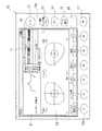
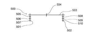
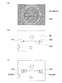
【解決手段】 液晶表示器11の表示面上に表示された位置決めカーソル500の縦線分501と横線分503との交点に隠しマーク441(第一指標)が一致するように左移動アイコン11a等を操作してレンズMLの像を平行移動させ、カーソル500の横線分503に水平線450(第二指標)が一致するように反時計回りアイコン11e等を操作して、レンズMLを回転させることにより、レンズ吸着治具120の装着位置となるカーソル500の中央縦線分504に、レンズMLのアイポイント位置を位置決めする。
【選択図】 図49
PROBLEM TO BE SOLVED: To appropriately determine a mounting position of a lens suction jig even in a case where an index cannot be automatically detected by image processing in a lens suction jig mounting apparatus.
A left movement icon 11a or the like such that a hidden mark 441 (first index) coincides with an intersection of a vertical line segment 501 and a horizontal line segment 503 of a positioning cursor 500 displayed on a display surface of a liquid crystal display 11. To move the image of the lens ML in parallel and rotate the lens ML by operating the counterclockwise icon 11e or the like so that the horizontal line 450 (second index) coincides with the horizontal line segment 503 of the cursor 500. Then, the eye point position of the lens ML is positioned at the center vertical line segment 504 of the cursor 500 which is the mounting position of the lens suction jig 120.
[Selection] FIG. 49
Description
本発明は、レンズ吸着治具装着装置に用いられるレンズの位置決め方法およびレンズ吸着治具装着装置に関し、詳細には、特に累進多焦点レンズにレンズ吸着治具を装着する際のレンズの位置決めの改良に関する。 The present invention relates to a lens positioning method and a lens suction jig mounting device used in a lens suction jig mounting device, and in particular, an improvement in lens positioning particularly when mounting a lens suction jig to a progressive multifocal lens. About.
従来より、未加工の眼鏡レンズは、所定の大きさの略球面切出し形状のものとして提供されており、この未加工の眼鏡レンズは、眼鏡フレームの枠形状に適合する形状となるように縁摺り加工される。 Conventionally, a raw spectacle lens is provided as a substantially spherical cut-out shape of a predetermined size, and this raw spectacle lens is trimmed so as to have a shape that matches the frame shape of the spectacle frame. Processed.
ここで、未加工の眼鏡レンズの縁摺り加工は、縁摺り加工装置によって行われるが、この縁摺り加工装置による加工は、レンズの加工中心を基準として行われるため、加工前にレンズの加工中心を予め求めておき、この加工中心にレンズ吸着カップ(レンズ吸着治具)を取り付けることが行われ、このレンズ吸着治具の装着は、レンズ吸着治具装着装置によって行われる。 Here, the edging processing of the unprocessed spectacle lens is performed by the edging processing apparatus. Since the processing by the edging processing apparatus is performed based on the processing center of the lens, the processing center of the lens before processing is performed. Is obtained in advance, and a lens suction cup (lens suction jig) is attached to the processing center, and the lens suction jig is mounted by a lens suction jig mounting device.
ところで、眼鏡レンズには、単焦点レンズ、バイフォーカルレンズ(多焦点レンズ)、累進多焦点レンズなどの種類があり、単焦点レンズの加工中心はレンズの光学中心であり、多焦点レンズや累進多焦点レンズの加工中心は、レンズのアイポイント位置である。 By the way, there are various types of spectacle lenses, such as a single focus lens, a bifocal lens (multifocal lens), and a progressive multifocal lens, and the processing center of the single focus lens is the optical center of the lens. The processing center of the focal lens is the eye point position of the lens.
単焦点レンズの光学中心は、レンズメータ等によって比較的容易に求めることができるが、多焦点レンズのアイポイント位置や累進多焦点レンズのアイポイント位置(EP値)は、未加工レンズに予め形成された適当な指標を基準として規定されている。 The optical center of a single focus lens can be determined relatively easily by a lens meter or the like, but the eye point position of a multifocal lens and the eye point position (EP value) of a progressive multifocal lens are formed in advance on an unprocessed lens. It is defined on the basis of the appropriate indicator.
例えば、多焦点レンズには近用の小玉が形成されているが、アイポイント位置はこの小玉の輪郭を基準として設定されている。一方、累進多焦点レンズには、多焦点レンズの如き小玉が形成されていないため、このままでは、ひと目で遠用部と近用部とを識別することができない。そこで、累進多焦点レンズには、遠用部と近用部との境界を示す線(第二指標)と遠用部を示す+等の記号が印刷によってレンズ表面に表示され、この線を基準としてアイポイント位置を探索することができる。 For example, a small lens for near use is formed on the multifocal lens, but the eye point position is set based on the contour of the small ball. On the other hand, since the progressive multifocal lens is not formed with small balls like the multifocal lens, the distance portion and the near portion cannot be distinguished at a glance. Therefore, in progressive multifocal lenses, a line indicating the boundary between the distance portion and the near portion (second index) and a symbol such as + indicating the distance portion are displayed on the lens surface by printing, and this line is used as a reference. As a result, the eye point position can be searched.
この印刷表示された第二指標は、未加工レンズが型等によって製造される工程で表示されているものではなく、形状が形成された後に付される。 The printed second indicator is not displayed in the process of manufacturing the unprocessed lens by a mold or the like, but is attached after the shape is formed.
すなわち、未加工の累進多焦点レンズの表面には、形状を形成する工程において、凹または凸の隠しマークと称される2個以上の指標(第一指標)が形成され、第二指標はこれら第一指標に基づいて、形状形成後に印刷される。 That is, on the surface of the raw progressive multifocal lens, in the process of forming the shape, two or more indicators (first indicators) called concave or convex hidden marks are formed. Based on the first index, it is printed after shape formation.
第一指標は、例えば、前述した遠用部と近用部との境界線を規定する2つのマークからなるが、このマークの他に、遠用部と近用部との屈折力差等を示す数字などの文字や記号等がさらに付加されている場合もある。 The first index is composed of, for example, two marks that define the boundary line between the distance portion and the near portion described above. In addition to this mark, the refractive power difference between the distance portion and the near portion, etc. There may be a case where characters such as numbers or symbols or the like are further added.
なお、付加的に形成される文字等は、右眼用レンズと左眼用レンズとで配置を異ならせることにより、左右識別用に用いられることもある。もちろん、文字等が付加的に設けられないものであっても、2つのマーク自体を互いに異なるものとすることにより、左右を容易に識別可能とすることもできる。 Note that additionally formed characters and the like may be used for left and right identification by changing the arrangement of the right eye lens and the left eye lens. Of course, even if a character or the like is not additionally provided, the left and right can be easily identified by making the two marks themselves different from each other.
そして、従来のレンズ吸着治具装着装置は、上述した第一指標および第二指標とが形成された眼鏡レンズを、位置調整可能の載置台に保持させ、撮像手段によってこの眼鏡レンズを撮像し、得られた眼鏡レンズの像を表示手段に表示するとともに、撮像して得られた眼鏡レンズの像に画像処理を施して、上記第一指標や第二指標を検出し、得られた第一指標や第二指標に基づいて、レンズ吸着カップの装着位置(加工位置)を求め、得られた装着位置にレンズ吸着カップを吸着させている(特許文献1,2)。
ところで、第二指標は印刷表示されているだけであるため、取扱い中にレンズ表面に不用意に触れたりすることにより、部分的に消えてしまうことがあり、一方、第一指標はレンズ表面に刻設または突設されているため、レンズの縁摺り加工後も残るものの、眼鏡レンズとしての性能に影響を及ぼしたり、眼鏡装用者に不快な違和感を与える虞がないように、第一指標の陥凹深さや突出高さは、極めて小さく設定されており、これらの指標の一部あるいは全部を画像処理によって適切に検出できない場合がある。 By the way, since the second index is only printed and displayed, it may disappear partially by touching the lens surface inadvertently during handling, while the first index is on the lens surface. Since it is engraved or protruded, it remains after the edge of the lens, but it does not affect the performance as a spectacle lens or cause an uncomfortable feeling to the spectacle wearer. The recess depth and the protrusion height are set to be extremely small, and some or all of these indices may not be properly detected by image processing.
そして、画像処理によって指標を適切に検出できないときは、レンズ吸着カップの取付位置を適切に設定することができない。 When the index cannot be detected properly by image processing, the attachment position of the lens suction cup cannot be set appropriately.
本発明は上記事情に鑑みなされたものであり、画像処理によって指標を自動的に検出できない場合であっても、レンズ吸着治具の取付位置を適切に決定することができるレンズ吸着治具装着装置に用いられるレンズの位置決め方法およびレンズ吸着治具装着装置を提供することを目的とする。 The present invention has been made in view of the above circumstances, and a lens suction jig mounting device capable of appropriately determining the mounting position of the lens suction jig even when the index cannot be automatically detected by image processing. It is an object of the present invention to provide a lens positioning method and a lens suction jig mounting device used for the above-mentioned.
本発明に係るレンズの位置決め方法およびレンズ吸着治具装着装置は、表示手段に、眼鏡レンズの指標を位置合わせするための所定のカーソルを表示させ、表示手段の表示面上で、カーソルとレンズの指標とが重畳するように、試行錯誤的に載置台を位置調整することにより、画像処理によって指標を自動的に認識処理できなかった場合にも、操作者が表示面上に表示された指標の像とカーソルとを肉眼で観察しながら、指標とカーソルとを位置合わせすることができ、これによって、指標と特定の幾何学的位置関係にあるレンズ吸着治具の取付位置に、眼鏡レンズを位置決めするものである。 In the lens positioning method and the lens suction jig mounting device according to the present invention, the display unit displays a predetermined cursor for aligning the index of the spectacle lens, and the cursor and the lens are arranged on the display surface of the display unit. By adjusting the position of the mounting table by trial and error so that it overlaps with the index, even if the index cannot be automatically recognized and processed by image processing, the operator displays the index displayed on the display surface. While observing the image and the cursor with the naked eye, the index and the cursor can be aligned, thereby positioning the spectacle lens at the mounting position of the lens suction jig that has a specific geometric positional relationship with the index. To do.
すなわち、本発明の請求項1に係るレンズの位置決め方法は、表面に所定の間隔を以て刻設または突設された複数個の第一指標と前記第一指標に基づいて印刷表示された第二指標とが形成された眼鏡レンズを保持する位置調整可能の載置台と、前記載置台を前記位置調整可能の範囲で変位させる位置調整手段と、前記載置台により保持された前記眼鏡レンズを撮像する撮像手段と、前記撮像手段によって撮像された前記眼鏡レンズの像に基づいて、前記指標を検出する画像処理手段と、画像を表示する表示手段と、前記撮像手段によって撮像された前記眼鏡レンズの像および前記画像処理して得られた前記指標の像を前記表示手段に表示させるように制御する表示制御手段と、前記眼鏡レンズの所定部位にレンズ吸着治具を装着する治具装着手段とを備えたレンズ吸着治具装着装置に用いられるレンズの位置決め方法であって、前記表示手段に、前記所定の間隔と同一間隔を以て縦方向に延びた複数の縦線分と前記複数の縦線分の全てに直交して横方向に延びた横線分とが一体化した位置決めカーソルを、前記眼鏡レンズの像に重畳して表示させるとともに、前記表示手段に表示された前記眼鏡レンズの像における前記指標の像のうち少なくとも2以上の像と、前記位置決めカーソルの所定部分とが対応するように、前記位置調整手段により前記載置台を位置調整することを特徴とする。
In other words, the lens positioning method according to
なお、カーソルは、表示手段の表示面内で平行移動させたり、回転させることができるようにしてもよい。 The cursor may be translated or rotated within the display surface of the display means.
また、本発明の請求項2に係るレンズの位置決め方法は、請求項1に係る位置決め方法において、前記表示手段に表示された前記眼鏡レンズの像における前記第一指標の2つ以上の像のそれぞれが、前記位置決めカーソルの前記縦線分に重畳されるように、前記載置台を位置調整することを特徴とする。 A lens positioning method according to a second aspect of the present invention is the positioning method according to the first aspect, wherein each of the two or more images of the first index in the image of the eyeglass lens displayed on the display means. However, the position of the mounting table is adjusted so as to be superimposed on the vertical line segment of the positioning cursor.
本発明の請求項3に係るレンズの位置決め方法は、請求項1に係る位置決め方法において、前記表示手段に表示された前記眼鏡レンズの像における前記第一指標の1つの像が前記位置決めカーソルのいずれかの前記縦線分に重畳されるように、かつ前記第二指標の像が前記位置決めカーソルの所定部分に重畳されるように、前記載置台を位置調整することを特徴とする。 The lens positioning method according to a third aspect of the present invention is the positioning method according to the first aspect, wherein one image of the first index in the image of the spectacle lens displayed on the display means is one of the positioning cursors. The position of the mounting table is adjusted so as to be superimposed on the vertical line segment and so that the image of the second index is superimposed on a predetermined portion of the positioning cursor.
また、本発明の請求項4に係るレンズの位置決め方法は、請求項2または3に係る位置決め方法において、前記カーソルは、2本の前記縦線分と1本の前記横線分とに加えて、前記横線分に直交し、かつ該横線分のうち前記2本の縦線分で両端を区切られた部分の中点を通る中央縦線分と、前記2本の縦線分に直交し、かつ等間隔の複数の補助横線分とを有し、前記第一指標が、前記縦線分と前記横線分との交点に、または前記縦線分といずれかの前記補助横線分との交点に、重畳されるように、前記載置台を位置調整することを特徴とする。
The lens positioning method according to
本発明の請求項5に係るレンズ吸着治具装着装置は、表面に所定の間隔を以て刻設または突設された複数個の第一指標と前記第一指標に基づいて印刷表示された第二指標とが形成された眼鏡レンズを保持する位置調整可能の載置台と、前記載置台を前記位置調整可能の範囲で変位させる位置調整手段と、前記載置台により保持された前記眼鏡レンズを撮像する撮像手段と、前記撮像手段によって撮像された前記眼鏡レンズの像に基づいて、前記指標を検出する画像処理手段と、画像を表示する表示手段と、前記撮像手段によって撮像された前記眼鏡レンズの像および前記画像処理して得られた前記指標の像を、前記表示手段に表示させるように制御する表示制御手段と、前記眼鏡レンズの所定部位にレンズ吸着治具を装着する治具装着手段とを備えたレンズ吸着治具装着装置であって、前記表示制御手段は、前記所定の間隔と同一間隔を以て縦方向に延びた複数の縦線分と前記複数の縦線分の全てに直交して横方向に延びた横線分とが一体化した位置決めカーソルを、前記眼鏡レンズの像に重畳して、前記表示手段に表示させるように制御することを特徴とする。 According to a fifth aspect of the present invention, there is provided a lens suction jig mounting device comprising: a plurality of first indicators that are engraved or protruded at a predetermined interval on a surface; and a second indicator that is printed and displayed based on the first indicators. A position-adjustable mounting table that holds the spectacle lens formed thereon, position adjusting means for displacing the mounting table within the position-adjustable range, and imaging for capturing the spectacle lens held by the mounting table And an image processing means for detecting the index based on an image of the spectacle lens imaged by the imaging means, a display means for displaying an image, an image of the spectacle lens imaged by the imaging means, and Display control means for controlling the display means to display an image of the index obtained by the image processing; jig mounting means for mounting a lens suction jig on a predetermined part of the spectacle lens; The lens suction jig mounting device is provided, wherein the display control means is arranged to be orthogonal to all of the plurality of vertical line segments extending in the vertical direction at the same interval as the predetermined interval and the plurality of vertical line segments. A positioning cursor integrated with a horizontal line segment extending in the direction is controlled to be superimposed on the image of the spectacle lens and displayed on the display means.
また、本発明の請求項6に係るレンズ吸着治具装着装置は、請求項5に係る装着装置において、前記カーソルは、2本の前記縦線分と1本の前記横線分とに加えて、前記横線分に直交し、かつ該横線分のうち前記2本の縦線分で両端を区切られた部分の中点を通る中央縦線分と、前記2本の縦線分に直交し、かつ等間隔の複数の補助横線分とを有することを特徴とする。
Moreover, the lens suction jig mounting device according to
本発明に係るレンズ吸着治具装着装置に用いられるレンズ位置決め方法によれば、表示手段に、眼鏡レンズに形成された複数の第一指標の間隔と同一間隔を以て縦方向に延びた複数の縦線分とこれら複数の縦線分の全てに直交して横方向に延びた横線分とが一体化した位置決めカーソルが、眼鏡レンズの像に重畳して表示され、この表示手段に表示された眼鏡レンズの像における指標の像のうち少なくとも2以上の像と、位置決めカーソルの所定部分とが対応するように、位置調整手段により載置台を位置調整することにより、位置決めカーソルの所定部分と指標の像とを対応させることができる。 According to the lens positioning method used in the lens suction jig mounting device according to the present invention, the display means includes a plurality of vertical lines extending in the vertical direction at the same interval as the intervals of the plurality of first indexes formed on the spectacle lens. A positioning cursor in which a horizontal line segment extending in the horizontal direction perpendicular to all of the plurality of vertical line segments is superimposed on the image of the spectacle lens and displayed on the display means. By adjusting the position of the mounting table by the position adjusting means so that at least two of the index images in the image correspond to the predetermined portion of the positioning cursor, the predetermined portion of the positioning cursor and the index image Can be made to correspond.
そして、カーソルの特定位置またはカーソルと幾何学的位置関係にある部分の位置と、治具装着手段がレンズ吸着治具を装着するレンズ吸着治具装着装置内における位置とは対応しているため、位置決めカーソルの所定部分と指標の像とが対応することによって、眼鏡レンズの指標と治具装着手段がレンズ吸着治具を装着する位置とは書的の幾何学的位置関係を以て対応し、レンズ吸着治具を眼鏡レンズの特定の位置すなわちアイポイント位置に装着させることができる。 And, because the position of the cursor or the position of the part that is in a geometric positional relationship with the cursor corresponds to the position in the lens suction jig mounting device where the jig mounting means mounts the lens suction jig, Since the predetermined portion of the positioning cursor corresponds to the index image, the index of the spectacle lens and the position where the jig mounting means mounts the lens suction jig correspond with a written geometric positional relationship, and the lens suction The jig can be attached to a specific position of the spectacle lens, that is, the eye point position.
また、上述した位置決めは、表示手段に表示された眼鏡レンズの像とカーソルとを目視して行うものであるため、画像処理によって自動的に全ての指標を検出することができない場合であっても、眼鏡レンズを適切に位置決めすることができる。 Further, since the positioning described above is performed by visually observing the image of the spectacle lens displayed on the display means and the cursor, even if all the indexes cannot be automatically detected by image processing. The eyeglass lens can be properly positioned.
また、本発明の請求項2に係るレンズの位置決め方法によれば、表示手段の表示面上において2つ以上の第一指標の像が視認可能なものであるときは、これら視認可能の2つの第一指標の像とカーソルとを対応させる(カーソルの縦線と横線との交点にそれぞれ第一指標を一致させる等)ことにより、カーソルと第一指標の像との位置関係、すなわちレンズ吸着治具装着装置のレンズ吸着治具によるレンズ吸着治具の装着位置と眼鏡レンズのアイポイント位置とを一致させることができる。しかも、第一指標は、眼鏡レンズの光学性能を規定する基準位置を示すものであるため、この第一指標にのみ基づいて眼鏡レンズの位置決めをすることにより、信頼性が高く高精度の位置決めを行うことができる。 According to the lens positioning method of the second aspect of the present invention, when two or more images of the first index are visible on the display surface of the display means, these two visible By associating the image of the first index with the cursor (for example, matching the first index to the intersection of the vertical and horizontal lines of the cursor, etc.), the positional relationship between the cursor and the image of the first index, that is, lens adsorption treatment. The mounting position of the lens suction jig by the lens suction jig of the tool mounting apparatus can be matched with the eye point position of the spectacle lens. In addition, since the first index indicates a reference position that defines the optical performance of the spectacle lens, positioning the spectacle lens based only on the first index enables highly reliable and accurate positioning. It can be carried out.
また、本発明の請求項3に係るレンズの位置決め方法によれば、表示手段の表示面上において第一指標の像は1つしか視認できない場合であっても、他に第二指標の像が視認可能であるときは、その視認可能の1つの第一指標の像と第二指標の像とを、それぞれカーソルの所定部分と対応させる(カーソルの縦線と横線との交点に第一指標を一致させ、カーソルの横線に第二指標を一致させる等)ことにより、カーソルと第一指標の像および第二指標の像との位置関係、すなわちレンズ吸着治具装着装置のレンズ吸着治具によるレンズ吸着治具の装着位置と眼鏡レンズのアイポイント位置とを一致させることができる。 Further, according to the lens positioning method of the third aspect of the present invention, even when only one first index image is visible on the display surface of the display means, there is another second index image. When it is visually recognizable, the image of the first index and the image of the second index that can be visually recognized are associated with predetermined portions of the cursor respectively (the first index is set at the intersection of the vertical and horizontal lines of the cursor). And the second index coincides with the horizontal line of the cursor), for example, the positional relationship between the cursor and the first index image and the second index image, that is, the lens by the lens suction jig of the lens suction jig mounting device. The mounting position of the suction jig and the eye point position of the spectacle lens can be matched.
また、本発明の請求項4に係るレンズの位置決め方法によれば、カーソルの中央縦線分上に、レンズ吸着治具の装着位置が設定されており、一方、2つの第一指標が設けられている眼鏡レンズでは、両第一指標を結んだ線に直交する線であって、2つの第一指標間の中点を通る線上に、アイポイント位置が設定されている。 According to the lens positioning method of the present invention, the mounting position of the lens suction jig is set on the center vertical line segment of the cursor, while two first indicators are provided. In the spectacle lens, the eye point position is set on a line that is orthogonal to the line connecting both the first indexes and passes through the midpoint between the two first indexes.
したがって、カーソルの、横線分と2つの縦線分とがそれぞれ交わる2つの交点に、第一指標の2つの像を一致させることにより、レンズ吸着治具の装着位置に、眼鏡レンズのアイポイント位置を容易に位置決めすることができる。 Therefore, by matching the two images of the first index at the two intersections where the horizontal line segment and the two vertical line segments respectively intersect, the eye point position of the spectacle lens is set at the mounting position of the lens suction jig. Can be easily positioned.
また、アイポイント位置は、2つの第一指標を結んだ線から、例えば2mm,4mm,6mmだけ離れた位置に存在していることがあり、横線からの距離が例えば2mm,4mm,6mmとなる位置に上記補助横線分が設けられ、この補助横線分と縦線分との交点に、第一指標を一致させる等対応させれば、中央縦線分と横線分との交点位置に対応する位置を、アイポイント位置として特定することができる。 Further, the eye point position may exist at a position separated by 2 mm, 4 mm, 6 mm, for example, from the line connecting the two first indexes, and the distance from the horizontal line is, for example, 2 mm, 4 mm, 6 mm. The position corresponding to the intersection position of the central vertical line segment and the horizontal line segment if the auxiliary horizontal line segment is provided at the position and the first index is made to correspond to the intersection of the auxiliary horizontal line segment and the vertical line segment. Can be specified as the eye point position.
本発明の請求項5に係るレンズ吸着治具装着装置によれば、表示手段に、眼鏡レンズに形成された複数の第一指標の間隔と同一間隔を以て縦方向に延びた複数の縦線分とこれら複数の縦線分の全てに直交して横方向に延びた横線分とが一体化した位置決めカーソルが、眼鏡レンズの像に重畳して表示され、この表示手段に表示された眼鏡レンズの像における指標の像のうち少なくとも2以上の像と、位置決めカーソルの所定部分とが対応するように、位置調整手段により載置台を位置調整することにより、位置決めカーソルの所定部分と指標の像とを対応させることができる。
According to the lens suction jig mounting device according to
そして、カーソルの特定位置またはカーソルと幾何学的位置関係にある部分の位置と、治具装着手段がレンズ吸着治具を装着するレンズ吸着治具装着装置内における位置とは対応しているため、位置決めカーソルの所定部分と指標の像とが対応することによって、眼鏡レンズの指標と治具装着手段がレンズ吸着治具を装着する位置とは書的の幾何学的位置関係を以て対応し、レンズ吸着治具を眼鏡レンズの特定の位置すなわちアイポイント位置に装着させることができる。 And, because the position of the cursor or the position of the part that is in a geometric positional relationship with the cursor corresponds to the position in the lens suction jig mounting device where the jig mounting means mounts the lens suction jig, Since the predetermined portion of the positioning cursor corresponds to the index image, the index of the spectacle lens and the position where the jig mounting means mounts the lens suction jig correspond with a written geometric positional relationship, and the lens suction The jig can be attached to a specific position of the spectacle lens, that is, the eye point position.
ここで、上述した位置決めは、表示手段に表示された眼鏡レンズの像とカーソルとを目視して行うものであるため、画像処理によって自動的に全ての指標を検出することができない場合であっても、眼鏡レンズを適切に位置決めすることができる。 Here, since the positioning described above is performed by visually observing the eyeglass lens image and the cursor displayed on the display means, all the indexes cannot be automatically detected by image processing. Also, the spectacle lens can be properly positioned.
また、本発明の請求項6に係るレンズ吸着治具装着装置によれば、カーソルの中央縦線分上に、レンズ吸着治具の装着位置が設定されており、一方、2つの第一指標が設けられている眼鏡レンズでは、両第一指標を結んだ線に直交する線であって、2つの第一指標間の中点を通る線上に、アイポイント位置が設定されている。
In the lens suction jig mounting device according to
したがって、カーソルの、横線分と2つの縦線分とがそれぞれ交わる2つの交点に、第一指標の2つの像を一致させることにより、レンズ吸着治具の装着位置に、眼鏡レンズのアイポイント位置を容易に位置決めすることができる。 Therefore, by matching the two images of the first index at the two intersections where the horizontal line segment and the two vertical line segments respectively intersect, the eye point position of the spectacle lens is set at the mounting position of the lens suction jig. Can be easily positioned.
また、アイポイント位置は、2つの第一指標を結んだ線から、例えば2mm,4mm,6mmだけ離れた位置に存在していることがあり、横線からの距離が例えば2mm,4mm,6mmとなる位置に上記補助横線分が設けられ、この補助横線分と縦線分との交点に、第一指標を一致させる等対応させれば、中央縦線分と横線分との交点位置に対応する位置を、アイポイント位置として特定することができる。 Further, the eye point position may exist at a position separated by 2 mm, 4 mm, 6 mm, for example, from the line connecting the two first indexes, and the distance from the horizontal line is, for example, 2 mm, 4 mm, 6 mm. The position corresponding to the intersection position of the central vertical line segment and the horizontal line segment if the auxiliary horizontal line segment is provided at the position and the first index is made to correspond to the intersection of the auxiliary horizontal line segment and the vertical line segment. Can be specified as the eye point position.
以下、本発明に係るレンズ吸着治具装着装置およびこの装置に用いられるレンズの位置決め方法についての具体的な実施の形態を、図面に用いて説明する。 Hereinafter, specific embodiments of a lens suction jig mounting device according to the present invention and a lens positioning method used in the device will be described with reference to the drawings.
まず、本実施形態のレンズ吸着治具装着装置1によって、レンズ吸着治具120が取り付けられる眼鏡レンズMLの詳細について説明する。
First, details of the spectacle lens ML to which the
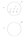
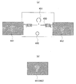
まず、この眼鏡レンズMLは、縁摺り加工前の未加工レンズであり、その種類としては、単焦点レンズ、バイフォーカルレンズ、累進多焦点レンズがある。そして、単焦点レンズMLには、図38(a)に示すように、複数個の印点410が印刷によって表示されたものと、同図(b)に示すように、印点410が付されていないものがある。
First, the spectacle lens ML is an unprocessed lens before bordering, and types thereof include a single focus lens, a bifocal lens, and a progressive multifocal lens. The single focus lens ML has a plurality of mark points 410 displayed by printing as shown in FIG. 38A, and a
ここで、印点410は、レンズ吸着治具120を取り付けるレンズMLにおける位置(アイポイント位置)Pの基準となる指標であり、後述する画像処理手段である演算制御回路130によって画像処理されて検出される。
Here, the
なお、印点410の無い単焦点レンズMLは、後述するCL測定装置300によって、屈折特性である球面度数S、円柱度数C、円柱軸の軸角度Aおよび光学中心OC等が測定されて、アイポイント位置Pが求められる。
The single focus lens ML without the
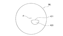
バイフォーカルレンズMLは、図39に示すように、略半円形状のいわゆる小玉420を有し、演算制御回路130は、この小玉420の輪郭421を画像処理して検出するとともに、検出された小玉420の輪郭421に基づいて、レンズ吸着治具120を取り付けるレンズMLにおける位置(アイポイント位置)Pを検出する。
As shown in FIG. 39, the bifocal lens ML has a so-called
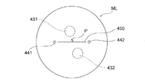
累進多焦点レンズMLは、遠用部431と近用部432とを有するとともに、遠用部431から近用部432まで連続的に焦点距離が変化するように形成されており、そのレンズ表面には、図40に示すように、遠用部431と近用部432との境界を示す水平線450(第二指標)と、この水平線450を挟んで遠用部431側を示す+記号が、印刷によってレンズ表面に表示されている。
The progressive multifocal lens ML has a
また、累進多焦点レンズMLは、同図に示すように、2つの隠しマーク441,442(第一指標)が刻設されている。この隠しマーク441,442は、前述した水平線450を規定するマークであるが、このマークの他に、遠用部431と近用部432との屈折力差等を示す数字などの文字や記号等がさらに付加されている場合もある。
The progressive multifocal lens ML is engraved with two
なお、付加的に形成される文字等は、右眼用レンズと左眼用レンズとで配置を異ならせることにより、レンズMLの左右識別用に用いられることもある。 Note that additionally formed characters and the like may be used for left and right identification of the lens ML by differently arranging the right eye lens and the left eye lens.
そして、演算制御回路130は、これら水平線450や2つの隠しマーク441,442を画像処理して検出するとともに、検出された水平線450や2つの隠しマーク441,442に基づいて、累進多焦点レンズMLにおける、アイポイント位置Pを検出する。
[構成]
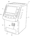
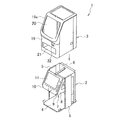
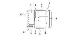
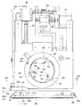
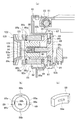
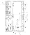
図1は、レンズ吸着治具120を眼鏡レンズに装着するための本発明の一実施形態に係るレンズ吸着治具装着装置1の外観を示したものである。
The
[Constitution]
FIG. 1 shows an appearance of a lens suction
このレンズ吸着治具装着装置1は、図8に示したフレーム2と、このフレーム2を覆う外ケース3を有する。
The lens suction
フレーム2は、底板4と、底板4の左右側縁の前後方向中央部に一体に設けられた側板5,5と、底板4の後縁部に一体に設けられた後壁6を有する。4aは、底板4上に固定されたベース板である。
The
また、底板4の前側上方には前側に突出するブラケット7が配設されている。このブラケット7は、図9に示したように後縁部が側板5,5に取り付けられた三角形状の側板部8,8と、側板部8,8の前縁部間を連設する連設板部9を有する。
In addition, a
この連設板部9は、上端に向かうにしたがって後方に向かうように傾斜させられている。また、この連設板部9には、操作パネル10および液晶表示器(表示手段)11が取り付けられている。
<操作パネル10>
この操作パネル10には、図2に示すように、液晶表示器11の右側に配置された操作パネル部10aと、液晶表示器11の下側に配置された操作パネル部10bを有する。
(操作パネル部10a)
この操作パネル部10aには、測定を中止する『ストップ』スイッチ12と、レイアウトデータの入力方式を切り替える『入力切替/メニュー』スイッチ13と、メモリに記憶されているフレームデータを呼び出す『メモリー』スイッチ14と、フレームデータを要求する『データ要求』スイッチ15と、入力設定用の『−+』スイッチ16と、カーソル移動用の『▽』スイッチ17とを有する。
The
<
As shown in FIG. 2, the
(
The
『入力切替/メニュー』スイッチ13は、所定時間(数秒、例えば2秒)以上押し続けることで、メニュー画面を表示させることができるようになっている。
The “input changeover / menu”
また、『入力切替/メニュー』スイッチ13は、ブロック指示(吸着指示)待ちであって、測定後の停止状態において押されると、マニュアル位置合わせや位置設定後の確定を指示するのに用いることができるようになっている。
Further, the “input switch / menu”
『メモリー』スイッチ14は、隠しマーク観察モードのときに押されると、液晶表示器11の画面を隠しマーク記憶画面に切り替えるようになっている。
When the “memory”
『データ要求』スイッチ15は、レンズ吸着治具装着装置1に接続されるフレーム形状測定装置(図示せず)から玉型形状データ(θi,ρi)の転送を要求するために用いられる。
The “data request”
『−+』スイッチ16は、液晶表示器11に表示され、かつ表示色が『▽』スイッチ17により反転表示されている部分の数値データの増減設定に用いられる。また、『−+』スイッチ16は、マニュアル位置合わせのときに、液晶表示器11の表示倍率の切替えを行うためにも用いられる。
The “− +”
『▽』スイッチ17は、液晶表示器11に表示されるデータ入力部のカーソル移動に用いられる。ここでいうカーソルは、液晶表示器11に表示される複数のデータ入力枠(データ入力部)の部分のうち、いずれか1つの表示色が反転させられたり、あるいは他の色に変化させられて、データ入力が可能な状態となっている状態をいう。
(操作パネル部10b)
この操作パネル部10bには、液晶表示器11の下縁に沿って配列されたファンクションキーF1〜F6が設けられている。また、操作パネル部10bには、眼鏡レンズの右眼用・左眼用の加工の指定や表示の切替え等を行う『左』スイッチ18L、『右』スイッチ18Rが設けられている。
<ファンクションキーF1〜F6>
ファンクションキーF1〜F6は、眼鏡レンズMLの加工に関する設定時に使用される他、加工工程で液晶表示器11に表示されたメッセージに対する応答・選択用として用いられる。
The “▽”
(
The
<Function keys F1 to F6>
The function keys F1 to F6 are used at the time of setting related to the processing of the spectacle lens ML, and are also used for response / selection to a message displayed on the
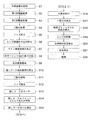
加工に関する設定時(レイアウト画面)においては、ファンクションキーF1はレンズ種類入力用(店舗用エリア)および累進レンズメーカ指定用として用いられ、ファンクションキーF2はレンズ素材入力用として用いられ、ファンクションキーF3はフレーム種類入力用として用いられ、ファンクションキーF4は面取り加工種類入力用として用いられ、ファンクションキーF5は鏡面加工入力用として用いられ、ファンクションキーF6はコース(モード)選択用として用いられる。
・ファンクションキーF1
このファンクションキーF1で入力されるレンズ種類としては、図3に示したように、『単焦点』、『印点』、『累進』、『バイフォーカル』、『隠しマーク』、『自動判別』等がある。また、このファンクションキーF1で入力される累進レンズメーカとしては、メーカM1,M2,M3,・・・・・等がある。
・ファンクションキーF2
ファンクションキーF2で入力されるレンズ素材としては、図3に示したように、『プラ』、『高プラ』、『ガラス』、『アクリル』、『調光ガラス』等がある。ここで、『プラ』はプラスチックを意味する。
・ファンクションキーF3
このファンクションキーF3で入力される眼鏡フレームFの種類しては、図3に示したように、『メタル』、『セル』、『オプチル』、『平』、『溝掘り(細)』、『溝掘り(中)』、『溝掘り(太)』等がある。
At the time of processing setting (layout screen), function key F1 is used for lens type input (store area) and progressive lens manufacturer designation, function key F2 is used for lens material input, and function key F3 is The function key F4 is used for inputting a chamfering type, the function key F5 is used for inputting a mirror finish, and the function key F6 is used for selecting a course (mode).
・ Function key F1
As shown in FIG. 3, the lens type input with the function key F1 is “single focus”, “marking point”, “progressive”, “bifocal”, “hidden mark”, “automatic discrimination”, etc. There is. In addition, there are manufacturers M1, M2, M3,... As the progressive lens manufacturers input with the function key F1.
・ Function key F2
As shown in FIG. 3, the lens material input by the function key F2 includes “plastic”, “high plastic”, “glass”, “acryl”, “light control glass”, and the like. Here, “Pura” means plastic.
・ Function key F3
As shown in FIG. 3, the types of the spectacle frame F input with the function key F3 include “metal”, “cell”, “optil”, “flat”, “groove (thin)”, “ There are "groove digging (middle)" and "groove digging (thick)".
なお、『ポイント:前金具』、『ポイント:後金具』、『ポイント:複合金具』等も含めることもできる。
・ファンクションキーF4
ファンクションキーF4で入力される面取り加工種類としては、図3に示したように、『なし』、『小(前後)』、『中(前後)』、『大(前後)』、『特殊(前後)』、『小(後)』、『中(後)』、『大(後)』、『特殊(後)』等がある。
・ファンクションキーF5
ファンクションキーF5で入力される鏡面加工としては、図3に示したように、『なし』、『あり』、『面取部鏡面』等がある。
・ファンクションキーF6
ファンクションキーF6で入力される加工コースとしては、図3に示したように、オート』、『試し』、『モニター』、『枠替え』、『内トレース』等がある。
<レイアウト画面>
また、レイアウト画面としては、例えば図4に示したような眼鏡レンズにレンズ吸着治具を吸着するためのレイアウト画面を表示させる『レイアウト・吸着』のモードや、例えば図5に示したような玉型形状情報(θi,ρi)に隠された眼鏡レンズにレンズ吸着治具を吸着させたときの状態を示す『レイアウト』のモードがある。
“Point: front bracket”, “point: rear bracket”, “point: composite bracket”, etc. can also be included.
・ Function key F4
As shown in Fig. 3, the types of chamfering input with the function key F4 are "None", "Small (front / rear)", "Medium (front / rear)", "Large (front / rear)", "Special (front / rear) ) ”,“ Small (after) ”,“ middle (after) ”,“ large (after) ”,“ special (after) ”, etc.
・ Function key F5
As shown in FIG. 3, there are “None”, “Available”, “Chamfered portion mirror surface”, and the like as the mirror finish input by the function key F5.
・ Function key F6
As shown in FIG. 3, machining courses input with the function key F6 include “auto”, “trial”, “monitor”, “frame change”, “internal trace”, and the like.
<Layout screen>
Further, as the layout screen, for example, a “layout / suction” mode for displaying a layout screen for sucking a lens suction jig onto a spectacle lens as shown in FIG. 4 or a ball as shown in FIG. There is a “layout” mode that indicates a state when the lens suction jig is attracted to the spectacle lens hidden in the mold shape information (θi, ρi).
そして、『レイアウト』タブTB1を選択した状態のときには、メッセージ表示エリアE1、数値表示エリアE2、および状態表示エリアE3にそれぞれ区画された状態で表示される。 When the “layout” tab TB1 is selected, the message display area E1, the numerical value display area E2, and the state display area E3 are displayed.
また、外ケース3は、図1および図8に示したように、前壁19を有する。この前壁19の上部には、後方に傾斜する傾斜壁部19aが形成され、傾斜壁部19aには液晶用開口20が形成されている。そして、この液晶用開口20には、図1に示したように液晶表示器11および操作パネル10が配設されている。さらに、前壁19の下部にはテーブル出没用開口21が形成され、前壁19の上下方向中間部の右よりの部分には吸着盤取付用開口22が形成されている。
Moreover, the outer case 3 has the
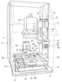
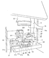
また、図6(a)に示したようにフレーム2内には、全体検出光学系100、隠しマーク検出光学系200、および屈折特性測定用のCL測定装置300が配設されている。
<全体検出光学系100>
この全体検出光学系100は、照明光学系101と全体観察光学系102とを有する。
Further, as shown in FIG. 6A, the entire detection
<Whole detection
The entire detection
照明光学系101は、赤外発光LED等の光源103,ピンホール板104,コリメータレンズ105,回転反射板106等の光学部材をこの順に有する。この回転反射板106は、駆動モータ107の回転軸107aに取り付けられていて、駆動モータ107により回転駆動されるようになっている。
The illumination
この駆動モータ107は、回転軸107aの軸O1が照明光学系101の光軸O2に対して傾斜させられている。これにより、鉛直方向に向けられた軸O1に対して回転反射板106の面の向きは所定角度αだけ僅かに傾斜させられている。この所定角度αとしては数度(例えば2°〜4°、好ましくは3°)である。
In the
また、回転反射板106は、図6(b)に示したように、金属板または樹脂板等からなる回転円板106aと、回転円板106aの上面に貼り付けられた反射シート106bとを有する。この反射シート106bは、非常に微小なコーナキューブ108を全面に多数縦横に配列して樹脂で一体に形成したものである。
Further, as shown in FIG. 6B, the
このような構成とすることにより、コーナキューブ108に入射した入射光束109は、コーナキューブ108内で反射した後、コーナキューブ108から出射して入射光束109に沿って戻る出射光束110となる。なお、このような光学特性を有する反射板は、再帰性反射板等と称されている。
With such a configuration, the
一方、反射シート106bの表面で反射した正反射光束111は、入射光束109に対してある角度を以って反射するため、出射光束110のように入射光束109に沿って戻ることはなく、全体観察や隠しマーク検出に悪影響が生じない(ノイズ光とならない)。
On the other hand, the specularly reflected
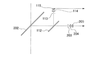
また、全体観察光学系102は、コリメータレンズ105、ハーフミラー112、絞り板113、結像レンズ114およびCCD(二次元受光素子、エリアセンサ)115等の光学部材をこの順に有する。
<隠しマーク検出光学系200>
この隠しマーク検出光学系200は、上述した照明光学系101と隠しマーク観察光学系201とを有する。
The overall observation
<Hidden mark detection
The hidden mark detection
また、隠しマーク観察光学系201は、コリメータレンズ105、ハーフミラー202、絞り板203および結像レンズ204等の光学部材と、撮像手段であるCCD205とが、この順に配置されたものである。
The hidden mark observation
このような全体検出光学系100と隠しマーク検出光学系200とのうち、回転反射板107以外の光学部材等は、図10に示した光学部材収納ケース23内に収納されている。この光学部材収納ケース23は、図示を省略したブラケットでフレーム2に固定されている。
(全体観察光学系の他の配置例)
なお、全体観察光学系102は、図7に示すように構成することもできる。すなわち、図6のハーフミラー112を、ハーフミラー202と絞り板203との間に配設し、ハーフミラー202で反射した反射光束をハーフミラー112で反射させて、この反射した光束を、絞り板113および結像レンズ114を介して、CCD115に導くようにしてもよい。
<CL測定装置300>
このCL測定装置300は、フレーム2の奥側(後壁6側)に位置して、ベース板4a上に固定されているとともに、図12に示したブラケット301を有する。このブラケット301は、上部筐体302と下部筐体303とを有し、上部筐体302には、図6に示した測定光束投影系304が配設され、下部筐体303内には、図6に示した受光光学系305が配設されている。306は下部筐体303上に固定された円錐筒状のレンズ受けである。
Of the entire detection
(Other arrangement examples of the entire observation optical system)
The overall observation
<
The
測定光束投影系304は、光源307、ピンホール板308、反射ミラー309およびコリメータレンズ310等の光学部材が、この順に配置されたものである。また、受光光学系305は、パターン板311および結像レンズ312等の光学部材と、CCD313とが、この順に配置されたものである。
<リッド取付構造>
ベース板4aの前端部(前壁19側端部)上には、図15,16に示したL字状のブラケット24が固定されている。このブラケット24の起立板部24aには開口25が形成され、起立板部24aの側部にはフランジ24b,24bが一体に形成されている。
In the measurement light
<Lid mounting structure>
An L-shaped
開口25はリッド26で閉成されている。このリッド26の内面の一側下端部側には、図14,15に示したヒンジ用のブラケット27が固定されている。このブラケット27は、図15に示したように、後下方に向けて円弧状に湾曲する湾曲部27aと、湾曲部27a後部か端からリッド26側に直線状に延びる直線板部27bと、直線板部27bに対して直角(垂直)に下方に向けて連設されたストッパ板部27cとを有する。
The
一方、起立板部24aの内面の両側部近傍には、図14に示すように、開口25より下方に位置させた軸受部材28,28が一体的に設けられている。
On the other hand, as shown in FIG. 14, bearing
そして、ブラケット24は、直線板部27bとストッパ板部27cとの接続コーナ部27dが、支持軸29を介して軸受部材28,28に、回動自在に保持されている。また、ブラケット27は、支持軸29に捲回され、かつブラケット27と起立板部24aとの間に介装された撚りコイルバネ30によって、図15において反時計回り方向に回動付勢されている。
In the
これにより、リッド26は、起立板部24aの前面に当接して開口25を閉成している。また、この状態ではリッド26が、外ケース3のテーブル出没用開口21を閉成している。
<レンズ挟持解除用アーム>
また、ベース板4aの一側部上には、図13に示したようにリッド26に近接させてレンズ挟持解除に用いるアーム31が固定されている。このアーム31は、図11,14に示したように、起立部31aと、起立部31aの上端からリッド26に沿って延びる水平部31bと、水平部31bの先端からリッド26側に延びる板部31cと、板部31cの先端から下方に延びる係止爪部31dとを有する。
<レンズ保持手段移動機構>
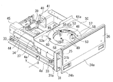
また、ベース板4a上には、レンズ保持手段移動機構32が配設されている。このレンズ保持機構32は、図13,15,16に示したように、ベース板4a上の後端部およびアーム31近傍に位置させた横ガイドレール(X方向ガイドレール)33と、横ガイドレール33上に配設された横移動部材(X方向移動部材)34と、横移動部材34を横ガイドレール33上に横方向(X方向)に移動自在に支持しているベアリング35とを有する。また、横移動部材34に、上述した駆動モータ107が取り付けられている。
As a result, the
<Lens clamp release arm>
Further, on one side of the
<Lens holding means moving mechanism>
A lens holding means moving
また、レンズ保持手段移動機構32は、図17に示したように横移動部材34の両側部上に前後(図17の紙面と垂直な方向;Y方向)に向けてそれぞれ固定した前後ガイドレール36と、ガイドレール36上に配設された板状の前後移動部材(前後移動ステージ、Y方向移動部材)37と、前後移動部材37をガイドレール36に前後移動自在に指示しているベアリング38とを有する。この横移動部材34に上述した駆動モータ107が取り付けられている。
Further, as shown in FIG. 17, the lens holding means moving
また、横移動部材34には、図13に示したように、ナット部材39が固定され、ナット部材39には、軸線を横方向に向けた横送りネジ(X送りネジ)40が螺着されている。この横送りネジ40は、ベース板4a上に固定されたパルスモータ(X駆動モータ)41で回転駆動させられるようになっている。
Further, as shown in FIG. 13, a
一方、前後移動部材37には、駆動モータ107に取り付けられた回転反射板106に対向して、円形の光透過孔42が形成されている。
On the other hand, a circular
さらに、前後移動部材37には、図15に示したように、ブラケット37aおよび固定ネジ37bを介してナット部材43が固定され、ナット部材43には、軸線を前後方向に向けた前後送りネジ(Y送りネジ)44が螺着されている。この前後送りネジ44は、横移動部材34上に固定されたパルスモータ(Y駆動モータ)45で回転駆動させられるようになっている。
<レンズ保持手段>
前後移動部材37の光透過孔42上には、図13〜17に示したように、レンズホルダ(レンズ保持手段)46が配設されている。
Further, as shown in FIG. 15, a
<Lens holding means>
As shown in FIGS. 13 to 17, a lens holder (lens holding means) 46 is disposed on the
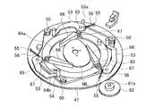
このレンズホルダ46は、図16に示すように、内周面の下部に支持フランジ47aが設けられたリング状ギヤ47を有する。このリング状ギヤ47は、周面に周方向に延びるギヤ部47bおよび環状溝47cを有する。
As shown in FIG. 16, the
そして、この環状溝47cには、図18(b)に示したように、前後移動部材37上に回転自在に取り付けられた複数のローラ37Rが係合している。この複数のローラ37Rは、光透過孔42に沿って配設されていて、リング状ギヤ47を前後移動部材37に回転自在に保持している。
As shown in FIG. 18B, the
また、レンズホルダ46は、リング状ギヤ47内に嵌合され、かつ支持フランジ47a上に着脱可能に支持されたレンズ支持用の透明円板48と、透明円板48上に120°間隔で突設された軸状レンズ受49とを有する。なお、透明円板48は、ガラスまたはプラスチック等であってもよい。
The
リング状ギヤ47上には、図18(a)に示したように、周方向に等ピッチ(60°間隔)で配設された6つの小ギヤ50が回転自在に取り付けられ、この6つの小ギヤ50には、タイミングベルト51が掛け渡されている。このタイミングベルト51の外周面には、リング状ギヤ47に回転自在に取り付けられたテンションローラ52が当接させられている。
On the ring-shaped
さらに、一つおきの小ギヤ50には、アーム53の一端部(基端部)がそれぞれ固定され、各アーム53の他端部(先端部)上には上下に延びるレンズ保持軸(レンズ保持部材)54が取り付けられている。
Furthermore, one end portion (base end portion) of each
リング状ギヤ47上には、アーム53の一端部に近接させてバネ受けピン55が取り付けられ、このバネ受けピン55とアーム53の一端部との間には、コイルスプリング56が介装されている。このコイルスプリング56は、アーム53の先端部がリング状ギヤ47の中心側に回動するように、アーム53を回動付勢している。
On the ring-shaped
このような構成の小ギヤ50やアーム53の一端部は、図13,14に示したように、カバーリング57で覆われている。カバーリング57は、ビス58により、リング状ギヤ47に固定されている。
One end portions of the
また、カバーリング57の内周面には、レンズ保持軸54を係合させる係合切欠59が、周方向120°間隔で形成されている。さらに、カバーリング57の外周面には、切欠60が形成されている。
Further,
また、3つのアーム53の一つの一端部には、切欠60から上方に突出する係合突起53aが形成されている。
In addition, an
さらに、前後移動部材37には、パルスモータ等からなる取付角設定モータ61が固定され、この取付角設定モータ61の出力軸61aには、ギヤ62が取り付けられている。このギヤ62は、リング状ギヤ47のギヤ部47bに噛合させられている。したがって、取付角設定モータ61によりギヤ62を回転駆動することにより、リング状ギヤ47が回転させられることになる。
Further, a mounting
なお、前後移動部材37は、レンズホルダ46の部分を除いてステージカバーSCでカバーされている。
<枠替え用レンズホルダ>
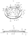
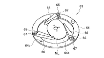
また、上述した軸状レンズ受49を有するレンズ支持用の透明円板48に代えて、図19に示した枠替えレンズホルダ63を、図20に示すように、リング状ギヤ47内に着脱可能に取り付けることもできる。
The forward / backward moving
<Frame changing lens holder>
Further, in place of the lens-supporting
この枠替えレンズホルダ63は、透明円板48の外径と同じ外径のリング状枠64と、リング状枠64内に固定された透明円板64aと、リング状枠64上に等ピッチ(120°間隔)で突設された3つ(複数)の支持軸65と、一端部(基端部)が支持軸65に回動自在に取り付けられたレンズ保持アーム(レンズ保持部材)66と、レンズ保持アーム66の他端部(先端部)をリング状枠64の中心側に回動付勢しているコイルバネ67とを有する。なお、レンズ保持アーム66は、先端に向かうにしたがって先細り形状に形成されている。
The frame
このようなリング状枠64は、上述した透明円板64aよりも肉厚に形成されていて、上述したアーム53のレンズ保持軸54を、図20に示すように、リング状ギヤ47上に対比させた状態で、リング状ギヤ47内に着脱自在に嵌合させられる。これにより、レンズ保持軸54は、リング状枠64の外周面に当たって、リング状枠64内に移動することはない。この際も、リング状枠64は図16のリング状ギヤ47のフランジ47a上に支持される。
Such a ring-shaped
なお、64bは、枠替え用のリング状枠64に設けられた透孔であって、枠替えレンズホルダ63の検出に用いられる。
<レンズ吸着機構>
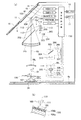
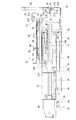
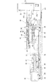
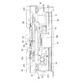
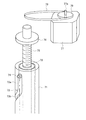
フレーム2の側板5には、図10,11に示したように、レンズ吸着機構68が装着されている。
In addition, 64b is a through-hole provided in the ring-shaped
<Lens adsorption mechanism>
A
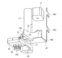
このレンズ吸着機構68は、図10,21,23,24に示したようなブラケット69を有する。このブラケット69は、上支持板部69aと、下支持板部69bと、支持板部69a,69bを連設している縦板部69cとにより、全体として略コ字状に形成されている。
The
また、縦板部69cの一側の上下部には、取付片69d,69dが一体的、かつ直角に設けられている。この取付片69d,69dを、図10,11のフレーム2に設けた側板5に、図示しないビスで取り付けることにより、ブラケット69は、縦板部69cを側板5に直角にした状態で取り付けられている。
Further, mounting
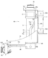
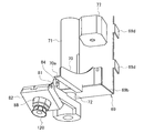
また、レンズ吸着機構68は、縦板部69cの正面の下部に前側に向けて取り付けられた固定アーム70と、上下支持板部69a,69bに上下端部を、図示しないビス等の固定手段で固定したカム筒71と、図22に示したカム筒71内に回転自在、かつ昇降自在(上下動自在)に嵌合された雌ねじ筒72とを有する。なお、雌ねじ筒72の下端部は、下支持板部69bを貫通して、下方に突出している。
The
また、カム筒71には、図10,21,22に示したように、上下に延びるカムスリット(ガイドスリット)73が形成されている。このカムスリット73は、図18に示した上縦スリット部73aと、この上縦スリット部73aの下端から螺旋状に90°捩れつつ、下方に向けて形成された螺旋状スリット部73bと、この螺旋状スリット部73bの下端からカム筒71の下部まで直線状に長く形成された下縦スリット部73cとを有する。
The
そして、雌ねじ筒72の外周面の上端部近傍には、図22に示したように、ガイドローラ74が回転自在に保持され、このガイドローラ74がカムスリット73内に配設されている。
A
また、雌ねじ筒72には、上支持板部69aを貫通して下支持板部69b側まで延びる雄ねじ軸(螺軸)75が回転自在に螺着されている。この雄ねじ軸75は、上支持板部69aに回転自在かつ軸線方向(上下方向)に移動不能に保持されている。
Further, a male screw shaft (screw shaft) 75 extending through the upper
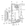
そして、雄ねじ軸75の上端部には、プーリ76が固定されている。また、上支持板部69aの下面には、駆動モータ77が取り付けられている。この駆動モータ77の出力軸77aは、上支持板部69aを貫通して上方に突出しており、この出力軸77aには、プーリ78が固定されている。プーリ76,78には、タイミングベルト79が掛け渡されている。
A
さらに、雄ねじ筒75の下端部には、水平に延びる可動アーム80が固定されている。この可動アーム80は、ガイドローラ74がカムスリット73の上縦スリット部74a内にあるときには、正面を向くようになっているとともに、ガイドローラ74がカムスリット73の下縦スリット部74c内にあるときには、横方向(X方向)で、かつ図6の左方を向くようになっている。
Further, a horizontally extending
この可動アーム80の先端部には、図21,23,24に示したように、可動アーム80の延びる方向と直交し、かつ水平に延びる支持軸81を介して、可動ブラケット(可動部材)82が回動自在に保持されている。
As shown in FIGS. 21, 23, and 24, a movable bracket (movable member) 82 is attached to a distal end portion of the
この可動ブラケット82と可動アーム80との間には、図25〜29に示すように、支持軸81に捲回した捩りコイルバネ83が介装されている。この捩りコイルバネ83は、可動ブラケット82を、図23に示すように、可動アーム80の先端部下面側に折り畳む方向に回動付勢している。
A
また、可動ブラケット82の基端部側面には、ローラ84が回転自在に保持されている。このローラ84は、可動アーム80が正面を向いた状態で上昇させられたときに、固定アーム70の下端に設けた水平板部(ストッパ板部)70aに当接して、可動ブラケット82を、捩りコイルバネ83のバネ力に抗して、図21に示すように、垂直な状態まで回動させるようになっている。
(吸着治具保持手段)
さらに、この可動ブラケット82には吸着治具保持手段85が装着されている。
Further, a
(Suction jig holding means)
Further, a suction jig holding means 85 is attached to the
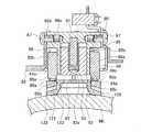
この吸着治具保持手段85は、図27(a),29に示したように、筒部86aがブラケット82の貫通孔82aに挿通されたホルダ本体86と、ホルダ本体86のフランジ86bを可動ブラケット82の対向片82b,82bに固定しているビス87,87とを有する。このホルダ本体86には、貫通孔82aから突出する筒部86aが設けられ、筒部86aの外周には、外筒88が長手方向に移動可能に嵌合されている。
As shown in FIGS. 27A and 29, the suction jig holding means 85 includes a holder
この外筒88には、180°間隔で図27(b),(c)に示したようなスリット88aが形成され、各スリット88aには、一端部がホルダ本体86に保持された線状バネ89,89の他端の折曲部89a,89aが配設されている。この折曲部89aには、周面の一部を図27(b),(c)に示したように、スリット88aから外筒88内に突出させた直線部89bが設けられている。
The
また、ホルダ本体86と外筒88との間には、コイルスプリング90が介装されていて、外筒88をホルダ本体86を、図27(a)の左方にバネ付勢している。このホルダ本体86の筒部86a内には、一端部が筒部86aの端壁86cに固定されたバネ支持軸91が、同心に配設されている。
Further, a
また、筒部86a内には、有底筒状のスライド筒体92が、軸線方向に移動自在に嵌合され、スライド筒体92内でバネ支持軸91が遊びを有する状態で挿入されている。
Further, a bottomed
このスライド筒体92内には、コイルスプリング93の一端部側が挿入されているとともに、摩擦保持されている。また、このコイルスプリング93内には、バネ支持軸91が挿入されていて、このコイルスプリング93の他端部は、バネ支持軸91の端壁86c側の端部に締まり嵌めにより保持されている。
One end of the
さらに、ホルダ本体86の筒部86aには、図28(a),(b)に示したように、下端に開放したスリット状に延びる切欠ガイド86d,86dが、180°間隔で形成されている。また、外筒88には、図27(b),28(c)に示したように、上端に開放したスリット状の切欠ガイド88bが形成されている。
Further, as shown in FIGS. 28A and 28B, the
この切欠ガイド86d,88bは、図27,28(d)に示したように、互いに一致させられている。そして、この切欠ガイド86d,88bには、スライド筒体92の外周面に、図26,27(a)に示したように取り付けられたガイド軸94が挿通されている。また、図30に示したように、スライド筒体92の端壁92aには、位置決ピン95が突設されている。なお、外筒88の外端部には、テーパ凹部88cが形成されている。
As shown in FIGS. 27 and 28 (d), the notch guides 86d and 88b are made to coincide with each other. And the
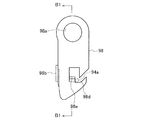
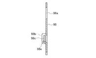
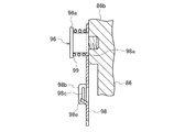
また、図30,36に示したように、ホルダ本体86のフランジ86bには、フック支持軸96が螺着固定されているとともに、バネ受けネジ97がフック支持軸96に隣接して螺着されている。96aはフック支持軸96のフランジである。
30 and 36, a
このフック支持軸96は、図36に示すように、板状の係止フック98の軸挿通孔98aに遊びを有する状態で挿通されて、係止フック98をフランジ86bに支持している。この係止フック98の一側部には、バネ係止突起98bが形成され、このバネ係止突起98にはスリット98cが形成されている。
As shown in FIG. 36, the
そして、フック支持軸96の外周に嵌合されたコイルバネ99の両端部が、バネ受けネジ97とスリット98c内に係止されている。このコイルバネ99は、係止フック98を、図30の反時計回り方向に回動付勢しているとともに、フランジ86b,96a間に介装されて、係止フック98をフランジ86bに軽い力で押し付けている。
Then, both end portions of the
この係止フック98には、図30〜32に示したように、係止切欠98dが形成されているとともに、係止切欠98dの回動付勢方向とは反対側の縁部に位置させて、傾斜ガイド片98eが形成されている。そして、係止切欠98d内には、スライド筒体92の外周面に取り付けたガイド軸94の先端の小径軸部94aが挿入されている。
As shown in FIGS. 30 to 32, the locking
図1に示したレンズ吸着治具120は、図26に示したように、取付軸部121と、この取付軸部121に一体に設けられたゴムや軟質の合成樹脂等の弾性部材とからなるカップ部122とを有する。そして、取付軸部121には、端面および周面に開放する位置決溝123が形成されている。この取付軸部121が外筒88内に嵌着されるようになっている。
<制御回路>
上述した液晶表示器11(表示手段)は、図6に示した演算制御回路130(表示制御手段、画像処理手段)により作動制御されるようになっている。
As shown in FIG. 26, the
<Control circuit>
The liquid crystal display 11 (display means) described above is controlled by the arithmetic control circuit 130 (display control means, image processing means) shown in FIG.
また、この演算制御回路130は、パルスモータ(X駆動モータ)41、パルスモータ(Y駆動モータ)45、取付角設定モータ61、光源103、駆動モータ107、および光源307を作動制御するようになっている。
The
さらに、操作パネル110からのスイッチ操作信号およびCCD115,205,313からの画像信号(測定信号)は、演算制御回路130に入力されるようになっている。
Further, a switch operation signal from the
また、画像処理手段としての演算制御回路130は、図38(a)に示した単焦点レンズMLについて検出された像に対して画像処理を施し、単焦点レンズMLのレンズ表面に印刷表示された印点410を検出して、レンズ吸着治具120を取り付けるレンズMLにおける位置(アイポイント位置)Pを求める処理や、図39に示したバイフォーカルレンズMLについて検出された像に対して画像処理を施し、バイフォーカルレンズMLが有する小玉420の輪郭421を検出して、アイポイント位置Pを求める処理や、図40に示した累進多焦点レンズMLについて検出された像に対して画像処理を施し、累進多焦点レンズMLに刻設された隠しマーク441,442を検出して、アイポイント位置Pを求める処理等を行う。
Further, the
ここで、演算制御回路130が行うこのようなアイポイント位置Pを求める処理は、予め設定された処理手順にしたがって自動的に行われ、さらに、求められたアイポイント位置Pがレンズ吸着治具120の装着位置となるように、レンズMLが自動的に移動されるようになっている。
Here, the processing for obtaining the eye point position P performed by the
ところで、特に累進多焦点レンズMLを、レンズ吸着治具120の吸着対象とした場合、アイポイント位置を探索する基準となる隠しマーク441,442は、上述した自動処理によって検出することができない場合もあり、隠しマーク441,442のうちいずれか1つしか検出することができなかった場合や、2つとも検出することができなかった場合は、アイポイント位置を検出することができず、レンズMLの移動も自動的に行うことができない。
By the way, in particular, when the progressive multifocal lens ML is an object to be attracted by the
そこで、本実施形態のレンズ吸着治具装着装置1の演算制御回路130は、手動でレンズMLの位置決めを行うための処理が備えられている。
Therefore, the
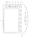
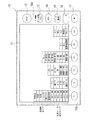
すなわち、表示制御手段としての演算制御回路130は、表示手段である液晶表示器11に、図41に示すように、レンズMLに形成された2つの隠しマーク441,442間の間隔(例えば、34mmに規定されている。)と同一間隔(=34mm)を以て縦方向に延びた2本の縦線分501,502と、両縦線分501,502に直交して横方向に延びた横線分503と、横線分503に直交し、かつ横線分503のうち2本の縦線分501,502で両端を区切られた部分の中点を通る中央縦線分504と、2本の縦線分501,502に各別に直交し、かつ等間隔(例えば、2mm間隔)で各縦線分501,502に配置された3本ずつの補助横線分505,506,507,508,509,510とが一体化した位置決めカーソル500を、図42に示すように、レンズMLの像ML′に重畳して表示させるように制御する。
That is, the
そして、上述した隠しマークの自動検出処理(図43のフローチャートに示す処理)によって、隠しマーク441,442のうち一方(例えば、隠しマーク441)のみが検出され、他方(例えば、隠しマーク442)が検出されなかった場合には、液晶表示器11の表示面上で、操作者が肉眼で、表示されたカーソル500と、検出された隠しマーク441および印刷表示の水平線450とを、位置合わせするように、レンズMLまたはカーソル500を移動させることにより、可動アーム80がレンズ吸着治具120を装着させる位置に、レンズMLのアイポイント位置を適切にセットすることができる。
Then, only one of the
一方、上述した隠しマークの自動検出処理によって、いずれの隠しマーク441,442も検出されなかったときは、液晶表示器11の表示面上で、操作者が肉眼で、いずれかの隠しマーク441または442を探索し、表示されたカーソル500と、探索して得られた隠しマーク441または442および印刷表示の水平線450とを、位置合わせするように、レンズMLまたはカーソル500を移動させることにより、可動アーム80がレンズ吸着治具120を装着させる位置に、レンズMLのアイポイント位置を適切にセットすることができる。
[作用]
次に、本実施形態のレンズ吸着治具装着装置1の作用を説明する。
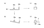
(1)レンズ吸着治具120のレンズ吸着機構68への取り付け
図1は、眼鏡レンズの隠しマークの検出や眼鏡レンズの屈折測定の前の状態を示している。
On the other hand, when any of the
[Action]
Next, the operation of the lens suction
(1) Attaching the
この状態では、図22に示したようにレンズ吸着機構68のガイドローラ74が、カム筒71に設けたカムスリット73の上縦スリット部73aの上端部内に位置していて、雌ねじ筒72が最も上昇した位置にある。
In this state, as shown in FIG. 22, the
この位置では、雌ねじ筒72の下端部に取り付けられた可動アーム80が、図10,21に示したように、最も上昇した位置に位置させられて、可動ブラケット82のローラ84が、図21に示したように、固定アーム70の水平板部70aに当接させられて、可動ブラケット80が、図25に示した捩りコイルバネ83のバネ力に抗して、図17に示したように下方に向けられた状態となる。
At this position, the
この状態では、可動ブラケット80が、図1に示したように、吸着盤取付用開口22に臨ませられた状態となっている。したがって、操作者は、吸着盤取付用開口22から、レンズ吸着治具120の取付軸部121を、図26,27に示したように可動ブラケット80に設けられた外筒88内に挿入する。この際、取付軸部121に設けられた位置決め溝123に位置決めピン95を挿入する。
In this state, as shown in FIG. 1, the
この取付軸部121の押込みに際して、スライド筒体92が、取付軸部121により、コイルスプリング93のバネ力に抗してホルダ本体86の端壁86c側に移動させられる。
When the mounting
この後、レンズ吸着治具120の取付軸部121をさらに、線状バネ89の直線部89bを乗り越えるように、外筒88内に押し込むと、取付軸部121が、線状バネ89の直線部89bを、線状バネ89の折曲部89aのバネ力に抗して外筒88のスリット88a内に押し込む状態となる。
Thereafter, when the mounting
この状態では、直線部89bが折曲部89aのバネ力により、図29に示すように、取付軸部121の外周面に圧接された状態となって、取付軸部121を外筒88内に保持した状態となるので、外筒88が下方を向いてもレンズ吸着治具120が下方に落下することはない。
In this state, the
この状態では、ガイド軸94の小径軸部94aが、係止フック98の係止切欠98d内に位置させられている。
(2)眼鏡レンズのレンズホルダ46への保持
(レンズホルダ46の外ケース3外への露出およびレンズ載置)
次に、操作パネル10のファンクションキーF1の操作により、図3の自動判別を選択して、図2の『左』スイッチ18Lまたは『右』スイッチ18Rのうちいずれかを選択すると、パルスモータ45が、演算制御回路130により作動制御されて、前後送りネジ44が正転させられ、ナット部材43および前後移動部材37がリッド26側に移動させられる。
In this state, the small-
(2) Holding the spectacle lens to the lens holder 46 (exposing the
Next, when the automatic discrimination in FIG. 3 is selected by operating the function key F1 on the
この移動に伴い、前後移動部材37を覆うステージカバーSCは、リッド26に当接した後、このリッド26を撚りコイルバネ30のバネ力に抗して、支持軸29を中心に、図15の時計回り方向に回動させて開き、開口25,21から外ケース3外に出て、前後移動部材37に装着したレンズホルダ46を露出させる。
With this movement, the stage cover SC that covers the forward / backward moving
この際、レンズホルダ46の係合突起53aが、アーム31の係止爪部31dに係合させられて、図18(a)の係合突起53aと一体のアーム53が、コイルスプリング56のバネ力に抗して、小ギヤ50と一体的に、時計回り方向に回動させられ、係合突起53aと一体のアーム53のレンズ保持軸54が、図14のカバーリング57の切欠60側に移動する。
At this time, the engaging
これに伴い、図18(a)のタイミングベルト51が、時計回り方向に回転させられて、タイミングベルト52により、残りの他の2つの小ギヤ50も時計回り方向に回動させられて、この残りの2つの小ギヤ50と一体のアーム53が、コイルスプリング56のバネ力に抗して、時計回り方向に回動させられ、この残りの2つの小ギヤ50とアーム53のレンズ保持軸54とが、図14のカバーリング57の切欠60側に移動する。
Accordingly, the
このようにして、3つのレンズ保持軸54が、カバーリング57側に移動させられて開いた状態で、図18(b)に示したように、レンズホルダ46の軸状レンズ受49上に、眼鏡レンズMLを載置する。
(レンズホルダ46の外ケース3内への移動およびレンズ保持)
この後、演算制御回路130は、パルスモータ45を作動制御して、前後送りネジ44を逆転させ、ナット部材43および前後移動部材37を、外ケース3内に移動させる。
In this way, with the three
(Moving the
Thereafter, the
これに伴い、前後移動部材37を覆うステージカバーSCが、リッド26から離れると、このリッド26が、撚りコイルバネ30のバネ力により、支持軸29を中心として、図15の反時計回り方向に回動さられて閉じ、開口25,21がリッド26により閉成させられる。
Accordingly, when the stage cover SC that covers the
この際、レンズホルダ46の係合突起53aが、アーム31の係止爪部31dから離れると、図18(a)中、係合突起53aと一体のアーム53が、コイルスプリング56のバネ力により、小ギヤ50と一体に、反時計回り方向に回動させられ、係合突起53aと一体のアーム53のレンズ保持軸54が、図14のカバーリング57の中央側に移動する。
At this time, when the
これに伴い、図18(a)のタイミングベルト51が、反時計回り方向に回転させられて、タイミングベルト52により、残りの他の2つの小ギヤ50も反時計回り方向に回動させられて、この2つの小ギヤ50と一体のアーム53が、コイルスプリング56のバネ力により、反時計回り方向に回動させられ、この残りの2つの小ギヤ50と一体のアーム53のレンズ保持軸54が、図14のカバーリング57の中心側に移動する。
Accordingly, the
このようにして3つのレンズ保持軸54が、カバーリング57の中心側に移動させられて、レンズホルダ46の軸状レンズ受49上に載置された眼鏡レンズMLの周面に当接して、眼鏡レンズMLを図34に示すように、3つのレンズ保持軸54で挟持(保持)する。
(3)眼鏡レンズMLの有無の確認
このようにして演算制御回路130は、眼鏡レンズMLが3つのレンズ保持軸54で挟持(保持)された状態で、レンズホルダ46を、回転反射板106と、全体検出光学系100および隠しマーク検出光学系200の照明光学系101との間に移動させると、パルスモータ45の作動を停止させる。
In this way, the three
(3) Confirmation of Presence / absence of the Eyeglass Lens ML In this way, the
この後、演算制御回路130は、光源103を点灯させて、光源103から赤外光を出射させる一方、駆動モータ34を駆動制御して回転反射板106を回転させる。
Thereafter, the
この光源3からの赤外光は、ピンホール板104およびハーフミラー112,202を透過してコリメータレンズ105に入射し、コリメータレンズ105により平行光束とされた後、被検レンズである眼鏡レンズMLに照射される。
The infrared light from the light source 3 passes through the
この照射により、眼鏡レンズMLを透過した赤外光は、回転反射板106により反射させられて反射光となる。そして、反射光の一部は、眼鏡レンズMLおよびハーフミラー202を透過した後、ハーフミラー112で反射させられて、絞り板113および結像レンズ114を介して、CCD115に、眼鏡レンズMLの像や軸状レンズ受49の像を結像させる。
By this irradiation, the infrared light transmitted through the spectacle lens ML is reflected by the
眼鏡レンズMLに隠しマークやペイントマークがある場合には、これらの像もCCD115上に結像される。CCD115からの画像信号は、演算制御回路130に入力される。
If the spectacle lens ML has a hidden mark or a paint mark, these images are also formed on the
そして、演算制御回路130は、CCD115からの画像信号を受けると、液晶表示器11に、レンズMLの像を表示させる。
When the
この後、演算制御回路130は、レンズMLが、レンズホルダ46に実際に保持されているか否か(レンズMLの存否)の判定処理を行い、存在しているとの判定結果のときは、その存在しているレンズMLが、印点有りの単焦点レンズであるか、印点無しの単焦点レンズであるか、バイフォーカルレンズであるか、累進多焦点レンズであるか、というレンズMLの種別判定処理を行う。
Thereafter, the
そして、判定して得られたレンズMLの種別に応じて、アイポイント位置の検出処理およびレンズ吸着治具120の装着処理が、自動的に行われる。
Then, according to the type of the lens ML obtained by the determination, the eye point position detection process and the
なお、レンズMLの種別が印点無しの単焦点レンズの場合には、CL測定装置300による測定が行われて、アイポイント位置の検出処理およびレンズ吸着治具120の装着処理が、自動的に行われる。
When the lens ML is a single-focus lens with no mark, measurement is performed by the
以下、特に、累進多焦点レンズMLにおけるアイポイント位置の自動検出処理について説明する。
(4)累進多焦点レンズMLの像における隠しマーク441,442の像の自動検出処理
隠しマーク441,442の自動検出およびレンズ吸着治具120の装着(吸着)の自動処理は、図43のフローチャートに示す処理手順によって行われる。
Hereinafter, the automatic detection processing of the eye point position in the progressive multifocal lens ML will be described in particular.
(4) Automatic Detection Processing of
すなわち、まず、全体画像の取得処理(S1)を行う。このときは、レンズMLの全体を表示する画像を、例えば8bit(0〜255)のグレイスケールによる画像データとして取得する(図44(a))。 That is, first, an entire image acquisition process (S1) is performed. At this time, an image displaying the entire lens ML is acquired as, for example, image data of an 8-bit (0 to 255) gray scale (FIG. 44A).
次に、第1次閾値処理(S2)を施す。ステップ1(S1)で取得した画像データに対して、設定した輝度閾値以下となる画素の輝度値を0に変換する(図44(b))。 Next, primary threshold processing (S2) is performed. For the image data acquired in step 1 (S1), the luminance value of the pixel that is equal to or lower than the set luminance threshold value is converted to 0 (FIG. 44B).
次いで、第2次閾値処理(S3)および2値化処理(S4)を施す。ステップ2(S2)で作成した画像に対して、平滑化処理を施し、中間画像を作成する。そして、得られた中間画像とステップ2(S2)で作成した画像とで、対応する画素ごとに差分を算出し、設定された閾値以上の画素を、輝度値255に変換処理し、閾値以下の画素を、輝度値0に変換処理することにより、2値化画像を作成する(図44(c))。 Next, secondary threshold processing (S3) and binarization processing (S4) are performed. A smoothing process is performed on the image created in step 2 (S2) to create an intermediate image. Then, a difference is calculated for each corresponding pixel between the obtained intermediate image and the image created in step 2 (S2), and a pixel that is equal to or greater than the set threshold is converted into a luminance value 255, and the difference is equal to or smaller than the threshold. A binarized image is created by converting the pixels to a luminance value of 0 (FIG. 44 (c)).
なお、平滑化処理としては、例えば、注目画素の近傍8画素の輝度値の平均値を、当該注目画素の新たな輝度値として置き換える処理などを適用することができる。 As the smoothing process, for example, a process of replacing the average value of the luminance values of the eight neighboring pixels of the target pixel with the new luminance value of the target pixel can be applied.
次いで、ノイズ除去処理(S5)を施す。ここでは、膨張処理と収縮処理とを1回ずつ行い、画素の連結性を高め、その後、2値化された画像の微小なノイズを消去するために、画像全体に亘って、輝度値255の画素の連結数が5pixel以下のものを全て消去する。 Next, noise removal processing (S5) is performed. Here, in order to improve the connectivity of the pixels by performing expansion processing and contraction processing once, and then erase minute noise in the binarized image, the luminance value 255 over the entire image. Delete all connected pixels that are 5 pixels or less.
なお、膨張処理としては、例えば、注目画素の近傍8画素に輝度値255の画素が1つでもあれば、当該注目画素の輝度値を255に置換する処理等、収縮処理としては、例えば、注目画素の近傍8画素に輝度値0の画素が1つでもあれば、当該注目画素の輝度値を0に置換する処理等を、それぞれ適用することができる。 As the expansion process, for example, if there is at least one pixel having a luminance value of 255 in the 8 pixels near the target pixel, the contraction process such as a process for replacing the luminance value of the target pixel with 255 is, for example, If there is at least one pixel with a luminance value of 0 in the eight neighboring pixels, a process for replacing the luminance value of the target pixel with 0 can be applied.
次いで、レンズMLの仮の幾何中心の決定処理(S6)を行う。レンズMLの外形輪郭上の左下、右下および上の3点を選び、その3点を通る円の中心を求め、この中心の位置をレンズMLの仮の中心位置とする。これは、次の探索領域を決定するためのものであるため、厳密である必要はない。 Next, a provisional geometric center determination process (S6) of the lens ML is performed. The lower left, lower right and upper three points on the outer contour of the lens ML are selected, the center of a circle passing through the three points is obtained, and the position of this center is set as the temporary center position of the lens ML. This is for determining the next search area and need not be exact.
次いで、ライン抽出領域の決定処理(S7)を行う。レンズMLの仮中心位置の周囲の領域(300×60pixel)を、水平線450の抽出処理領域として設定する(図44(d))。 Next, a line extraction region determination process (S7) is performed. An area (300 × 60 pixels) around the provisional center position of the lens ML is set as an extraction processing area for the horizontal line 450 (FIG. 44D).
次に、水平ペイント抽出(傾き計算)処理(S8)を施す。ステップ(S7)で指定した領域内で、輝度値255の画素の数が最も多い直線を求めるハフ変換処理を施して、得られた直線を水平線450とする(図45(a))。ただし、抽出した直線であっても、輝度値255の画素の数が30pixel以下の場合は、検出しようとする水平線450ではないものとする。なお、ハフ変換処理は、水平線450の傾きも求める。
Next, horizontal paint extraction (tilt calculation) processing (S8) is performed. A Hough transform process for obtaining a straight line having the largest number of pixels having the luminance value 255 within the region designated in step (S7) is performed, and the obtained straight line is defined as a horizontal line 450 (FIG. 45 (a)). However, even in the case of the extracted straight line, if the number of pixels having the luminance value 255 is 30 pixels or less, it is not the
次に、拡大画像の取得処理(S9)を行う。ステップ8(S8)で取得された傾きに基づいて、レンズMLの回転を行う。そして、隠しマーク441,442を、液晶表示器11の表示面上で目視できるように、2倍拡大の画像を取得する(図45(b))。
Next, an enlarged image acquisition process (S9) is performed. Based on the inclination acquired in step 8 (S8), the lens ML is rotated. Then, a double-magnified image is acquired so that the
次いで、隠しマーク抽出領域の設定処理(S10)を施す。ステップ6(S6)において取得されたレンズMLの仮幾何中心位置から、水平方向17mm(17pixel)の地点付近に、隠しマーク441,442が存在すると推定し、これらの地点を中心とした縦60pixel×横100pixelからなる矩形領域を、隠しマーク441,442の探索処理の領域として設定する(図45(c))。
Next, a hidden mark extraction area setting process (S10) is performed. From the temporary geometrical center position of the lens ML acquired in step 6 (S6), it is estimated that
次に、2値化処理(S11)を施す。ステップ10(S10)により設定した領域に、高速版Cannyオペレータを施し、エッジの抽出処理を行う。これにより、輝度値が急激に変化する箇所について、輝度値が255に変換される(図46(a))。 Next, a binarization process (S11) is performed. The high-speed version of the Canny operator is applied to the area set in step 10 (S10) to perform edge extraction processing. As a result, the luminance value is converted to 255 at a location where the luminance value changes abruptly (FIG. 46A).
次いで、ノイズ除去処理(S12)を施す。ステップ12(S12)により作成された2値化画像から、(i)領域の外周に接している水平線450などのエッジを取り除き、(ii)ラベリングを行い、連結画素数が小さいエッジを取り除く(図46(b))。
Next, noise removal processing (S12) is performed. From the binarized image created in step 12 (S12), (i) an edge such as the
次いで、隠しマーク441,442の探索処理(S13)を施す。縦30pixel×横30pixelの枠を生成し、この枠内領域で最もエッジ量が多い場所を探す。
Next, a search process (S13) for the
次に、隠しマーク441,442または水平線450の判定処理(S14)を行い、隠しマーク441,442が存在する位置における何らかのペイント記号の有無を判定する。ステップ13(S13)の探索処理によって得られた隠しマーク441,442の枠内領域を対象として、レンズMLの最初の全体画像(S1)を、低い閾値(例えば、輝度値100程度)によって2値化処理する(図47(a))。
Next, determination processing (S14) of the
そして、この2値化処理後の画像において、何らかの模様が検出された場合には、ペイント記号が存在するものと判定し(図47(b))、このペイント記号を用いた処理に移行する。 If any pattern is detected in the binarized image, it is determined that a paint symbol is present (FIG. 47B), and the process proceeds to processing using the paint symbol.
次いで、隠しマーク441,442の中心検出処理(S15)を施す。ステップ13(S13)で設定された枠内領域のエッジに基づいて、隠しマーク441,442の重心位置を求める。この重心位置を、隠しマーク441,442の中心位置とする(図47(c))。
Next, the center detection process (S15) of the
次に、角度を求める(S16)。ステップ15(S15)により得られた2つの隠しマーク441,442の中心位置を結んだ線の、水平ラインに対する傾斜角度を求める。
Next, an angle is obtained (S16). The inclination angle of the line connecting the center positions of the two
次に、+記号の検出処理(S17)および吸着位置までの距離の算出処理(S18)を行う。ステップ14(S14)で取得された2つの隠しマーク441,442の中心位置間の中点位置を求め、この中点位置をレンズMLの正確な幾何中心位置とする。
Next, a + symbol detection process (S17) and a distance calculation process (S18) to the suction position are performed. The midpoint position between the center positions of the two
+記号のテンプレート(図47(d))を作成し、幾何中心位置から水平線450の垂直方向上側0mm,2mm,4mmの部分でマッチングを行い、相関を分析する。そして、最も相関値が高い部分が、+記号の存在位置とされる。また、相関値が所定値以下であった場合は、+記号は存在しないものとされる。
A + symbol template (FIG. 47 (d)) is created, and matching is performed by matching the
次に、レンズの移動処理(S19)を行う。ステップ16(S16)で取得された角度および中心位置に基づいて、レンズMLを移動、回転させる。 Next, a lens movement process (S19) is performed. Based on the angle and the center position acquired in step 16 (S16), the lens ML is moved and rotated.
そして、近用部432の位置検出処理(S20)および左右判定処理(S21)を行う(図48)。レンズMLの幾何中心位置より下側部分に、左右対称な領域を設定し、これら左右の領域内について、濃度値が所定値以上の画素の数を計数し、この計数された値に応じて、レンズMLが左眼用であるか右眼用であるかを判定処理する。
Then, the position detection process (S20) and the left / right determination process (S21) of the
以上の処理後に、レンズ吸着治具120を吸着処理する(S22)。
(5)眼鏡レンズMLへのレンズ吸着治具120の取付け
上述のようにして演算制御回路130は、眼鏡レンズMLの有無および眼鏡レンズMLの種類等若しくは隠しマーク441等を検出した後、取付角設定モータ61を作動制御して、隠しマーク441等が液晶表示器11に表示させた位置決めカーソル500(図41)の所定部分に一致するように、レンズホルダ46のリング状ギヤ47を回動させることにより、レンズホルダ46を回動させて、レンズホルダ46に保持させた眼鏡レンズMLを光軸O2回りに回動させる。
After the above processing, the
(5) Attaching the
あるいは、演算制御回路130は、眼鏡レンズMLの屈折特性が、CL測定装置300で測定した後、眼鏡レンズMLを、回転反射板106と全体検出光学系100および隠しマーク検出光学系200の照明光学系101との間に移動させると、円柱軸等がある場合に、取付角設定モータ61を作動制御して、レンズホルダ46のリング状ギヤ47を回動させることにより、レンズホルダ46を回動させて、レンズホルダ46に保持させた眼鏡レンズMLを光軸回りに回動させる。
Alternatively, the
この後、演算制御回路130は、駆動モータ77を作動制御して、駆動モータ77の回転を、プーリ78、タイミングベルト79およびプーリ76を介して、雄ねじ軸75に伝達し、雄ねじ軸75を回転させて、雌ねじ筒72を下方に移動させる。
Thereafter, the
これに伴い、雌ねじ筒72と一体の可動アーム80が降下させられ、可動アーム80の先端部のローラ84が、固定アーム70の水平板部70aから離れ、可動ブラケット80が、図25に示した捩りコイルバネ83のバネ力により、可動アーム80の下面側に回動させられる。
Accordingly, the
そして、最終的には図23に示したように、可動アーム80の下面に密接するように沿う状態となって、レンズ吸着治具120が下方を向いた状態となる。
Then, finally, as shown in FIG. 23, the
一方、この動作に伴い、雌ねじ筒72に取り付けられたガイドローラ74が、上縦スリット部73aから螺旋状スリット部73bを介して下縦スリット部73cに移動して、雌ねじ筒72と一体に、可動アーム80が90°だけレンズホルダ46側に回動させられて、レンズ吸着治具120が眼鏡レンズMLの上方に移動させられる。
On the other hand, with this operation, the
この後、さらに雌ねじ筒72および可動アーム80が降下させられ、可動アーム80の先端部のレンズ吸着治具120の吸着カップ122が、図34,35に示すように、軸状レンズ受49上の眼鏡レンズMLに当接させられる。
Thereafter, the
そして、演算制御回路130は、駆動モータ77を作動制御して、さらに雌ねじ筒72および可動アーム80を僅かに降下させて、レンズ吸着治具120の取付軸部121を外筒88内にさらに押し込んで、スライド筒体92を、コイルスプリング93のバネ力に抗して、さらにホルダ本体86の端壁86c側に僅かに移動させ、レンズ吸着治具120を眼鏡レンズMLに吸着させる。
Then, the
これに伴い、係止フック98がコイルバネ99のバネ力により、図30の反時計回り方向に回動して、傾斜ガイド片98eが、図37(d)のように、ガイド軸94の小径軸部94a上に移動する。これにより、係止フック98が図37(b)のように傾斜し、傾斜ガイド片98eが幅方向にも傾斜する。
Along with this, the locking
この後、演算制御回路80は、駆動モータ77を逆転させて、雌ねじ筒72と一体の可動アーム80を上昇させる。
Thereafter, the
これに伴い、スライド筒体92が、コイルスプリング93のバネ力によりレンズ取付軸121側に移動するととともに、スライド筒体92に取り付けられたガイド軸94の小径軸部94aが、スライド筒体92と一体に傾斜ガイド片98eに沿って係止フック98の先端側に移動させられる。
Accordingly, the
この際、小径軸部94aは、図37(d)に示したように、コイルバネ99による係止フック98の回動付勢方向等は、逆方向に向かう回動力Fを傾斜ガイド片98eに作用させる。これにより、係止フック98は、図30のコイルバネ99のバネ力に抗して、時計回り方向に僅かに回動させられ、ガイド軸94の小径軸部94aが、係止フック98の係合切欠98d内に移動させられる。
At this time, as shown in FIG. 37 (d), the small-
一方、スライド筒体92が、コイルスプリング93のバネ力により、レンズ取付軸部121側に移動すると、取付軸部121がコイルスプリング93のバネ力によりスライド筒体92を介して押圧され、外筒88のテーパ凹部88c側に移動させられ、取付軸部121が線状バネ89の直線部89bから離れる。この状態では、取付軸部121が外筒88から容易に抜け外れる状態となっている。
On the other hand, when the
そして、演算制御回路80は、雌ねじ筒72および可動アーム80をさらに上昇させると、雌ねじ筒72に取り付けたローラ74が、下縦スリット部73c内を上昇させられ、レンズ吸着治具120が可動アーム80の先端の外筒88から抜け外れて、眼鏡レンズMLに吸着した状態で残される。
When the
この後、雌ねじ筒72に取り付けたローラ74は、下縦スリット部73cから螺旋状スリット部73bを介して上縦スリット部73aに移動させられ、可動アーム80が90°だけ側板5側に回動させられて、可動アーム80が眼鏡レンズMLの上方から退避させられる。
Thereafter, the
そして、可動アーム80が上昇させられるとともに、ローラ74が上縦スリット部73a内を上昇させられると、可動ブラケット82のローラ84が、図21に示したように、固定アーム70の水平板部70aに当接させられて、可動ブラケット80が、図25に示した捩りコイルバネ83のバネ力に抗して、図21に示したように、下方に向けられた状態となる。これにより、可動ブラケット80が、図1に示したように、吸着盤取付用開口22に臨ませられて、新たなレンズ吸着治具120を取付け可能な状態となる。
When the
次に、累進多焦点レンズMLにおける隠しマーク441,442の自動検出処理によって、2つの隠しマーク441,442のうち一方のみを、または両方を検出することができなかった場合の処理について説明する。
(6)累進多焦点レンズMLの像における隠しマーク441,442の像に基づく手動のレンズ位置決め処理
まず、手動位置合わせの際には、表示制御手段である演算制御回路130が、液晶表示器11の表示面上に、図42に示すように、位置決めカーソル500と、レンズMLの像とを重畳表示させる。
Next, a process when only one or both of the
(6) Manual lens positioning processing based on the images of the
ここで、(4)で説明した隠しマーク441,442の自動検出処理によって、いずれか一方の隠しマーク441または442が検出されているときは、この自動検出された隠しマーク441または442の像も表示される。このとき、自動検出された隠しマーク441または442については、強調処理等を施して、表示面上での視認性を高めるようにしてもよい。
Here, when one of the
また、レンズMLの表面に印刷表示され、自動検出処理によって検出された水平線450も、表示面上に表示される。
Further, a
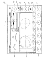
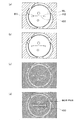
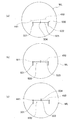
ここで、例えば初期的な表示状態が、図49(a)に示すような位置関係にあるときは、操作者が、液晶表示器11の表示面上を観察して、カーソル500の縦線分501(または502)と横線分503との交点に、検出された隠しマーク441(または442)が一致するように、表示面上に表示された移動アイコン(左移動アイコン11a、右移動アイコン11b、上移動アイコン11c、下移動アイコン11d)を操作し、レンズMLの像を平行移動させる。
Here, for example, when the initial display state is in a positional relationship as shown in FIG. 49A, the operator observes the display surface of the
そして、隠しマーク441(または442)と、カーソル500の縦線分501(または502)と横線分503との交点とが、表示面上で一致した状態で、カーソル500の横線分503と検出された水平線450とが重ならず、一方が他方に対して傾斜しているとき(図49(b))は、操作者は、さらに、回転アイコン(反時計回りアイコン11e、時計回りアイコン11f)を操作して、レンズMLの像を回転させ、カーソル500の横線分503と水平線450とを重ね合わせる(図49(c))。
Then, the hidden mark 441 (or 442) and the intersection of the vertical line segment 501 (or 502) and
このとき、中央縦線分504と横線分503との交点の位置が、レンズ吸着治具120の装着位置であるアイポイント位置となり、上述したアイコン操作によるレンズMLの像の平行移動量および回転角度が演算制御回路130に記憶され、この記憶された平行移動量および回転角度だけレンズMLが移動するように、演算制御回路130が取付角設定モータ61等を作動制御する。
At this time, the position of the intersection of the central
これにより、可動アーム80がレンズ吸着治具120を装着させる位置に、レンズMLのアイポイント位置を適切にセットすることができ、この後、アイポイント位置にレンズ吸着治具120を装着すればよい。
Accordingly, the eye point position of the lens ML can be appropriately set at the position where the
なお、上述した累進多焦点レンズMLは、水平線450上にアイポイントが存在するものとして説明したが、アイポイント位置は、必ずしもこのレンズMLの水平線450上に存在するものだけではなく、水平線450の上方(遠用部431)側2mmの位置や、4mmの位置または6mmの位置に設定されているものもある。
The progressive multifocal lens ML described above is described as having an eye point on the
そこで、このようにアイポイント位置が水平線450からずれた位置に存在するレンズMLに対しては、隠しマーク441(または442)と一致させるカーソル500の部分を、このような水平線450からの既知のずれ量(2mm、4mmまたは6mm)に応じて、縦線分501(または502)と補助横線分505(または508)との交点(ずれ量が2mmの場合)、縦線分501(または502)と補助横線分506(または509)との交点(ずれ量が4mmの場合)、または縦線分501(または502)と補助横線分507(または510)との交点(ずれ量62mmの場合)に、それぞれ変更すればよい。
Therefore, for the lens ML in which the eye point position is shifted from the
なお、(4)で説明した隠しマーク441,442の自動検出処理によって、2つの隠しマーク441および442がいずれも検出されなかった場合であっても、隠しマーク441および442の像が肉眼でも全く視認できないようなものは良品とはいえず、本質的に本実施形態のレンズ吸着治具装着装置1による対象レンズMLとはなり得ないため、肉眼で視認することは全く不可能ではない。
Even if neither of the two
そこで、操作者は、表示面上で視認可能の水平線450の延長線上に存在すべき隠しマーク441または442の像を肉眼で探索する。
Therefore, the operator searches for an image of the
そして、前述したように、いずれかの隠しマーク441または442を視認できたときは、上述した図49により説明した操作処理と同様の操作処理を適用することができる。
As described above, when any of the
なお、両方の隠しマーク441,442ともに視認できる場合には、両隠しマーク441,442が、それぞれ対応する縦線分501,502に重なり合うように、移動アイコン(左移動アイコン11a、右移動アイコン11b、上移動アイコン11c、下移動アイコン11d)や、回転アイコン(反時計回りアイコン11e、時計回りアイコン11f)を操作して、レンズMLの像を回転させればよい。
When both the
そして、このような位置決め操作によっても、可動アーム80がレンズ吸着治具120を装着させる位置に、レンズMLのアイポイント位置を適切にセットすることができ、この後、アイポイント位置にレンズ吸着治具120を装着すればよい。
Even by such a positioning operation, the eye point position of the lens ML can be appropriately set at the position where the
なお、表示面上におけるレンズMLの像を移動、回転させるのに代えて、位置決めカーソル500を移動、回転させるようにしてもよい。
Instead of moving and rotating the image of the lens ML on the display surface, the
以上、詳細に説明したように、本実施形態に係るレンズ吸着治具装着装置1およびこの装置1を用いたレンズの位置決め方法によれば、画像処理によって自動的に全ての隠しマーク441,442を検出することができない場合であっても、眼鏡レンズMLを適切に位置決めすることができる。
As described above in detail, according to the lens suction
120 レンズ吸着治具
441 隠しマーク(第一指標)
450 水平線(第二指標)
500 位置決めカーソル
501,502 縦線分
503 横線分
504 中央縦線分
ML 眼鏡レンズ
120
450 Horizon (second indicator)
500
Claims (6)
前記表示手段に、前記所定の間隔と同一間隔を以て縦方向に延びた複数の縦線分と前記複数の縦線分の全てに直交して横方向に延びた横線分とが一体化した位置決めカーソルを、前記眼鏡レンズの像に重畳して表示させるとともに、
前記表示手段に表示された前記眼鏡レンズの像における前記指標の像のうち少なくとも2以上の像と、前記位置決めカーソルの所定部分とが対応するように、前記位置調整手段により前記載置台を位置調整することを特徴とするレンズの位置決め方法。 A position-adjustable mounting table for holding a spectacle lens on which a plurality of first indexes engraved or protruded on the surface with a predetermined interval and a second index printed and displayed based on the first index are formed Position adjusting means for displacing the mounting table in the position adjustable range, imaging means for imaging the spectacle lens held by the mounting table, and an image of the spectacle lens captured by the imaging means. Based on this, the image processing means for detecting the index, the display means for displaying an image, the image of the eyeglass lens captured by the imaging means and the image of the index obtained by the image processing are displayed on the display means. Of a lens used in a lens suction jig mounting apparatus comprising display control means for controlling the display so that the lens suction jig is mounted on the predetermined part of the spectacle lens. A-decided Me method,
A positioning cursor in which a plurality of vertical line segments extending in the vertical direction at the same interval as the predetermined interval and a horizontal line segment extending in the horizontal direction perpendicular to all of the plurality of vertical line segments are integrated in the display means. And superimposed on the image of the spectacle lens,
Position adjustment of the mounting table by the position adjusting means so that at least two of the index images in the spectacle lens image displayed on the display means correspond to a predetermined portion of the positioning cursor A method of positioning a lens.
前記第一指標が、前記縦線分と前記横線分との交点に、または前記縦線分といずれかの前記補助横線分との交点に、重畳されるように、前記載置台を位置調整することを特徴とする請求項2または3に記載のレンズの位置決め方法。 In addition to the two vertical line segments and one horizontal line segment, the cursor is orthogonal to the horizontal line segment, and a portion of the horizontal line segment that is delimited at both ends by the two vertical line segments A central vertical line passing through the middle point and a plurality of auxiliary horizontal lines perpendicular to the two vertical lines and equally spaced,
The position of the mounting table is adjusted so that the first index is superimposed on an intersection of the vertical line segment and the horizontal line segment, or an intersection of the vertical line segment and any one of the auxiliary horizontal line segments. 4. The lens positioning method according to claim 2, wherein the lens is positioned as described above.
前記表示制御手段は、前記所定の間隔と同一間隔を以て縦方向に延びた複数の縦線分と前記複数の縦線分の全てに直交して横方向に延びた横線分とが一体化した位置決めカーソルを、前記眼鏡レンズの像に重畳して、前記表示手段に表示させるように制御することを特徴とするレンズ吸着治具装着装置。 A position-adjustable mounting table for holding a spectacle lens on which a plurality of first indexes engraved or protruded on the surface with a predetermined interval and a second index printed and displayed based on the first index are formed Position adjusting means for displacing the mounting table in the position adjustable range, imaging means for imaging the spectacle lens held by the mounting table, and an image of the spectacle lens captured by the imaging means. Based on the image processing means for detecting the index, a display means for displaying an image, an image of the spectacle lens imaged by the imaging means and an image of the index obtained by the image processing, A lens suction jig mounting device comprising display control means for controlling to display on the means, and jig mounting means for mounting a lens suction jig on a predetermined part of the spectacle lens,
The display control means is a positioning in which a plurality of vertical line segments extending in the vertical direction at the same interval as the predetermined interval and a horizontal line segment extending in the horizontal direction perpendicular to all of the plurality of vertical line segments are integrated. A lens suction jig mounting apparatus, wherein a cursor is controlled to be superimposed on an image of the spectacle lens and displayed on the display means.
In addition to the two vertical line segments and one horizontal line segment, the cursor is orthogonal to the horizontal line segment, and a portion of the horizontal line segment that is delimited at both ends by the two vertical line segments 6. A lens suction jig mounting device according to claim 5, comprising a central vertical line segment passing through a middle point and a plurality of auxiliary horizontal line segments that are orthogonal to the two vertical line segments and are equally spaced. .
Priority Applications (1)
| Application Number | Priority Date | Filing Date | Title |
|---|---|---|---|
| JP2004107763A JP4541017B2 (en) | 2004-03-31 | 2004-03-31 | Lens suction jig mounting device |
Applications Claiming Priority (1)
| Application Number | Priority Date | Filing Date | Title |
|---|---|---|---|
| JP2004107763A JP4541017B2 (en) | 2004-03-31 | 2004-03-31 | Lens suction jig mounting device |
Publications (2)
| Publication Number | Publication Date |
|---|---|
| JP2005292487A true JP2005292487A (en) | 2005-10-20 |
| JP4541017B2 JP4541017B2 (en) | 2010-09-08 |
Family
ID=35325469
Family Applications (1)
| Application Number | Title | Priority Date | Filing Date |
|---|---|---|---|
| JP2004107763A Expired - Fee Related JP4541017B2 (en) | 2004-03-31 | 2004-03-31 | Lens suction jig mounting device |
Country Status (1)
| Country | Link |
|---|---|
| JP (1) | JP4541017B2 (en) |
Cited By (2)
| Publication number | Priority date | Publication date | Assignee | Title |
|---|---|---|---|---|
| JP2009269117A (en) * | 2008-05-07 | 2009-11-19 | Topcon Corp | Lens holding fixture mounting apparatus |
| CN115248104A (en) * | 2021-04-26 | 2022-10-28 | 北京科益虹源光电技术有限公司 | A lens performance detection device and method thereof |
Citations (6)
| Publication number | Priority date | Publication date | Assignee | Title |
|---|---|---|---|---|
| JPS57133015U (en) * | 1981-02-16 | 1982-08-19 | ||
| JPH11295669A (en) * | 1998-04-08 | 1999-10-29 | Menicon Co Ltd | Trial lens |
| JP2001311919A (en) * | 2000-04-28 | 2001-11-09 | Nidek Co Ltd | Cup mounting device |
| JP2002022599A (en) * | 2000-07-06 | 2002-01-23 | Hoya Corp | Image pickup process device for ophthalmic lens |
| JP2002036083A (en) * | 2000-07-24 | 2002-02-05 | Hoya Corp | Layout, block, and working device for eyeglass lens |
| JP2002139713A (en) * | 2000-10-31 | 2002-05-17 | Hoya Corp | Method and device for mounting lens holders of spectacle lens |
-
2004
- 2004-03-31 JP JP2004107763A patent/JP4541017B2/en not_active Expired - Fee Related
Patent Citations (6)
| Publication number | Priority date | Publication date | Assignee | Title |
|---|---|---|---|---|
| JPS57133015U (en) * | 1981-02-16 | 1982-08-19 | ||
| JPH11295669A (en) * | 1998-04-08 | 1999-10-29 | Menicon Co Ltd | Trial lens |
| JP2001311919A (en) * | 2000-04-28 | 2001-11-09 | Nidek Co Ltd | Cup mounting device |
| JP2002022599A (en) * | 2000-07-06 | 2002-01-23 | Hoya Corp | Image pickup process device for ophthalmic lens |
| JP2002036083A (en) * | 2000-07-24 | 2002-02-05 | Hoya Corp | Layout, block, and working device for eyeglass lens |
| JP2002139713A (en) * | 2000-10-31 | 2002-05-17 | Hoya Corp | Method and device for mounting lens holders of spectacle lens |
Cited By (2)
| Publication number | Priority date | Publication date | Assignee | Title |
|---|---|---|---|---|
| JP2009269117A (en) * | 2008-05-07 | 2009-11-19 | Topcon Corp | Lens holding fixture mounting apparatus |
| CN115248104A (en) * | 2021-04-26 | 2022-10-28 | 北京科益虹源光电技术有限公司 | A lens performance detection device and method thereof |
Also Published As
| Publication number | Publication date |
|---|---|
| JP4541017B2 (en) | 2010-09-08 |
Similar Documents
| Publication | Publication Date | Title |
|---|---|---|
| EP1997585B1 (en) | Cup attaching apparatus | |
| KR101442575B1 (en) | Cup attaching apparatus | |
| US7715023B2 (en) | Jig mounting apparatus | |
| CN1921981B (en) | Lens centering and locking device, associated manual centering method and automatic detection method | |
| KR101423768B1 (en) | Eyeglass lens processing system | |
| KR101381121B1 (en) | Cup attaching apparatus | |
| JP4822318B2 (en) | Lens position specifying method and lens suction jig mounting device used for lens suction jig mounting device | |
| KR101408122B1 (en) | Cup attaching apparatus | |
| JP4583869B2 (en) | Lens positioning method and lens suction jig mounting device used in lens suction jig mounting device | |
| JP4541017B2 (en) | Lens suction jig mounting device | |
| JP5204544B2 (en) | Lens holding jig mounting device | |
| CN1938636A (en) | Fixture Mounting Device | |
| JP4104297B2 (en) | Cup mounting device | |
| JPH11216650A (en) | Centering device | |
| JP4360966B2 (en) | Lens attachment jig automatic mounting device | |
| JP5147173B2 (en) | Inspection tray | |
| JP4494844B2 (en) | Automatic jig mounting device for spectacle lens and suction jig automatic mounting method for spectacle lens | |
| JP4739771B2 (en) | Eyeglass lens suction jig mounting device | |
| JP2019100928A (en) | Lens shape measurement device | |
| JP2019098484A (en) | Axial alignment device, device for lens processing, spectacle lens processing system, and spectacle lens processing method | |
| JP2005288630A (en) | Automatic lens adsorption device | |
| JP4536423B2 (en) | Automatic lens adsorption device | |
| JP2006284216A (en) | Suction jig mounting device for aspheric spectacle lens and method for determining suction jig mounting position | |
| KR101497691B1 (en) | Glasses lens processing equipment | |
| JP2005292489A (en) | Method and apparatus for determining presence / absence of eyeglass lens |
Legal Events
| Date | Code | Title | Description |
|---|---|---|---|
| A621 | Written request for application examination |
Free format text: JAPANESE INTERMEDIATE CODE: A621 Effective date: 20070330 |
|
| A131 | Notification of reasons for refusal |
Free format text: JAPANESE INTERMEDIATE CODE: A131 Effective date: 20100106 |
|
| A521 | Request for written amendment filed |
Free format text: JAPANESE INTERMEDIATE CODE: A523 Effective date: 20100203 |
|
| A131 | Notification of reasons for refusal |
Free format text: JAPANESE INTERMEDIATE CODE: A131 Effective date: 20100406 |
|
| A521 | Request for written amendment filed |
Free format text: JAPANESE INTERMEDIATE CODE: A523 Effective date: 20100603 |
|
| TRDD | Decision of grant or rejection written | ||
| A01 | Written decision to grant a patent or to grant a registration (utility model) |
Free format text: JAPANESE INTERMEDIATE CODE: A01 Effective date: 20100622 |
|
| A01 | Written decision to grant a patent or to grant a registration (utility model) |
Free format text: JAPANESE INTERMEDIATE CODE: A01 |
|
| A61 | First payment of annual fees (during grant procedure) |
Free format text: JAPANESE INTERMEDIATE CODE: A61 Effective date: 20100623 |
|
| R150 | Certificate of patent or registration of utility model |
Ref document number: 4541017 Country of ref document: JP Free format text: JAPANESE INTERMEDIATE CODE: R150 Free format text: JAPANESE INTERMEDIATE CODE: R150 |
|
| FPAY | Renewal fee payment (event date is renewal date of database) |
Free format text: PAYMENT UNTIL: 20130702 Year of fee payment: 3 |
|
| R250 | Receipt of annual fees |
Free format text: JAPANESE INTERMEDIATE CODE: R250 |
|
| R250 | Receipt of annual fees |
Free format text: JAPANESE INTERMEDIATE CODE: R250 |
|
| R250 | Receipt of annual fees |
Free format text: JAPANESE INTERMEDIATE CODE: R250 |
|
| R250 | Receipt of annual fees |
Free format text: JAPANESE INTERMEDIATE CODE: R250 |
|
| R250 | Receipt of annual fees |
Free format text: JAPANESE INTERMEDIATE CODE: R250 |
|
| R250 | Receipt of annual fees |
Free format text: JAPANESE INTERMEDIATE CODE: R250 |
|
| R250 | Receipt of annual fees |
Free format text: JAPANESE INTERMEDIATE CODE: R250 |
|
| R250 | Receipt of annual fees |
Free format text: JAPANESE INTERMEDIATE CODE: R250 |
|
| LAPS | Cancellation because of no payment of annual fees |