JP2005292400A - Fiber-optic cable - Google Patents

Fiber-optic cable Download PDF

Info

Publication number
JP2005292400A
JP2005292400A JP2004106182A JP2004106182A JP2005292400A JP 2005292400 A JP2005292400 A JP 2005292400A JP 2004106182 A JP2004106182 A JP 2004106182A JP 2004106182 A JP2004106182 A JP 2004106182A JP 2005292400 A JP2005292400 A JP 2005292400A
Authority
JP
Japan
Prior art keywords
optical fiber
cable
fiber unit
unit
optical
Prior art date
Legal status (The legal status is an assumption and is not a legal conclusion. Google has not performed a legal analysis and makes no representation as to the accuracy of the status listed.)
Pending
Application number
JP2004106182A
Other languages
Japanese (ja)
Inventor
Satoru Shiobara
悟 塩原
Takeshi Shimomichi
毅 下道
Keiji Ohashi
圭二 大橋
Current Assignee (The listed assignees may be inaccurate. Google has not performed a legal analysis and makes no representation or warranty as to the accuracy of the list.)
Fujikura Ltd
Original Assignee
Fujikura Ltd
Priority date (The priority date is an assumption and is not a legal conclusion. Google has not performed a legal analysis and makes no representation as to the accuracy of the date listed.)
Filing date
Publication date
Application filed by Fujikura Ltd filed Critical Fujikura Ltd
Priority to JP2004106182A priority Critical patent/JP2005292400A/en
Publication of JP2005292400A publication Critical patent/JP2005292400A/en
Pending legal-status Critical Current

Links

Images

Abstract

<P>PROBLEM TO BE SOLVED: To avoid breaking a fiber-optic cable when cutting its sheath and improve its stripping. <P>SOLUTION: The fiber-optic cable 1 is composed of an optical fiber 3, an optical fiber unit 9 covered all around with UV curing resin 7 and bundled, tension members 5 arranged both sides along the above optical fiber unit 9, and the length of an optical element 13 covering the above optical fiber unit 9 and tension members 5 with a cable sheath 11. Further, it has cutouts 15 on the surface of the cable sheath 11, in the plane normal to the above lengthwise direction, and outside the above optical fiber unit 9 in the 2nd direction perpendicularly crossing the 1st direction connecting the above tension members 5. <P>COPYRIGHT: (C)2006,JPO&NCIPI

Description

この発明は、引き落とし光ファイバケーブルに関する。   The present invention relates to a drawn optical fiber cable.

構内、架空用の引き落とし光ファイバケーブル(ドロップケーブル)としては1、2心程度が通常であるが、FTTH(Fiber to the home)の拡大と共に小規模マンションやビルなどに、4〜10心程度の多心化の需要が予想される。   About 1 or 2 cores are usually used as optical fiber cables (drop cables) for premises and aerials. However, with the expansion of FTTH (Fiber to the home), it is about 4 to 10 cores for small-scale condominiums and buildings. Multi-center demand is expected.

また、後分岐作業性の観点から、収納される光ファイバとしては、単独の素線(または2心程度のテープ光ファイバ心線)を用いたものが有効と考える。   From the standpoint of post-branch workability, it is considered effective to use a single strand (or a tape optical fiber core of about 2 cores) as the optical fiber to be stored.

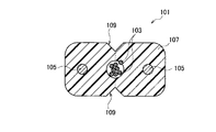
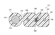
単光ファイバ心線を入れた多心の引き落とし光ファイバケーブルを設計しようとした場合、ルースチューブケーブルやスロットケーブルなどが考えられるが、いずれも外径が大きくなる上コスト高であるため、図10に示されているような細径でシンプルなドロップ・インドアケーブル101を踏襲したケーブルが有効である。すなわち、図10において、ドロップ・インドアケーブル101は例えば8本の光ファイバ103と、この近傍に平行で両脇に配置された光エレメント用抗張力体105とをケーブルシース107で被覆したもので、前記各光エレメント用抗張力体105を結んだ方向に対して直交した方向の前記光ファイバ103の両側(図10において上下)におけるケーブルシース107の表面にノッチ部109を形成せしめたものである。上記の光ファイバ103としては、単数又は複数の光ファイバ素線又は光ファイバテープ心線を収納した光ファイバケーブルがある(例えば、特許文献1参照)。   When an attempt is made to design a multi-fiber dropping optical fiber cable including a single optical fiber, a loose tube cable, a slot cable, and the like are conceivable. A cable that follows the simple drop-indoor cable 101 with a small diameter as shown in FIG. That is, in FIG. 10, a drop indoor cable 101 is, for example, a structure in which eight optical fibers 103 and a tensile element 105 for an optical element arranged in parallel on both sides in the vicinity thereof are covered with a cable sheath 107. A notch 109 is formed on the surface of the cable sheath 107 on both sides (up and down in FIG. 10) of the optical fiber 103 in a direction perpendicular to the direction in which the optical element strength members 105 are connected. As said optical fiber 103, there exists an optical fiber cable which accommodated the single or several optical fiber strand or the optical fiber tape core wire (for example, refer patent document 1).

また、図11を参照するに、光ファイバドロップケーブル111は、上記のドロップ・インドアケーブル101のケーブルシース107に、支持線113をケーブルシース107と同じ樹脂のシース材115で被覆した長尺のケーブル支持線部117を互いに平行に首部119を介して一体化されたものである。図11では例えば8本の光ファイバ103が収納されているが、単数又は複数の光ファイバ素線又は光ファイバテープ心線を収納した光ファイバケーブルもある(例えば、特許文献2参照)。   Referring to FIG. 11, the optical fiber drop cable 111 is a long cable in which the cable sheath 107 of the drop / indoor cable 101 is covered with the support wire 113 with the same sheath material 115 as the cable sheath 107. The support line portions 117 are integrated in parallel with each other via a neck portion 119. In FIG. 11, for example, eight optical fibers 103 are accommodated, but there is also an optical fiber cable that accommodates one or a plurality of optical fiber strands or optical fiber ribbons (for example, see Patent Document 2).

上述した従来のドロップ・インドアケーブル101および光ファイバドロップケーブル111は、ノッチ部109からケーブルシース107を手で切り裂いて、内部の光ファイバ103を取り出して使用することができる。   The conventional drop indoor cable 101 and the optical fiber drop cable 111 described above can be used by tearing the cable sheath 107 from the notch portion 109 by hand and taking out the internal optical fiber 103.

FTTH配線に求められる機能として、光学特性の他に信頼性の高い光伝送路を提供するために、雷サージ電流の遮断や、過大な外的張力の遮断などが求められる。この機能を満たすために、架空光ケーブルのクロージャ等のアクセス点から住宅側に引き込まれる光ファイバドロップケーブル111と、住宅内において光アクセス装置に配線されるドロップ・インドアケーブル101が、主として住宅壁面の屋外成端光キャビネット内において接続している。   As functions required for FTTH wiring, in order to provide a highly reliable optical transmission line in addition to optical characteristics, lightning surge current interruption and excessive external tension interruption are required. In order to satisfy this function, an optical fiber drop cable 111 drawn into the house side from an access point such as a closure of an aerial optical cable and a drop indoor cable 101 wired to the optical access device in the house are mainly outdoor on the wall surface of the house. It is connected in the termination optical cabinet.

このとき、必要機能を満たすためには光ファイバドロップケーブル111の光エレメント用抗張力体105を一旦切断した後に住宅内に引き込まなければならない。しかし、光ファイバドロップケーブル111の断面構造がタイトであるために、光ファイバ103に損傷を与えることなく光エレメント用抗張力体105を切断するには光ファイバ103も同時に切断しなければならず、この切断した光ファイバ103はドロップ・インドアケーブル101の光ファイバ103と接続点により接続していた。   At this time, in order to satisfy the required function, the optical element strength member 105 of the optical fiber drop cable 111 must be once cut and then drawn into the house. However, since the cross-sectional structure of the optical fiber drop cable 111 is tight, the optical fiber 103 must also be cut at the same time in order to cut the optical element tensile member 105 without damaging the optical fiber 103. The cut optical fiber 103 was connected to the optical fiber 103 of the drop indoor cable 101 by a connection point.

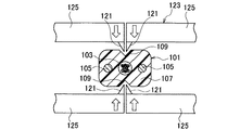
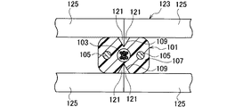
近年、上記のアクセス点から光アクセス装置間に接続点を設けないように配線するために、図12〜図14に示されているように、ドロップ・インドアケーブル101は、その長手方向の任意の中間点が、爪部121が付いたドロップデタッチャー123(以下、単に「デタッチャー」という)と称する口出し治具を使用することにより、光ファイバ103に損傷を与えることなく光エレメント用抗張力体105を分離し切断することが可能となっている。   In recent years, in order to perform wiring so that no connection point is provided between the access point and the optical access device, as shown in FIGS. By using a lead jig called a drop detacher 123 (hereinafter simply referred to as “detacher”) having a claw portion 121 at the midpoint, the optical element tensile strength member 105 without damaging the optical fiber 103. Can be separated and cut.

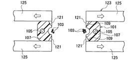
すなわち、図12及び図13に示されているように、ドロップ・インドアケーブル101のノッチ部109を中心として、光エレメント用抗張力体105がデタッチャー123の左右のクランプ125でケーブルシース107の上から挟んで固定されると共に左右のクランプ125の爪部121がノッチ部109に当てられた後に、図14に示されているように左右のクランプ125が矢印の左右方向に広げられる。これにより、ノッチ部109から光ファイバ103のあるケーブル中央部までケーブルシース107が裂けて光ファイバ103が剥ぎ出される。   That is, as shown in FIGS. 12 and 13, the optical element strength member 105 is sandwiched from above the cable sheath 107 by the left and right clamps 125 of the detacher 123 around the notch 109 of the drop indoor cable 101. After the claw portions 121 of the left and right clamps 125 are brought into contact with the notch portions 109, the left and right clamps 125 are spread in the left-right direction of the arrow as shown in FIG. As a result, the cable sheath 107 is torn from the notch 109 to the center of the cable where the optical fiber 103 is located, and the optical fiber 103 is peeled off.

光エレメント用抗張力体105が光ファイバ103から十分に分離された状態で、光エレメント用抗張力体105の切断が行われる。上記の剥ぎ出された光ファイバ103は屋外成端光キャビネット内に収納される。
特開2003−202471号公報 特開2000−28877号公報
With the optical element tensile member 105 sufficiently separated from the optical fiber 103, the optical element tensile member 105 is cut. The stripped optical fiber 103 is housed in an outdoor termination optical cabinet.
JP 2003-202471 A JP 2000-28877 A

ところで、従来の光ファイバケーブル101、111では、デタッチャー123により口出し又は中間後分岐が行われる際に、デタッチャー123の爪部121がノッチ部109に当てられて、ノッチ部109からケーブルシース107が左右に引き裂かれる際に、図10に示されているように、光ファイバ103の全体あるいは一部がケーブルシース107に埋没しているか、あるいは埋没まではいかなくても光ファイバ103とケーブルシース107の間の密着度が非常に高い場合は、光ファイバ103が巻き込まれて破断する恐れがあるという問題点があった。   By the way, in the conventional optical fiber cables 101 and 111, when the detacher 123 is opened or the intermediate rear branch is performed, the claw portion 121 of the detacher 123 is applied to the notch portion 109, and the cable sheath 107 is left and right from the notch portion 109. 10, as shown in FIG. 10, the whole or a part of the optical fiber 103 is buried in the cable sheath 107, or the optical fiber 103 and the cable sheath 107 are not buried. When the degree of adhesion between the two is very high, there is a problem that the optical fiber 103 may be caught and broken.

また、デタッチャー123によりケーブルシース107に切れ込みを入れた後でも、必要な長さだけ口出しもしくは中間後分岐する場合は、ケーブルシース107を手で左右に分けることがある。このとき、ケーブルシース107に密着した光ファイバ103がケーブルシース107ごと大きく曲げられたり、光ファイバ103が破断する可能性があるという問題点があった。   In addition, even after the cable sheath 107 is cut by the detacher 123, the cable sheath 107 may be divided into left and right by hand if the necessary length is opened or branched after the middle. At this time, there is a problem that the optical fiber 103 in close contact with the cable sheath 107 may be greatly bent together with the cable sheath 107 or the optical fiber 103 may be broken.

また、ノッチ部109からケーブルシース107を引き裂いて光ファイバ103を取り出す際に、光ファイバ103がケーブルシース107の切断面で擦られたり、挟み込まれたりするために、光ファイバ103が誤って切断されるという問題点があった。   Further, when the optical fiber 103 is taken out by tearing the cable sheath 107 from the notch 109, the optical fiber 103 is accidentally cut because the optical fiber 103 is rubbed or pinched by the cut surface of the cable sheath 107. There was a problem that.

この発明は上述の課題を解決するためになされたものである。   The present invention has been made to solve the above-described problems.

この発明の光ファイバケーブルは、光ファイバと、
この光ファイバの周囲に紫外線硬化型樹脂を被覆して一束化した光ファイバユニットと、
この光ファイバユニットの長手方向に沿って光ファイバユニットの両側に配置された抗張力体と、
前記光ファイバユニット、及び抗張力体を被覆するケーブルシースであって、前記長手方向に垂直な面内において前記抗張力体を結ぶ第1方向に直交する第2方向の前記光ファイバユニットの外側におけるケーブルシースの表面にノッチ部が形成されたケーブルシースと、
を備える長尺の光エレメント部を有することを特徴とするものである。
An optical fiber cable of the present invention includes an optical fiber,
An optical fiber unit in which an ultraviolet curable resin is coated around the optical fiber and bundled,
Strength members disposed on both sides of the optical fiber unit along the longitudinal direction of the optical fiber unit,
A cable sheath covering the optical fiber unit and a tensile body, and a cable sheath outside the optical fiber unit in a second direction orthogonal to a first direction connecting the tensile bodies in a plane perpendicular to the longitudinal direction. A cable sheath having a notch portion formed on the surface thereof,
It has a long optical element part provided with.

また、この発明の光ファイバケーブルは、前記光ファイバケーブルにおいて、前記光ファイバユニットの紫外線硬化型樹脂は、当該紫外線硬化型樹脂の硬化後のヤング率が1MPaを超え、且つ100MPa未満に構成してなることが好ましい。   In the optical fiber cable of the present invention, in the optical fiber cable, the ultraviolet curable resin of the optical fiber unit may have a Young's modulus after curing of the ultraviolet curable resin of more than 1 MPa and less than 100 MPa. It is preferable to become.

また、この発明の光ファイバケーブルは、前記光ファイバケーブルにおいて、前記光ファイバユニットが、前記長手方向に垂直な面内において紫外線硬化型樹脂の外周面に少なくとも1箇所の第2ノッチ部を有してなることが好ましい。   In the optical fiber cable of the present invention, in the optical fiber cable, the optical fiber unit has at least one second notch portion on the outer peripheral surface of the ultraviolet curable resin in a plane perpendicular to the longitudinal direction. It is preferable that

また、この発明の光ファイバケーブルは、前記光ファイバケーブルにおいて、前記光ファイバユニットが、2つの第2ノッチ部を有すると共に、前記2つの第2ノッチ部を結ぶ線を第2方向に向けて配置してなることが好ましい。   In the optical fiber cable of the present invention, in the optical fiber cable, the optical fiber unit has two second notch portions, and a line connecting the two second notch portions is arranged in the second direction. It is preferable that

また、この発明の光ファイバケーブルは、前記光ファイバケーブルにおいて、前記光ファイバユニットが、2つの第2ノッチ部を有すると共に、前記2つの第2ノッチ部を結ぶ線を第1方向に向けて配置してなることが好ましい。   In the optical fiber cable of the present invention, in the optical fiber cable, the optical fiber unit has two second notch portions, and a line connecting the two second notch portions is arranged in the first direction. It is preferable that

また、この発明の光ファイバケーブルは、前記光ファイバケーブルにおいて、支持線をシースで被覆した長尺のケーブル支持線部であって、前記光エレメント部に平行に配置され且つ一体化されたケーブル支持線部を有することが好ましい。   The optical fiber cable according to the present invention is a long cable support line portion in which the support wire is covered with a sheath in the optical fiber cable, and is arranged in parallel with the optical element portion and integrated with the cable support. It is preferable to have a line part.

また、この発明の光ファイバケーブルは、前記光ファイバケーブルにおいて、前記光ファイバは、単数または複数の素線または心線を有することが好ましい。   Moreover, the optical fiber cable of this invention WHEREIN: It is preferable that the said optical fiber has a single or several strand or a core wire in the said optical fiber cable.

以上のごとき課題を解決するための手段から理解されるように、この発明によれば、光ファイバの周囲に紫外線硬化型樹脂を被覆して一束化して光ファイバユニットを形成したので、光ファイバが紫外線硬化型樹脂により保護されているため、ノッチ部からケーブルシースを引き裂いて光ファイバを取り出す際に、光ファイバがケーブルシースの切断面で擦られたり、挟み込まれたりすることを防止できる。しかも、紫外線硬化型樹脂は指先でしごくことにより容易に破壊できるので、光ファイバを光ファイバユニットから容易に分離して取り出すことができる。   As understood from the means for solving the above problems, according to the present invention, an optical fiber unit is formed by coating an ultraviolet curable resin around the optical fiber to form a bundle. Is protected by the ultraviolet curable resin, it is possible to prevent the optical fiber from being rubbed or pinched by the cut surface of the cable sheath when the cable sheath is torn from the notch portion and the optical fiber is taken out. Moreover, since the ultraviolet curable resin can be easily broken by squeezing it with a fingertip, the optical fiber can be easily separated from the optical fiber unit and taken out.

また、光ファイバユニットに用いられる紫外線硬化型樹脂は、ケーブルシースから光ファイバを取り出すなどの取扱いに十分な機械的強度を有し、且つ光ファイバを容易に単心に分離可能とするために適度な柔らかさが必要である。この点、紫外線硬化型樹脂の硬化後のヤング率が1MPaを超え、且つ100MPa未満の範囲にある場合は、ユニット取出し性と光ファイバの分離性のいずれも良好であり、光ファイバの誤切断が生じる可能性をなくすことができる。   In addition, the ultraviolet curable resin used in the optical fiber unit has a mechanical strength sufficient for handling such as taking out the optical fiber from the cable sheath, and is suitable for easily separating the optical fiber into a single core. Softness is necessary. In this respect, when the Young's modulus after curing of the ultraviolet curable resin is in the range of more than 1 MPa and less than 100 MPa, both the unit take-out property and the separation property of the optical fiber are good, and the optical fiber is erroneously cut. The possibility of occurring can be eliminated.

以下、この発明の実施の形態について図面を参照して詳細に説明する。   Hereinafter, embodiments of the present invention will be described in detail with reference to the drawings.

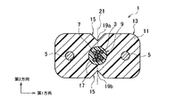
図1を参照するに、この発明の第1の実施形態の光ファイバケーブル1は、例えば複数の光ファイバ3を有している。この実施の形態では、光ファイバ3として8本の光ファイバ素線が配置されている。なお、各光ファイバ素線3は、例えば125μmφの石英ガラスの外周にUV樹脂で250μmφに被覆されたものである。   Referring to FIG. 1, an optical fiber cable 1 according to the first embodiment of the present invention has, for example, a plurality of optical fibers 3. In this embodiment, eight optical fiber strands are arranged as the optical fiber 3. Each optical fiber 3 is made of, for example, a 125 μmφ quartz glass whose outer periphery is coated with a UV resin to 250 μmφ.

上記の光ファイバ3の長手方向に沿って光ファイバ3の両側(図1において左右)の近傍位置に、光ファイバ3に平行して、光エレメント用抗張力体5が配置されている。   In the vicinity of both sides (left and right in FIG. 1) of the optical fiber 3 along the longitudinal direction of the optical fiber 3, the optical element strength member 5 is disposed in parallel with the optical fiber 3.

さらに、 上記の1本あるいは複数本の光ファイバ3は、予め、前記光ファイバ3の長手方向に沿って光ファイバ3の周囲に、手で取り外しが可能なほどのヤング率の小さい紫外線硬化型樹脂7(以下、単に「UV樹脂」という)で充填することにより、光ファイバユニット9が形成されている。   Further, the one or a plurality of optical fibers 3 are preliminarily provided around the optical fiber 3 along the longitudinal direction of the optical fiber 3 and have a small Young's modulus that can be removed by hand. The optical fiber unit 9 is formed by filling with 7 (hereinafter, simply referred to as “UV resin”).

上記の光ファイバ3とUV樹脂7とからなる光ファイバユニット9、及び光エレメント用抗張力体5は、熱可塑性樹脂からなるケーブルシース11で被覆され、長尺の光エレメント部13を構成する。なお、この実施の形態では、ケーブルシース11として黒色ポリエチレン樹脂が用いられている。   The optical fiber unit 9 made of the optical fiber 3 and the UV resin 7 and the optical element strength member 5 are covered with a cable sheath 11 made of a thermoplastic resin to constitute a long optical element portion 13. In this embodiment, a black polyethylene resin is used as the cable sheath 11.

上記の光ファイバユニット9の長手方向に直交する面内において、光エレメント用抗張力体5を結ぶ配置方向(第1方向)に直交する方向(図1において上下方向;第2方向)において光ファイバユニット9の両外側(図1において上下)に位置するケーブルシース11の表面には、ノッチ部15が形成されている。なお、前記光ファイバユニット9はケーブルシース11内に形成した中空部17内に収容されるように配置されている。   In the plane orthogonal to the longitudinal direction of the optical fiber unit 9 described above, the optical fiber unit in a direction (vertical direction; second direction in FIG. 1) orthogonal to the arrangement direction (first direction) connecting the optical element strength members 5. A notch portion 15 is formed on the surface of the cable sheath 11 located on both outer sides (upper and lower sides in FIG. 1) 9. The optical fiber unit 9 is disposed so as to be accommodated in a hollow portion 17 formed in the cable sheath 11.

また、口出し又は中間後分岐性を良好にするために、ノッチ部15の頂点19a、19bを結ぶ面21(直線)が、前記光ファイバユニット9によってケーブルシース11に形成される孔の形状の境界線と交差するように設けられている。   In addition, in order to improve the outlet or intermediate post-branching property, the surface 21 (straight line) connecting the vertices 19a and 19b of the notch 15 is a boundary of the shape of the hole formed in the cable sheath 11 by the optical fiber unit 9. It is provided to intersect the line.

上記構成においては、予め、光ファイバ3はヤング率の小さいUV樹脂7で充填して一束化されて光ファイバユニット9が形成されているので、ケーブルシース11がノッチ部15から引裂かれる時(口出し又は中間後分岐時)に、光ファイバ3が巻き込まれて破断する危険性はなくなる。すなわち、光ファイバ3がUV樹脂7により保護されているので、ケーブルシース11がノッチ部15から引き裂かれて光ファイバ3が取り出される際に、光ファイバ3がケーブルシース11の切断面で擦られたり、挟み込まれたりすることを防止できる。   In the above configuration, since the optical fiber 3 is previously filled with the UV resin 7 having a low Young's modulus and bundled to form the optical fiber unit 9, the cable sheath 11 is torn from the notch portion 15 ( There is no risk of the optical fiber 3 being caught and broken at the time of dispensing or branching after intermediate. That is, since the optical fiber 3 is protected by the UV resin 7, the optical fiber 3 is rubbed against the cut surface of the cable sheath 11 when the cable sheath 11 is torn from the notch portion 15 and the optical fiber 3 is taken out. , And can be prevented from being caught.

しかも、UV樹脂7は指先でしごくことにより容易に破壊できるので、ケーブルシース11を切り裂いた後に、光ファイバユニット9のUV樹脂7を手で切り裂くことにより、個々の光ファイバ3を光ファイバユニット9から容易に分離して取り出すことができる。   In addition, since the UV resin 7 can be easily broken by squeezing it with a fingertip, after the cable sheath 11 is cut, the UV resin 7 of the optical fiber unit 9 is cut by hand, whereby each individual optical fiber 3 is cut into the optical fiber unit 9. Can be easily separated and removed.

また、ケーブルシース11に切れ込みを入れた後に、必要な長さだけ口出しもしくは中間後分岐する場合は、ケーブルシース11を左右に分けることがあるが、ケーブルシース11から光ファイバユニット9を取り出しながら、容易にケーブルシース11を引き裂くことができ、上述したように光ファイバユニット9の中から光ファイバ3を簡単に取り出すことができる。したがって、光ファイバ3がケーブルシース11に埋没、あるいは密着してケーブルシース11ごと大きく曲げられて光ファイバ3が破断するという従来の事態を避けることができる。   In addition, when the cable sheath 11 is cut out, the cable sheath 11 may be divided into left and right when the necessary length is opened or branched after the middle, while the optical fiber unit 9 is taken out from the cable sheath 11 The cable sheath 11 can be easily torn and the optical fiber 3 can be easily taken out from the optical fiber unit 9 as described above. Therefore, it is possible to avoid the conventional situation in which the optical fiber 3 is buried in or closely adhered to the cable sheath 11 and greatly bent together with the cable sheath 11 and the optical fiber 3 is broken.

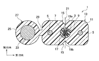
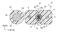
図2は、この発明の第2の実施形態の光ファイバケーブル1を示す。この光ファイバケーブル1は、図1と同様な長尺の光エレメント部13を有する。光ファイバケーブル1は、支持線23をシース25で被覆した長尺のケーブル支持線部27をさらに備える。支持線23は、例えば鋼線からなる。   FIG. 2 shows an optical fiber cable 1 according to a second embodiment of the present invention. The optical fiber cable 1 has a long optical element portion 13 similar to that shown in FIG. The optical fiber cable 1 further includes a long cable support line portion 27 in which the support line 23 is covered with a sheath 25. The support wire 23 is made of, for example, a steel wire.

シース25は、熱可塑性樹脂としての例えば黒色ポリエチレン樹脂であり、ケーブルシース11と一体的に成形される。よって、ケーブル支持線部27は、光エレメント部13に対して平行に首部29を介して一体化されている。なお、光ファイバ3の長手方向に直交する面内において、前記支持線23、一対の光エレメント用抗張力体5及び光ファイバユニット9は前記第1方向に沿って整列されて配置される。   The sheath 25 is, for example, black polyethylene resin as a thermoplastic resin, and is molded integrally with the cable sheath 11. Therefore, the cable support line portion 27 is integrated with the optical element portion 13 in parallel via the neck portion 29. In the plane orthogonal to the longitudinal direction of the optical fiber 3, the support line 23, the pair of optical element strength members 5 and the optical fiber unit 9 are arranged in alignment along the first direction.

上記構成により、この第2の実施の形態の光ファイバケーブル1は、前記光エレメント部13に、支持線23をシース25で被覆した長尺のケーブル支持線部27が互いに平行に首部29を介して一体化されていることにより、光ファイバドロップケーブルとして利用することができると共に、図1における効果と同様の効果を有する。   With the above configuration, in the optical fiber cable 1 of the second embodiment, the long cable support line portion 27 in which the support wire 23 is covered with the sheath 25 is parallel to the optical element portion 13 via the neck portion 29. 1 can be used as an optical fiber drop cable, and has the same effect as that in FIG.

前述した第1,第2の実施の形態の光ファイバケーブル1では、光ファイバ3としては、8本の光ファイバ素線が用いられているが、複数の素線の他に単数の素線または光ファイバ心線、光ファイバコードを用いるようにしても構わない。特に、0.25mmの素線が最も好適に使用されるが、0.4〜0.9mm程度の単心線なども使用される。   In the optical fiber cables 1 of the first and second embodiments described above, eight optical fiber strands are used as the optical fiber 3, but in addition to a plurality of strands, a single strand or You may make it use an optical fiber core wire and an optical fiber cord. In particular, a strand of 0.25 mm is most preferably used, but a single core of about 0.4 to 0.9 mm is also used.

また、前記光エレメント用抗張力体5としては、鋼線やFRPなどが好適に使用されると共に支持線23は鋼線が使用される。   As the optical element strength member 5, a steel wire, FRP, or the like is preferably used, and the support wire 23 is a steel wire.

なお、上述した第1,第2の実施の形態では、ケーブルシース11の中空部17内に、光ファイバユニット9が充実されるほどに収容されるように構成されているが、押出成形時に中空部17を設けずに光ファイバユニット9の外周とケーブルシース11との間が殆ど隙間なく押し出されて密着した状態であっても構わない。この場合は、図1に示されているように、光ファイバ3の長手方向に直交する面内において、各ノッチ部15を結ぶ直線(面)21は、前記光ファイバユニット9によってケーブルシース11に形成される孔(中空部17に相当する部分)の形状の境界線と交わるようにすることが、光ファイバユニット9内の光ファイバ3の口出し性を良くするという点で望ましい。   In the first and second embodiments described above, the optical fiber unit 9 is accommodated in the hollow portion 17 of the cable sheath 11 so as to be filled. There may be a state in which the outer periphery of the optical fiber unit 9 and the cable sheath 11 are pushed and closely contacted with each other without providing the portion 17. In this case, as shown in FIG. 1, in the plane orthogonal to the longitudinal direction of the optical fiber 3, a straight line (surface) 21 connecting the notches 15 is connected to the cable sheath 11 by the optical fiber unit 9. Crossing the boundary line of the shape of the hole to be formed (portion corresponding to the hollow portion 17) is desirable in terms of improving the lead-out property of the optical fiber 3 in the optical fiber unit 9.

つぎに、図2に示す光ファイバケーブル1の製造方法について説明する。   Next, a method for manufacturing the optical fiber cable 1 shown in FIG. 2 will be described.

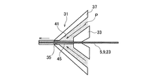
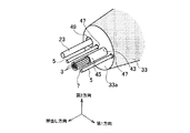
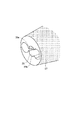
図3を参照するに、押出ヘッド31の断面図が示されており、この押出ヘッド31の中心部には図4に示されているようなニップル部33が設けられていると共に、このニップル部33の外周には図5に示されているように、例えば図2の光ファイバケーブル1の断面の外周形状とほぼ同形状のダイス孔35を備えたダイス部37が設けられている。この場合、ダイス孔35にはノッチ部15を形成するための突起部39a,39bが光エレメント部13のほぼ中央位置の図2のケーブル1のノッチ部15に該当する位置に設けられている。このダイス部37と前記ニップル部33との間にはシースとしての熱可塑性樹脂Pが押し出される流路41が設けられている。   Referring to FIG. 3, there is shown a cross-sectional view of the extrusion head 31, and a nipple portion 33 as shown in FIG. As shown in FIG. 5, for example, a die portion 37 having a die hole 35 having substantially the same shape as the outer peripheral shape of the cross section of the optical fiber cable 1 of FIG. 2 is provided on the outer periphery of 33. In this case, protrusions 39a and 39b for forming the notch 15 are provided in the die hole 35 at a position corresponding to the notch 15 of the cable 1 in FIG. Between this die part 37 and the said nipple part 33, the flow path 41 by which the thermoplastic resin P as a sheath is extruded is provided.

また、前記ニップル部33には図4に示されているように、光ファイバユニット9が通る通り穴としての例えばニップル孔43が形成されており、このニップル孔43は断面ほぼ円形状であると共にニップル孔43の前方(図4において左方)には押出し方向(図3において左方向)に向かってダイス孔35の先端まで延伸する断面ほぼ円形状のパイプ45が連結されている。また、ニップル孔43の図4において第1方向の両外側には光エレメント用抗張力体5が通るニップル孔47が設けられ、図4において左側のニップル孔47の外側(第1方向の左側)には支持線23が通るニップル孔49が形成されている。   In addition, as shown in FIG. 4, the nipple portion 33 is formed with, for example, a nipple hole 43 as a through hole through which the optical fiber unit 9 passes. The nipple hole 43 has a substantially circular cross section. A pipe 45 having a substantially circular cross section is connected to the front of the nipple hole 43 (left side in FIG. 4) extending in the extrusion direction (left direction in FIG. 3) to the tip of the die hole 35. Further, nipple holes 47 through which the optical element strength member 5 passes are provided on both outer sides in the first direction in FIG. 4 of the nipple holes 43, and on the outer side of the nipple hole 47 on the left side (left side in the first direction) in FIG. A nipple hole 49 through which the support line 23 passes is formed.

上記構成により、図3、図4において右側に設けられ、予め8本の光ファイバ3とその周囲に充填されたUV樹脂7とから成形された光ファイバユニット9、2本の光エレメント用抗張力体5、支持線23がそれぞれ引き出され、押出ヘッド31内へ送られる。光ファイバユニット9は押出ヘッド31内のニップル部33のニップル孔43およびパイプ45を通るように送られる。   With the above configuration, an optical fiber unit 9 provided on the right side in FIG. 3 and FIG. 4 and previously formed from eight optical fibers 3 and a UV resin 7 filled therearound, and two strength members for optical elements. 5 and the support line 23 are each pulled out and sent into the extrusion head 31. The optical fiber unit 9 is sent through the nipple hole 43 and the pipe 45 of the nipple portion 33 in the extrusion head 31.

また、2本の光エレメント用抗張力体5はニップル部33の各ニップル孔47を通って、また1本の支持線23はニップル孔49を通って図3、図4において左方向へ走行すると共にダイス部37の流路41から溶融した熱可塑性樹脂Pが押し出されることにより、図2に示されているような、光ファイバケーブル1を得ることができる。   Further, the two optical element strength members 5 pass through the nipple holes 47 of the nipple portion 33, and the one support line 23 passes through the nipple hole 49 in the left direction in FIGS. By extruding the molten thermoplastic resin P from the flow path 41 of the die part 37, the optical fiber cable 1 as shown in FIG. 2 can be obtained.

要するに、上記光ファイバケーブル1の製造方法は、以下の特徴を有する。すなわちこの製造方法では、押出ヘッド31を使用し、この押出ヘッド31は、以下を有する。   In short, the manufacturing method of the optical fiber cable 1 has the following characteristics. That is, in this manufacturing method, the extrusion head 31 is used, and this extrusion head 31 has the following.

(1)先端部が円錐台(或いは断頭円錐)形状を有し且つその先端面(或いは断頭面)33aに、光ファイバユニット9を通過させるためのニップル孔43、及び一対の光エレメント用抗張力体5を通過させるための一対のニップル孔47を備えたニップル部33
(2)ダイス部37であって、前記ニップル部33の円錐表面に対して所定の間隔もって平行に配置された円錐形内周面を有し且つ光ファイバユニット9、光エレメント用抗張力体5、支持線23と共にシース用熱可塑性樹脂Pを押し出すためのダイス孔35を備えたダイス部37
ここにニップル孔43の断面積は、ニップル孔47の断面積より大きい。またニップル孔47は、前記先端面33a上の第1方向において、ニップル孔43の両側に配置される。
(1) The tip portion has a truncated cone (or truncated cone) shape, and the tip surface (or truncated surface) 33a has a nipple hole 43 for allowing the optical fiber unit 9 to pass therethrough and a pair of tensile elements for optical elements. The nipple part 33 provided with a pair of nipple holes 47 for letting 5 pass through
(2) A die portion 37 having a conical inner circumferential surface arranged in parallel to the conical surface of the nipple portion 33 at a predetermined interval, and an optical fiber unit 9, an optical element strength member 5, A die portion 37 having a die hole 35 for extruding the sheath thermoplastic resin P together with the support wire 23.
Here, the cross-sectional area of the nipple hole 43 is larger than the cross-sectional area of the nipple hole 47. The nipple holes 47 are disposed on both sides of the nipple hole 43 in the first direction on the tip surface 33a.

そしてこの製造方法は、以下の工程を有する。   And this manufacturing method has the following processes.

(1)ニップル孔43から、光ファイバユニット9を引き出す工程
(2)ニップル孔47から光エレメント用抗張力体5を引き出す工程
(3)ニップル孔49からを支持線23を引き出す工程
(4)ダイス孔35から、光エレメント用抗張力体5、光ファイバユニット9、支持線23と共に熱可塑性樹脂Pを押し出す工程
(5)前記押し出し方向におけるダイス孔35の前方で、熱可塑性樹脂Pが、光ファイバユニット9を取り囲んだ状態で、熱可塑性樹脂Pを硬化させ光エレメント用抗張力体5、支持線23を一体化して成形する工程
ここにニップル孔43からの光ファイバユニット9の引き出し工程と、ニップル孔47からの光エレメント用抗張力体5の引き出し工程と、ニップル孔49からの支持線23の引き出し工程と、ダイス孔35からの熱可塑性樹脂P等の押し出し工程とは、同時に行われる。
(1) Step of pulling out the optical fiber unit 9 from the nipple hole 43 (2) Step of pulling out the optical element strength member 5 from the nipple hole 47 (3) Step of pulling out the support wire 23 from the nipple hole 49 (4) Die hole 35. Extruding the thermoplastic resin P together with the optical element strength member 5, the optical fiber unit 9, and the support wire 23 from the optical element 35. (5) The thermoplastic resin P is placed in front of the die hole 35 in the extrusion direction. The step of drawing out the optical fiber unit 9 from the nipple hole 43 and the step of drawing out the optical fiber unit 9 from the nipple hole 47 and the step of forming the optical element strength member 5 and the support wire 23 are integrally formed. A drawing process of the optical element strength member 5, a drawing process of the support wire 23 from the nipple hole 49, and a die. The extrusion process such as a thermoplastic resin P from 35 takes place simultaneously.

又、上記製造方法によれば、光エレメント用抗張力体5、光ファイバユニット9、シース11,25及び支持線23を備える光ファイバケーブル1を一連の連続工程で迅速に製造することが出来る。   Moreover, according to the said manufacturing method, the optical fiber cable 1 provided with the strength member 5 for optical elements, the optical fiber unit 9, the sheaths 11 and 25, and the support wire 23 can be rapidly manufactured in a series of continuous processes.

上記構成により、ニップル部33とダイス部37の間の流路41から押し出される溶融した熱可塑性樹脂Pは、パイプ45とダイス孔35の間を通過中に(すなわちニップル孔43から送り出される光ファイバユニット9と接触する前に)硬化する。従って、図2に示されるように、ケーブルシース11の中空部17内に光ファイバユニット9がこの例では充実に収容された光ファイバケーブル1が得られる。   With the above configuration, the molten thermoplastic resin P pushed out from the flow path 41 between the nipple portion 33 and the die portion 37 passes through between the pipe 45 and the die hole 35 (that is, an optical fiber fed out from the nipple hole 43). Cure (before contact with unit 9). Therefore, as shown in FIG. 2, the optical fiber cable 1 in which the optical fiber unit 9 is fully accommodated in the hollow portion 17 of the cable sheath 11 is obtained in this example.

なお、上記の支持線23を供給せずに、別のダイス部を使用して図1に示したような光ファイバケーブル1を得ることができる。   In addition, the optical fiber cable 1 as shown in FIG. 1 can be obtained using another dice | dies part, without supplying said support wire 23. FIG.

又、上記製造方法によれば、図3〜図5に於ける製造方法と同様、光ファイバユニット9、光エレメント用抗張力体5及びシース11を備える光ファイバケーブル1を一連の連続工程で迅速に製造することが出来る。   Further, according to the above manufacturing method, the optical fiber cable 1 including the optical fiber unit 9, the optical element strength member 5 and the sheath 11 can be quickly formed in a series of continuous processes as in the manufacturing method shown in FIGS. Can be manufactured.

次に、この発明の実施の形態の光ファイバケーブル1の性能を詳細に説明する。   Next, the performance of the optical fiber cable 1 according to the embodiment of the present invention will be described in detail.

実施例としては、前述した図2の形態の光ファイバケーブル1における光ファイバユニット9のUV樹脂7を種々に変化させて、つまり硬化後のヤング率が異なる種類のUV樹脂7を用いて種々の光ファイバケーブル1を製作し、これらの特性評価を実施した。   As an example, various kinds of UV resins 7 of the optical fiber unit 9 in the optical fiber cable 1 of the above-described form of FIG. 2 are changed, that is, various kinds of UV resins 7 having different Young's moduli after curing are used. The optical fiber cable 1 was manufactured and the characteristics of these were evaluated.

なお、特性評価試験方法としては、種々の光ファイバケーブル1の試験ケーブルに対して中間後分岐を行い、このときの各試験ケーブルの光ファイバユニット9の取り出し性、光ファイバ3の分離性、ロス変動(伝送損失変動)の最大値をパルス法により測定した。その結果としては、上記の試験ケーブルのうちの抜粋した試験ケーブルのデータを表1に示した。なお、表1のなかで、◎は優良を示し、○は良好を示し、×は不十分であることを示している。

Figure 2005292400
As a characteristic evaluation test method, intermediate post-branching is performed on various test cables of the optical fiber cable 1, and the optical fiber unit 9 of each test cable at this time can be taken out, the optical fiber 3 can be separated, and the loss is lost. The maximum value of fluctuation (transmission loss fluctuation) was measured by the pulse method. As a result, Table 1 shows data of the test cables extracted from the above test cables. In Table 1, ◎ indicates excellent, ◯ indicates good, and x indicates insufficient.
Figure 2005292400

表1から分かるように、この発明の第1の実施の形態の光ファイバケーブル1は、光ファイバユニット9で用いられるUV樹脂7の硬化後のヤング率が1MPa(=1N/mm)以下の場合は、光ファイバユニット9が試験ケーブルから取り出されるときにUV樹脂7が破壊されて光ファイバ3が分離するので、光ファイバ3の分離性は優良であるが、光ファイバユニット9の取り出し性(以下、単に「ユニット取出し性」という)が不十分であった。 As can be seen from Table 1, in the optical fiber cable 1 of the first embodiment of the present invention, the Young's modulus after curing of the UV resin 7 used in the optical fiber unit 9 is 1 MPa (= 1 N / mm 2 ) or less. In this case, when the optical fiber unit 9 is taken out from the test cable, the UV resin 7 is broken and the optical fiber 3 is separated, so that the separation property of the optical fiber 3 is excellent, but the removal property of the optical fiber unit 9 ( Hereinafter, the “unit extractability” was insufficient.

また、硬化後のヤング率が100MPa(=100N/mm)以上のUV樹脂7である場合は、光ファイバユニット9の取り出し性は優良であるが、光ファイバユニット9から光ファイバ3を分離するときにUV樹脂7を容易に破壊できない。つまり、光ファイバ3の分離性が不十分であった。 When the cured Young's modulus is a UV resin 7 of 100 MPa (= 100 N / mm 2 ) or more, the optical fiber unit 9 can be easily taken out, but the optical fiber 3 is separated from the optical fiber unit 9. Sometimes the UV resin 7 cannot be easily destroyed. That is, the separability of the optical fiber 3 was insufficient.

したがって、UV樹脂7の硬化後のヤング率が1MPa以下の場合と、100MPa以上の場合は、いずれも光ファイバ3の誤切断を生じる可能性があることを示している。   Therefore, both the cases where the Young's modulus after curing of the UV resin 7 is 1 MPa or less and the case where it is 100 MPa or more indicate that the optical fiber 3 may be erroneously cut.

したがって、光ファイバユニット9に用いられるUV樹脂7は、ケーブルシース11から光ファイバ3を取り出すなどの取扱いに十分な機械的強度を有し、且つ光ファイバ3を容易に単心に分離可能とするために適度な柔らかさが必要である。この点では、表1で示されているように、UV樹脂7の硬化後のヤング率が1MPaを超え、且つ100MPa未満の範囲にある場合は、ユニット取出し性と光ファイバ3の分離性のいずれも良好又は優良であり、光ファイバ3の誤切断が生じる可能性がなくなる。   Therefore, the UV resin 7 used in the optical fiber unit 9 has sufficient mechanical strength for handling such as taking out the optical fiber 3 from the cable sheath 11 and can easily separate the optical fiber 3 into a single core. Therefore, moderate softness is necessary. In this respect, as shown in Table 1, when the Young's modulus after curing of the UV resin 7 is in the range of more than 1 MPa and less than 100 MPa, either the unit take-out property or the separation property of the optical fiber 3 is selected. Is good or excellent, and there is no possibility of erroneous cutting of the optical fiber 3.

特に、UV樹脂7の硬化後のヤング率が10MPaを超え、且つ60MPa未満の範囲にある場合は、ユニット取出し性と光ファイバ3の分離性のいずれも優良であるので、特に望ましい。   In particular, when the Young's modulus after curing of the UV resin 7 is in the range of more than 10 MPa and less than 60 MPa, both the unit takeout property and the separation property of the optical fiber 3 are excellent, which is particularly desirable.

なお、上記の試験ケーブルは、UV樹脂7の種類の違いにかかわらず、いずれの場合も、中間後分岐時の伝送損失特性は波長1.55μmにて0.25dB/km以下であり、−30°C〜+70°Cにおける損失変動は表1中にはないが0.05dB/km以下となり、良好な特性を有している。   In any case, the above test cable has a transmission loss characteristic of 0.25 dB / km or less at a wavelength of 1.55 μm at −30 dB regardless of the type of UV resin 7, and −30 Although the loss fluctuation at 0 ° C. to + 70 ° C. is not in Table 1, it is 0.05 dB / km or less, which shows good characteristics.

また、いずれの試験ケーブルにおいても、中間後分岐時にケーブルシース11をノッチ部15から左右に引っ張るときに、光ファイバ3はUV樹脂7で保護されているので、光ファイバ3が被る曲げが小さくなるので伝送損失変動が小さくなり、中間後分岐時の光ファイバ3の破断する危険が少なくなる。したがって、口出しが容易になり、口出し時間を短縮できた。   In any of the test cables, the optical fiber 3 is protected by the UV resin 7 when the cable sheath 11 is pulled right and left from the notch portion 15 at the time of intermediate post-branching, so that the bending of the optical fiber 3 is reduced. Therefore, the transmission loss fluctuation is reduced, and the risk of breaking the optical fiber 3 at the time of branching after the intermediate is reduced. Therefore, the mouth-out becomes easy and the mouth-out time can be shortened.

なお、上記の実施の形態の例では、光ファイバ3として直径250μmの光ファイバ素線を使用したが、単光ファイバ心線および光ファイバコードなどの他の光ファイバを使用した場合も同様の効果が得られる。   In the example of the above embodiment, an optical fiber strand having a diameter of 250 μm is used as the optical fiber 3, but the same effect can be obtained when other optical fibers such as a single optical fiber core and an optical fiber cord are used. Is obtained.

次に、この発明の第2の実施の形態の光ファイバケーブル51について図面を参照して説明する。前述した第1の実施の形態の光ファイバケーブル1で説明した図2とほぼ同様の構造であって、光ファイバユニット9の構成が異なり、他は同じであるので、異なる点を説明し、他の同部材は同符号を付すと共に説明は省略する。また、第1の実施の形態で説明した図1と同様の構造のインドア型の光ケーブルは光ファイバケーブル51と同様であるので、説明は省略する。   Next, an optical fiber cable 51 according to a second embodiment of the present invention will be described with reference to the drawings. The structure is almost the same as that of FIG. 2 described in the optical fiber cable 1 of the first embodiment described above, and the configuration of the optical fiber unit 9 is different, and the others are the same. The same members are denoted by the same reference numerals and description thereof is omitted. Further, the indoor type optical cable having the same structure as that of FIG. 1 described in the first embodiment is the same as the optical fiber cable 51, and thus the description thereof is omitted.

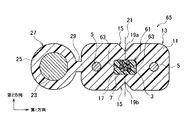
図6を併せて参照するに、光ファイバ3とUV樹脂7とからなる光ファイバユニット53は、前記長手方向に垂直な面内において楕円形状の断面であり、光ファイバユニット53の光ファイバ3の分離性を良くするために第2ノッチ部としての例えばノッチ部55が楕円形状のUV樹脂7の外周面に対向する位置に2つ設けられている。なお、上記のノッチ部55は予め設けられており、押出成形時は、光ファイバユニット53が図4のパイプ45内を通過するので、ノッチ部55が空隙として形成されるものである。なお、上記の光ファイバユニット53では2つのノッチ部55を有しているが、UV樹脂7の外周面に少なくとも1箇所を有していればよい。   Referring also to FIG. 6, the optical fiber unit 53 composed of the optical fiber 3 and the UV resin 7 has an elliptical cross section in a plane perpendicular to the longitudinal direction, and the optical fiber 3 of the optical fiber unit 53 In order to improve the separability, for example, two notch portions 55 as the second notch portions are provided at positions facing the outer peripheral surface of the elliptical UV resin 7. The notch portion 55 is provided in advance, and the optical fiber unit 53 passes through the pipe 45 shown in FIG. 4 during extrusion, so that the notch portion 55 is formed as a gap. The optical fiber unit 53 has two notches 55, but it is sufficient that at least one location is provided on the outer peripheral surface of the UV resin 7.

さらに、第2の実施の形態の光ファイバユニット53では、2つのノッチ部55を結ぶ線と、ケーブルシース11の2つのノッチ部15を結ぶ線21が一致するように形成されている。この場合は、ケーブルシース11を引裂く時に、光ファイバユニット53も同時に引裂かれる可能性を有する。仮に、同時に切り裂くことができなくても、後で、光ファイバユニット53のノッチ部55を基点に引裂けば良いものであり、光ファイバ3の分離性が向上する。   Furthermore, in the optical fiber unit 53 of the second embodiment, the line connecting the two notches 55 and the line 21 connecting the two notches 15 of the cable sheath 11 are formed to coincide. In this case, when the cable sheath 11 is torn, the optical fiber unit 53 may be torn at the same time. Even if they cannot be cut simultaneously, they can be torn later with the notch portion 55 of the optical fiber unit 53 as a base point, and the separability of the optical fiber 3 is improved.

図7を参照するに、第2の実施の形態の光ファイバケーブル51の変形例の光ファイバケーブル57としては、光ファイバユニット53の2つのノッチ部55を結ぶ線が、ケーブルシース11の2つのノッチ部15を結ぶ線21に対して直交する方向に配置されている。他は図6と同様である。   Referring to FIG. 7, as an optical fiber cable 57 of a modified example of the optical fiber cable 51 of the second embodiment, a line connecting the two notches 55 of the optical fiber unit 53 includes two lines of the cable sheath 11. They are arranged in a direction perpendicular to the line 21 connecting the notches 15. Others are the same as FIG.

この場合は、光ファイバケーブル57のケーブルシース11を引裂く時に、光ファイバユニット53が同時に引裂かれることはない。光ファイバユニット53が取り出された後に、光ファイバユニット53のノッチ部55を基点に容易に引裂かれて、光ファイバ3がUV樹脂7から容易に分離される。   In this case, when the cable sheath 11 of the optical fiber cable 57 is torn, the optical fiber unit 53 is not torn simultaneously. After the optical fiber unit 53 is taken out, the optical fiber 3 is easily separated from the UV resin 7 by being easily torn with the notch 55 of the optical fiber unit 53 as a base point.

次に、この発明の第4の実施の形態の光ファイバケーブル59について図面を参照して説明する。前述した第1の実施の形態の光ファイバケーブル1で説明した図2とほぼ同様の構造であって、光ファイバユニット9の構成が異なり、他は同じであるので、異なる点を説明し、他の同部材は同符号を付すと共に説明は省略する。また、第1の実施の形態で説明した図1と同様の構造のインドア型の光ケーブルは光ファイバケーブル59と同様であるので、説明は省略する。   Next, an optical fiber cable 59 according to a fourth embodiment of the present invention will be described with reference to the drawings. The structure is almost the same as that of FIG. 2 described in the optical fiber cable 1 of the first embodiment described above, and the configuration of the optical fiber unit 9 is different, and the others are the same. The same members are denoted by the same reference numerals and description thereof is omitted. Further, the indoor type optical cable having the same structure as that of FIG. 1 described in the first embodiment is the same as the optical fiber cable 59, and thus the description thereof is omitted.

図8を併せて参照するに、光ファイバ3とUV樹脂7とからなる光ファイバユニット53は、前記長手方向に垂直な面内において矩形状の断面(ここでは長方形)であり、光ファイバユニット61の光ファイバ3の分離性を良くするために第2ノッチ部としての例えばノッチ部63が矩形状のUV樹脂7の外周面に2つ設けられている。なお、上記のノッチ部63は予め設けられており、押出成形時は、光ファイバユニット61が図4のパイプ45内を通過するので、ノッチ部63が空隙として形成されるものである。なお、上記の光ファイバユニット61では2つのノッチ部63を有しているが、UV樹脂7の外周面に少なくとも1箇所を有していればよい。   Referring also to FIG. 8, the optical fiber unit 53 composed of the optical fiber 3 and the UV resin 7 has a rectangular cross section (in this case, a rectangle) in a plane perpendicular to the longitudinal direction, and the optical fiber unit 61. For example, two notches 63 as second notches are provided on the outer peripheral surface of the rectangular UV resin 7 in order to improve the separation of the optical fiber 3. The notch 63 is provided in advance, and the notch 63 is formed as a gap because the optical fiber unit 61 passes through the pipe 45 in FIG. 4 during extrusion molding. The optical fiber unit 61 has two notches 63, but it is sufficient that at least one location is provided on the outer peripheral surface of the UV resin 7.

さらに、第4の実施の形態の光ファイバユニット61では、2つのノッチ部63を結ぶ線と、ケーブルシース11の2つのノッチ部15を結ぶ線21が一致するように形成されている。この場合は、ケーブルシース11を引裂く時に、光ファイバユニット61も同時に引裂かれる可能性を有する。仮に、同時に切り裂くことができなくても、後で、光ファイバユニット61のノッチ部63を基点に引裂けば良いものであり、光ファイバ3の分離性が向上する。   Furthermore, in the optical fiber unit 61 of the fourth embodiment, the line connecting the two notches 63 and the line 21 connecting the two notches 15 of the cable sheath 11 are formed to coincide. In this case, when the cable sheath 11 is torn, the optical fiber unit 61 may be torn at the same time. Even if they cannot be cut at the same time, they can be torn later with the notch 63 of the optical fiber unit 61 as a base point, and the separability of the optical fiber 3 is improved.

図9を参照するに、第4の実施の形態の光ファイバケーブル59の変形例の光ファイバケーブル65としては、光ファイバユニット61の2つのノッチ部63を結ぶ線が、ケーブルシース11の2つのノッチ部15を結ぶ線21に対して直交する方向に配置されている。他は図8と同様である。   Referring to FIG. 9, as an optical fiber cable 65 of a modification of the optical fiber cable 59 of the fourth embodiment, a line connecting two notches 63 of the optical fiber unit 61 includes two lines of the cable sheath 11. They are arranged in a direction perpendicular to the line 21 connecting the notches 15. Others are the same as FIG.

この場合は、光ファイバユニット61のケーブルシース11を引裂く時に、光ファイバユニット61が同時に引裂かれることはない。光ファイバユニット61が取り出された後に、光ファイバユニット61のノッチ部63を基点に容易に引裂かれて、光ファイバ3がUV樹脂7から容易に分離される。   In this case, when the cable sheath 11 of the optical fiber unit 61 is torn, the optical fiber unit 61 is not torn simultaneously. After the optical fiber unit 61 is taken out, the optical fiber 3 is easily separated from the UV resin 7 by being easily torn with the notch 63 of the optical fiber unit 61 as a base point.

なお、前述した第3、第4の実施の形態の光ファイバケーブルのいずれにおいても、UV樹脂7のヤング率が十分小さい場合は、図1の第1の実施の形態と同様に光ファイバユニットのノッチ部が存在しない形状であっても切り裂き可能である。また、光ファイバユニット9,53,61のUV樹脂7の断面形状は、前述した実施の形態で示した円形、楕円形、矩形に限定されるものではなく、他の形状であっても構わない。   In any of the optical fiber cables of the third and fourth embodiments described above, when the Young's modulus of the UV resin 7 is sufficiently small, the optical fiber unit of the optical fiber unit is the same as in the first embodiment of FIG. Even if the shape has no notch, it can be torn. Further, the cross-sectional shape of the UV resin 7 of the optical fiber units 9, 53, 61 is not limited to the circular shape, the elliptical shape, and the rectangular shape shown in the above-described embodiment, and may be other shapes. .

この発明の第1の実施の形態の光ファイバケーブルの断面図である。It is sectional drawing of the optical fiber cable of 1st Embodiment of this invention. この発明の第2の実施の形態の光ファイバケーブルの断面図である。It is sectional drawing of the optical fiber cable of 2nd Embodiment of this invention. 押出ヘッド部の断面図である。It is sectional drawing of an extrusion head part. ニップル部の斜視図である。It is a perspective view of a nipple part. ダイス部の斜視図である。It is a perspective view of a die part. この発明の第3の実施の形態の光ファイバケーブルの断面図である。It is sectional drawing of the optical fiber cable of the 3rd Embodiment of this invention. この発明の第3の実施の形態の変形例を示す光ファイバケーブルの断面図である。It is sectional drawing of the optical fiber cable which shows the modification of the 3rd Embodiment of this invention. この発明の第4の実施の形態の光ファイバケーブルの断面図である。It is sectional drawing of the optical fiber cable of 4th Embodiment of this invention. この発明の第4の実施の形態の変形例を示す光ファイバケーブルの断面図である。It is sectional drawing of the optical fiber cable which shows the modification of 4th Embodiment of this invention. 従来の光ファイバケーブルの断面図である。It is sectional drawing of the conventional optical fiber cable. 従来の別の光ファイバケーブルの断面図である。It is sectional drawing of another conventional optical fiber cable. 従来の光ファイバケーブルをデタッチャーで切り裂くときの状態説明図である。It is state explanatory drawing when a conventional optical fiber cable is cut with a detacher. 図12に続く工程で、デタッチャーで切り裂くときの状態説明図である。FIG. 13 is a state explanatory diagram when cutting with a detacher in the process following FIG. 12. 図13に続く工程で、デタッチャーで切り裂くときの状態説明図である。FIG. 14 is a state explanatory diagram when cutting with a detacher in the process following FIG. 13.

符号の説明Explanation of symbols

1 光ファイバケーブル(第1,第2の実施の形態の)
3 光ファイバ
5 光エレメント用抗張力体
7 紫外線硬化型樹脂(UV樹脂)
9 光ファイバユニット
11 ケーブルシース
13 光エレメント部
15 ノッチ部
17 中空部
19a、19b ノッチ部15の頂点
21 面(直線)
23 支持線
25 シース
27 ケーブル支持線部
29 首部
51 光ファイバケーブル(第3の実施の形態の)
53 光ファイバユニット
55 ノッチ部(第2ノッチ部)
57 光ファイバケーブル(第3の実施の形態の変形例)
59 光ファイバケーブル(第4の実施の形態の)
61 光ファイバユニット
63 ノッチ部(第2ノッチ部)
65 光ファイバケーブル(第4の実施の形態の変形例)
1 Optical fiber cable (of the first and second embodiments)
3 Optical fiber 5 Strength element for optical element 7 UV curable resin (UV resin)
DESCRIPTION OF SYMBOLS 9 Optical fiber unit 11 Cable sheath 13 Optical element part 15 Notch part 17 Hollow part 19a, 19b The vertex 21 surface (straight line) of the notch part 15
23 Support line 25 Sheath 27 Cable support line part 29 Neck part 51 Optical fiber cable (in the third embodiment)
53 Optical fiber unit 55 Notch (second notch)
57 Optical fiber cable (modified example of the third embodiment)
59 Optical fiber cable (of the fourth embodiment)
61 Optical fiber unit 63 Notch (second notch)
65 Optical fiber cable (modified example of the fourth embodiment)

Claims (7)

光ファイバと、
この光ファイバの周囲に紫外線硬化型樹脂を被覆して一束化した光ファイバユニットと、
この光ファイバユニットの長手方向に沿って光ファイバユニットの両側に配置された抗張力体と、
前記光ファイバユニット、及び抗張力体を被覆するケーブルシースであって、前記長手方向に垂直な面内において前記抗張力体を結ぶ第1方向に直交する第2方向の前記光ファイバユニットの外側におけるケーブルシースの表面にノッチ部が形成されたケーブルシースと、
を備える長尺の光エレメント部を有することを特徴とする光ファイバケーブル。
Optical fiber,
An optical fiber unit in which an ultraviolet curable resin is coated around the optical fiber and bundled,
Strength members disposed on both sides of the optical fiber unit along the longitudinal direction of the optical fiber unit,
A cable sheath covering the optical fiber unit and a tensile body, and a cable sheath outside the optical fiber unit in a second direction orthogonal to a first direction connecting the tensile bodies in a plane perpendicular to the longitudinal direction. A cable sheath having a notch portion formed on the surface thereof,
An optical fiber cable comprising a long optical element portion comprising:
前記光ファイバユニットの紫外線硬化型樹脂は、当該紫外線硬化型樹脂の硬化後のヤング率が1MPaを超え、且つ100MPa未満に構成してなることを特徴とする請求項1記載の光ファイバケーブル。   2. The optical fiber cable according to claim 1, wherein the ultraviolet curable resin of the optical fiber unit is configured to have a Young's modulus after curing of the ultraviolet curable resin of more than 1 MPa and less than 100 MPa. 前記光ファイバユニットが、前記長手方向に垂直な面内において紫外線硬化型樹脂の外周面に少なくとも1箇所の第2ノッチ部を有してなることを特徴とする請求項1又は2記載の光ファイバケーブル。   3. The optical fiber according to claim 1, wherein the optical fiber unit has at least one second notch portion on the outer peripheral surface of the ultraviolet curable resin in a plane perpendicular to the longitudinal direction. cable. 前記光ファイバユニットが、2つの第2ノッチ部を有すると共に、前記2つの第2ノッチ部を結ぶ線を第2方向に向けて配置してなることを特徴とする請求項3記載の光ファイバケーブル。   4. The optical fiber cable according to claim 3, wherein the optical fiber unit has two second notch portions, and a line connecting the two second notch portions is arranged in the second direction. . 前記光ファイバユニットが、2つの第2ノッチ部を有すると共に、前記2つの第2ノッチ部を結ぶ線を第1方向に向けて配置してなることを特徴とする請求項3記載の光ファイバケーブル。   4. The optical fiber cable according to claim 3, wherein the optical fiber unit has two second notch portions and a line connecting the two second notch portions is arranged in the first direction. . 支持線をシースで被覆した長尺のケーブル支持線部であって、前記光エレメント部に平行に配置され且つ一体化されたケーブル支持線部を有することを特徴とする請求項1〜5のうちの何れかに記載の光ファイバケーブル。   6. A long cable support line part in which a support line is covered with a sheath, wherein the cable support line part is arranged in parallel with and integrated with the optical element part. An optical fiber cable according to any one of the above. 前記光ファイバは、単数または複数の素線または心線を有することを特徴とする請求項1〜6のうちの何れかに記載の光ファイバケーブル。   The optical fiber cable according to any one of claims 1 to 6, wherein the optical fiber has one or more strands or cores.
JP2004106182A 2004-03-31 2004-03-31 Fiber-optic cable Pending JP2005292400A (en)

Priority Applications (1)

Application Number Priority Date Filing Date Title
JP2004106182A JP2005292400A (en) 2004-03-31 2004-03-31 Fiber-optic cable

Applications Claiming Priority (1)

Application Number Priority Date Filing Date Title
JP2004106182A JP2005292400A (en) 2004-03-31 2004-03-31 Fiber-optic cable

Publications (1)

Publication Number Publication Date
JP2005292400A true JP2005292400A (en) 2005-10-20

Family

ID=35325397

Family Applications (1)

Application Number Title Priority Date Filing Date
JP2004106182A Pending JP2005292400A (en) 2004-03-31 2004-03-31 Fiber-optic cable

Country Status (1)

Country Link
JP (1) JP2005292400A (en)

Cited By (4)

* Cited by examiner, † Cited by third party
Publication number Priority date Publication date Assignee Title
JP2007115636A (en) * 2005-10-24 2007-05-10 Fujikura Ltd Communication cable
JP2009217081A (en) * 2008-03-12 2009-09-24 Furukawa Electric Co Ltd:The Optical fiber cable
JP2010039049A (en) * 2008-08-01 2010-02-18 Fujikura Ltd Optical fiber cable
JP2011232711A (en) * 2010-04-30 2011-11-17 Sumitomo Electric Ind Ltd Multi-core optical fiber and method for separating multi-core optical fiber into single-core optical fibers

Cited By (5)

* Cited by examiner, † Cited by third party
Publication number Priority date Publication date Assignee Title
JP2007115636A (en) * 2005-10-24 2007-05-10 Fujikura Ltd Communication cable
JP2009217081A (en) * 2008-03-12 2009-09-24 Furukawa Electric Co Ltd:The Optical fiber cable
JP2010039049A (en) * 2008-08-01 2010-02-18 Fujikura Ltd Optical fiber cable
JP2011232711A (en) * 2010-04-30 2011-11-17 Sumitomo Electric Ind Ltd Multi-core optical fiber and method for separating multi-core optical fiber into single-core optical fibers
US8811788B2 (en) 2010-04-30 2014-08-19 Sumitomo Electric Industries, Ltd. Multi-core optical fiber and method of producing the same

Similar Documents

Publication Publication Date Title
JP5121211B2 (en) Optical fiber distribution cable and structure thereof
JP4547367B2 (en) Manufacturing method of optical fiber wiring cable
US5649042A (en) Pre-connectorized loose tube cable
JP4252991B2 (en) Optical fiber cable, optical fiber extraction method, and optical fiber extraction tool
JP2007304550A (en) Method for manufacturing fiber optic distribution cable
US20150153529A1 (en) Optical fiber cables with polyethylene binder
JP2017097089A (en) Optical fiber cable
JP2005292400A (en) Fiber-optic cable
JP2005308916A (en) Optical fiber cable
EP3067726A1 (en) Fiber optic distribution cables and structures therefor
US20160103288A1 (en) Optical fiber cables with polypropylene binder
JP2007304552A (en) Parts kit for manufacturing fiber optic distribution cable
JP2005128423A (en) Optical fiber cable and its manufacturing method
JP4665048B1 (en) Optical drop cable
JP2006323165A (en) Optical fiber cable
JPH10148737A (en) Aerial outdoor optical cable
JP3662824B2 (en) Fiber optic cable
JP2005091616A (en) Optical fiber cable and method for manufacturing the same
JP2009075333A (en) Optical cable unit, assembly optical cable, and detecting method of optical cable unit
JP4878888B2 (en) Optical fiber cable and lead-out method thereof
JP4714302B2 (en) Optical drop cable
JP4059825B2 (en) Optical drop cable
JP2006317860A (en) Optical fiber drop cable
JP2006003689A (en) Optical drop cable
JP3993162B2 (en) Fiber optic cable