JP2005292372A - Image forming apparatus - Google Patents
Image forming apparatus Download PDFInfo
- Publication number
- JP2005292372A JP2005292372A JP2004105746A JP2004105746A JP2005292372A JP 2005292372 A JP2005292372 A JP 2005292372A JP 2004105746 A JP2004105746 A JP 2004105746A JP 2004105746 A JP2004105746 A JP 2004105746A JP 2005292372 A JP2005292372 A JP 2005292372A
- Authority
- JP
- Japan
- Prior art keywords
- power supply
- operation panel
- operation mode
- image forming
- forming apparatus
- Prior art date
- Legal status (The legal status is an assumption and is not a legal conclusion. Google has not performed a legal analysis and makes no representation as to the accuracy of the status listed.)
- Pending
Links
Images


Classifications
-
- Y—GENERAL TAGGING OF NEW TECHNOLOGICAL DEVELOPMENTS; GENERAL TAGGING OF CROSS-SECTIONAL TECHNOLOGIES SPANNING OVER SEVERAL SECTIONS OF THE IPC; TECHNICAL SUBJECTS COVERED BY FORMER USPC CROSS-REFERENCE ART COLLECTIONS [XRACs] AND DIGESTS
- Y02—TECHNOLOGIES OR APPLICATIONS FOR MITIGATION OR ADAPTATION AGAINST CLIMATE CHANGE
- Y02D—CLIMATE CHANGE MITIGATION TECHNOLOGIES IN INFORMATION AND COMMUNICATION TECHNOLOGIES [ICT], I.E. INFORMATION AND COMMUNICATION TECHNOLOGIES AIMING AT THE REDUCTION OF THEIR OWN ENERGY USE
- Y02D10/00—Energy efficient computing, e.g. low power processors, power management or thermal management
Landscapes
- Accessory Devices And Overall Control Thereof (AREA)
- Control Or Security For Electrophotography (AREA)
Abstract
Description
この発明は、入力された画像データに基づいて画像形成処理を行う画像形成装置に関し、特に、通常動作モードと省電力動作モードとが切り換えられる画像形成装置に関する。 The present invention relates to an image forming apparatus that performs image forming processing based on input image data, and more particularly to an image forming apparatus that can be switched between a normal operation mode and a power saving operation mode.
省電力化の要請により、通常動作モードまたは省電力動作モードを適宜切り換えて動作する画像形成装置が増えている。このような画像形成装置では、通常動作モード時に一定時間以上ジョブの指示がされない場合に省電力動作モードに移行し、省電力動作モード時に印刷開始キー等の所定キーが押されると通常動作モードに復帰するように制御されるものが多い。 Due to the demand for power saving, an increasing number of image forming apparatuses operate by appropriately switching between the normal operation mode and the power saving operation mode. In such an image forming apparatus, when a job is not instructed for a certain period of time in the normal operation mode, the image forming apparatus shifts to the power saving operation mode. When a predetermined key such as a print start key is pressed in the power saving operation mode, the image forming apparatus enters the normal operation mode. Many are controlled to return.
省電力化をための技術の例として、従来、省電力動作時にキーマトリクス中のいずれかのキーに対するキー操作を受けてMPUを起動させ、その後のキースキャンを可能にする技術があった(例えば、特許文献1参照。)。 As an example of a technology for power saving, there has been a technology that activates an MPU upon receiving a key operation on any key in a key matrix during a power saving operation and enables subsequent key scanning (for example, , See Patent Document 1).
また、他の従来技術として、ラダー抵抗の接続点にキースイッチを配置し、ラダー抵抗の分圧比を変えてA/Dコンバータに入力するとともにコンパレータで監視し、このコンパレータ出力を通常動作モードに復帰するためのトリガとする技術があった(例えば、特許文献2参照。)。 As another conventional technology, a key switch is arranged at the connection point of the ladder resistor, the voltage dividing ratio of the ladder resistor is changed and input to the A / D converter and monitored by the comparator, and the comparator output is returned to the normal operation mode. There has been a technique for setting a trigger to do this (see, for example, Patent Document 2).
これらの従来技術では、キーマトリクスに対するキー操作に基づいて、省電力動作モードの解除を行うことができる、とされている。
しかしながら、上述の特許文献1および特許文献2を含む従来技術では、省電力動作モードから通常動作モードに復帰するためのトリガとなる行為がキー操作だけに限定されている。
However, in the related arts including
通常動作モードに復帰するためのトリガとなる行為がキー操作だけに限定される場合、ユーザが操作パネルにおける操作キー以外の箇所に触れても省電力動作モードが解除されない。このため、ユーザが操作パネルの前で画像形成処理の準備が整っているにもかかわらず、操作ミスによって省電力動作モードの解除が遅れることがある。 When the act as a trigger for returning to the normal operation mode is limited to only the key operation, the power saving operation mode is not canceled even if the user touches a portion other than the operation key on the operation panel. For this reason, although the user is ready for the image forming process in front of the operation panel, the cancellation of the power saving operation mode may be delayed due to an operation error.
この発明の目的は、操作ミスによって省電力動作モードの解除が遅れるという不都合が生じにくい画像形成装置を提供することである。 An object of the present invention is to provide an image forming apparatus that is less likely to cause a disadvantage that the release of the power saving operation mode is delayed due to an operation error.
この発明は以下の構成を備えている。 The present invention has the following configuration.
(1)装置の動作状態に応じて装置の動作モードを、主電源部を動作させる通常動作モードまたは主電源部を停止させて補助電源部のみを動作させる省電力動作モードのいずれかに切り換える電源制御部と、
ユーザからの入力操作を受け付ける操作パネルと、を備えた画像形成装置であって、
前記操作パネルに加えられた押圧力を検出する検出手段を有し、
省電力動作モード時に前記前記検出手段が前記押圧力を検出すると、前記電源制御部が前記主電源部を動作させることを特徴とする。
(1) A power supply that switches the operation mode of the device to either a normal operation mode in which the main power supply unit is operated or a power saving operation mode in which only the auxiliary power supply unit is operated by stopping the main power supply unit according to the operation state of the device A control unit;
An operation panel for receiving an input operation from a user,
Detecting means for detecting a pressing force applied to the operation panel;
The power supply control unit operates the main power supply unit when the detection unit detects the pressing force in the power saving operation mode.
本発明に係る画像形成装置は、電源制御部、操作パネル、および検出手段を備えている。電源制御部は、装置の動作状態に応じて画像形成装置を通常動作モードまたは省電力動作モードのいずれかに切り換える。操作パネルは、ジョブの入力等を含むユーザからの入力操作を受け付ける。検出手段は、操作パネルに加えられた押圧力を検出する。 An image forming apparatus according to the present invention includes a power control unit, an operation panel, and a detection unit. The power control unit switches the image forming apparatus to either the normal operation mode or the power saving operation mode according to the operation state of the apparatus. The operation panel accepts input operations from the user including job input and the like. The detection means detects the pressing force applied to the operation panel.
省電力動作モード時に操作パネルに加えられた押圧力を検出手段が検出すると、電源制御部が省電力動作モードを解除する。なお、省電力動作モード時において電源制御部は補助電源部から給電される。 When the detection means detects the pressing force applied to the operation panel in the power saving operation mode, the power control unit cancels the power saving operation mode. In the power saving operation mode, the power supply control unit is supplied with power from the auxiliary power supply unit.
例えば、省電力動作モード時に、ユーザが操作パネルに対して力を加えると画像形成装置が通常動作モードに復帰する。ユーザは、省電力動作モードを解除したい場合には、操作パネルに触れるだけで良く、特別な操作を行う必要はない。ユーザは画像形成装置を操作する際、必然的に操作パネルに触れる。このため、操作パネルに加えられる押圧力を省電力動作モードの解除用トリガとしておけば、画像形成装置に対する操作体勢が整ったにもかかわらず省電力動作モードが解除されないという不都合が発生しにくくなる。 For example, when the user applies a force to the operation panel in the power saving operation mode, the image forming apparatus returns to the normal operation mode. When the user wants to cancel the power saving operation mode, the user only has to touch the operation panel and does not need to perform a special operation. The user inevitably touches the operation panel when operating the image forming apparatus. For this reason, if the pressing force applied to the operation panel is used as a trigger for canceling the power saving operation mode, the inconvenience that the power saving operation mode is not canceled even though the operation posture for the image forming apparatus is ready. .
(2)前記操作パネルは、前記押圧力に係る押圧方向において移動自在にされており、
前記検出手段は、前記操作パネルの移動に伴って開放または閉成するスイッチを有することを特徴とする。
(2) The operation panel is movable in a pressing direction related to the pressing force,
The detection means has a switch that opens or closes as the operation panel moves.
この構成においては、操作パネルが押圧力の作用に伴って移動するように構成されている。操作パネルを移動自在にするための構成例として、操作パネルの端部に弾性部材を固定し、この弾性部材を介して操作パネルを画像形成装置に接続する構成が挙げられる。この弾性部材は、操作パネルと画像形成装置本体の取付位置との間に空間を形成するスペーサとして機能するため、弾性部材が伸縮する範囲において操作パネルが移動自在になる。 In this configuration, the operation panel is configured to move with the action of the pressing force. As a configuration example for making the operation panel movable, there is a configuration in which an elastic member is fixed to an end portion of the operation panel, and the operation panel is connected to the image forming apparatus via the elastic member. Since this elastic member functions as a spacer that forms a space between the operation panel and the mounting position of the image forming apparatus main body, the operation panel can be moved within a range in which the elastic member expands and contracts.
さらに、操作パネルに押圧力が加わって操作パネルが変位することにより、接点の状態が変化するスイッチを検出手段が含んでいる。このようなスイッチを使用することで、操作パネルに加えられた押圧力を検出するのに高度なアクチュエータ等が必要になることがない。 Further, the detecting means includes a switch that changes a contact state when the operation panel is displaced by applying a pressing force to the operation panel. By using such a switch, an advanced actuator or the like is not required to detect the pressing force applied to the operation panel.
(3)前記操作パネルは平面視略長方形を呈しており、前記検出手段が前記操作パネルの長手方向の両端部に当接するように配置されることを特徴とする。 (3) The operation panel has a substantially rectangular shape in plan view, and the detection means is disposed so as to abut on both ends in the longitudinal direction of the operation panel.
この構成においては、操作パネルに加えられた押圧力を検出するための検出手段が操作パネルの長手方向の両端部に対応する位置に配置される。この位置に検出手段を配置するのは、操作パネルの端部に加えられた押圧力の検出ミスを発生しにくくするためである。長方形状の操作パネルの場合、検出手段の配置位置と長手方向の反対側に作用する力を検出しにくい。本発明では、長手方向の両端部に検出手段を配置することにより、操作パネルのどの位置に押圧力が作用しても、その押圧力を検出し易くなる。 In this configuration, detection means for detecting the pressing force applied to the operation panel is disposed at positions corresponding to both ends in the longitudinal direction of the operation panel. The reason why the detecting means is arranged at this position is to make it difficult to generate a detection error of the pressing force applied to the end of the operation panel. In the case of a rectangular operation panel, it is difficult to detect a force acting on the opposite side of the longitudinal position of the detection means. In the present invention, by disposing detection means at both ends in the longitudinal direction, it becomes easy to detect the pressing force regardless of the position on the operation panel.
(4)前記検出手段は、前記操作パネルに加えられた押圧力によってオンになるスイッチであり、
前記電源制御部は、省電力動作モード時に前記補助電源部から給電され、省電力動作モードから通常動作モードへの復帰時に前記主電源部の起動信号入力端子に所定電位の起動信号を入力し、
前記起動信号入力端子は、前記スイッチを介して所定電位に接続されることを特徴とする。
(4) The detection means is a switch that is turned on by a pressing force applied to the operation panel,
The power supply control unit is fed from the auxiliary power supply unit during the power saving operation mode, and inputs a start signal having a predetermined potential to the start signal input terminal of the main power supply unit when returning from the power saving operation mode to the normal operation mode.
The activation signal input terminal is connected to a predetermined potential through the switch.
この構成においては、操作パネルに加えられた力によりスイッチがオンになり、このスイッチを介して電源制御部から主電力部に起動信号が入力される。なお、省電力動作モード時に補助電源部から電源制御部に供給されるべき電力量として、スイッチがオンになったときに起動信号入力端子を所定電位にするだけの量があれば良い。 In this configuration, the switch is turned on by a force applied to the operation panel, and an activation signal is input from the power supply control unit to the main power unit via the switch. It should be noted that the amount of power to be supplied from the auxiliary power supply unit to the power supply control unit in the power saving operation mode may be an amount sufficient to bring the activation signal input terminal to a predetermined potential when the switch is turned on.
(5)前記操作パネルにおける各キーは、ユーザの入力操作によって開放状態から閉成状態になる接点をさらに含んでおり、
前記接点を構成する第1の端子が所定電位に接続され、第2の端子が前記起動信号入力端子に接続されることを特徴とする。
(5) Each key on the operation panel further includes a contact that is changed from an open state to a closed state by a user input operation,
A first terminal constituting the contact is connected to a predetermined potential, and a second terminal is connected to the activation signal input terminal.
この構成においては、入力操作の内容を特定するための接点と、省電力動作モードを解除するトリガとなるキー操作を検出するための接点とが、1つのキートップを押圧することにより閉成状態になる。このため、従来の操作パネルにも省電力動作モードを解除するトリガを検出する構成を追加することが可能になる。 In this configuration, the contact for specifying the content of the input operation and the contact for detecting the key operation that triggers the cancellation of the power saving operation mode are closed by pressing one key top. become. For this reason, it becomes possible to add the structure which detects the trigger which cancels | releases a power saving operation mode also to the conventional operation panel.
このように省電力動作モードを解除するトリガとなるキー操作を検出するための接点を追加する理由は、ユーザが操作キーに軽く触れた場合に、検出手段が検出できる程度に十分な押圧力が操作パネルに作用しないことがあるからである。 The reason for adding a contact for detecting a key operation as a trigger for canceling the power saving operation mode in this way is that when the user touches the operation key lightly, a pressing force sufficient to detect the detection means is provided. This is because it may not act on the operation panel.
(6)前記操作パネルは、ユーザの入力操作によって開放状態から閉成状態になる接点を含むアナログ抵抗膜方式のタッチパネルであり、
前記接点を構成する第1の導電膜が所定電位に接続され、第2の導電膜が前記起動信号入力端子に接続され、かつ、前記第1の導電膜および前記第2の導電膜に対し入力操作に係る押圧位置を特定するための電位勾配が前記主電源部を介して与えられることを特徴とする。
(6) The operation panel is an analog resistive film type touch panel including a contact that is changed from an open state to a closed state by a user input operation,
The first conductive film constituting the contact is connected to a predetermined potential, the second conductive film is connected to the activation signal input terminal, and input to the first conductive film and the second conductive film A potential gradient for specifying a pressed position related to the operation is given through the main power supply unit.
この構成においては、操作パネルに対するユーザの操作によって、タッチパネルに含まれる第1の導電膜と第2の導電膜とが接触し、この接触により省電力動作モードを解除するための信号が生成される。 In this configuration, the first conductive film and the second conductive film included in the touch panel come into contact with each other by a user operation on the operation panel, and a signal for canceling the power saving operation mode is generated by the contact. .
通常動作モード時には主電源部からの給電によりタッチパネルに対する操作内容の検出が行われる。省電力動作モード時には主電源部が停止し、補助電源部からの給電によりタッチパネルに対するユーザのキー操作の有無が検出される。 In the normal operation mode, the operation content for the touch panel is detected by the power supply from the main power supply unit. In the power saving operation mode, the main power supply unit is stopped, and the presence or absence of a user key operation on the touch panel is detected by power supply from the auxiliary power supply unit.
この発明によれば、以下の効果を奏することができる。 According to the present invention, the following effects can be obtained.
(1)操作ミスによって省電力動作モードの解除が遅れるという不都合を生じにくくすることができる。 (1) The inconvenience that the cancellation of the power saving operation mode is delayed due to an operation error can be made difficult to occur.
(2)複雑な構成を用いることなく、操作パネルに加えられた押圧力を検出することができる。 (2) The pressing force applied to the operation panel can be detected without using a complicated configuration.
(3)操作パネルにおける押圧力の作用位置にかかわらず、押圧力の検出ミスの発生を抑えることができる。 (3) Regardless of the position where the pressing force is applied on the operation panel, occurrence of a pressing force detection error can be suppressed.
(4)省電力動作モード時における電力消費を抑えることができる。 (4) Power consumption in the power saving operation mode can be suppressed.
(5)操作キーに加えられた小さい力を検出して省電力動作モードの解除を行うことができる。 (5) The power saving operation mode can be canceled by detecting a small force applied to the operation key.
(6)タッチパネルに触れたことを検出して省電力動作モードの解除を行うことができる。省電力動作モード時における電位勾配による電力消費をなくすことができる。 (6) The touch of the touch panel can be detected to cancel the power saving operation mode. It is possible to eliminate power consumption due to a potential gradient in the power saving operation mode.
以下、図を用いて本発明の画像形成装置の実施形態であるディジタル複写機を説明する。 A digital copying machine as an embodiment of the image forming apparatus of the present invention will be described below with reference to the drawings.
図1は、第1の実施形態に係るディジタル複写機1の概略構成を示す。同図に示すように、ディジタル複写機1は、原稿読取部110、画像形成部210、多段給紙デスク300、および後処理装置260を備えている。
FIG. 1 shows a schematic configuration of a digital copying
原稿読取部110は、透明ガラスからなる原稿台111、原稿読取部110の上方に配置される自動原稿搬送装置112、および原稿台111に載置された原稿の画像を読み取る光学系ユニットを備えている。
The
自動原稿搬送装置112は、原稿セットトレイ上にセットされた複数枚の原稿を1枚ずつ自動的に原稿台111上へ給送する装置である。また、自動原稿搬送装置112は、原稿カバーとしても機能する。
The
自動原稿搬送装置112には、ジョブの入力や画像形成内容の設定等のユーザから入力操作を受け付ける操作パネル40が配置される。本発明は、この操作パネル40に加えられる力をディジタル複写機1の動作状態の切換に利用する点に特徴を有するものであり、その詳細は後述する。
The
光学系ユニットは、原稿台111の下方に配置され、原稿台111上に載置された原稿の画像を走査して読み取る。この光学系ユニットは、第1の走査ユニット113、第2の走査ユニット114、光学レンズ115、および光電変換素子であるCCDラインセンサ116を有している。
The optical system unit is disposed below the document table 111 and scans and reads an image of the document placed on the document table 111. The optical system unit includes a
第1の走査ユニット113は、原稿面上を露光する露光ランプユニット、原稿からの反射光像を所定の方向に反射させる第1ミラーを備えている。第2の走査ユニット114は、第1ミラーから反射されてくる原稿からの反射光をCCDラインセンサ116に導く第2ミラーおよび第3ミラーを備えている。光学レンズ115は、原稿からの反射光をCCDラインセンサ116上に結像させる。CCDラインセンサ116は、原稿からの反射光を光電変換して画像データを生成する。なお、この画像データは、図示しない画像処理部を介して、画像形成部210に出力される。
The
画像形成部210の下部には、手差しトレイ254、用紙カセット251,252,253、および両面ユニット255が備えられている。手差しトレイ254、用紙カセット251,252,253、および両面ユニット255によって給紙部300が構成される。
A
用紙カセット251〜253、および手差しトレイ254のそれぞれから、画像形成位置を経由して後処理装置260までの間に用紙搬送路が形成される。また、用紙カセット251〜253、または手差しトレイ254や両面ユニット255から給紙された用紙は搬送ローラを有する搬送ユニット250を介して画像形成部210に供給される。
A sheet conveyance path is formed from each of the
両面ユニット255は、用紙を反転させるスイッチバック路221に通じており、用紙の両面に画像形成を行う時に用いられる。なお、両面ユニット255は通常の用紙カセットと交換可能な構成となっており、両面ユニット255を通常の用紙カセットに置き換えて構成しても良い。
The
画像形成部210は、用紙搬送路に沿って上流側から順番に画像形成ユニット、定着ユニット217、および排紙ローラ219を備えている。画像形成ユニットは、像担持体としての感光体ドラム222、露光装置としての光書込装置227、感光体ドラム222を所定の電位に帯電させる帯電器223、感光体ドラム222上に形成された静電潜像にトナーを供給して顕像化する現像器224、感光体ドラム222表面に形成されたトナー像を用紙に転写するチャージャ方式の転写器225、用紙を除電し像担持体222から剥離し易くする除電器229、余分なトナーを回収するクリーニング器226を備えている。
The
上述の感光体ドラム222の周囲において、帯電器223、光書込装置227、現像器224、転写器225、除電器229、およびクリーニング器226によって、帯電処理、露光処理、現像処理、転写処理、および清掃処理が行われる。感光体ドラム222および転写器225の間に位置する画像形成位置において、画像データに基づいた未定着の現像剤像が用紙の表面に転写される。その後、用紙搬送路における画像形成位置の下流側に配置されている定着ユニット217に導かれ、定着ユニット217によって、用紙上の未定着の現像剤像が加熱および加圧され用紙に定着する。
Around the
定着ユニット217の下流側において用紙搬送路は2方向に分岐しており、一方が、用紙の裏面に再度画像を形成するために用紙の前後を反転させるスイッチバック路221に通じており、他方が、画像が形成された用紙に対してステープル処理等の後処理を行い昇降トレイ261上に用紙を排出する後処理装置260に通じている。
On the downstream side of the fixing
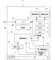
図2は、ディジタル複写機1の構成の概略を示している。
FIG. 2 schematically shows the configuration of the digital copying
ディジタル複写機1は、電源部2、電源制御部30、メイン制御部10、インタフェース部20、画像読取部110、画像形成部210、操作パネル40、およびACプラグ4を備えている。
The
画像読取部110は、原稿台111における原稿読取位置における原稿の画像の読取処理を行う。画像形成部210は、入力された画像データに基づく画像形成処理を行う。インタフェース部20は、外部機器との通信を司る機能を有する。
The
電源制御部30は、電源部2における主電源回路60の起動/停止の切換を行う。本実施形態では主電源回路60が起動している状態を通常動作モードといい、主電源回路60が停止している状態を省電力モードという。主電源回路60の主な機能は、ディジタル複写機1の動作状態に応じて、通常動作モードまたは省電力動作モードのいずれかに切り換えることである。
The power
電源部2は、補助電源回路50および主電源回路60を備えている。補助電源回路50は、主電源回路60による電力の供給が停止している待機モード時において、電源制御部30に電力を供給する。主電源回路60は、メイン制御部10を含むディジタル複写機1の各部に対して電力供給を行う。
The
メイン制御部10は、CPU11、ROM12、RAM13を備えており、ディジタル複写機1の各部を総括的に制御する。メイン制御部10は、上述の電源部2、電源制御部30、インタフェース部20、画像読取部110、画像形成部210、および給紙部300のそれぞれに接続されている。
The
メイン制御部10は電源制御部30を介して主電源回路60の起動/停止の切換制御を行う。メイン制御部10は、主電源回路60を停止させるときに、電源制御部30に対して所定の信号を出力する。
The
メイン制御部10は、ユーザからのコマンドがなく、処理すべきジョブが存在しない状態が所定の時間以上継続すると、コマンド待機時の消費電力を軽減するために省電力動作モードに移行させる。この省電力動作モード時において、通常動作モードに復帰するトリガとなる操作がされるまで、主電源回路60の動作が停止する。
When there is no command from the user and there is no job to be processed for a predetermined time or longer, the
図3は、操作パネル40の構成を示している。操作パネル40は、平面視略長方形状を呈している。操作パネル40は、操作キー31とタッチパネル32とを備えている。
FIG. 3 shows the configuration of the
操作キー31は、テンキー、解除キー、全解除キー、およびスタートキーを含んでいる。タッチパネル32は、ディジタル複写機1の設定内容や動作状態を表示する表示機能とタッチパネル32を介してユーザの入力を受け付ける入力受付機能とを有している。
The
図4は、電源装置2の主要部の構成を示している。商用電源70は、メインスイッチ72、平滑回路71を介して補助電源回路50に接続される。
FIG. 4 shows the configuration of the main part of the
メインスイッチ72は、ディジタル複写機1の主電源のオン/オフを切り換えるためのスイッチである。平滑回路71は、整流・平滑動作を行う回路であり、ダイオードブリッジおよびコンデンサを備えている。補助電源回路50の電力供給端子は、接地されたリレーコイル75および電源制御部30にそれぞれ接続されている。
The
また、商用電源70は、メインスイッチ72、トライアック73、リレー接点74、および平滑回路71を介して主電源回路60に接続される。トライアック73は、そのゲートが主電源回路60に接続されている。リレー接点74は、リレーコイル75によって閉成/開放が切り換えられるノーマル・オープンのリレー接点である。トライアック73およびリレー接点74は、並列に接続されており、それぞれメインスイッチ72および平滑回路71に接続されている。
The
主電源回路60は、MPS信号入力端子76を備えている。MPS信号入力端子76は、主電源回路60をオンにするローレベルの信号(MPS−ON信号)および主電源回路60をオフするハイレベルの信号(MPS−OFF信号)の入力を受け付ける。
The main
また、主電源回路60の電力供給端子は、トライアック73のゲートおよびメイン制御部10にそれぞれ接続されている。
The power supply terminal of the main
同図に示す構成において、メインスイッチ72がオンになるとディジタル複写機1が起動する。起動時には、まず、商用電源70から平滑回路71を経由して補助電源回路50に電流が流れる。続いて、補助電源回路50の電力供給端子からリレーコイル75に電力が供給される。リレーコイル75に電流が流れることにより、リレー接点74が閉成する。リレー接点74が閉成することにより、商用電源70からリレー接点74および平滑回路71を経由して主電源回路60に電流が流れる。
In the configuration shown in the figure, when the
続いて、主電源回路60の電力供給端子からトライアック73のゲートに電力が供給されトライアック73が導通する。また、主電源回路60の電力供給端子からメイン制御部10に対する電力供給が開始され、ディジタル複写機1が動作を開始する。
Subsequently, power is supplied from the power supply terminal of the main
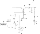
図5は、主電源回路60の要部の構成を示している。主電源回路60において、主巻線68および副巻線69によってスイッチングトランスが構成される。主巻線68の一次側は、スイッチングトランジスタ62を介して接地される。主巻線68の2次側は、ダイオード64Aのアノードに接続されており、ダイオード64Aのカソードは、接地されたコンデンサ64Bおよび電力供給端子に接続されている。
FIG. 5 shows a configuration of a main part of the main
コンデンサ64Bと電力供給端子と間の接続部は、抵抗63、ツェナーダイオード64、発光ダイオード66を介して接地されている。
The connection between the
スイッチングトランジスタ62のゲートは、エミッタが接地されたフォトトランジスタ67および副巻線69に接続される。トランジスタ67トランジスタ67のコレクタは、インバータ61を介して、MPS信号入力端子76に接続されている。MPS信号入力端子76およびインバータ61の間の接続部は、プルアップ抵抗47を介して補助電源回路50に接続されている。
The gate of the switching
MPS−ON信号(ローレベル)がMPS信号入力端子76に入力されると、オープンコレクタのインバータ61とフォトトランジスタ67との間の接続部がハイインピーダンス状態となり、スイッチングトランジスタ62のゲートの強制接地が解除される。このため、スイッチングトランスからスイッチングトランジスタ62のゲートに入力される帰還信号が有効となりスイッチング発振が行われる。このスイッチング発振により、主巻線68の2次側から電力供給端子を介してメイン制御部10に電力の供給が行われる。
When the MPS-ON signal (low level) is input to the MPS
コンデンサ64Bと電力供給端子との間の接続部の電位が、所定の電位に達すると、抵抗63およびツェナーダイオード65を介して発光ダイオード66に電力が流れる。この結果、フォトトランジスタ67がオンになり、スイッチングトランジスタ62のゲートが強制接地され、スイッチングトランスの発振が停止する。このようにスイッチング発振のオン/オフを切り換えることにより、主電源回路60からメイン制御部10に過不足なく電力供給がされる。
When the potential of the connection portion between the
一方で、MPS−OFF信号(ハイレベル)がMPS信号入力端子76に入力されると、スイッチングトランジスタ62のゲートが強制接地され、スイッチングトランスのスイッチング発振が停止する。
On the other hand, when the MPS-OFF signal (high level) is input to the MPS
例えば、通常動作モード時において、電源制御部30からMPS信号入力端子76にMPS−OFF信号が入力されると、スイッチングトランスのスイッチング発振が停止する。また、省電力動作モード時において、電源制御部30からMPS信号入力端子76にMPS−ON信号が入力されると、スイッチングトランスのスイッチング発振が開始される。
For example, when the MPS-OFF signal is input from the power
電源制御部30は、ディジタル複写機1の動作状態に応じて、MPS−ON信号またはMPS−OFF信号をMPS信号入力端子76に出力する。通常、ディジタル複写機1において所定の設定時間以上にわたってコマンド等の入力がされない状態が継続した場合には、メイン制御部10から電源制御部30に所定の信号が出力され、有効な信号を受け付けた電源制御部30がMPS−OFF信号をMPS信号入力端子76に出力する。
The power
図6は、本発明の検出手段の構成を示している。操作パネル40に対する押圧力は図中の上から下に加えられる。
FIG. 6 shows the configuration of the detection means of the present invention. The pressing force on the
図6(A)に示すように、操作パネル40は、スプリング41A,41Bを介してディジタル複写機1の本体に取り付けられる。スプリング41A,41Bはスペーサとして機能するため、操作パネル40とディジタル複写機1の本体との間には、操作パネル40が押圧方向において移動するための空間が形成される。この空間における操作パネル40の下方にはスイッチ42,43が配置される。スイッチ42,43は、操作パネル40の長手方向の両端部に当接するように配置される。スイッチ42,43は、操作パネル40から力を加えられるとオンになるノーマルオープンの接点を有している。なお、本実施形態ではスイッチ42,43によって本発明の検出手段が構成される。
As shown in FIG. 6A, the
図6(B)に示すように、スイッチ42の接点は、第1の端子42Aおよび第1の端子42Bによって構成される。スイッチ43の接点は、第1の端子43Aおよび第1の端子43Bによって構成される。
As shown in FIG. 6B, the contact of the
第1の端子42A,43Aはそれぞれアースに接続される。第2の端子42B,43Bは、接続部44Aにて互いに接続され、この接続部44Aが主電源回路60のMPS信号入力端子76に接続される。接続部44Aと主電源回路60のMPS信号入力端子76との間の接続部44Bは、プルアップ抵抗45を介して補助電源回路50に接続される。
The
操作パネル40に対して押圧力が加わると、スプリング41A,41Bの弾性力に抗して操作パネル40が押し下げられる。押し上げられた操作パネル40の底面がスイッチ42,43に対して力を加え、スイッチ42,43がオンになる。
When a pressing force is applied to the
図6(C)は、操作パネル40の左側に押圧力X1が加えられた状態を示している。操作パネル40の左側に押圧力X1が加えられると、スプリング41Aが圧縮され操作パネル40の左端部が押し下げられる。この結果、操作パネル40の左端部に当接するように配置されたスイッチ42がこの押圧力X1によってオンになる。なお、押圧力X1が解除されると、スプリング41Aの弾性力により操作パネル40の左端部が元の位置に復帰する。
FIG. 6C shows a state in which the pressing force X1 is applied to the left side of the
図6(D)は、操作パネル40の右側に押圧力X2が加えられた状態を示している。操作パネル40の右側に押圧力X2が加えられると、スプリング41Bが圧縮され操作パネル40の右端部が押し下げられる。この結果、操作パネル40の右端部に当接するように配置されたスイッチ43がこの押圧力X2によってオンになる。なお、押圧力X2が解除されると、スプリング41Bの弾性力により操作パネル40の右端部が元の位置に復帰する。
FIG. 6D shows a state in which the pressing force X2 is applied to the right side of the
図6(E)は、操作パネル40の中央部に押圧力X3が加えられた状態を示している。操作パネル40の中央部に押圧力X3が加えられると、スプリング41A,41Bがそれぞれ圧縮されて、スイッチ42,43がオンになる。操作パネル40にどのような力が作用しても、スプリング41A,41Bの復元力によって操作パネル40が元に位置に復帰する。
FIG. 6E shows a state in which the pressing force X3 is applied to the central portion of the
スイッチ42,43のうち少なくともいずれかがオンになることにより、MPS信号入力端子76がアースに接続され、MPS信号入力端子76にローレベルの信号が入力される。このため、操作パネル40に対する押圧力によって省電力動作モードの解除を行うことができる。特に、スイッチ42,43を操作パネル40の長手方向の両端部に対応する位置に配置しているため、操作パネル40に押圧力が作用しているにもかかわらず省電力動作モードが解除されないという不都合が生じにくい。
When at least one of the
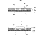
図7(A)は、第2の実施形態における操作キー31の構成を示している。第1のフレキシブルプリント基板(FPC)85Aがスペーサ86を介して第2のフレキシブルプリント基板85Bに接続されている。本実施形態では、第1のフレキシブルプリント基板85Aおよび第2のフレキシブルプリント基板85Bの素材として、ポリエステル(PET)フィルムが使用される。このフィルムの上に、印刷やエッチングにより回路を形成が形成される。
FIG. 7A shows the configuration of the operation key 31 in the second embodiment. A first flexible printed circuit board (FPC) 85A is connected to a second flexible printed
第1のフレキシブルプリント基板85Aの下面に第1の上電極81Aおよび第2の上電極82Aが配置され、第2のフレキシブルプリント基板85Bの上面に第1の下電極81Bおよび第2の下電極82Bが配置される。第1の上電極81Aおよび第1の下電極82Aによりスイッチ81が構成され、第2の上電極82Aおよび第2の下電極82Bによりスイッチ82が構成される。
The first
第1のフレキシブルプリント基板85Aと第2のフレキシブルプリント基板85Bとの間にはスペーサ86によって空間が形成される。この空間において、スイッチ81,82の閉成/解放が切り換えられる。
A space is formed by the
キートップ80に対して押圧力が加えられると、図7(B)に示すように第1のフレキシブルプリント基板85Aが撓み、スイッチ81,82が共に閉成状態になる。キートップ80に加えられた押圧力が解除されると、フレキシブルプリント基板85Aはその弾性により撓んだ状態から元の状態に復帰する。
When a pressing force is applied to the key top 80, the first flexible printed
図8は、操作キーの接続状態を示している。スイッチ81は、ユーザのキー操作を特定するためのスイッチである。スイッチ81の第1の上電極81Aは、メイン制御部10の出力端子14A〜14Eのいずれかに接続され、第1の下電極81Bは、メイン制御部10の入力端子14E〜14Hのいずれかに接続される。ここでは、メイン制御部10の出力端子14A〜14Eから所定のキー操作検出用の信号を出力し、入力端子14E〜14Hに入力される信号を検出することにより、ユーザのキー操作が特定される。
FIG. 8 shows the connection state of the operation keys. The
スイッチ82は、省電力動作モードの解除に使用されるものである。スイッチ82の第2の上電極82Aはバッファ75を介して主電源回路60MPS信号入力端子76に接続される。第2の上電極82Aとバッファ75との間の接続部には、プルアップ抵抗85を介して補助電源回路50が接続される。一方、第2の下電極82Bはアースに接続される。
The
この第2の実施形態では、操作パネル40の操作キー31における各キーに加えられた力を検出して省電力動作モードの解除を行うことを目的としている。このため、操作キー31に加えられた力がスイッチ42,43をオンにする程度に強くなくても、省電力動作モードの解除を行うことができる。なお、この実施形態における操作キー31の構成は、本発明に係る操作パネル40だけでなく、通常の操作パネルに用いることも可能である。
The second embodiment is intended to cancel the power saving operation mode by detecting the force applied to each key in the
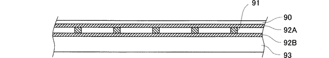
図9は、第3の実施形態におけるタッチパネル32の構成を示している。ここでは、アナログ抵抗膜方式のタッチパネルを説明する。
FIG. 9 shows the configuration of the
タッチパネル32は、下面に透明導電膜92Aが形成されたフィルム90と、上面に透明導電膜92Bが形成されたガラス93をスペーサ91を介して接続することにより構成される。本実施形態では、透明導電膜92A,92Bの素材として、インジウム錫酸化物(ITO)が用いられる。
The
図10は、タッチパネル32における座標読取および省電力動作モード解除の手法の説明図である。透明導電膜92Aの両端には、第1のX電極96Aおよび第2のX電極96Bが接続される。透明導電膜92Bの両端には、第1のY電極97Aおよび第2のY電極97Bが接続される。
FIG. 10 is an explanatory diagram of a technique for reading coordinates on the
図10(A)は、X座標読取手法を示している。X座標の読取の際には、図示しない切換スイッチにより、第1のX電極96Aが主電源回路60に接続され、第2のX電極96Bがアースに接続され、第1のY電極97AがA/Dコンバータ98に接続される。タッチパネル32が押圧されると、透明導電膜92Aにおける押圧操作に対応する箇所が透明導電膜92Bに接触する。この接触箇所の電位をA/Dコンバータ98で測定することにより、押圧操作に係るX座標の読取が行われる。
FIG. 10A shows an X coordinate reading method. When reading the X coordinate, the
図10(B)はY座標読取手法を示している。Y座標の読取の際には、図示しない切換スイッチにより、第2のY電極97Bが主電源回路60に接続され、第1のY電極97Aがアースに接続され、第1のX電極96AがA/Dコンバータ98に接続される。タッチパネル32が押圧されると、透明導電膜92Bにおける押圧操作に対応する箇所が透明導電膜92Aに接触する。この接触箇所の電位をA/Dコンバータ98で測定することにより、押圧操作に係るY座標の読取が行われる。
FIG. 10B shows a Y coordinate reading method. When reading the Y coordinate, the
図10(C)は、省電力動作モード解除の手法を示している。省電力動作モード時には、図示しない切換スイッチにより、第1のY電極97Aがアースに接続され、第1のX電極96Aがバッファを介して主電源回路60のMPS信号入力端子76に接続される。第1のX電極96Aとバッファとの間の接続部は、プルアップ抵抗を介して補助電源回路50に接続される。タッチパネル32が押圧されると、透明導電膜92Aおよび透明導電膜92Bの接触箇所を介して、MPS信号入力端子76がアースに接続される。このため、タッチパネル32の任意の箇所に対する押圧操作を検出して省電力動作モードの解除を行うことが可能になる。
FIG. 10C shows a method of canceling the power saving operation mode. In the power saving operation mode, the
省電力動作モード時には、主電源回路60が停止しており、補助電源回路50によってタッチパネル32への給電を行う。このため、省電力動作モード時には透明導電膜92に電位勾配を与えるための電力が消費されないため、省電力動作モード時における電力消費が抑えられる。
In the power saving operation mode, the main
この第3の実施形態では、操作パネル40のタッチパネル32における任意の箇所に加えられた力を検出して省電力動作モードの解除を行うことを目的としている。このため、タッチパネル32に加えられた力がスイッチ42,43をオンにする程度に強くなくても、省電力動作モードの解除を行うことができる。なお、この実施形態におけるタッチパネル32の構成は、本発明に係る操作パネル40だけでなく、通常の操作パネルに用いることも可能である。
The third embodiment is intended to cancel the power saving operation mode by detecting a force applied to an arbitrary position on the
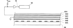
図11は、タッチパネル32のバリエーションとして、ディジタル方式のタッチパネルの例を示している。同図に示すタッチパネルは、下面に透明導電膜94Dが形成された第1のフィルム95A、上面に透明導電膜94Cが形成され下面に透明導電膜94Bが形成された第2のフィルム95B、上面に透明導電膜94Aが形成されたガラス99によって構成される。
FIG. 11 shows an example of a digital touch panel as a variation of the
この構成において、透明導電膜94Cはアースに接続され、透明導電膜94Dはバッファを介して主電源回路60のMPS信号入力端子76に接続される。透明導電膜94Dとバッファとの間の接続部がプルアップ抵抗を介して補助電源回路50に接続される。
In this configuration, the transparent
この結果、省電力動作モード時にタッチパネルに対する押圧操作をトリガとして省電力動作モードの解除が自動的に行われる。特に、省電力動作モード時には主電源回路60が停止しており、省電力動作モード時の電力消費を抑えることができる。
As a result, in the power saving operation mode, the power saving operation mode is automatically canceled using a pressing operation on the touch panel as a trigger. In particular, the main
最後に、上述の実施形態の説明は、すべての点で例示であって、制限的なものではないと考えられるべきである。本発明の範囲は、上述の実施形態ではなく、特許請求の範囲によって示される。さらに、本発明の範囲には、特許請求の範囲と均等の意味および範囲内でのすべての変更が含まれることが意図される。 Finally, the description of the above-described embodiment is to be considered in all respects as illustrative and not restrictive. The scope of the present invention is shown not by the above embodiments but by the claims. Furthermore, the scope of the present invention is intended to include all modifications within the meaning and scope equivalent to the scope of the claims.
1−画像形成装置
2−電源回路
10−メイン制御部
14−スキャナ部
15−プリント部
20−インタフェース部
30−電源制御部
40−操作パネル
DESCRIPTION OF SYMBOLS 1- Image forming apparatus 2-Power supply circuit 10-Main control part 14-Scanner part 15-Print part 20-Interface part 30-Power supply control part 40-Operation panel
Claims (6)
ユーザからの入力操作を受け付ける操作パネルと、を備えた画像形成装置であって、
前記操作パネルに加えられた押圧力を検出する検出手段を有し、
省電力動作モード時に前記前記検出手段が前記押圧力を検出すると、前記電源制御部が前記主電源部を動作させることを特徴とする画像形成装置。 A power supply control unit that switches the operation mode of the device to either a normal operation mode in which the main power supply unit is operated or a power saving operation mode in which only the auxiliary power supply unit is operated by stopping the main power supply unit according to the operation state of the device; ,
An operation panel for receiving an input operation from a user,
Detecting means for detecting a pressing force applied to the operation panel;
The image forming apparatus according to claim 1, wherein when the detection unit detects the pressing force in a power saving operation mode, the power supply control unit operates the main power supply unit.
前記検出手段は、前記操作パネルの移動に伴って開放または閉成するスイッチを有することを特徴とする請求項1に記載の画像形成装置。 The operation panel is movable in a pressing direction related to the pressing force,
The image forming apparatus according to claim 1, wherein the detection unit includes a switch that opens or closes as the operation panel moves.
前記電源制御部は、省電力動作モード時に前記補助電源部から給電され、省電力動作モードから通常動作モードへの復帰時に前記主電源部の起動信号入力端子に所定電位の起動信号を入力し、
前記起動信号入力端子は、前記スイッチを介して所定電位に接続されることを特徴とする請求項1〜3のいずれかに記載の画像形成装置。 The detection means is a switch that is turned on by a pressing force applied to the operation panel,
The power supply control unit is fed from the auxiliary power supply unit during the power saving operation mode, and inputs a start signal having a predetermined potential to the start signal input terminal of the main power supply unit when returning from the power saving operation mode to the normal operation mode.
The image forming apparatus according to claim 1, wherein the activation signal input terminal is connected to a predetermined potential via the switch.
前記キースイッチを構成する第1の端子が所定電位に接続され、第2の端子が前記起動信号入力端子に接続されることを特徴とする請求項4のいずれかに画像形成装置。 Each key on the operation panel further includes a key switch that is changed from an open state to a closed state by a user input operation,
The image forming apparatus according to claim 4, wherein a first terminal constituting the key switch is connected to a predetermined potential, and a second terminal is connected to the activation signal input terminal.
前記接点を構成する第1の導電膜が所定電位に接続され、第2の導電膜が前記起動信号入力端子に接続され、かつ、前記第1の導電膜および前記第2の導電膜に対し入力操作に係る押圧位置を特定するための電位勾配が前記主電源部を介して与えられることを特徴とする請求項4に記載の画像形成装置。 The operation panel is an analog resistance film type touch panel including a contact that is changed from an open state to a closed state by a user input operation,
The first conductive film constituting the contact is connected to a predetermined potential, the second conductive film is connected to the activation signal input terminal, and input to the first conductive film and the second conductive film The image forming apparatus according to claim 4, wherein a potential gradient for specifying a pressed position related to an operation is given through the main power supply unit.
Priority Applications (1)
| Application Number | Priority Date | Filing Date | Title |
|---|---|---|---|
| JP2004105746A JP2005292372A (en) | 2004-03-31 | 2004-03-31 | Image forming apparatus |
Applications Claiming Priority (1)
| Application Number | Priority Date | Filing Date | Title |
|---|---|---|---|
| JP2004105746A JP2005292372A (en) | 2004-03-31 | 2004-03-31 | Image forming apparatus |
Publications (1)
| Publication Number | Publication Date |
|---|---|
| JP2005292372A true JP2005292372A (en) | 2005-10-20 |
Family
ID=35325376
Family Applications (1)
| Application Number | Title | Priority Date | Filing Date |
|---|---|---|---|
| JP2004105746A Pending JP2005292372A (en) | 2004-03-31 | 2004-03-31 | Image forming apparatus |
Country Status (1)
| Country | Link |
|---|---|
| JP (1) | JP2005292372A (en) |
Cited By (2)
| Publication number | Priority date | Publication date | Assignee | Title |
|---|---|---|---|---|
| JP2012176565A (en) * | 2011-02-28 | 2012-09-13 | Casio Electronics Co Ltd | Printing apparatus |
| US10613461B2 (en) * | 2018-04-24 | 2020-04-07 | Kyocera Document Solutions Inc. | Image forming apparatus |
-
2004
- 2004-03-31 JP JP2004105746A patent/JP2005292372A/en active Pending
Cited By (2)
| Publication number | Priority date | Publication date | Assignee | Title |
|---|---|---|---|---|
| JP2012176565A (en) * | 2011-02-28 | 2012-09-13 | Casio Electronics Co Ltd | Printing apparatus |
| US10613461B2 (en) * | 2018-04-24 | 2020-04-07 | Kyocera Document Solutions Inc. | Image forming apparatus |
Similar Documents
| Publication | Publication Date | Title |
|---|---|---|
| US9179015B2 (en) | Image forming apparatus | |
| JP4219293B2 (en) | Image forming apparatus | |
| US5956160A (en) | Image forming system including a printer and scanner having separate housings | |
| JP6222186B2 (en) | Operation panel and image forming apparatus having the same | |
| JP5434971B2 (en) | Image forming apparatus | |
| US20110075231A1 (en) | Image reading apparatus and image forming apparatus | |
| JP2009225321A (en) | Electrical appliance | |
| US20220385773A1 (en) | Display device and image forming apparatus capable of determining whether user's hand having made gesture is right or left hand based on detection result of touch panel and allowing display to display screen for right-hand gesture operation or screen for left-hand gesture operation based on determination result | |
| CN105208237A (en) | Image Forming Apparatus, Method For Controlling Image Forming Apparatus, And Storage Medium | |
| JP6628093B2 (en) | Image forming device | |
| CN104349000B (en) | Numerical value input unit and e-machine | |
| JP2002229393A (en) | Device status display method and device status display device | |
| JP5942654B2 (en) | Image forming apparatus and method of controlling image forming apparatus | |
| JP5668033B2 (en) | Switch mechanism, electronic device, and image forming apparatus | |
| JP2005292372A (en) | Image forming apparatus | |
| US11256352B2 (en) | Image forming apparatus | |
| US20210026287A1 (en) | Power supply apparatus and image forming apparatus | |
| JP4568249B2 (en) | Power supply | |
| JP2011134259A (en) | Display input device and image forming apparatus provided with the same | |
| JP2005205598A (en) | Image forming apparatus | |
| CN109600528B (en) | Operation switch press misdetection prevention device, operation switch press misdetection prevention method, operation panel, and multifunctional peripheral | |
| CN109936673A (en) | Electronic equipment, image forming apparatus, control method and program for electronic equipment | |
| US8611775B2 (en) | Image forming apparatus comprising a fixing pressure switching unit and medium storing image forming programs therein | |
| JP7666000B2 (en) | User interface device, image forming apparatus, control method, and control program | |
| CN109672802B (en) | Switch operation erroneous detection prevention device and switch operation erroneous detection prevention method |