JP2005292371A - Image display device - Google Patents
Image display device Download PDFInfo
- Publication number
- JP2005292371A JP2005292371A JP2004105744A JP2004105744A JP2005292371A JP 2005292371 A JP2005292371 A JP 2005292371A JP 2004105744 A JP2004105744 A JP 2004105744A JP 2004105744 A JP2004105744 A JP 2004105744A JP 2005292371 A JP2005292371 A JP 2005292371A
- Authority
- JP
- Japan
- Prior art keywords
- image
- laser beam
- projection surface
- image display
- display device
- Prior art date
- Legal status (The legal status is an assumption and is not a legal conclusion. Google has not performed a legal analysis and makes no representation as to the accuracy of the status listed.)
- Pending
Links
- 230000003287 optical effect Effects 0.000 claims abstract description 35
- 238000003384 imaging method Methods 0.000 claims abstract description 13
- 238000012937 correction Methods 0.000 claims abstract description 12
- 238000000034 method Methods 0.000 claims description 16
- 238000012545 processing Methods 0.000 claims description 6
- 239000000463 material Substances 0.000 claims description 4
- 239000000758 substrate Substances 0.000 claims description 4
- 238000006243 chemical reaction Methods 0.000 description 17
- 238000012360 testing method Methods 0.000 description 10
- 238000010586 diagram Methods 0.000 description 7
- 238000005516 engineering process Methods 0.000 description 5
- 238000003702 image correction Methods 0.000 description 4
- 238000004519 manufacturing process Methods 0.000 description 3
- 230000015572 biosynthetic process Effects 0.000 description 2
- 238000007796 conventional method Methods 0.000 description 2
- 238000001514 detection method Methods 0.000 description 2
- 238000005530 etching Methods 0.000 description 2
- 238000009434 installation Methods 0.000 description 2
- 238000005259 measurement Methods 0.000 description 2
- XUIMIQQOPSSXEZ-UHFFFAOYSA-N Silicon Chemical compound [Si] XUIMIQQOPSSXEZ-UHFFFAOYSA-N 0.000 description 1
- 229910052782 aluminium Inorganic materials 0.000 description 1
- XAGFODPZIPBFFR-UHFFFAOYSA-N aluminium Chemical compound [Al] XAGFODPZIPBFFR-UHFFFAOYSA-N 0.000 description 1
- 239000004020 conductor Substances 0.000 description 1
- 239000004973 liquid crystal related substance Substances 0.000 description 1
- 229910052751 metal Inorganic materials 0.000 description 1
- 239000002184 metal Substances 0.000 description 1
- 238000005459 micromachining Methods 0.000 description 1
- 239000004065 semiconductor Substances 0.000 description 1
- 229910052710 silicon Inorganic materials 0.000 description 1
- 239000010703 silicon Substances 0.000 description 1
- 238000004544 sputter deposition Methods 0.000 description 1
- 230000009466 transformation Effects 0.000 description 1
- 230000001131 transforming effect Effects 0.000 description 1
- 238000001771 vacuum deposition Methods 0.000 description 1
Images


Landscapes
- Transforming Electric Information Into Light Information (AREA)
- Mechanical Optical Scanning Systems (AREA)
Abstract
Description
本発明は、前方に設置された投射面上に画像を投射して表示を行う画像表示装置に関するものである。 The present invention relates to an image display device that displays an image by projecting it onto a projection surface installed in front.
画像表示装置として、従来から多く利用されてきたCRTによるテレビジョン受像機や情報モニタに加え、近年は液晶表示装置あるいはプラズマ表示装置が商品化され普及してきている。これらは全て、画面拡大などに必要な特別な光学系を用いずに、表示された画像を直接観察する直視型画像表示装置である。技術の進歩に伴い、より高品質な画像信号源が得られるようになり、表示装置に対してはより臨場感の得られる大型化が要求されるようになった。しかし、直視型画像表示装置は、製品の重量や製造工程上の問題で大型化に限界がある。現在、直視型画像表示装置の大型化の限界に対して、それを超える大型の表示装置を実現しているのが投射型表示装置である。投射型画像表示装置は大別すると背面投射型と前面投射型がある。背面投射型画像表示装置は、半透明の投射面上に投射された画像を、投射面の反対側から観察する方式であり、これに対して前面投射型画像表示装置は、反射型の投射面上に投射された画像を、画像表示装置側から観察するものである。背面投射型画像装置は、画像表示素子および画像を拡大投射するために必要な光学系等を含む投射部と投射面が一体化され、リアプロジェクションテレビ等として市場で販売されている。背面投射型画像表示装置は、画面を拡大するための光学系と投射面があらかじめ一体化され調整されているので、使用者は設置における光学系と投射面の相対的な位置調整の必要は無いが、光学系が投射面背後に設置されているので、装置全体の奥行き方向の大きさが大きくなってしまい、さらに重量が重くなってしまうという欠点がある。 In recent years, liquid crystal display devices or plasma display devices have been commercialized and spread in addition to CRT television receivers and information monitors that have been widely used as image display devices. All of these are direct-view image display devices that directly observe the displayed image without using a special optical system necessary for screen enlargement or the like. With the advancement of technology, higher quality image signal sources can be obtained, and display devices have been required to be larger in size so that a sense of reality can be obtained. However, the direct-view image display device is limited in size due to product weight and manufacturing process problems. At present, the projection display device realizes a large display device that exceeds the limit of enlargement of the direct-view image display device. Projection type image display devices are roughly classified into a rear projection type and a front projection type. The rear projection type image display device is a method of observing an image projected on a translucent projection surface from the opposite side of the projection surface, whereas the front projection type image display device is a reflection type projection surface. The image projected above is observed from the image display device side. The rear projection type image device is sold in the market as a rear projection television or the like, in which a projection unit including an image display element and an optical system necessary for enlarging and projecting an image and a projection surface are integrated. In the rear projection type image display device, since the optical system for enlarging the screen and the projection surface are integrated and adjusted in advance, the user does not need to adjust the relative position of the optical system and the projection surface in the installation. However, since the optical system is installed behind the projection surface, there is a drawback that the size of the entire apparatus increases in the depth direction and further increases the weight.
一方、前面投射型画像表示装置は、従来からあったオーバーヘッドプロジェクタ(OHP)に変わり、会議などにおける発表資料の拡大投射表示に利用されるようになり普及しており、市場ではデータプロジェクタあるいは単にプロジェクタとして販売されている。また、家庭においても映画館のような臨場感のある画像を楽しみたいとの要求が増えており、このような要求に応えるための製品として、前面投射型画像表示装置が製品化されてきている。前面投射型画像表示装置は、通常、投射面と画像表示装置は別体で販売されており、使用者は使用環境に応じた投射面を準備し、画像表示装置と投射面を適切な位置に配置しなければならない。前面投射型画像表示装置を設置する場合、画像装置と投射面の位置関係は重要である。画像表示装置の光軸が投射面の垂線と平行である場合、投射面上には歪の無い画像が得られるが、画像表示装置の光軸と投射面の垂線に偏角が生じている場合、投射面上の画像は歪んでしまう。画像の歪は、正確な画像情報提供に支障をきたし、臨場感を損なうため、画像の歪をできる限り低減することが、前面投射型画像表示装置を使用するにあたっては重要である。前面投射型画像表示装置は、通常、画像の歪を補正するための調整手段が備えられており、使用者が設置の際に調整を行う必要があるが、画像の形状に関する調整の項目として、画像の大きさ、位置、台形歪等をそれぞれ、水平方向、垂直方向に関して調整しなければならず、また、各調整項目が独立していない場合もあり、調整は容易でない。 On the other hand, the front projection type image display device is used instead of the conventional overhead projector (OHP), and has been used for enlarged projection display of presentation materials at conferences and the like, and is widely used in the market. It is sold as. In addition, there is an increasing demand for enjoying a realistic image like a movie theater at home, and a front projection image display device has been commercialized as a product to meet such a demand. . In front projection image display devices, the projection surface and the image display device are usually sold separately, and the user prepares a projection surface according to the usage environment, and places the image display device and the projection surface in an appropriate position. Must be placed. When a front projection image display device is installed, the positional relationship between the image device and the projection surface is important. When the optical axis of the image display device is parallel to the perpendicular of the projection surface, an image without distortion is obtained on the projection surface, but there is a declination between the optical axis of the image display device and the perpendicular of the projection surface The image on the projection surface is distorted. In order to use the front projection image display apparatus, it is important to reduce the distortion of the image as much as possible because the distortion of the image hinders the provision of accurate image information and impairs the sense of reality. The front projection type image display device is usually provided with an adjusting means for correcting distortion of an image and needs to be adjusted by a user at the time of installation. The image size, position, trapezoidal distortion, etc. must be adjusted with respect to the horizontal and vertical directions, respectively, and the adjustment items may not be independent, and adjustment is not easy.
投射型画像表示装置の光軸方向と投射面の垂線方向の偏角によって生じる画像の修正を行うための従来の方式および装置は、例えば、特許文献1に示されているものがある。特許文献1に開示された発明は、表示方法および表示装置に関する発明であり、投射光の光軸方向と投射面の垂線方向の偏角に基づいて、表示画面の歪を相殺するように画像データを変更する事を主旨とする発明である。特許文献1による発明では、投射光の光軸と投射面の垂線方向との偏角の検出手段として、表示装置と投射面の少なくとも3点との間の距離を測定することにより求めることを特徴としている。距離測定方法の具体例として超音波を発信し、反射波が戻るまでの時間を計測する方式を示している。また特許文献1には別の方式として、投射面上にテストパターンを表示して、このテストパターン画像を取り込む獲得手段を有し、取り込まれたテストパターン画像と表示装置が有する元のテストパターンの比較により、取り込まれたテストパターンの歪を検出し、検出された歪に基づいて補正量を求め、歪を相殺するように画像データを変更する事を特徴としている。投射面上に表示されたテストパターンの獲得手段の具体例として、CCDカメラを用いることが示されている。 For example, Patent Document 1 discloses a conventional method and apparatus for correcting an image generated by a deviation between an optical axis direction of a projection type image display apparatus and a perpendicular direction of a projection surface. The invention disclosed in Patent Document 1 is an invention relating to a display method and a display device, and image data so as to cancel the distortion of the display screen based on the deviation of the optical axis direction of the projection light and the perpendicular direction of the projection surface. This invention is intended to change the above. In the invention according to Patent Document 1, it is obtained by measuring the distance between the display device and at least three points on the projection surface as means for detecting the deviation angle between the optical axis of the projection light and the perpendicular direction of the projection surface. It is said. As a specific example of the distance measuring method, a method of transmitting an ultrasonic wave and measuring the time until the reflected wave returns is shown. As another method in Patent Document 1, there is an acquisition means for displaying a test pattern on the projection surface and capturing the test pattern image. The captured test pattern image and the original test pattern of the display device are included. The comparison is characterized in that distortion of the captured test pattern is detected, a correction amount is obtained based on the detected distortion, and the image data is changed so as to cancel the distortion. As a specific example of means for acquiring the test pattern displayed on the projection surface, it is shown that a CCD camera is used.
前述の従来技術は投射面に投射された表示画像の歪を補正するための情報を得る手段に関してであるが、表示画像の歪を補正する手段に関しては、表示素子に表示される原画像を変換する方法と、表示素子に表示された画像を投射面に投射するために設けられた光学系において変形を行う方法があり、表示素子に表示される原画像を変換する方法としては、例えば、特許文献2の実施例における図1あるいは図2のブロック図で示されている構成方法を利用することができる。また、非特許文献1のような、前面投射型プロジェクタの水平・垂直台形補正処理を目的とした半導体集積回路が販売されており、画質をある程度維持したまま台形歪補正が可能であり、画像表示装置の原画像変形手段として利用可能である。さらに、表示素子に表示される原画像は変形せずに、表示素子に表示された画像を投射面に投射するために設けられた光学系において変形を行う方法を採ることも可能である。
従来技術は投射面に投射された表示画像の歪を補正するために、表示装置と投射面の少なくとも3点との間の距離を超音波により測定する、あるいは投射面にテストパターンを表示し、このテストパターンをCCDカメラで読み取り、表示装置が有する元のテストパターンと比較することで表示画像の歪情報を取得することで表示画像の歪を補正するための情報を得、その情報を元に、集積回路や光学系を利用し歪の補正を行っている。しかしながら、表示画像の歪を補正するための情報を得る手段として、超音波で距離を測定する方式は、表示装置の使用に際して投射面は表示装置に対して任意の位置に設置されるのであるから、超音波により投射面上の距離測定点を定めるのは一般的に困難であり、距離測定点を定めるための付加装置を追加していくことは、表示装置の製造コストを上げてしまう。また、CCDカメラにより投射面上に表示された画像を獲得する方式は、CCDカメラが高価であり、さらに、取り込まれたテストパターン画像を画像処理するために大規模集積回路を必要とし、表示装置の製造コストを上げてしまう。 In the prior art, in order to correct distortion of the display image projected on the projection surface, the distance between the display device and at least three points on the projection surface is measured by ultrasonic waves, or a test pattern is displayed on the projection surface, By reading this test pattern with a CCD camera and comparing it with the original test pattern of the display device, the distortion information of the display image is obtained to obtain information for correcting the distortion of the display image. The distortion is corrected using an integrated circuit or an optical system. However, as a means for obtaining information for correcting the distortion of the display image, the method of measuring the distance with ultrasonic waves is because the projection plane is installed at an arbitrary position with respect to the display device when the display device is used. In general, it is difficult to determine the distance measurement point on the projection surface with ultrasonic waves, and adding an additional device for determining the distance measurement point increases the manufacturing cost of the display device. Further, the method of acquiring the image displayed on the projection surface by the CCD camera is expensive, and further, a large-scale integrated circuit is required for image processing of the captured test pattern image, and the display device Will increase the manufacturing cost.
本発明はこのような事情を鑑みて成されたものであり、前方にある投射面に映像を投射する画像表示装置において、表示画像の歪の補正を操作者が容易に行うことができ、且つ安価な画像表示装置を提供することである。 The present invention has been made in view of such circumstances, and in an image display device that projects an image on a projection surface in front, an operator can easily correct distortion of a display image, and It is to provide an inexpensive image display device.
入力画像信号に基づき形成された表示素子上の原画像を光学手段を介して投射面上に拡大表示する画像表示装置において、少なくとも、投射面上にレーザー光線を投射するレーザー光線発生器と、該レーザー光線発生器より投射されるレーザー光線を偏向するレーザー光線偏向器と、該レーザー光線偏向器を操作し、前記投射面上に所望する画像外形の頂点を前記投射面上のレーザー光線の結像点で指定する操作盤と、レーザー光線の投射面上の結像点で指定された前記所望する画像外形の頂点におけるレーザー光線の偏向角度より、所望する画像外形に対する前記原画像の補正値を演算する演算器と、該演算器により演算された補正値に基づき前記原画像を補正する画像変形手段を備えたことを特徴とする画像表示装置とする。 In an image display device that enlarges and displays an original image on a display element formed on the basis of an input image signal on a projection surface via an optical means, at least a laser beam generator that projects a laser beam on the projection surface, and the laser beam generator A laser beam deflector for deflecting the projected laser beam, an operation panel for operating the laser beam deflector and designating a vertex of a desired image outer shape on the projection surface by an imaging point of the laser beam on the projection surface, and a laser beam An arithmetic unit for calculating a correction value of the original image with respect to the desired image outer shape based on a deflection angle of the laser beam at the apex of the desired image outer shape designated by the imaging point on the projection surface of the image, and the arithmetic unit An image display device comprising image deformation means for correcting the original image based on the correction value.
前記投射面に、前記操作盤により指定されたレーザー光線の結像点を頂点とする図形を表示する画像表示装置とする。 The image display device displays on the projection surface a graphic having the apex of the image point of the laser beam designated by the operation panel.
前記レーザー光線偏向器がマイクロマシン技術により基板材料を微細加工して製作される小型偏向ミラーである画像表示装置とする。 The laser beam deflector is an image display device which is a small deflecting mirror manufactured by microfabricating a substrate material by micromachine technology.
前記レーザー光線発生器、レーザー光線偏向器および操作盤が前記画像表示装置と別体、あるいは前記画像表示装置より取り外すことが可能である画像表示装置とする。 The laser beam generator, the laser beam deflector, and the operation panel are separated from the image display device or can be removed from the image display device.
本発明の画像表示装置は、操作者がレーザー光線により投射面上に所望する画像外形の頂点を指定するだけで画像の歪補正ができ、操作が容易である。また、比較的安価であるレーザー装置を利用し、大規模な集積回路も必要としないため安価な画像表示装置を提供することが可能になる。 The image display apparatus of the present invention can be easily operated by correcting the distortion of the image only by the operator specifying the desired vertex of the image outline on the projection surface with a laser beam. Further, since a relatively inexpensive laser device is used and a large-scale integrated circuit is not required, an inexpensive image display device can be provided.
投射面に、前記操作盤により指定されたレーザー光線の結像点を頂点とする図形を表示する、つまり投射面に投射面上に表示される画像外形を表示することにより、操作者は投射される画像外形を観測しながら操作を行えるので操作を行い易くなる。 An operator is projected by displaying on the projection surface a figure whose apex is the imaging point of the laser beam specified by the operation panel, that is, by displaying an image outline displayed on the projection surface on the projection surface. The operation can be performed easily while observing the image outline.
マイクロマシン技術により基板材料を微細加工して製作される小型偏向ミラーをレーザー光線の偏向およびその制御に用いることにより、モーター等の駆動系やエンコーダー等の位置検出系が不要となり、画像表示装置の小型化が可能となる。 By using a small deflection mirror, which is manufactured by micromachining the substrate material using micromachine technology, for the deflection and control of the laser beam, there is no need for a drive system such as a motor or a position detection system such as an encoder, and the size of the image display device is reduced. Is possible.
操作盤、レーザー光線偏向器およびレーザー光線発生器を一体化し、該一体化部を画像表示装置から取り外し可能とすることにより、レーザー光線による指示装置として利用することが可能になる。 By integrating the operation panel, the laser beam deflector, and the laser beam generator, and making the integrated unit removable from the image display device, it can be used as a laser beam indicating device.
本発明による画像表示装置は、実施形態の一例として、レーザー光線発生器とレーザー光線偏向器を有し、レーザー光線偏向器は操作者により操作が可能で、投射面上に所望する画像外形の頂点を、投射面におけるレーザー光線の結像点で順次指示し、各点におけるレーザー光線の偏向角度情報を得る。さらに、本発明による画像表示装置は演算器を有し、投射される画像が投射面上で指示された領域に表示されるように、原画像に変形を加えるために必要な原画像変形情報を、前記操作により得られた偏向角度情報から演算して求める。さらに、本発明による画像表示装置は画像変形器を有し、画像変形器は前記原画像変形情報にしたがって原画像を変形し、表示素子に変形画像を送り、表示素子において表示させる。 The image display apparatus according to the present invention includes a laser beam generator and a laser beam deflector as an example of the embodiment. The laser beam deflector can be operated by an operator, and projects the apex of a desired image outline on the projection surface. The laser beam imaging point is sequentially designated on the surface, and the deflection angle information of the laser beam at each point is obtained. Furthermore, the image display apparatus according to the present invention has a computing unit, and stores original image deformation information necessary for deforming the original image so that the projected image is displayed in the designated area on the projection surface. And calculated from the deflection angle information obtained by the above operation. Furthermore, the image display apparatus according to the present invention has an image deformer, which deforms the original image according to the original image deformation information, sends the deformed image to the display element, and displays it on the display element.
図1は本発明の画像表示装置のブロック図である。図1において、11は操作盤、12はレーザー光線偏向器、13はレーザー光線発生器、14は演算器、15は画像変換器、16は表示素子、17は画像信号入力端子である。本発明の画像表示装置は、投射面に投射された画像に歪みがある場合に以下の処理を行うことにより画像を補正し、歪みのない(観測者にとって違和感の無い)画像を投射面に表示するものである。まず、本発明の画像表示装置のレーザー光線発生器13により発生されたレーザー光線は、操作盤11からの信号に従ってレーザー光線偏向器12により偏向され、レーザー光線出射窓から出射され投射面上の一点を指示する。操作盤11は「上」、「下」、「左」、「右」および「決定」のキーで構成されており、操作者は各キーを押下することにより、その指示がレーザー光線偏向器12に与えられ、レーザー光線の偏向角度を変えることができる。レーザー光線の出射方向を上、下、左および右に変えることにより、操作者が投射面上のレーザー光線の結像点を、投射画像が歪み無く表示された場合の画像外形の各頂点に順次指示し「決定」キーを押下する。レーザー光線偏向器12は、操作盤11の「決定」キーが押下された時点の偏向角度情報を演算器14に与え、演算器14は、投射画像外形の各頂点における偏向角度情報から画像変換情報を演算して求め画像変換器15に与える。さらに、演算器14は、表示画像全体の各座標において、補間を行うことにより、画像変換情報を求め画像変換器15に与える。画像変換器15は、演算器14より与えられた画像変換情報に従って、画像信号入力端子17から入力される原画像の画像信号を変形する信号処理を行い、表示素子16が画像表示を行う。あるいは、画像変換情報に従って、光学系の配置を変化させることにより表示素子16が表示する画像の変形を行う。
FIG. 1 is a block diagram of an image display apparatus according to the present invention. In FIG. 1, 11 is an operation panel, 12 is a laser beam deflector, 13 is a laser beam generator, 14 is a calculator, 15 is an image converter, 16 is a display element, and 17 is an image signal input terminal. The image display apparatus of the present invention corrects an image by performing the following processing when an image projected on the projection surface is distorted, and displays an image without distortion (no discomfort for the observer) on the projection surface. To do. First, the laser beam generated by the
図2は本発明による画像表示装置の画像補正に関する操作の説明図であり、20は画像表示装置、21は投射レンズ、22は操作盤、23はレーザー光線出射窓、24は投射面である。また、25a、25b、25cおよび25dは、レーザー光線出射窓23から出射されたレーザー光線の軌跡を表す。投射面24の点26a、26b、26c、26dはそれぞれレーザー光線25a、25b、25c、25dの投射面24における結像点であり、26は結像点26a、26b、26c、26dを頂点とする領域である。操作者は画像表示装置20の設置に際して、画像表示装置20上の操作盤22を操作することにより、画像装置20に備えられた不図示のレーザー光線偏向器が動作し、結像点26aの位置が変わる。この操作により、操作者は結像点26aの位置を、画像が歪みなく表示された時の投射領域の頂点における一点を指定、決定する。同様にして、点26b、26cおよび26dを順次決定する。以上の操作により、操作者は投射面24上に画像が歪みなく表示された時の投射領域をレーザー光線の結像点26a、26b、26c、26dを頂点とする領域26として決定する。
FIG. 2 is an explanatory diagram of operations relating to image correction of the image display device according to the present invention, in which 20 is an image display device, 21 is a projection lens, 22 is an operation panel, 23 is a laser beam exit window, and 24 is a projection surface.
次に、本発明の画像表示装置の画像の歪み補正の理論を説明する。ここでは説明の簡単化のため、投射面24が前方に傾く方向で、投射面24の垂線が光軸に対して偏角を持っている場合を説明する。図3は、画像表示装置20と投射面24の位置および投射光の進路を立体的に示した斜視図である。レーザー光線偏向の光軸と画像投射の光軸を一致させることは構成上困難であるが、両者は平行であり、その平行距離は画像表示装置20から投射面24までの距離に対して無視できるほど小さいので、説明の簡単化のためレーザー光軸と画像光軸は一致していると考え、レーザー光線偏向および画像投射の原点を29で示している。図3に示す点26a、26b、26cおよび26dを頂点とする領域26は、図2における領域26と同一で、投射面24に画像が歪みなく表示された時の投射領域を示している。投射面24が前方に傾く方向で、投射面24の垂線が光軸に対して偏角を持っていた場合、原画像に補正のための変形が加えられないで投射面24に画像が表示されると、画像が投射される領域は領域27であり、点27a、27b、27cおよび27dを頂点とする上辺が短い左右対称の台形となる。また、点28a、28b、28cおよび28dを頂点とする領域28は、光軸に対して垂直に(傾きなく)設置された理想的な投射面に画像が投射された場合の領域を示している。領域28は長方形である。図4は、図3において示した領域26および27を、画像表示装置20側の正面から見た図である。図4において符号を付した各点は、図3において同一の符号が付されている各点と同一である。
Next, the theory of image distortion correction of the image display apparatus of the present invention will be described. Here, for simplification of description, a case will be described in which the
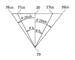
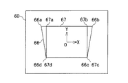
図5は、画像表示装置20と投射面24の位置および投射光の進路を、レーザー光偏向および画像投射の光軸を含む水平面に投影した図である。30はレーザー光線偏向および画像投射の光軸である。点26ahおよび点26bhは、それぞれ、図3における点26aおよび点26bの光軸30を含む水平面への投影点を示している。また、点27ahおよび点27bhは、それぞれ、図3における点27aおよび点27bの光軸30を含む水平面への投影点を示している。29は図3と同じく、レーザー光線偏向および画像投射の原点である。光軸30に対する、原点29から投射面上の点26ah方向への角度をθ26ah、点26bhへの角度をθ26bhとする。角度は原点29を中心として時計回りを正とする。レーザー光線の偏向角度θ26ah、θ26bhは、操作者がレーザー光線により投射面24上に投影される画像が歪みなく表示された時の投射領域を決める操作において、投射面24上の点26aおよび26bを指示する際のレーザー光線の偏向角度から得られる。通常、画像表示装置の光学系は左右対称であることを考えると、光軸30に対する投射画像の広がり角は左右同一で、図5におけるθhとする。図6は表示素子における原画像の変形を説明するための図である。60は表示素子を示している。表示素子60上の点67a、67b、67cおよび67dは、それぞれ、図4において27a、27b、27cおよび27dに投射される点であり、領域67は、図4における領域27に投射される領域である。また、点66a、66b、66cおよび66dは、それぞれ、図4において26a、26b、26cおよび26dに投射されるべき点であり、領域66は、図4において領域26に投射されるべき領域である。光軸30が表示素子60を貫く点を原点Oとして、表示素子60上に、水平方向にX軸、垂直方向にY軸を図6に示すように考える。点66aおよび67aのX軸方向の座標を、それぞれ、x66a、x67aとすると、x66aは図5から明らかに、x67a、θ26ahおよびθhを用いて数式1のように表すことが出来る。同様に、x66bは、x67b、θ26bhおよびθhを用いて数式2のように表すことが出来る。
x66a=x67a×sin|θ26ah|/sin|θh|・・・・・(数式1)
x66b=x67b×sin|θ26bh|/sin|θh|・・・・・(数式2)
点66cおよび66dに関しても、それぞれ、点67cおよび67dからの変換式を求めることができる。本実施例における説明では、水平方向の画像補正のみを説明したが、垂直方向に関しても全く同様に変換式を求めることができる。前述の説明で、画像表示領域の各頂点における画像補正の変換式が求められたが、画像内の各点における変換は、画像表示領域の各頂点における変換を補間することにより、容易に求めることが可能である。以上の説明により表示素子60上の全ての点に関する変換式が求めることができたが、変換を行う手段は従来技術を利用して行うことが可能である。前述の変換式に従い、以上述べた方法により変換を行うことにより、投射面24に表示される画像は、変換前は領域27の台形であったが、変換後は領域26の長方形になり、観察者にとって違和感の無い画像になる。
FIG. 5 is a diagram in which the positions of the
x 66a = x 67a × sin | θ 26ah | / sin | θ h | (Formula 1)
x 66b = x 67b × sin | θ 26bh | / sin | θ h | (Formula 2)
Also for the
実施例2において、本発明の画像表示装置の一実施例を説明する。本実施例の画像表示装置は、実施例1における画像表示装置のレーザー光線偏向器12に、投射面24におけるレーザー光の軌跡が図4における点26a、26b、26cおよび26dを頂点とする四辺形を描くような偏向を行う機能を備えたものである。さらに、操作者は操作盤22を操作することにより、表示領域26の形状を調整することが可能である。実施例1の画像表示装置では、操作者は投射面24上のレーザー光による点を観測しながら領域26の頂点の位置を決定するが、本実施例の画像表示装置では、レーザー光線が投射面24に描いた四辺形を観測しながら領域26を決めることができる。したがって、操作が行い易くなる。
In Example 2, an example of the image display apparatus of the present invention will be described. The image display apparatus of the present embodiment has a quadrilateral shape in which the laser beam trajectory on the
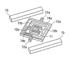
本実施例は、実施例1および実施例2におけるレーザー光線偏向器12にマイクロマシン技術を利用して製作される小型偏向ミラーを使用するものである。マイクロマシン技術を利用して製作される小型偏向ミラーの原理図を図7に示す。図7はレーザー光線を2次元方向に偏向することが可能な小型偏向ミラーである。図7において71はミラー、72aおよび72bはトーションバー、73aおよび73bは可動板、74aおよび74bは電流コイル、75は永久磁石である。トーションバー72aおよび72b、可動面73a、73bは、シリコン基板などをエッチング法などの微細加工技術を利用して形成した物である。また、ミラー71、電流コイル74a、74bはアルミニウムなどの金属を真空蒸着あるいはスパッタリングし、さらに、エッチング技術を利用して形成される。図7を用いて小型偏向ミラーの動作を説明する。電流コイル74aにはトーションバー72aに配された導体を通して電流を流すことが可能であり、電流コイル74aに電流を流すと、2個の永久磁石75により発生している磁界との間にローレンツ力を生じる。このローレンツ力は、トーションバー72aを軸として可動板73aを回転方向に回転させる方向に働き、ローレンツ力による可動板73aの回転トルクと、それに対するトーションバー72aの反作用が釣り合う位置で可動板73aは平衡する。したがって、ミラー71による光線の偏向角度は、電流コイル74aに流す電流値により制御することが可能である。可動板73bも同様に、電流コイル74bに電流を流すことにより、トーションバー72bを軸として回転角度を変えることが可能である。電流コイル74aおよび74bに流す電流は独立に制御可能であるので、図7に示す小型偏向ミラーは、直交する2軸を回転軸として小型偏向ミラーの角度を変えることができる。逆に、電流コイル74aおよび74bの電流値から容易に偏向角度情報を求めることができる。したがって、図7に示す小型偏向ミラーを用いることにより、レーザー光線の偏向およびその制御を行うと、モーターなどの駆動系やエンコーダーなどの位置検出系が不要で、レーザー光線偏向器12の小型化が可能である。さらに、動作が静粛である。以上の特徴から、図7に示される小型偏向ミラーは、本発明による画像表示装置の偏向部として適しているといえる。
In this embodiment, a small deflection mirror manufactured by utilizing micromachine technology is used for the
ところで、本発明の画像表示装置において、操作盤11、レーザー光線偏向器12およびレーザー光線発生器13を一体化し、該一体化部を画像表示装置から取り外し可能とするのも良い。前記一体部を取り外し可能とすることにより、レーザー光線による指示装置として利用することが可能になる。該指示装置は、操作者が投射面上に表示された画像のある部分を、投射面上の画像を観察している他の者に対し指し示す際に利用する装置である。
By the way, in the image display apparatus of the present invention, the
11 操作盤
12 レーザー光線偏向器
13 レーザー光発生器
14 演算器
15 画像変換器
16 表示素子
17 画像信号入力端子
20 画像表示装置
21 投射レンズ
22 操作盤
23 レーザー光出射窓
24 投射面
25a、25b、25c、25d レーザー光線の軌跡
26 レーザー光線の結像点を頂点とする領域
26a、26b、26c、26d レーザー光線の結像点
26ah、26bh それぞれ、26a、26bの水平面投影点
27 投射面上に補正前の画像が表示される領域
27a、27b、27c、27d 領域27の頂点
27ah、27bh それぞれ、26a、26bの水平面投影点
28 光軸に対して垂直に設置された投射面に画像が表示される領域
28a、28b、28c、28d 領域28の頂点
29 レーザー光線偏向および画像投射の原点
30 レーザー光線偏向および画像投射の光軸
60 表示素子
66 表示素子上に補正後の画像が表示される領域
66a、66b、66c、66d 領域66の頂点
67 表示素子上に補正前の画像が表示される領域
67a、67b、67c、67d 領域67の頂点
71 ミラー
72a、72b トーションバー
73a、73b 可動板
74a、74b 電流コイル
75 永久磁石
DESCRIPTION OF
Claims (4)
少なくとも、投射面上にレーザー光線を投射するレーザー光線発生器と、
該レーザー光線発生器より投射されるレーザー光線を偏向するレーザー光線偏向器と、
該レーザー光線偏向器を操作し、前記投射面上に所望する画像外形の頂点を前記投射面上のレーザー光線の結像点で指定する操作盤と、
レーザー光線の投射面上の結像点で指定された前記所望する画像外形の頂点におけるレーザー光線の偏向角度より、所望する画像外形に対する前記原画像の補正値を演算する演算器と、
該演算器により演算された補正値に基づき前記原画像を補正する画像変形手段を備えたことを特徴とする画像表示装置。 In an image display device that enlarges and displays an original image on a display element formed based on an input image signal on a projection surface via an optical means,
At least a laser beam generator for projecting a laser beam onto the projection surface;
A laser beam deflector for deflecting a laser beam projected from the laser beam generator;
An operation panel for operating the laser beam deflector and designating a vertex of a desired image outline on the projection surface by an image point of the laser beam on the projection surface;
A calculator for calculating a correction value of the original image with respect to a desired image outer shape from a deflection angle of the laser beam at a vertex of the desired image outer shape designated by an imaging point on a laser beam projection surface;
An image display device comprising image deformation means for correcting the original image based on a correction value calculated by the calculator.
The said laser beam generator, a laser beam deflector, and an operation panel can be removed from the said image display apparatus separately from the said image display apparatus, The Claim 2 or Claim 3 characterized by the above-mentioned. Image display device.
Priority Applications (1)
| Application Number | Priority Date | Filing Date | Title |
|---|---|---|---|
| JP2004105744A JP2005292371A (en) | 2004-03-31 | 2004-03-31 | Image display device |
Applications Claiming Priority (1)
| Application Number | Priority Date | Filing Date | Title |
|---|---|---|---|
| JP2004105744A JP2005292371A (en) | 2004-03-31 | 2004-03-31 | Image display device |
Publications (1)
| Publication Number | Publication Date |
|---|---|
| JP2005292371A true JP2005292371A (en) | 2005-10-20 |
Family
ID=35325375
Family Applications (1)
| Application Number | Title | Priority Date | Filing Date |
|---|---|---|---|
| JP2004105744A Pending JP2005292371A (en) | 2004-03-31 | 2004-03-31 | Image display device |
Country Status (1)
| Country | Link |
|---|---|
| JP (1) | JP2005292371A (en) |
Cited By (3)
| Publication number | Priority date | Publication date | Assignee | Title |
|---|---|---|---|---|
| JP2009180966A (en) * | 2008-01-31 | 2009-08-13 | Seiko Epson Corp | Image forming apparatus |
| US7990598B2 (en) | 2007-07-06 | 2011-08-02 | Seiko Epson Corporation | Scan-type image display device |
| JP2012533769A (en) * | 2009-07-17 | 2012-12-27 | マイクロビジョン,インク. | Correction of distortion in scanning projector by changing scanning amplitude |
-
2004
- 2004-03-31 JP JP2004105744A patent/JP2005292371A/en active Pending
Cited By (3)
| Publication number | Priority date | Publication date | Assignee | Title |
|---|---|---|---|---|
| US7990598B2 (en) | 2007-07-06 | 2011-08-02 | Seiko Epson Corporation | Scan-type image display device |
| JP2009180966A (en) * | 2008-01-31 | 2009-08-13 | Seiko Epson Corp | Image forming apparatus |
| JP2012533769A (en) * | 2009-07-17 | 2012-12-27 | マイクロビジョン,インク. | Correction of distortion in scanning projector by changing scanning amplitude |
Similar Documents
| Publication | Publication Date | Title |
|---|---|---|
| JP3509652B2 (en) | Projector device | |
| JP3827662B2 (en) | Projection display | |
| CN1823523B (en) | Projection device, method for obtaining inclination angle, and method for correcting projected image | |
| WO2015064371A1 (en) | Vehicle-information projection system and projection device | |
| JP2005227661A (en) | Projector and method of correcting distortion | |
| JPWO2006009314A1 (en) | Image display method, image display apparatus, light scattering means, and image display program | |
| WO2007091341A1 (en) | Image projecting method and projector | |
| JP6702600B2 (en) | Projector and focus adjustment method | |
| JP4199641B2 (en) | Projector device | |
| US20110242421A1 (en) | Image distortion correction apparatus and method | |
| JP2011155412A (en) | Projection system and distortion correction method in the same | |
| JP4380557B2 (en) | Projector, chart image display method and program | |
| KR20130043300A (en) | Apparatus and method for correcting image projected by projector | |
| JPH06249615A (en) | Position detection method | |
| JP3996610B2 (en) | Projector apparatus and image distortion correction method thereof | |
| JP3926311B2 (en) | Projector having tilt angle measuring device | |
| WO2012085990A1 (en) | Projection display device and method for instructing installation attitude | |
| JP2005292371A (en) | Image display device | |
| JP2005136699A (en) | Method for automatically correcting trapezoidal distortion of projection display device | |
| JP5630799B2 (en) | Projection apparatus, projection method, and program | |
| JPH10133276A (en) | Image projection device | |
| JP2004350154A (en) | Image projection apparatus, image processing apparatus and method thereof | |
| JP3709405B2 (en) | Projector having tilt angle measuring device | |
| JP2002112112A (en) | Panoramic image correcting device | |
| JP3757224B2 (en) | Projector having tilt angle measuring device |