JP2005292358A - Projection-type image display device - Google Patents
Projection-type image display device Download PDFInfo
- Publication number
- JP2005292358A JP2005292358A JP2004105506A JP2004105506A JP2005292358A JP 2005292358 A JP2005292358 A JP 2005292358A JP 2004105506 A JP2004105506 A JP 2004105506A JP 2004105506 A JP2004105506 A JP 2004105506A JP 2005292358 A JP2005292358 A JP 2005292358A
- Authority
- JP
- Japan
- Prior art keywords
- light
- illumination light
- reflected
- projection
- image display
- Prior art date
- Legal status (The legal status is an assumption and is not a legal conclusion. Google has not performed a legal analysis and makes no representation as to the accuracy of the status listed.)
- Pending
Links
Images

Abstract
Description
本発明は、投写型画像表示装置に関し、更に詳しくは、ランダム偏光の照明光やカラーフィルタを使用する投写型画像表示装置の光利用効率の改善に関するものである。 The present invention relates to a projection type image display apparatus, and more particularly to improvement of light utilization efficiency of a projection type image display apparatus using randomly polarized illumination light or a color filter.
光源から照射された照明光のエネルギー分布をロッドインテグレーター等の導光手段で均一化し、この均一化された照明光を受光した画像光生成部が光変調することにより画像光を生成し、生成された画像光をスクリーンに投映させる投写型画像表示装置が知られている。この投写型画像表示装置には、光変調方法の違いに応じて透過型画像表示装置や反射型画像表示装置がある。透過型画像表示装置は、画像光生成部として透過型の液晶パネルを使用し、この液晶素子の各液晶セルを映像信号に応じて駆動することで光変調させている。 The energy distribution of the illumination light emitted from the light source is made uniform by a light guide means such as a rod integrator, and the image light generation unit that receives this uniformed illumination light modulates the light to generate and generate image light. A projection-type image display device that projects image light onto a screen is known. As this projection type image display device, there are a transmission type image display device and a reflection type image display device according to the difference in the light modulation method. In the transmissive image display device, a transmissive liquid crystal panel is used as an image light generation unit, and light is modulated by driving each liquid crystal cell of the liquid crystal element according to a video signal.
反射型画像表示装置では、画像光生成部として反射型表示パネルを使用している。反射型表示パネルには、デジタル・マイクロミラー・デバイス(DMD)や、リキッド・クリスタル・オン・シリコン(LCOS)素子等がある。DMDは、受光した照明光を投映光学系に向けて反射させるオン位置と、投映光学系から外れた方向に向けて反射させるオフ位置との間で可変する光反射角可変ミラー素子をマトリックス状に多数個配列したものである。画素を明るく表示させる場合にはミラー素子をオン位置に移動し、暗く表示させる場合にはミラー素子をオフ位置に移動する。こうして照明光の反射方向を制御することで、映像信号に応じた光変調を行う。 In the reflection type image display device, a reflection type display panel is used as the image light generation unit. The reflective display panel includes a digital micromirror device (DMD), a liquid crystal on silicon (LCOS) element, and the like. The DMD has a matrix of light reflection angle variable mirror elements that are variable between an on position where reflected illumination light is reflected toward the projection optical system and an off position where the illumination light is reflected in a direction away from the projection optical system. Many are arranged. When the pixel is displayed brightly, the mirror element is moved to the on position, and when the pixel is darkly displayed, the mirror element is moved to the off position. By controlling the reflection direction of the illumination light in this way, light modulation according to the video signal is performed.
LCOS素子は、シリコン基板上に反射型の液晶パネルを形成したもので、シリコン基板に設けられたトランジスターで液晶を駆動するため高い駆動能力をもち,高開口率で小型・高解像度という特長を備えている。 The LCOS element is a reflection type liquid crystal panel formed on a silicon substrate. The LCOS element has high drive capability for driving the liquid crystal with a transistor provided on the silicon substrate, and has the features of high aperture ratio, small size and high resolution. ing.
例えば、従来の投射型画像表示装置では、光源から照射された照明光の偏光方向を1/4波長板によって変換し、ロッドインテグレーターによって照明光の強度分布を均一化させ、偏光分離素子によって特定の偏光方向の照明光だけを透過させて画像の投映に使用し、他の偏光方向の照明光は光源側に向けて反射させていた。 For example, in a conventional projection-type image display device, the polarization direction of illumination light emitted from a light source is converted by a quarter wavelength plate, the intensity distribution of illumination light is made uniform by a rod integrator, and a specific light is separated by a polarization separation element. Only illumination light in the polarization direction is transmitted and used for projecting the image, and illumination light in other polarization directions is reflected toward the light source side.
偏光分離素子によって反射された照明光を有効に利用するために、特許文献1及び2記載の投写型画像表示装置は、光源と1/4波長板との間に反射板を配置している。この反射板には、中央に光源から照射された光を1/4波長板に向けて透過させる透光部を形成し、この透光部の周囲には偏光分離素子から反射されてきた照明光を1/4波長板に向けて反射する反射面が設けられている。反射面によって反射されて1/4波長板に再び入射された照明光は、偏光方向が再度変換されるため、偏光分離素子を透過して有効に利用される。
In order to effectively use the illumination light reflected by the polarization separation element, the projection-type image display devices described in
上記反射板は、透明なガラス板からなり、光源に対する面と、画像光生成部に対する面の透光部となる部位とにアンチリフレクション膜(AR膜)を形成し、画像光生成部に対する面の透光部の周囲には、アルミニウムや銀等によって反射膜を形成していた。 The reflecting plate is made of a transparent glass plate, and an anti-reflection film (AR film) is formed on a surface that is a light source and a translucent portion of the surface that is the image light generating unit, and the surface of the surface that is facing the image light generating unit. A reflection film is formed of aluminum, silver, or the like around the light transmitting portion.
上述した特許文献1及び2とは異なり、1/4波長板や偏光分離素子等を使用せずに、無偏光(ランダム偏光)の照明光によって画像を投映する投射型画像表示装置も従来より知られている。このランダム偏光の照明光を使用する投射型画像表示装置においても、ロッドインテグレータやリレーレンズ、プリズム等によって照明光が反射され、投映に使用されずに無駄になることがあった。
Unlike the above-described
また、DMDを使用した反射型画像表示装置では、光源から照射された照明光を例えばRGBのカラーフィルタによって色ごとに分離してDMDに入射し、DMDは入力された映像信号に基づいて光を反射して、画像光を生成している。しかし、RGBのカラーフィルタは、対応する色以外の光は反射してしまうため、やはり投映に使用されずに無駄になる照明光があった。これら、ランダム偏光の照明光や、カラーフィルタの反射によって無駄になる照明光の有効利用については、上記特許文献1及び2には記載されていない。
In addition, in a reflective image display device using a DMD, illumination light emitted from a light source is separated into colors by, for example, RGB color filters and incident on the DMD. The DMD emits light based on an input video signal. The image light is generated by reflection. However, since RGB color filters reflect light other than the corresponding color, there is still illumination light that is not used for projection and is wasted. The above-mentioned
更に、上記反射板は、画像光生成部に対する面にAR膜と反射膜とを分けて形成するために、1.透光部の形成部位にレジストマスクを形成、2.透光部の形成部位の周囲に反射膜を形成、3.透光部の形成部位のレジストマスクをエッチングにより除去、4.反射膜の上にレジストマスクを形成、5.透光部の形成部位にAR膜を形成、6.光源側の面にAR膜を形成、7.反射膜上のレジストマスクをエッチングにより除去、という作業を行なっていた。しかし、レジストマスクの形成やエッチングには非常にコストがかかるため、従来の反射板は高価であった。また、反射型画像表示装置は、DMDやLCOS素子が高価であるため、周辺部品である反射板のローコスト化が望まれていた。 Further, since the reflection plate is formed by separately forming the AR film and the reflection film on the surface with respect to the image light generation unit, 1. 1. A resist mask is formed at a site where the light transmitting part is to be formed. 2. A reflective film is formed around the part where the light transmitting part is formed. 3. Remove the resist mask at the site where the light transmitting part is formed by etching; 4. A resist mask is formed on the reflective film. 5. An AR film is formed at the site where the light transmitting part is formed; 6. Form an AR film on the light source side surface; The work of removing the resist mask on the reflective film by etching has been performed. However, since the formation and etching of the resist mask is very costly, the conventional reflector is expensive. Further, since the DMD and LCOS elements are expensive in the reflection type image display device, it is desired to reduce the cost of the reflection plate which is a peripheral component.
本発明は、上記問題点を解決するために、ランダム偏光の照明光や、カラーフィルタを使用する投射型画像表示装置においても照明光を有効に利用できるようにし、かつ反射板をローコストに提供することを目的とする。 In order to solve the above-described problems, the present invention makes it possible to effectively use illumination light even in randomly polarized illumination light or a projection-type image display device using a color filter, and to provide a reflector at a low cost. For the purpose.
上記問題点を解決するために、本発明の投射型画像表示装置は、光源と画像光生成部との間の光路内に、光源から照射された照明光を画像光生成部に向けて通過させる開口と、画像光生成部によって反射されたランダム偏光の照明光を該画像光生成部に向けて反射する反射面とを有する反射板を配置した。また、画像光生成部として、カラーフィルタと表示パネルとを用いた場合には、反射板によってカラーフィルタで反射されたランダム偏光の照明光を反射し、表示パネルに入射させるようにした。更に、反射した照明光が画像光生成部に集光されるように、反射面を傾斜させた。 In order to solve the above problems, the projection type image display apparatus of the present invention allows illumination light emitted from a light source to pass through the optical path between the light source and the image light generation unit toward the image light generation unit. A reflector having an aperture and a reflecting surface that reflects the randomly polarized illumination light reflected by the image light generator toward the image light generator is disposed. Further, when a color filter and a display panel are used as the image light generation unit, the randomly polarized illumination light reflected by the color filter by the reflector is reflected and incident on the display panel. Further, the reflecting surface is inclined so that the reflected illumination light is condensed on the image light generation unit.
本発明によれば、ランダム偏光の照明光を使用する投射型画像表示装置であっても、光路内で反射された照明光を反射板で反射させて有効に利用することができる。また、カラーフィルタを使用する投射型画像表示装置においても、カラーフィルタによって反射された照明光を有効に利用することができる。特に、ランダム偏光の照明光を使用する投射型画像表示装置では、1/4波長板や偏光分離素子等を使用していないため、光源以降の光学素子で反射された光を全て有効に利用することができる。更に、照明光が集光されるように反射面を傾斜させたので、光利用効率を更に向上させることができる。また、反射板には、反射膜とAR膜との塗り分けが必要なくなるため、レジストマスクの形成やエッチング作業が不要になり、反射板を安価に製造することができる。 ADVANTAGE OF THE INVENTION According to this invention, even if it is a projection type image display apparatus which uses the illumination light of a random polarization, the illumination light reflected in the optical path can be reflected by a reflecting plate, and can be utilized effectively. Further, even in a projection type image display device using a color filter, illumination light reflected by the color filter can be used effectively. In particular, a projection-type image display device that uses randomly polarized illumination light does not use a quarter-wave plate, a polarization separation element, or the like, and thus effectively uses all the light reflected by the optical elements after the light source. be able to. Furthermore, since the reflecting surface is inclined so that the illumination light is collected, the light utilization efficiency can be further improved. Further, since it is not necessary to separately coat the reflection film and the AR film on the reflection plate, it is not necessary to form a resist mask or perform an etching operation, and the reflection plate can be manufactured at low cost.
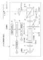
図1は、本発明を実施した反射型画像表示装置の構成を示す概略図である。反射型画像表示装置2は、制御部3と、光学系4とからなる。光学系4は、光源部5,コンデンサレンズ6,反射板7,ロッドインテグレータ8,カラーホイール9,リレーレンズ10,全反射プリズム11,DMD12,投映レンズ13からなる。この反射型画像表示装置2は、3色の画像光を1つのDMD12で生成する単板式である。
FIG. 1 is a schematic diagram showing the configuration of a reflective image display apparatus embodying the present invention. The reflective image display device 2 includes a control unit 3 and an
制御部3は、映像信号受信部16に入力される映像信号に基づいて、反射型画像表示装置2の各部を統括的に制御するマイクロコンピュータ17を備えている。映像信号受信部16には、外部入力端子等に接続されたチューナーやビデオプレーヤー等から、コンポジット信号やコンポーネント信号などの映像信号が入力される。
The control unit 3 includes a
光源部5は、光源5aと、この光源5aが照射する照明光をコンデンサレンズ6に向けて反射するリフレクタ5bとからなる。光源5aとしては、例えば、キセノン管や水銀灯などの白色光源が使用される。
The
ロッドインテグレータ8は、例えば、四角柱のガラス製のロッド内部に万華鏡が形成されたもので、光源部5から入射端面8aに入射された照明光をその内部で全反射することにより、光束を重畳させ、出射端面8bから出射される照明光のエネルギー分布を均一化する。これにより、DMD12の受光面に入射される照明光の強度分布が均一になる。
The
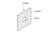
図2に示すように、カラーホイール9は、略円板形状の基板9aに、R光のみを透過して他の光を反射するRフイルタ9b,G光のみを透過して他の光を反射するGフイルタ9c,B光のみを透過透過して他の光を反射するBフイルタ9dの3色のフイルタを基板9aの回転中心からほぼ等距離に配置したものである。カラーホイール9は、カラーホイール駆動部20によって駆動され、その回転開始のタイミングや回転速度は、マイクロコンピュータ17によって制御される。このカラーホイール9が回転することにより、各色のフイルタ9b〜9dが選択的にロッドインテグレータ8の出射端面8bに対面し、照明光がB,G,Rの3色に時分割で色分離される。
As shown in FIG. 2, the color wheel 9 has an R-shaped
全反射プリズム11は、リレーレンズ10からDMD12へ入射する入射光と、DMD12で反射された反射光とを分離するためのものである。全反射プリズム11は、例えば、異なる屈折率を持つ2つの三角プリズムから構成されており、それら2つの三角プリズムの境界に反射面11aが形成される。入射光は、入射角が臨界角よりも大きいため、反射面11aで全反射してDMD12へ入射する。他方、DMD12で反射した反射光は、その入射角が臨界角よりも小さいため、反射面11aを透過する。
The
DMD12は、映像信号受信部16に入力された映像信号に基づいて、マイクロコンピュータ17に接続されたDMD駆動部23によって駆動される。DMD12は、受光面に画素に対応する多数のミラー素子がマトリックス状に配列されている。各ミラー素子は、前記映像信号に基づいて、角度を変化させることにより、受光した照明光の反射方向を変化させる。画素を表示させる場合には、ミラー素子をオン位置に変位させて受光した光をオン光として投映レンズ13に向けて反射させる。他方、画素を表示しない場合にはミラー素子をオフ位置に変位させ、受光した光をオフ光として投映レンズ13から外れた方向に向けて反射させる。画像光は、投映レンズ13に向かうオン光の集合により構成される。
The
投映レンズ13は、図上、簡略化して示しているが、実際には、光軸上に配置された複数のレンズ群と、変倍や焦点調節を行うためのレンズ移動機構とからなる。DMD12によって生成された画像光は、投映レンズ13によってスクリーン26上に結像される。なお、本発明の反射型画像表示装置2では、照明光の偏光方向を変換する1/4波長板や偏光分離素子を使用していない。そのため、DMD12に入射される照明光は、無偏光(ランダム偏光)となる。
The
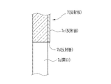
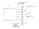
光源部5とロッドインテグレータ8との間に配置された反射板7は、一般にインプットアパーチャーやリサイクルプレートと呼ばれ、光学系4内の照明光の利用効率の向上に利用されている。図3及び図4に示すように、反射板7は、例えば白板ガラスや、テンパックス(登録商標)等の耐熱ガラスによって板状に形成されたもので、その中央には円形の開口7aが形成され、開口7aの周囲でロッドインテグレータ8に対する面には、アルミニウムや銀等が真空蒸着等によってコートされた反射層7bからなる反射面7cが形成されている。図5に示すように、光源部5から照射された照明光は、反射板7の開口7aを通過してロッドインテグレータ8に入射される。
The reflection plate 7 disposed between the
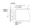
図6に示すように、カラーホイール9の各フィルタ9b〜9dによって反射された照明光、例えばRフィルタ9bによって反射されたG光及びB光や、図5に示すように、全反射プリズム11やリレーレンズ10、ロッドインテグレータ8の入射端面8aで反射された照明光は、光源部5に入射される。従来のランダム偏光の照明光を使用する投射型画像表示装置や、カラーフィルタを使用する投射型画像表示装置では、これらの反射光が無駄になっていた。
As shown in FIG. 6, illumination light reflected by the
しかし、本実施形態の投射型画像表示装置2では、光源部5とロッドインテグレータ8との間の光路内に反射板7を設けたので、光源部5以降の光学素子によって反射された照明光を反射板7の表面の反射面7cによって反射し、再びロッドインテグレータ8に入射するため、照明光の利用効率を向上させることができる。
However, in the projection type image display apparatus 2 of the present embodiment, since the reflecting plate 7 is provided in the optical path between the
従来の反射板は、透明なガラス板の一方の面の中央にAR膜がコートされた透光部を形成し、その周囲に反射膜がコートされた反射面を形成し、反対側の面の全域にもAR膜を形成していた。そのため、AR膜と反射膜とを塗り分けるために、多数回のレジストマスクの形成や、エッチングによるマスク除去を行なう必要があり、高コストであった。これに対し、本願発明の反射板7は、開口7aによって透光領域を形成したので、複数種類の膜を塗り分ける必要がなく、ローコストに製造することができる。なお、反射板7の光源部5側の面には、前面にARコートを施してもよいし、ノーコートでもよい。
In the conventional reflector, a transparent portion coated with an AR film is formed at the center of one surface of a transparent glass plate, and a reflective surface coated with a reflective film is formed around it. An AR film was also formed over the entire area. Therefore, in order to separately coat the AR film and the reflective film, it is necessary to form a resist mask many times and remove the mask by etching, which is expensive. On the other hand, the reflecting plate 7 of the present invention has the light-transmitting region formed by the
次に、上記構成による作用について説明する。反射型画像表示装置2の電源を投入すると、電源部5の光源5aが点灯される。また、DMD駆動部23は、映像信号受信部16に入力された映像信号に基づいてDMD12を駆動し、カラーホイール駆動部20は、DMD12の駆動タイミングに合わせて、カラーホイール9を回転させる。
Next, the effect | action by the said structure is demonstrated. When the reflective image display device 2 is turned on, the
光源5aから照射された照明光は、リフレクタ5bによって反射され、前方のコンデンサレンズ6によって集光される。コンデンサレンズ6から出射された照明光は、反射板7の開口7aを通過してロッドインテグレータ8に入射される。ロッドインテグレータ8は、照明光を内部で全反射してエネルギー分布を均一化し、出射端面8bから出射する。ロッドインテグレータ8から出射された照明光は、カラーホイール9によってRGBの3色に分離され、リレーレンズ10によって全反射プリズム11に入射される。
The illumination light emitted from the
全反射プリズム11に入射されたランダム偏光の照明光は、反射面11aで反射されてDMD12の受光面に入射される。DMD12の受光面では、多数のミラー素子がDMD駆動部23によってオン位置とオフ位置との間で動かされており、オン位置にあるミラー素子は照明光を投映レンズ13に向けてオン光として反射し、オフ位置にあるミラー素子は照明光を投映レンズ13から外れた位置にオフ光として反射する。オン光、すなわち画像光は、投映レンズ13によってスクリーン26上に投映される。
The randomly polarized illumination light incident on the
上述した反射投映動作中に、ロッドインテグレータ8の入射端面8aや、カラーフィルタ9の各フィルタ9b〜9d、リレーレンズ10や全反射プリズム11等によって照明光が光源部5側に向けて反射される。しかし、光源部5に向けて反射された照明光の大部分は、反射板7の反射面7cによって反射されて再びロッドインテグレータ8に入射される。これにより、照明光の利用効率が向上するため、光量の大きな光源を使用しなくても、明るい投映画像を得ることができる。
During the reflection projection operation described above, the illumination light is reflected toward the
なお、上記実施形態では、反射板7の材質としてガラス板を使用したが、アルミニウム等の金属板を使用してもよい。また、この場合には、金属板の一方の面に鏡面加工等を施して反射面としてもよい。これによれば、真空蒸着等によって反射面を形成する必要がないため、反射板7のコストをより下げることができる。 In the above embodiment, a glass plate is used as the material of the reflecting plate 7, but a metal plate such as aluminum may be used. In this case, one surface of the metal plate may be mirror-finished or the like to form a reflecting surface. According to this, since it is not necessary to form a reflecting surface by vacuum deposition or the like, the cost of the reflecting plate 7 can be further reduced.
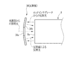
また、平板状の反射板7を使用したが、図7に示すように、開口30aの周囲の反射面30bをロッドインテグレータ8の中心に向けて傾斜させた反射板30を使用してもよい。この反射板30によれば、反射面30bで反射された照明光がロッドインテグレータ8に向けて集光されるため、より照明光の利用効率を高めることができる。なお、この傾斜された反射面30bを有する反射板30を形成する場合には、この形状に形成されたガラス板や金属板を使用し、これに反射面30bを形成すればよい。また、金属板を使用する場合には、反射面30bの形成後に屈曲させてもよい。
Further, although the flat reflection plate 7 is used, a reflection plate 30 in which the
また、上記実施形態では、DMDを使用した反射型画像表示装置を例に説明したが、LCOSを使用した反射型画像表示装置や、ランダム偏光の照明光やカラーフィルタを使用する透過型画像表示装置にも適用することができる。更に、導光手段としてロッドインテグレータを例に説明したが、本発明の反射板は、ガラスロッドやライトトンネル、偏光ロッドと組み合わせて使用することもできる。 In the above embodiment, the reflective image display device using DMD has been described as an example. However, the reflective image display device using LCOS, and the transmissive image display device using random polarized illumination light and color filters. It can also be applied to. Furthermore, although the rod integrator has been described as an example of the light guiding means, the reflector of the present invention can be used in combination with a glass rod, a light tunnel, or a polarizing rod.
2 反射型画像表示装置
3 制御部
4 光学系
5 光源部
7 反射板
7a 開口
7b 反射層
7c 反射面
8 ロッドインテグレータ
9 カラーホイール
11 全反射プリズム
12 DMD
13 投映レンズ
26 スクリーン
DESCRIPTION OF SYMBOLS 2 Reflection type image display apparatus 3
13 Projection lens 26 Screen
Claims (3)
前記光源と画像光生成部との間の光路内に、光源から照射された照明光を画像光生成部に向けて通過させる開口と、画像光生成部によって反射されたランダム偏光の照明光を該画像光生成部に向けて反射する反射面とを有する反射板を配置したことを特徴とする投写型画像表示装置。 A light source that emits illumination light, an image light generator that generates light by modulating the received randomly polarized illumination light according to an input video signal, and projection that projects the generated image light on a screen In a projection-type image display device comprising an optical system,
In the optical path between the light source and the image light generation unit, an opening through which illumination light emitted from the light source passes toward the image light generation unit, and randomly polarized illumination light reflected by the image light generation unit A projection-type image display device comprising a reflector having a reflecting surface that reflects toward an image light generator.
Priority Applications (1)
| Application Number | Priority Date | Filing Date | Title |
|---|---|---|---|
| JP2004105506A JP2005292358A (en) | 2004-03-31 | 2004-03-31 | Projection-type image display device |
Applications Claiming Priority (1)
| Application Number | Priority Date | Filing Date | Title |
|---|---|---|---|
| JP2004105506A JP2005292358A (en) | 2004-03-31 | 2004-03-31 | Projection-type image display device |
Publications (1)
| Publication Number | Publication Date |
|---|---|
| JP2005292358A true JP2005292358A (en) | 2005-10-20 |
Family
ID=35325367
Family Applications (1)
| Application Number | Title | Priority Date | Filing Date |
|---|---|---|---|
| JP2004105506A Pending JP2005292358A (en) | 2004-03-31 | 2004-03-31 | Projection-type image display device |
Country Status (1)
| Country | Link |
|---|---|
| JP (1) | JP2005292358A (en) |
Cited By (3)
| Publication number | Priority date | Publication date | Assignee | Title |
|---|---|---|---|---|
| JP2007147757A (en) * | 2005-11-24 | 2007-06-14 | Nec Viewtechnology Ltd | Rod integrator protection structure and projection type display device |
| CN101604113B (en) * | 2008-06-13 | 2011-03-30 | 中强光电股份有限公司 | Projection optical system and light quantity control assembly for same |
| CN102809882A (en) * | 2012-07-12 | 2012-12-05 | 芜湖雅图数字视频技术有限公司 | Double-lamp illumination device and projector |
-
2004
- 2004-03-31 JP JP2004105506A patent/JP2005292358A/en active Pending
Cited By (6)
| Publication number | Priority date | Publication date | Assignee | Title |
|---|---|---|---|---|
| JP2007147757A (en) * | 2005-11-24 | 2007-06-14 | Nec Viewtechnology Ltd | Rod integrator protection structure and projection type display device |
| US7726819B2 (en) | 2005-11-24 | 2010-06-01 | Nec Viewtechnology, Ltd. | Structure for protecting a rod integrator having a light shield plate with an opening |
| JP4572163B2 (en) * | 2005-11-24 | 2010-10-27 | Necディスプレイソリューションズ株式会社 | Rod integrator protection structure and projection display |
| CN101604113B (en) * | 2008-06-13 | 2011-03-30 | 中强光电股份有限公司 | Projection optical system and light quantity control assembly for same |
| CN102809882A (en) * | 2012-07-12 | 2012-12-05 | 芜湖雅图数字视频技术有限公司 | Double-lamp illumination device and projector |
| CN102809882B (en) * | 2012-07-12 | 2015-01-28 | 芜湖市安曼特微显示科技有限公司 | Double-lamp illumination device and projector |
Similar Documents
| Publication | Publication Date | Title |
|---|---|---|
| JP3069860B1 (en) | Single-panel color projector | |
| JP5694362B2 (en) | Projector device | |
| JP2008116604A (en) | Projector, projection system, program and recording medium | |
| JP6759853B2 (en) | Lighting equipment, image projection equipment | |
| JP2004004793A (en) | Optical system and display apparatus using this | |
| WO2016021002A1 (en) | Light source device, projector, and method for controlling light source device | |
| JP2005003744A (en) | Projection type picture display device | |
| JP2006215536A (en) | Optical system for projection display, and projector incorporating it | |
| JP2006065202A (en) | Projection type picture display device | |
| JP4061898B2 (en) | Illumination apparatus, projector, and driving method thereof | |
| JP2004252112A (en) | Video projection device and illuminator used therefor | |
| JP2016180979A (en) | Projection type display device | |
| JP2005292358A (en) | Projection-type image display device | |
| TWI225160B (en) | Projection system and optical path transfer device thereof | |
| JP2010169914A (en) | Projector | |
| JPH10206813A (en) | Liquid crystal projector and driving method therefor | |
| JP2007133195A (en) | Projector and method for manufacturing projector | |
| JP4127024B2 (en) | projector | |
| JP2010048913A (en) | Projection type display | |
| JP2007127955A (en) | Illuminator and projection type image display device | |
| JP2006098936A (en) | Projection type display device | |
| JP4003606B2 (en) | Illumination optical device and projector using the same | |
| JP4631422B2 (en) | projector | |
| JP2005250384A (en) | Projector | |
| JP2003287803A (en) | Illuminator, and projection type display device and method for driving the same |