JP2005292356A - Image forming apparatus - Google Patents
Image forming apparatus Download PDFInfo
- Publication number
- JP2005292356A JP2005292356A JP2004105504A JP2004105504A JP2005292356A JP 2005292356 A JP2005292356 A JP 2005292356A JP 2004105504 A JP2004105504 A JP 2004105504A JP 2004105504 A JP2004105504 A JP 2004105504A JP 2005292356 A JP2005292356 A JP 2005292356A
- Authority
- JP
- Japan
- Prior art keywords
- image forming
- roller
- recording medium
- forming apparatus
- fixing
- Prior art date
- Legal status (The legal status is an assumption and is not a legal conclusion. Google has not performed a legal analysis and makes no representation as to the accuracy of the status listed.)
- Pending
Links
- 238000000034 method Methods 0.000 claims abstract description 72
- 230000000903 blocking effect Effects 0.000 claims description 20
- 238000000926 separation method Methods 0.000 claims description 19
- 238000012546 transfer Methods 0.000 claims description 18
- 239000000758 substrate Substances 0.000 claims description 12
- 238000010438 heat treatment Methods 0.000 claims description 11
- 238000007599 discharging Methods 0.000 claims description 9
- 108091008695 photoreceptors Proteins 0.000 claims description 5
- 230000001678 irradiating effect Effects 0.000 claims description 4
- 230000015572 biosynthetic process Effects 0.000 claims description 3
- 238000003825 pressing Methods 0.000 description 19
- 239000010410 layer Substances 0.000 description 7
- 239000000428 dust Substances 0.000 description 5
- 229910052751 metal Inorganic materials 0.000 description 5
- 239000002184 metal Substances 0.000 description 5
- 230000001105 regulatory effect Effects 0.000 description 5
- 239000000470 constituent Substances 0.000 description 3
- 230000001276 controlling effect Effects 0.000 description 3
- 238000010030 laminating Methods 0.000 description 3
- 239000000463 material Substances 0.000 description 3
- 229920002379 silicone rubber Polymers 0.000 description 3
- 239000004945 silicone rubber Substances 0.000 description 3
- 229920006311 Urethane elastomer Polymers 0.000 description 2
- 229920001971 elastomer Polymers 0.000 description 2
- OKTJSMMVPCPJKN-UHFFFAOYSA-N Carbon Chemical compound [C] OKTJSMMVPCPJKN-UHFFFAOYSA-N 0.000 description 1
- PXGOKWXKJXAPGV-UHFFFAOYSA-N Fluorine Chemical compound FF PXGOKWXKJXAPGV-UHFFFAOYSA-N 0.000 description 1
- 230000001154 acute effect Effects 0.000 description 1
- 230000002411 adverse Effects 0.000 description 1
- 238000013459 approach Methods 0.000 description 1
- 229910052799 carbon Inorganic materials 0.000 description 1
- 238000010073 coating (rubber) Methods 0.000 description 1
- 239000011247 coating layer Substances 0.000 description 1
- 230000000994 depressogenic effect Effects 0.000 description 1
- 238000013461 design Methods 0.000 description 1
- 238000001514 detection method Methods 0.000 description 1
- 238000011161 development Methods 0.000 description 1
- 239000004744 fabric Substances 0.000 description 1
- 239000010419 fine particle Substances 0.000 description 1
- 229910052731 fluorine Inorganic materials 0.000 description 1
- 239000011737 fluorine Substances 0.000 description 1
- 239000006261 foam material Substances 0.000 description 1
- 229910052736 halogen Inorganic materials 0.000 description 1
- 150000002367 halogens Chemical class 0.000 description 1
- 238000003475 lamination Methods 0.000 description 1
- 230000003287 optical effect Effects 0.000 description 1
- 229920000515 polycarbonate Polymers 0.000 description 1
- 239000004417 polycarbonate Substances 0.000 description 1
- WFKWXMTUELFFGS-UHFFFAOYSA-N tungsten Chemical compound [W] WFKWXMTUELFFGS-UHFFFAOYSA-N 0.000 description 1
- 229910052721 tungsten Inorganic materials 0.000 description 1
- 239000010937 tungsten Substances 0.000 description 1
Images
Classifications
-
- G—PHYSICS
- G03—PHOTOGRAPHY; CINEMATOGRAPHY; ANALOGOUS TECHNIQUES USING WAVES OTHER THAN OPTICAL WAVES; ELECTROGRAPHY; HOLOGRAPHY
- G03G—ELECTROGRAPHY; ELECTROPHOTOGRAPHY; MAGNETOGRAPHY
- G03G21/00—Arrangements not provided for by groups G03G13/00 - G03G19/00, e.g. cleaning, elimination of residual charge
- G03G21/16—Mechanical means for facilitating the maintenance of the apparatus, e.g. modular arrangements
- G03G21/18—Mechanical means for facilitating the maintenance of the apparatus, e.g. modular arrangements using a processing cartridge, whereby the process cartridge comprises at least two image processing means in a single unit
- G03G21/1839—Means for handling the process cartridge in the apparatus body
- G03G21/1842—Means for handling the process cartridge in the apparatus body for guiding and mounting the process cartridge, positioning, alignment, locks
- G03G21/1853—Means for handling the process cartridge in the apparatus body for guiding and mounting the process cartridge, positioning, alignment, locks the process cartridge being mounted perpendicular to the axis of the photosensitive member
-
- G—PHYSICS
- G03—PHOTOGRAPHY; CINEMATOGRAPHY; ANALOGOUS TECHNIQUES USING WAVES OTHER THAN OPTICAL WAVES; ELECTROGRAPHY; HOLOGRAPHY
- G03G—ELECTROGRAPHY; ELECTROPHOTOGRAPHY; MAGNETOGRAPHY
- G03G15/00—Apparatus for electrographic processes using a charge pattern
- G03G15/65—Apparatus which relate to the handling of copy material
- G03G15/6552—Means for discharging uncollated sheet copy material, e.g. discharging rollers, exit trays
-
- G—PHYSICS
- G03—PHOTOGRAPHY; CINEMATOGRAPHY; ANALOGOUS TECHNIQUES USING WAVES OTHER THAN OPTICAL WAVES; ELECTROGRAPHY; HOLOGRAPHY
- G03G—ELECTROGRAPHY; ELECTROPHOTOGRAPHY; MAGNETOGRAPHY
- G03G15/00—Apparatus for electrographic processes using a charge pattern
- G03G15/65—Apparatus which relate to the handling of copy material
- G03G15/6555—Handling of sheet copy material taking place in a specific part of the copy material feeding path
- G03G15/6558—Feeding path after the copy sheet preparation and up to the transfer point, e.g. registering; Deskewing; Correct timing of sheet feeding to the transfer point
- G03G15/6567—Feeding path after the copy sheet preparation and up to the transfer point, e.g. registering; Deskewing; Correct timing of sheet feeding to the transfer point for deskewing or aligning
-
- G—PHYSICS
- G03—PHOTOGRAPHY; CINEMATOGRAPHY; ANALOGOUS TECHNIQUES USING WAVES OTHER THAN OPTICAL WAVES; ELECTROGRAPHY; HOLOGRAPHY
- G03G—ELECTROGRAPHY; ELECTROPHOTOGRAPHY; MAGNETOGRAPHY
- G03G21/00—Arrangements not provided for by groups G03G13/00 - G03G19/00, e.g. cleaning, elimination of residual charge
- G03G21/16—Mechanical means for facilitating the maintenance of the apparatus, e.g. modular arrangements
- G03G21/1604—Arrangement or disposition of the entire apparatus
- G03G21/1609—Arrangement or disposition of the entire apparatus for space saving, e.g. structural arrangements
-
- G—PHYSICS
- G03—PHOTOGRAPHY; CINEMATOGRAPHY; ANALOGOUS TECHNIQUES USING WAVES OTHER THAN OPTICAL WAVES; ELECTROGRAPHY; HOLOGRAPHY
- G03G—ELECTROGRAPHY; ELECTROPHOTOGRAPHY; MAGNETOGRAPHY
- G03G2215/00—Apparatus for electrophotographic processes
- G03G2215/00362—Apparatus for electrophotographic processes relating to the copy medium handling
- G03G2215/00367—The feeding path segment where particular handling of the copy medium occurs, segments being adjacent and non-overlapping. Each segment is identified by the most downstream point in the segment, so that for instance the segment labelled "Fixing device" is referring to the path between the "Transfer device" and the "Fixing device"
- G03G2215/00417—Post-fixing device
- G03G2215/00421—Discharging tray, e.g. devices stabilising the quality of the copy medium, postfixing-treatment, inverting, sorting
-
- G—PHYSICS
- G03—PHOTOGRAPHY; CINEMATOGRAPHY; ANALOGOUS TECHNIQUES USING WAVES OTHER THAN OPTICAL WAVES; ELECTROGRAPHY; HOLOGRAPHY
- G03G—ELECTROGRAPHY; ELECTROPHOTOGRAPHY; MAGNETOGRAPHY
- G03G2215/00—Apparatus for electrophotographic processes
- G03G2215/00362—Apparatus for electrophotographic processes relating to the copy medium handling
- G03G2215/00535—Stable handling of copy medium
- G03G2215/00679—Conveying means details, e.g. roller
-
- G—PHYSICS
- G03—PHOTOGRAPHY; CINEMATOGRAPHY; ANALOGOUS TECHNIQUES USING WAVES OTHER THAN OPTICAL WAVES; ELECTROGRAPHY; HOLOGRAPHY
- G03G—ELECTROGRAPHY; ELECTROPHOTOGRAPHY; MAGNETOGRAPHY
- G03G2221/00—Processes not provided for by group G03G2215/00, e.g. cleaning or residual charge elimination
- G03G2221/16—Mechanical means for facilitating the maintenance of the apparatus, e.g. modular arrangements and complete machine concepts
- G03G2221/18—Cartridge systems
- G03G2221/183—Process cartridge
Landscapes
- Physics & Mathematics (AREA)
- General Physics & Mathematics (AREA)
- Engineering & Computer Science (AREA)
- Computer Vision & Pattern Recognition (AREA)
- Electrophotography Configuration And Component (AREA)
- Mechanical Optical Scanning Systems (AREA)
- Exposure Or Original Feeding In Electrophotography (AREA)
- Sheets, Magazines, And Separation Thereof (AREA)
Abstract
【課題】 感光体上に形成された静電潜像を現像することにより画像形成を行う画像形成装置において、用紙収納部、給紙ローラ、プロセスユニット、およびスキャナユニットの配置を大きく変更することなく、画像形成装置の高さを低く抑えられるようにする。
【解決手段】 プリンタ1において、スキャナユニット16を、プロセスユニット17を取り出し可能なように、脱着方向における給紙ローラ8側が厚みの少ない先細り形状にし、搬送経路の一部を、プロセスユニット17と給紙トレイ6とに挟まれた領域に形成する。そして、搬送経路上に位置する画像形成位置Pを、給紙ローラ8の上端よりも低い位置に設定する。従って、プロセスユニット17の取り出しを容易に行うことができ、且つ、スキャナユニット16を先細り形状にしない場合と比較して、給紙ローラ8の位置におけるプリンタ1の高さを低くすることができる。
【選択図】 図1
An image forming apparatus that forms an image by developing an electrostatic latent image formed on a photoconductor without greatly changing the arrangement of a sheet storage unit, a sheet feeding roller, a process unit, and a scanner unit. The height of the image forming apparatus can be kept low.
In a printer 1, a scanner unit 16 has a taper shape with a small thickness on a paper feed roller 8 side in a detaching direction so that the process unit 17 can be taken out, and a part of a conveyance path is fed with the process unit 17 It is formed in a region sandwiched between the paper tray 6. Then, the image forming position P located on the transport path is set to a position lower than the upper end of the paper feed roller 8. Accordingly, the process unit 17 can be easily taken out, and the height of the printer 1 at the position of the paper feed roller 8 can be reduced as compared with the case where the scanner unit 16 is not tapered.
[Selection] Figure 1
Description
本発明は、感光体上に形成された静電潜像を現像することにより画像形成を行う画像形成装置に関する。 The present invention relates to an image forming apparatus that forms an image by developing an electrostatic latent image formed on a photoreceptor.
従来より、感光体上に形成された静電潜像をトナーにより現像することにより画像形成を行う画像形成装置において、この装置の下方に配置された用紙収納部から給紙ローラを用いて用紙収納部に収納された用紙を1枚ずつ用紙搬送路に供給し、この用紙搬送径路上にて画像を形成し、画像形成装置の上部に位置する排紙トレイに画像形成後の用紙を排出するものが知られている(例えば、特許文献1参照)。 2. Description of the Related Art Conventionally, in an image forming apparatus that forms an image by developing an electrostatic latent image formed on a photoconductor with toner, paper is stored using a paper feed roller from a paper storage unit disposed below the apparatus. The paper stored in the section is supplied to the paper transport path one by one, an image is formed on this paper transport path, and the paper after image formation is discharged to a paper discharge tray located above the image forming apparatus Is known (see, for example, Patent Document 1).
この画像形成装置においては、感光体およびトナータンクを備えたプロセスユニットと、レーザビームを走査することにより感光体に静電潜像を形成するためポリゴンミラーを備えたスキャナユニットと、用紙に転写された可視像を定着させるための定着ユニットとを備えている。 In this image forming apparatus, a process unit including a photoconductor and a toner tank, a scanner unit including a polygon mirror for forming an electrostatic latent image on the photoconductor by scanning a laser beam, and a sheet are transferred to a sheet. And a fixing unit for fixing the visible image.
そして、給紙ローラ近傍において、用紙収納部と、給紙ローラと、プロセスユニットと、スキャナユニットとは、画像形成装置の高さ方向に順に積層された状態で配置されている。 In the vicinity of the paper feed roller, the paper storage unit, the paper feed roller, the process unit, and the scanner unit are arranged in a state of being sequentially stacked in the height direction of the image forming apparatus.
また、定着ユニット近傍において、用紙収納部と、定着ユニットと、排紙トレイとは、画像形成装置の高さ方向に順に積層された状態で配置されている。
また、この画像形成装置において、プロセスユニットは、給紙ローラとスキャナユニットとの間を通過させて水平方向に移動させることにより取り外し可能に構成されており、例えば、トナータンクの内部にあるトナーの残量が少なくなったときには、このプロセスユニットを交換することによりトナーの補給ができるよう構成されている。
Further, in this image forming apparatus, the process unit is configured to be removable by passing between the paper feed roller and the scanner unit and moving in the horizontal direction. For example, the process unit is configured to remove the toner in the toner tank. When the remaining amount is low, the toner can be replenished by replacing the process unit.
しかしながら、上記画像形成装置の給紙ローラ近傍においては、用紙収納部と、給紙ローラと、プロセスユニットと、スキャナユニットとが積層された状態で配置されているので、画像形成装置は各部の高さを足し合わせた分の高さを必要とする。このため画像形成装置の高さが高くなり、小型化できないという問題点があった。 However, in the vicinity of the paper feed roller of the image forming apparatus, the sheet storage unit, the paper feed roller, the process unit, and the scanner unit are arranged in a stacked state. The height of the sum of the lengths is required. For this reason, the height of the image forming apparatus is increased, and there is a problem that it cannot be reduced in size.
また、定着ローラ近傍においても、用紙収納部と、定着ユニットと、排紙トレイとが積層された状態で配置されているので、同様の問題があった。
また、画像形成装置の高さを低くするために、上記各部の配置を大きく変更すると、余分な部品を配置する必要が生じたり、プロセスユニットの取り外しが困難になったりする虞がある。
In the vicinity of the fixing roller, the paper storage unit, the fixing unit, and the paper discharge tray are arranged in a stacked state, and thus the same problem occurs.
In addition, if the arrangement of the above-described parts is greatly changed in order to reduce the height of the image forming apparatus, it may be necessary to arrange extra parts or it may be difficult to remove the process unit.
そこで、このような問題点を鑑み、感光体上に形成された静電潜像を現像することにより画像形成を行う画像形成装置において、用紙収納部、給紙ローラ、プロセスユニット、およびスキャナユニットの配置を大きく変更することなく、画像形成装置の高さを低く抑えられるようにすることを本発明の目的とする。 Therefore, in view of such problems, in an image forming apparatus that forms an image by developing an electrostatic latent image formed on a photoconductor, a paper storage unit, a paper feed roller, a process unit, and a scanner unit An object of the present invention is to keep the height of the image forming apparatus low without significantly changing the arrangement.
かかる目的を達成するために成された請求項1に記載の発明は、ポリゴンミラーによりレーザビームを走査し、前記走査されたレーザビームを感光体に照射することにより前記感光体に静電潜像を形成し、前記感光体に形成された静電潜像を現像剤により現像することにより可視像を生成し、前記感光体上に生成された可視像を画像形成位置にて被記録媒体に転写する画像形成装置であって、前記画像形成装置の下方にて前記被記録媒体を積層した状態で収納する被記録媒体収納部と、前記被記録媒体収納部の上方に位置し、前記被記録媒体収納部に収納された被記録媒体を、前記画像形成位置を経由して前記画像形成装置外まで搬送するための搬送経路と、前記被記録媒体収納部の端部近傍の上方に位置し、前記被記録媒体収納部の最上部に積層された被記録媒体を前記搬送経路に供給する供給ローラと、前記被記録媒体収納部の上方であって前記供給ローラに近接した位置に配置され、少なくとも前記感光体に供給される現像剤を収納するための現像剤収納部を有し、前記供給ローラの上部を通過して、前記画像形成装置から略水平な脱着方向に取り出し可能なプロセスユニットと、前記プロセスユニットの上方に配置されており、少なくとも前記ポリゴンミラーを備えたスキャナユニットと、を備え、前記スキャナユニットは、前記プロセスユニットを取り出し可能なように、前記脱着方向における供給ローラ側が厚みの少ない先細り形状にされており、前記搬送経路の一部は、前記プロセスユニットと前記被記録媒体収納部とに挟まれた領域に形成されており、前記搬送経路上に位置する画像形成位置は、前記供給ローラの上端よりも低い位置にあることを特徴としている。 According to the first aspect of the present invention, the electrostatic latent image is formed on the photosensitive member by irradiating the photosensitive member with the scanned laser beam by scanning the laser beam with a polygon mirror. And developing the electrostatic latent image formed on the photosensitive member with a developer to generate a visible image, and the visible image generated on the photosensitive member is recorded at an image forming position. An image forming apparatus to be transferred to the recording medium, wherein the recording medium storage section stores the recording medium in a stacked state below the image forming apparatus, and is positioned above the recording medium storage section. The recording medium stored in the recording medium storage unit is positioned above the transport path for transporting the recording medium stored outside the image forming apparatus via the image forming position and near the end of the recording medium storage unit. The uppermost part of the recording medium storage unit A supply roller that supplies the stacked recording media to the conveyance path; and a developer that is disposed at a position above the recording medium storage unit and close to the supply roller and that is supplied to at least the photoreceptor. A process unit having a developer storage unit for storing, passing through an upper portion of the supply roller, and being able to be removed from the image forming apparatus in a substantially horizontal detaching direction; and disposed above the process unit. A scanner unit including at least the polygon mirror, and the scanner unit has a taper shape with a small thickness on the supply roller side in the attachment / detachment direction so that the process unit can be taken out, and the transport path Is formed in a region sandwiched between the process unit and the recording medium storage unit, and the conveyance path is Image forming position located above is characterized in that in a position lower than the upper end of the feed roller.
この画像形成装置においては、被記録媒体収納部と、供給ローラと、プロセスユニットと、スキャナユニットとの高さを足し合わせた分の高さが必要になる。つまり、供給ローラの真上の領域に位置する構成要素の厚みが、画像形成装置の高さに最も影響を与える。 In this image forming apparatus, a height corresponding to the sum of the heights of the recording medium storage unit, the supply roller, the process unit, and the scanner unit is required. That is, the thickness of the component located in the region directly above the supply roller has the most influence on the height of the image forming apparatus.
このため、本発明では、画像形成装置の高さを低くするために、供給ローラの真上の領域に位置する構成要素ついては、なるべく厚みを薄くするよう構成している。また、供給ローラの真上以外の領域についても、画像形成装置の高さ方向の空間を有効に使用するよう各構成要素を配置している。しかも構成要素の1つであるプロセスユニットは、供給ローラの上部を通過して、略水平な脱着方向に取り出し可能に構成されている。 For this reason, in the present invention, in order to reduce the height of the image forming apparatus, the components located in the region immediately above the supply roller are configured to be as thin as possible. Further, the components are arranged so that the space in the height direction of the image forming apparatus can be used effectively in the region other than directly above the supply roller. In addition, the process unit, which is one of the constituent elements, is configured to be able to be taken out in a substantially horizontal attaching / detaching direction through the upper part of the supply roller.
即ち、本発明の画像形成装置におけるスキャナユニットは、プロセスユニットを取り出し可能なように、脱着方向における供給ローラ側が厚みの少ない先細り形状にされている。 That is, the scanner unit in the image forming apparatus of the present invention has a tapered shape with a small thickness on the supply roller side in the attaching / detaching direction so that the process unit can be taken out.
また、搬送経路の一部は、プロセスユニットと被記録媒体収納部とに挟まれた領域に形成されており、搬送経路上に位置する画像形成位置は、供給ローラの上端よりも低い位置にあるよう設定されている。 In addition, a part of the transport path is formed in an area sandwiched between the process unit and the recording medium storage unit, and the image forming position located on the transport path is lower than the upper end of the supply roller. It is set as follows.
従って、この画像形成装置によれば、プロセスユニットの取り出しを容易に行うことができ、且つ、スキャナユニットを先細り形状にしない場合と比較して、供給ローラの位置における画像形成装置の高さを低くすることができる。 Therefore, according to this image forming apparatus, the process unit can be easily taken out, and the height of the image forming apparatus at the position of the supply roller is reduced compared to the case where the scanner unit is not tapered. can do.
また、画像形成位置が供給ローラの上端よりも低くなった分だけプロセスユニット等の位置を低くすることができるので、画像形成位置における画像形成装置の高さを低くすることができる。 Further, since the position of the process unit or the like can be lowered by the amount that the image forming position is lower than the upper end of the supply roller, the height of the image forming apparatus at the image forming position can be reduced.
また、プロセスユニットは、請求項2に記載のように、感光体を備えていることが好ましい。
このような画像形成装置によれば、プロセスユニットを交換するときに感光体も交換することができる。
Further, as described in
According to such an image forming apparatus, the photosensitive member can be replaced when the process unit is replaced.
さらに、プロセスユニットは、請求項3に記載のように、感光体上の可視像を被記録部材に転写する転写ローラを備えていることが好ましい。
このような画像形成装置によれば、プロセスユニットを交換するときに転写ローラも交換することができる。加えて、プロセスユニットに転写ローラを設けることで、プロセスユニットの上下方向の高さが大きくなるが、請求項1に記載の構成により、装置本体の高さを大きくすることなく、プロセスユニット脱着のための空間を確保できる。
Furthermore, the process unit preferably includes a transfer roller for transferring the visible image on the photosensitive member to the recording member.
According to such an image forming apparatus, the transfer roller can be replaced when the process unit is replaced. In addition, by providing a transfer roller in the process unit, the height of the process unit in the vertical direction is increased. Space can be secured.
また、スキャナユニットに外壁を構成する上板と下板とを備えている場合には、請求項4に記載のように、下板は、上板よりも水平方向から傾斜して配置されていることが望ましい。 Further, when the scanner unit is provided with an upper plate and a lower plate that constitute an outer wall, the lower plate is arranged so as to be inclined from the horizontal direction with respect to the upper plate as described in claim 4. It is desirable.
このような画像形成装置によれば、確実に供給ローラ近傍における高さを低くすることができる。
さらに、スキャナユニットは、請求項5に記載のように、ポリゴンミラーを回転させるポリゴンモータと、ポリゴンミラーにより走査されたレーザビームを順に反射し、感光体まで導くための2枚の反射鏡と、を備え、先にレーザビームを反射する反射鏡は、スキャナユニット内において、脱着方向における供給ローラ側に位置し、ポリゴンミラー、ポリゴンモータ、および後にレーザビームを反射する反射鏡は、スキャナユニット内において、脱着方向における供給ローラとは反対側に位置することが望ましい。
According to such an image forming apparatus, the height in the vicinity of the supply roller can be reliably reduced.
Further, as described in
このような画像形成装置によれば、スキャナユニットを確実に供給ローラ側が厚みの少ない先細り形状にすることができるので、供給ローラ近傍の高さを低くすることができる。 According to such an image forming apparatus, since the scanner unit can be surely formed into a tapered shape with a small thickness on the supply roller side, the height in the vicinity of the supply roller can be reduced.
また、搬送経路は、請求項6に記載のように、供給ローラの上端から画像形成位置までの全区間で、下向きに傾斜していることが好ましい。
このような画像形成装置であれば、搬送経路近傍の領域のうち、給紙ローラから画像形成位置までの部分における上方の領域を有効に使用することができるので、より画像形成装置を小型化することができる。
Further, as described in
With such an image forming apparatus, the upper area in the area from the paper feed roller to the image forming position in the area near the conveyance path can be used effectively, so the image forming apparatus can be further downsized. be able to.
ところで、感光体および現像剤収納部は、構成要素の中でも比較的厚みがあり、大きなスペースを必要とするものであるため、被記録媒体を搬送するローラの真上に位置する領域には、なるべく配置しないようにすることが望ましい。具体的には、請求項7に記載のように、感光体および現像剤収納部は、供給ローラの真上の領域よりも、脱着方向において画像形成位置側の領域に配置するよう構成するとよい。また、供給ローラから画像形成位置までの搬送径路上に配置されたレジストローラを備えている場合には、請求項8に記載のように、感光体および現像剤収納部は、レジストローラの真上の領域よりも脱着方向において画像形成位置側の領域に配置するよう構成するとよい。 By the way, the photosensitive member and the developer accommodating portion are relatively thick among the constituent elements and require a large space. Therefore, the photosensitive member and the developer accommodating portion are preferably located in a region located directly above the roller for conveying the recording medium. It is desirable not to arrange. Specifically, as described in claim 7, the photoconductor and the developer storage section may be arranged in an area on the image forming position side in the attaching / detaching direction with respect to the area just above the supply roller. In addition, in the case where a registration roller disposed on the conveyance path from the supply roller to the image forming position is provided, the photosensitive member and the developer storage portion are located directly above the registration roller. The image forming position may be arranged in a region closer to the image forming position than the region.
このような画像形成装置によれば、感光体および現像剤収納部は、供給ローラまたはレジストローラと積層することなく配置されるので、感光体および位置現像剤収納部の大きさを確保した状態で画像形成装置を小型化することができる。 According to such an image forming apparatus, the photosensitive member and the developer accommodating portion are arranged without being stacked with the supply roller or the registration roller, so that the size of the photosensitive member and the position developer accommodating portion is ensured. The image forming apparatus can be reduced in size.
また、スキャナユニットは供給ローラ側が厚みの少ない先細り形状とされているが、その先細り部分においても一定の厚みを有するため、スキャナユニットは、請求項9に記載のように、供給ローラの真上の領域よりも脱着方向において画像形成装置側の領域に配置されていることが望ましい。 Further, the scanner unit has a taper shape with a small thickness on the supply roller side. However, since the taper portion has a certain thickness, the scanner unit is located directly above the supply roller. It is desirable that the image forming apparatus is disposed in the region on the image forming apparatus side in the detaching direction from the region.
このような画像形成装置によれば、スキャナユニットは供給ローラと積層されることなく配置されるので、供給ローラが配置される位置における画像形成装置の高さを低くすることができる。 According to such an image forming apparatus, since the scanner unit is disposed without being stacked with the supply roller, the height of the image forming apparatus at the position where the supply roller is disposed can be reduced.
さらに、搬送経路には、請求項10に記載のように、被記録媒体に転写された現像剤を被記録媒体に定着させる定着ローラと、定着ローラと被記録媒体を画像形成装置外部に排出する排出口近傍に配置される排出ローラと、定着ローラから排出ローラまでの区間において、被記録媒体を案内するガイドと、が備えられており、定着ローラから排出ローラまでの区間は、記録可能な最も小さいサイズの被記録媒体の搬送方向における長さよりも短いことが望ましい。
Further, as described in
このような画像形成装置であれば、搬送経路のうち定着ローラから排出ローラまでの間には、その他のローラを設ける必要がないため、その他のローラを配置するためのスペースを節約することができ、延いては画像形成装置を小型化することができる。 In such an image forming apparatus, since it is not necessary to provide other rollers between the fixing roller and the discharge roller in the conveyance path, a space for arranging the other rollers can be saved. As a result, the image forming apparatus can be reduced in size.
また、請求項10に記載の画像形成装置を小型化するためには、定着ローラを通過した被記録媒体をすぐに湾曲させて排出口から排出すればよいが、定着ローラを通過した被記録媒体をすぐに湾曲させると、排出口から排出された被記録媒体が湾曲したままの状態になってしまう虞がある。このため、搬送経路を構成するガイドは、請求項11に記載のように、ガイドにおける排出ローラ近傍の曲率が定着ローラ近傍の曲率よりも大きくなるよう設定されていることが好ましい。
In order to reduce the size of the image forming apparatus according to
このような画像形成装置によれば、被記録媒体のカールを効果的に抑制しながら、排出ローラが配置される位置をなるべく低い位置にすることができる。
さらに、請求項1〜請求項11の何れかに記載の画像形成装置において、搬送経路は、請求項12に記載のように、画像形成位置よりも被記録媒体の搬送方向下流側および供給ローラ近傍にて被記録媒体を反転するような形状を有し、搬送経路を供給ローラの軸方向から見た場合において、S字状に形成されていることが望ましい。
According to such an image forming apparatus, the position where the discharge roller is disposed can be set as low as possible while effectively curling the recording medium.
Furthermore, in the image forming apparatus according to any one of
このような画像形成装置によれば、画像形成装置の大きさの割に長い搬送経路を形成することができるので、搬送経路近傍に配置すべき構成要素を効率的に配置することができる。 According to such an image forming apparatus, it is possible to form a transport path that is long for the size of the image forming apparatus, and thus it is possible to efficiently arrange the components to be disposed in the vicinity of the transport path.
また、請求項1〜請求項12の何れかに記載の画像形成装置において、被記録媒体に転写された現像剤を被記録媒体に定着させる定着ローラを備える定着ユニットと、定着ユニットにより現像剤を定着させた被記録媒体をこの画像形成装置の上部に排出するための排出口と、画像形成装置の上部にて搬送経路を通過して排出口から排出された被記録媒体を積層する被記録媒体積層部と、を備えている場合には、被記録媒体積層部は、請求項13に記載のように、排出口に近い側の底面が定着ユニットの最上面よりも低い位置になるような凹部を備えていることが好ましい。
The image forming apparatus according to
このような画像形成装置によれば、定着ユニットの最上面よりも低い位置に被記録媒体積層部の凹部が形成されているので、被記録媒体の積載量を減らすことなく、排出口の位置を低くすることができる。このため、排出口近傍における画像形成装置の高さを低くすることができる。 According to such an image forming apparatus, since the concave portion of the recording medium stacking portion is formed at a position lower than the uppermost surface of the fixing unit, the position of the discharge port can be set without reducing the loading amount of the recording medium. Can be lowered. For this reason, the height of the image forming apparatus in the vicinity of the discharge port can be reduced.
また、定着ユニットに、通電により発熱される発熱体と、定着ローラの上方に配置され、所定の温度で発熱体への通電を遮断する遮断手段と、定着ローラの真下の位置よりも供給ローラの方向とは反対側にずれた位置に配置され、定着ローラの回転中心方向に押圧される加圧ローラと、を備えている場合には、請求項14に記載のように、遮断手段は、定着ローラおよび加圧ローラの回転中心を結ぶ仮想直線と直行する平面上に位置することが好ましい。 In addition, a heating unit that generates heat upon energization in the fixing unit, a blocking unit that is disposed above the fixing roller and blocks the energization of the heating unit at a predetermined temperature, and a supply roller that is located immediately below the fixing roller. And a pressure roller that is pressed in the direction of the center of rotation of the fixing roller. It is preferably located on a plane perpendicular to the virtual straight line connecting the rotation centers of the roller and the pressure roller.
つまり、遮断手段は、定着ローラから発せられる熱を検知することから、定着ローラの上方に配置されていることが望ましいが、遮断手段が定着ローラの真上の位置や、定着ローラの真上よりも被記録媒体の搬送方向(即ち、定着ローラの真下の位置よりも供給ローラの方向とは反対側にずれた位置)に配置されていると、遮断手段を配置するスペースを確保するために、被記録媒体積層部の凹部の位置が高い位置になってしまうので、本発明の遮断手段は、定着ローラおよび加圧ローラの回転中心を結ぶ仮想直線と直行する平面上に位置するよう構成しているのである。 In other words, since the blocking means detects heat generated from the fixing roller, it is desirable that the blocking means is disposed above the fixing roller. However, the blocking means is located above the fixing roller or directly above the fixing roller. In order to secure a space for disposing the blocking means, it is also arranged in the transport direction of the recording medium (that is, a position shifted to the opposite side of the direction of the supply roller from the position directly below the fixing roller). Since the position of the concave portion of the recording medium lamination portion becomes a high position, the blocking means of the present invention is configured to be positioned on a plane orthogonal to the virtual straight line connecting the rotation centers of the fixing roller and the pressure roller. It is.
従って、このような画像形成装置によれば、被記録媒体積層部における凹部の位置をより低い位置にすることができるので、画像形成装置の高さをより低くすることができる。
さらに、請求項14に記載の画像形成装置において、加圧ローラが露出した状態で、定着ローラと遮断手段とを覆うカバーを備えている場合には、このカバーは、請求項15に記載のように、定着ローラおよび加圧ローラの回転中心を結ぶ仮想直線と直行する平面上において、遮断手段を支持することが好ましい。
Therefore, according to such an image forming apparatus, since the position of the concave portion in the recording medium stacking portion can be lowered, the height of the image forming apparatus can be further reduced.
Further, in the image forming apparatus according to
このような画像形成装置によれば、定着ユニットの下方にカバーを設けない構成にすることができるので、このカバーの厚みの分だけ画像形成装置の高さを低くすることができる。 According to such an image forming apparatus, it is possible to employ a configuration in which a cover is not provided below the fixing unit. Therefore, the height of the image forming apparatus can be reduced by the thickness of the cover.
また、請求項1〜請求項15の何れかに記載の画像形成装置において、画像形成装置を構成する各部を電気的に制御するための電子回路が搭載された基板を備えている場合には、請求項16に記載のように、この基板は、画像形成装置の一側において、前記脱着方向と平行な鉛直面に沿って配置されていることが望ましい。
Further, in the image forming apparatus according to any one of
このような画像形成装置においては、基板の厚みが画像形成装置の高さに反映されないようにすることができるので、基板を寝かせて配置する場合に比べて画像形成装置の高さを低くすることができる。 In such an image forming apparatus, since the thickness of the substrate can be prevented from being reflected in the height of the image forming apparatus, the height of the image forming apparatus can be reduced as compared with the case where the substrate is laid down. Can do.
さらに、請求項1〜請求項16の何れかに記載の画像形成装置において、請求項17に記載のように、感光体は、被記録媒体の搬送方向と直交する方向に延びる円筒形を有し、帯電器により感光体表面が帯電された後に、表面にレーザ光が照射されることにより静電潜像が形成される感光体ドラムであって、画像形成装置には、感光体ドラムを帯電させるための帯電器が、感光体ドラムの半径方向において、水平から45度以内の位置にて感光体ドラムを帯電させるよう配置されていることが望ましい。
Furthermore, in the image forming apparatus according to any one of
このような画像形成装置によれば、帯電器が感光体ドラムの上端から上方にはみ出し難くすることができるので、帯電器の高さが画像形成装置の高さに反映され難くすることができる。 According to such an image forming apparatus, the charger can be prevented from protruding upward from the upper end of the photosensitive drum, so that the height of the charger can be hardly reflected in the height of the image forming apparatus.
また、請求項1〜請求項17の何れかに記載の画像形成装置において、請求項18に記載のように、被記録媒体収納部に積層された被記録媒体を、供給ローラにより被記録媒体を搬送可能な位置まで搬送する送出ローラと、供給ローラにより被記録媒体を搬送可能な位置近傍に配置され、送出ローラにより複数の被記録媒体が供給された場合に、供給された被記録媒体と係合し、被記録媒体収納部の最上位に位置する被記録媒体のみを通過させるための分離パッドと、を備えていることが望ましい。
Further, in the image forming apparatus according to any one of
このような画像形成装置によれば、送出ローラを備えることにより、被記録媒体が分離パッドに加える荷重を低減することができるので、分離パッドや被記録媒体の磨耗を防止することができる。 According to such an image forming apparatus, since the load applied to the recording pad by the recording medium can be reduced by providing the feeding roller, it is possible to prevent the separation pad and the recording medium from being worn.
次に、請求項19に記載の発明は、ポリゴンミラーによりレーザビームを走査し、前記走査されたレーザビームを感光体に照射することにより前記感光体に静電潜像を形成し、前記感光体に形成された静電潜像を現像剤により現像することにより可視像を生成し、前記感光体上に生成された可視像を画像形成位置にて被記録媒体に転写する画像形成装置であって、前記画像形成装置の下方にて前記被記録媒体を積層した状態で収納する被記録媒体収納部と、前記被記録媒体収納部の上方に位置し、前記被記録媒体収納部に収納された被記録媒体を、前記画像形成位置を経由して前記画像形成装置外まで搬送するための搬送経路と、前記被記録媒体に転写された現像剤を前記被記録媒体に定着させる定着ローラを備える定着ユニットと、前記定着ユニットにより現像剤を定着させた被記録媒体を前記画像形成装置の上部に排出するための排出口と、前記画像形成装置の上部にて前記搬送経路を通過して前記排出口から排出された被記録媒体を積層する被記録媒体積層部と、を備え、前記被記録媒体積層部は、前記排出口に近い側の底面が前記定着ユニットの最上面よりも低い位置になるような凹部を有していることを特徴としている。 Next, the invention according to claim 19 scans a laser beam with a polygon mirror, and irradiates the photoconductor with the scanned laser beam, thereby forming an electrostatic latent image on the photoconductor, and the photoconductor An image forming apparatus that generates a visible image by developing the electrostatic latent image formed on the photosensitive member with a developer, and transfers the visible image generated on the photosensitive member to a recording medium at an image forming position. A recording medium storage unit that stores the recording medium in a stacked state below the image forming apparatus; and is positioned above the recording medium storage unit and stored in the recording medium storage unit. A transport path for transporting the recorded medium to the outside of the image forming apparatus via the image forming position, and a fixing roller for fixing the developer transferred to the recorded medium to the recorded medium. A fixing unit, A discharge port for discharging the recording medium on which the developer is fixed by the unit to the upper part of the image forming apparatus; and a target discharged from the discharge port through the conveyance path at the upper part of the image forming apparatus. A recording medium laminating portion for laminating the recording medium, and the recording medium laminating portion has a recess such that the bottom surface on the side close to the discharge port is lower than the uppermost surface of the fixing unit. It is characterized by having.
このような画像形成装置によれば、定着ユニットの最上面よりも低い位置に被記録媒体積層部の凹部が形成されているので、被記録媒体の積載量を減らすことなく、排出口の位置を低くすることができる。このため、排出口近傍における画像形成装置の高さを低くすることができる。 According to such an image forming apparatus, since the concave portion of the recording medium stacking portion is formed at a position lower than the uppermost surface of the fixing unit, the position of the discharge port can be set without reducing the loading amount of the recording medium. Can be lowered. For this reason, the height of the image forming apparatus in the vicinity of the discharge port can be reduced.
さらに、請求項19に記載の画像形成装置において、搬送経路には、請求項20に記載のように、被記録媒体に転写された現像剤を被記録媒体に定着させる定着ローラと、定着ローラと被記録媒体を画像形成装置外部に排出する排出口近傍に配置される排出ローラと、定着ローラから排出ローラまでの区間において、被記録媒体を案内するガイドと、が備えられており、定着ローラから排出ローラまでの区間は、記録可能な最も小さいサイズの被記録媒体の搬送方向における長さよりも短いことが望ましい。
Furthermore, in the image forming apparatus according to
このような画像形成装置であれば、搬送経路のうち定着ローラから排出ローラまでの間には、その他のローラを設ける必要がないため、その他のローラを配置するためのスペースを節約することができ、延いては画像形成装置を小型化することができる。 In such an image forming apparatus, since it is not necessary to provide other rollers between the fixing roller and the discharge roller in the conveyance path, a space for arranging the other rollers can be saved. As a result, the image forming apparatus can be reduced in size.
また、請求項19または請求項20に記載の画像形成装置において、搬送経路を構成するガイドは、請求項21に記載のように、定着ローラを通過後の被記録媒体を湾曲させるための予め定められた曲率を有し、ガイドにおける排出ローラ近傍の曲率は、定着ローラ近傍の曲率よりも大きくなるよう構成されていることが好ましい。
Further, in the image forming apparatus according to claim 19 or 20, the guide constituting the conveyance path is predetermined for curving the recording medium after passing through the fixing roller as described in
このような画像形成装置によれば、被記録媒体のカールを効果的に抑制しながら、排出ローラが配置される位置をなるべく低い位置にすることができる。
また、請求項19〜請求項21の何れかに記載の画像形成装置において、定着ユニットに、通電により発熱される発熱体と、定着ローラの上方に配置され、所定の温度で発熱体への通電を遮断する遮断手段と、定着ローラの真下の位置よりも供給ローラの方向とは反対側にずれた位置に配置され、定着ローラの回転中心方向に押圧される加圧ローラと、を備えている場合には、請求項22に記載のように、遮断手段は、定着ローラおよび加圧ローラの回転中心を結ぶ仮想直線と直行する平面上に位置することが好ましい。
According to such an image forming apparatus, the position where the discharge roller is disposed can be set as low as possible while effectively curling the recording medium.
The image forming apparatus according to any one of
このような画像形成装置によれば、被記録媒体積層部における凹部の位置をより低い位置にすることができるので、画像形成装置の高さをより低くすることができる。
さらに、請求項22に記載の画像形成装置において、加圧ローラが露出した状態で、定着ローラと遮断手段とを覆うカバーを備えている場合には、このカバーは、請求項23に記載のように、定着ローラおよび加圧ローラの回転中心を結ぶ仮想直線と直行する平面上において、遮断手段を支持することが好ましい。
According to such an image forming apparatus, since the position of the concave portion in the recording medium stacking portion can be lowered, the height of the image forming apparatus can be further reduced.
Furthermore, in the image forming apparatus according to
このような画像形成装置によれば、定着ユニットの下方にカバーを設けない構成にすることができるので、このカバーの厚みの分だけ画像形成装置の高さを低くすることができる。 According to such an image forming apparatus, it is possible to employ a configuration in which a cover is not provided below the fixing unit. Therefore, the height of the image forming apparatus can be reduced by the thickness of the cover.
以下に本発明にかかる実施の形態を図面と共に説明する。
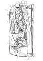
図1は、プリンタ1の要部側断面図である。なお、図1においては、プリンタ1を後述する各種ローラの軸方向から見た図となっており、この図における右側を手前側、左側を奥側と呼ぶこととする。
Embodiments according to the present invention will be described below with reference to the drawings.
FIG. 1 is a cross-sectional side view of a main part of the
図1において、プリンタ1は、本体ケーシング2内に、用紙3(本発明でいう被記録媒体)を給紙するためのフィーダ部4や、給紙された用紙3に所定の画像を形成するための画像形成部5などを備えている。
In FIG. 1, a
また、プリンタ1の上部には、プリンタ1により画像形成され、排出された用紙3を保持するために用いられる排紙トレイ46(本発明でいう被記録媒体積層部)を備えている。
フィーダ部4は、給紙トレイ6(本発明でいう被記録媒体収納部)と、給紙トレイ6内に設けられた用紙押圧板7と、給紙トレイ6の一端側端部の上方に設けられる送出ローラ11、給紙ローラ8(本発明でいう供給ローラ)および分離パッド9と、給紙ローラ8に対向するピンチローラ10と、紙粉取りローラ50と、紙粉取りローラ50に対し用紙3の搬送方向の下流側に設けられるレジストローラ12とを備えている。
In addition, an upper portion of the
The feeder unit 4 is provided above a paper feed tray 6 (recording medium storage unit in the present invention), a paper pressing plate 7 provided in the
給紙トレイ6は、本体ケーシング2内の底部に着脱可能に装着されており、この中に用紙3を積層して収納するために用いられる。この給紙トレイ6は、内部に用紙3を補給する際等に、プリンタ1の手前側(図1においては右側)に引き出される。このとき、フィーダ部4は、給紙ローラ8と分離パッド9との間で分離され、ピンチローラ10と分離パッド9と分離パッド9の裏側に配設されるバネ13とが、給紙トレイ6と一体となって引き出される。
The
用紙押圧板7は、給紙ローラ8に対して遠い方の端部において揺動可能に支持されることによって、給紙ローラ8に対して近い方の端部が上下方向に移動可能とされ、図示しないバネにより上方向に付勢されている。このため、用紙押圧板7は、用紙3の積層量が増えるに従って、給紙ローラ8に対して遠い方の端部を支点として、バネの付勢力に抗して下向きに揺動される。
The paper pressing plate 7 is swingably supported at the end far from the
送出ローラ11は、用紙押圧板7により給紙トレイ6内の最上位に積層された用紙3に当接するよう設定されており、給紙ローラ8により用紙3を搬送可能な位置(給紙ローラ8と分離パッド9の間の位置)まで送る。
The feed roller 11 is set so as to abut on the
次に、分離パッド9は、給紙ローラ8に対向する位置に配設されている。そして分離パッド9の裏側に配設されるバネ13によって、給紙ローラ8に向かって押圧されている。また、この分離パッド9は、複数の用紙3が重なった状態で搬送経路内に供給されることを防止するための機能を備えている。即ち、送出ローラ11により送られてきた用紙3は、給紙ローラ8と分離パッド9とに接触する。このとき、分離パッド9と用紙3との間には、適度な摩擦力が加えられるので、送出ローラ11により複数の用紙3が分離パッドまで送られてきたとしても、最上位に位置する用紙3以外の用紙3は分離パッド9により係止される。このため、給紙ローラ8からは1枚毎に用紙3が供給される。
Next, the separation pad 9 is disposed at a position facing the
そして、給紙ローラ8により給紙された用紙3は、用紙3の搬送経路(図1の2点鎖線にて表示)に送られる。このとき用紙3は、紙粉取りローラ50によって、紙粉が取り除かれた後、レジストローラ12に送られる。また、この搬送経路は、給紙ローラ8の上端から画像形成位置Pまでの全区間においては、水平方向よりも下向きに形成されている。そして、この搬送経路のうち、給紙ローラ8から画像形成位置Pまでの大部分は、プリンタ1の本体側に形成されたガイド部材51と、プロセスユニット17の底面部とにより形成されている。
Then, the
ここで、給紙ローラ8は、用紙3を約180度方向転換させてレジストローラ12に送るが、このとき、給紙ローラ8により用紙3を湾曲させる曲率が大きいと、用紙3が、はがき等の厚みのあるものである場合には、用紙3が折れ曲がってしまうか、或いは用紙3が曲げられる際の抵抗により用紙3はレジストローラ12まで搬送されない虞がある。
Here, the
このため、給紙ローラ8は感光体ドラム27(本発明でいう感光体)や、定着ローラ41等のローラと比べて、直径が大きく設定されている(例えば、感光体ドラム27の直径24mm、定着ローラ41の直径25mmに対して、給紙ローラ8の直径は33mm)。このように給紙ローラ8の直径を比較的大きく設定し、用紙3が湾曲させられる曲率を小さくすれば、給紙ローラ8により用紙3を折り曲げることなく良好に搬送することができる。
Therefore, the diameter of the
また、レジストローラ12は、1対のローラから構成されており、給紙ローラ8の近傍に配置された位置センサ64による検知タイミングに基づいて、駆動および停止の動作が後述する基板90内に配置された制御装置(図示省略)により制御される。そして、この制御により用紙3の斜行が修正される。即ち、制御装置は、給紙ローラ8による用紙3の搬送時において、レジストローラ12は駆動している状態とし、位置センサ64が用紙3の先端を検知すると、レジストローラ12を停止させる。そして、用紙3がレジストローラ12に接触し、弛んだ状態になった頃に、制御装置は再びレジストローラを駆動し、用紙3を画像形成部5に送るようにしている。
Further, the
なお、位置センサ64は、機械式のものであり、用紙3と接触し、用紙3に押されると、用紙3が接触する前の所定の位置から変位するよう構成されている。
また、給紙ローラ8のやや上方には、プリンタ1の手前側からレジストローラ12の位置に直接用紙3を給紙するための手差給紙口14が形成されており、給紙トレイ6に用紙3を収納することなく搬送経路に用紙3を供給することができる。
The
Further, a manual
次に、画像形成部5は、スキャナユニット16、プロセスユニット17、定着ユニット18などを備えている。
スキャナユニット16は、本体ケーシング2内の上部に設けられ、レーザ発光部(図示省略)、ポリゴンモータ25により回転駆動されるポリゴンミラー19、レンズ20および21、反射鏡22および23などを備えており、レーザ発光部から発光される所定の画像データに基づくレーザビームを、図1における一点鎖線で示すように、ポリゴンミラー19、レンズ20、反射鏡22、レンズ21、反射鏡23の順に通過あるいは反射させて、後述するプロセスユニット17における感光体ドラム27の表面上に高速走査にて照射させている。
Next, the
The
より詳しくは、このスキャナユニット16において、ポリゴンミラー19は、感光体ドラム27および後述する画像形成位置Pの真上に配置されており、ポリゴンミラー19に反射されたレーザビームは、反射鏡22に向かって略水平方向に進行する。そして、このレーザビームは、反射鏡22によりポリゴンミラー19のすぐ下方に位置する反射鏡23に向かって反射される。即ち、反射鏡22は入射されるレーザビームを水平方向から15度程度下方に向けて鋭角に反射する。そして、これらの各部(ポリゴンミラー19、レンズ20、21、反射鏡22、23)を備えるスキャナユニット16は、レーザビームの光路を妨げない程度の大きさおよび形状に設定されている。即ち、このスキャナユニット16の上面(上板)は、略水平方向(厳密には給紙ローラ8から遠い方が低くなるよう傾斜して)配置されている。また、スキャナユニット16の下面(下板)は、給紙ローラ8から遠い方がより低くなるよう、上面よりも大きく傾斜している。このため、スキャナユニット16の形状は、ポリゴンミラー19が位置する画像形成位置P側が厚く、給紙ローラ8側が薄い先細り形状となっている。
More specifically, in this
プロセスユニット17は、スキャナユニット16の下方に配設され、本体ケーシング2に対して略水平方向且つ前後方向(図1では左右方向:脱着方向)に着脱自在に装着されており、プロセスユニット17は、ドラムカートリッジ26と、現像カートリッジ28とから構成されている。また、プロセスユニット17とスキャナユニット16との間には、空間が形成されている。
The
プロセスユニット17のうち、ドラムカートリッジ26には、感光体ドラム27、スコロトロン型帯電器29(本発明でいう帯電器)、転写ローラ30を備えている。
また、現像カートリッジ28には、現像ローラ31、層厚規制ブレード32、トナー供給ローラ33およびトナーボックス34などを備えている。そして、この現像カートリッジ28は、ドラムカートリッジ26に対して着脱自在に装着されている。
In the
The developing
ここで、プロセスユニット17を構成する構成要素のうち、感光体ドラム27およびトナーボックス34は、比較的大きなスペースを必要とするものである。このため、この感光体ドラム27およびトナーボックス34は、プロセスユニット17近傍で比較的大きなスペースを必要とする給紙ローラ8、およびレジストローラ12の真上に配置されることがないよう設定されている。
Here, among the constituent elements constituting the
また、トナーボックス34内には、トナー(現像剤)が充填されている。そして、トナーボックス34内のトナーは、トナーボックス34の中心に設けられる回転軸35に支持されるアジテータ36の矢印方向(時計方向)への回転により、攪拌されて、トナーボックス34に設けられたトナー供給口37から放出される。
The toner box 34 is filled with toner (developer). Then, the toner in the toner box 34 is agitated by the rotation of the
トナー供給口37の側方位置には、トナー供給ローラ33が反時計方向に回転可能に配設されており、また、このトナー供給ローラ33に対向して、現像ローラ31が反時計方向に回転可能に配設されている。そして、これらトナー供給ローラ33と現像ローラ31とは、そのそれぞれがある程度圧縮するような状態で互いに当接されている。
A
トナー供給ローラ33は、金属製のローラ軸に、導電性の発泡材料からなるローラが被覆されている。また、現像ローラ31は、金属製のローラ軸に、磁気特性を持たない導電性のゴム材料からなるローラが被覆されている。より具体的には、現像ローラ31のローラ部分は、カーボン微粒子などを含む導電性のウレタンゴムまたはシリコーンゴムからなるローラ本体の表面に、フッ素が含有されているウレタンゴムまたはシリコーンゴムのコート層が被覆されている。なお、現像ローラ31には、現像バイアスが印加される。
The
また、現像ローラ31の近傍には、層厚規制ブレード32が配設されている。この層厚規制ブレード32は、金属の板バネ材からなるブレード本体の先端部に、絶縁性のシリコーンゴムからなる断面半円形状の押圧部40を備えており、現像ローラ31の近くにおいて現像カートリッジ28に支持されて、押圧部40がブレード本体の弾性力によって現像ローラ31上に圧接されるように構成されている。
In addition, a layer
そして、トナー供給口37から放出されるトナーは、トナー供給ローラ33の回転により、現像ローラ31に供給され、この時、トナー供給ローラ33と現像ローラ31との間で正に摩擦帯電され、さらに、現像ローラ31上に供給されたトナーは、現像ローラ31の回転に伴って、層厚規制ブレード32の押圧部40と現像ローラ31との間に進入し、ここでさらに十分に摩擦帯電されて、一定厚さの薄層として現像ローラ31上に担持される。
The toner discharged from the
感光体ドラム27は、現像ローラ31の側方位置において、その現像ローラ31と対向するような状態で時計方向に回転可能に配設されている。この感光体ドラム27は、ドラム本体が接地されるとともに、その表面部分が、ポリカーボネートなどから構成される正帯電性の感光層により形成されている。なお、この感光体ドラム27は、図示しないメインモータからの動力によって回転駆動されるように構成されている。
The
スコロトロン型帯電器29は、感光体ドラム27に接触しないように、所定の間隔を隔てて配設されている。このスコロトロン型帯電器29は、感光体ドラム27の半径方向において、水平方向から約30度上方に配置されている。また、このスコロトロン型帯電器29は、このタングステンなどの帯電用ワイヤからコロナ放電を発生させる正帯電用のスコロトロン型の帯電器であり、感光体ドラム27の表面を一様に正極性に帯電させるように構成されている。
The
そして、感光体ドラム27の表面は、その感光体ドラム27の回転に伴って、まず、スコロトロン型帯電器29により一様に正帯電された後、スキャナユニット16からのレーザビームの高速走査により露光され、所定の画像データに基づく静電潜像が形成される。
The surface of the
次いで、現像ローラ31の回転により、現像ローラ31上に担持されかつ正帯電されているトナーが、感光体ドラム27に対向して接触する時に、感光体ドラム27の表面上に形成される静電潜像、即ち、一様に正帯電されている感光体ドラム27の表面のうち、レーザビームによって露光され電位が下がっている露光部分に供給され、選択的に担持されることによって可視像化され、これによって反転現像が達成される。
Next, the electrostatic charge formed on the surface of the
転写ローラ30は、感光体ドラム27の下方において、この感光体ドラム27に対向するように配置され、ドラムカートリッジ26に反時計方向に回転可能に支持されている。この転写ローラ30は、金属製のローラ軸に、イオン導電性のゴム材料からなるローラが被覆されており、転写時には、転写バイアス(転写順バイアス)が印加されるように構成されている。そのため、感光体ドラム27の表面上に担持された可視像は、用紙3が感光体ドラム27と転写ローラ30との間(画像形成位置P)を通る間に用紙3に転写される。
The
定着ユニット18は、プロセスユニット17よりも用紙搬送方向下流側(奥側)に配設され、ギヤが形成された定着ローラ41、定着ローラ41を押圧する押圧ローラ42(本発明でいう加圧ローラ)、および、サーモスタット18a(本発明でいう遮断手段)を備えている。また、これらの定着ローラ41、およびサーモスタット18aは、カバー18bにより覆われている。
The fixing
定着ローラ41は、金属製で、加熱のためのハロゲンランプを備えている。
押圧ローラ42には、この押圧ローラ42を下方から定着ローラ41の中心軸方向に回転可能に押圧(付勢)するバネ42aを備えている。また、この押圧ローラ42は、定着ローラ41または用紙3と密着し、定着ローラ41と同期して回転するよう構成されている。
The fixing
The
サーモスタット18aは、例えばバイメタルからなり、定着ローラ41から発生される熱に応じて、定着ローラ41を加熱するためのヒータの電源をON・OFFし、加熱ローラ42が異常な高温に加熱されないようにしている。
The
また、このサーモスタット18aは、定着ローラ41の上方であって、押圧ローラ42および定着ローラ41の回転中心を結んだ延長線(仮想線)上に配置されている。このため、サーモスタット18aが定着ローラ41の真上や、定着ローラ41の真上よりも奥側(図1においては左側:用紙3の搬送方向下流側)に配置されていると比べて、排紙トレイ46の凹部46aを位置を低く設定することを可能にしている。
The
カバー18bは、定着ローラ41から発生される熱が定着ユニット18から定着ユニット18外に放出され、本体ケーシング2内の他の機器(例えば、スキャナユニット16等)に悪影響を与えることがないように、定着ローラ41の側方および上方を覆うような形状を有している。ここで、このカバー18bは、押圧ローラ42については、その中心軸(図示省略)のみをバネ42aの付勢方向に移動可能、且つ回転可能に支持しているのみであり、この押圧ローラ42の下半分は、カバー18bから露出した状態になっている。このため、プリンタ1は、カバー18bが押圧ローラ42の下方を覆っている場合と比較して、このカバー18bの厚みの分だけ高さが低く設定されている。
The
このような定着ユニット18において、定着ローラ41は、プロセスユニット17において用紙3上に転写されたトナーを、用紙3が定着ローラ41と押圧ローラ42との間を通過する間に加熱および加圧することにより定着させる。さらに、定着ローラ41は、画像定着後の用紙3を、ガイド部材52、53(本発明でいうガイド)により形成される排紙パスを介して、排出ローラ45まで搬送する。そして、排出ローラ45は、送られてきた用紙3を排紙トレイ46上に排紙する。なお、一対の排出ローラ45は、用紙3をプリンタ1の外部に排出するための排出口24として機能する。
In such a
ここで、用紙3が定着ローラ41により加熱された状態で急に湾曲させられると、用紙3が湾曲した状態から元の湾曲していない状態に戻らなくなる虞がある。このため、定着ローラ41通過後の用紙3が接するガイド部材52、53は、過熱された状態で定着ローラ41通過後には、用紙3を緩やかに湾曲し、排出ローラ45に近づくにつれて、急に湾曲するよう設定されている。
Here, if the
このように構成することによって、用紙3の排出経路の全てを緩やかに湾曲させた場合よりも排出口24の位置を下方にすることができ、用紙3の恒久的な湾曲を防止しつつもプリンタ1の高さを低くし易くなる。
With this configuration, the position of the
また、排紙トレイ46は、プリンタ1の手前側から奥側(図1においては左側)に向かうにつれて、徐々に落ち込んだ形状を有している。この排紙トレイ46の最も落ち込んだ部分(凹部46a)においては、定着ユニット18の上端よりも低い位置になるよう設定されている。このため、排紙トレイ46に積層可能な用紙3の枚数を減らすことなく、排出ローラ45をより低い位置に配置可能にしている。このため、スキャナユニット16が配置されている部分におけるプリンタ1の高さと、排出ローラ45が配置されている位置におけるプリンタ1の高さとを近づけることができ、デザイン性(見栄え)がよいものとなっている。
The
また、このプリンタ1において、前述の各種ローラ、ポリゴンミラー19等を駆動制御するための制御装置が搭載された基板90は、図1における破線にて示すように、用紙3が搬送される搬送経路の両側面(プロセスユニット17を側面から挟むような位置:一側)に配置されている。
In the
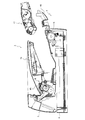
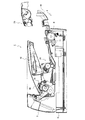
次に、使用者により行なわれるプロセスユニット17の取り外しについて、図2および図3を用いて説明する。図2は、プロセスユニット17を取り外した状態を示す説明図、図3はプロセスユニット17のうち現像カートリッジ28のみを取り外した状態を示す説明図である。
Next, removal of the
図1の状態において、プロセスユニット17を取り外す際には、まず、使用者がプリンタ1のカバー49をプリンタの手前側に開き、図2に示す状態にする。このとき、カバー49は、図示しない支持軸を支点として回動する。
In removing the
そして、プロセスユニット17は、図1の状態から略水平方向にプリンタ1の手前側(脱着方向)に引き出され、給紙ローラ8の上方を通過して取り外される。このとき、プロセスユニット17とスキャナユニット16との間には、前述のように空間が形成されているので、使用者は、プロセスユニット17の手前側(給紙ローラ8に近い側)に位置する取手17aをスキャナユニット16方向に持ち上げて、そのままプロセスユニット17を引き出すことができる。この構成により、プロセスユニット17の奥側(画像形成位置P側)がプリンタ1の本体に引っ掛かり難くし、プロセスユニット17を円滑に引き出すことができるようにされている。
Then, the
また、プロセスユニット17を取り外す場合には、図3に示すように、プロセスユニット17を構成するドラムカートリッジ26をプリンタ1の内部に残した状態で、現像カートリッジ28のみを取り外すこともできるよう構成されている。
Further, when removing the
以上のように詳述したプリンタ1においては、プリンタ1の下方にて用紙3を積層した状態で収納する給紙トレイ6と、給紙トレイ6の上方に位置し、給紙トレイ6に収納された用紙3を、画像形成位置Pを経由してプリンタ1外まで搬送するための搬送経路と、給紙トレイ6の端部近傍の上方に位置し、給紙トレイ6の最上部に積層された用紙3を搬送経路に供給する給紙ローラ8と、給紙トレイ6の上方であって給紙ローラ8に近接した位置に配置され、感光体ドラム27とトナーを収納するためのトナーボックス34とを有し、給紙ローラ8の上部を通過して、プリンタ1から略水平な脱着方向に取り出し可能なプロセスユニット17と、プロセスユニット17の上方に配置されており、少なくともポリゴンミラー19を備えたスキャナユニット16と、を備えている。
In the
そして、スキャナユニット16は、プロセスユニット17を取り出し可能なように、脱着方向における給紙ローラ8側が厚みの少ない先細り形状にされており、搬送経路の一部は、プロセスユニット17と給紙トレイ6とに挟まれた領域に形成されており、搬送経路上に位置する画像形成位置Pは、給紙ローラ8の上端よりも低い位置にある。
The
従って、プロセスユニット17の取り出しを容易に行うことができ、且つ、給紙ローラ8の真上の領域においてスキャナユニット16は厚みが薄くなる先細り形状にされているので、スキャナユニット16を先細り形状にしない場合と比較して、給紙ローラ8の位置におけるプリンタ1の高さを低くすることができる。
Accordingly, the
また、画像形成位置Pが給紙ローラ8の上端よりも低くなった分だけプロセスユニット17等の位置を低くすることができるので、画像形成位置Pにおけるプリンタ1の高さを低くすることができる。
Further, since the position of the
さらに、プロセスユニット17は、感光体ドラム27および転写ローラ30を備えているので、プロセスユニット17を交換するときに感光体ドラム27および転写ローラ30も交換することができる。
Further, since the
また、スキャナユニット16は、外壁を構成する上板と下板とを備えており、下板は、上板よりも水平方向から傾斜して配置されているので、確実に給紙ローラ8近傍における高さを低くすることができる。
In addition, the
さらに、スキャナユニット16は、ポリゴンミラー19を回転させるポリゴンモータ25と、ポリゴンミラー19により走査されたレーザビームを順に反射し、感光体ドラム27まで導くための2枚の反射鏡22,23と、を備え、先にレーザビームを反射する反射鏡22は、スキャナユニット16内において、プロセスユニット17の脱着方向における給紙ローラ8側に位置し、ポリゴンミラー19、ポリゴンモータ25、および後にレーザビームを反射する反射鏡23は、スキャナユニット16において、プロセスユニット17の脱着方向における給紙ローラ8とは反対側に位置するよう構成されている。
Further, the
従って、スキャナユニット16を確実に給紙ローラ8側が厚みの少ない先細り形状にすることができるので、給紙ローラ8近傍の高さを低くすることができる。
また、搬送経路は、給紙ローラ8の上端から画像形成位置Pまでの全区間で、下向きに傾斜しているので、搬送経路近傍の領域のうち、給紙ローラ8から画像形成位置Pまでの部分における上方の領域を有効に使用することができ、延いてはプリンタ1を小型化することができる。
Therefore, since the
Further, since the conveyance path is inclined downward in the entire section from the upper end of the
さらに、プロセスユニット17を構成する感光体ドラム27およびトナーボックス34は、給紙ローラ8の真上の領域およびレジストローラ12よりも脱着方向において画像形成位置P側の領域に配置され、感光体ドラム27およびトナーボックス34は給紙ローラ8またはレジストローラ12と積層されることがないので、感光体ドラム27およびトナーボックス34の大きさを確保し、感光体ドラム27およびトナーボックス34を小さくすることなくプリンタ1を小型化することができる。
Further, the
加えて、スキャナユニット16は、給紙ローラ8の真上の領域よりも脱着方向においてプリンタ1側の領域に配置されており、スキャナユニット16は給紙ローラ8と積層されることなく配置されるので、給紙ローラ8が配置される位置におけるプリンタ1の高さを低くすることができる。
In addition, the
さらに、搬送経路には、用紙3に転写されたトナーを用紙3に定着させる定着ローラ41と、定着ローラ41と用紙3をプリンタ1外部に排出する排出口24との間の搬送径路上に配置される唯一のローラであって、排出口24の近傍に配置される排出ローラ45と、定着ローラ41から排出ローラ45までの区間において、用紙3を案内するガイド部材52,53と、が備えられている。そして、定着ローラ41から排出ローラ45までの区間は、記録可能な最も小さいサイズの用紙3の搬送方向における長さよりも短くなるよう設定されている。
Further, the conveying path is arranged on a conveying path between the fixing
従って、このプリンタ1は、定着ローラ41から排出ローラ45まではその他のローラがないため、その他のローラを配置するためのスペースを節約することができ、延いてはプリンタ1を小型化することができる。
Accordingly, since the
また、搬送経路を構成するガイド部材52,53は、ガイド部材52,53における排出ローラ45近傍の曲率が定着ローラ41近傍の曲率よりも大きくなるよう設定されているので、用紙3のカールを効果的に抑制しながら、排出ローラ45が配置される位置をなるべく低い位置にすることができる。
In addition, the
さらに、搬送経路は、画像形成位置Pよりも用紙3の搬送方向下流側および給紙ローラ8近傍にて用紙3を反転するような形状を有し、搬送経路を給紙ローラ8の軸方向から見た場合において、S字状に形成されている。
Furthermore, the conveyance path has a shape that reverses the
従って、このプリンタ1によれば、プリンタ1の大きさの割に長い搬送経路を形成することができるので、搬送経路近傍に配置すべき構成要素を効率的に配置することができる。
Therefore, according to this
また、排紙トレイ46は、排出口24に近い側の底面が定着ユニット18における最上面よりも低い位置になるような凹部を備えているので、定着ローラ41近傍の領域を有効に使用することができ、排出口24の位置を低くすることができる。このため、排出口24近傍におけるプリンタ1の高さを低くすることができる。
In addition, since the
また、押圧ローラ42は、定着ローラ41よりも用紙3の搬送方向(即ち、定着ローラ41の真下の位置よりも給紙ローラ8の方向とは反対側にずれた位置)に配置されており、サーモスタット18aは、定着ローラ41および押圧ローラ42の回転中心を結ぶ仮想直線と直行する平面上に位置するよう構成されている。
Further, the pressing
従って、このようなプリンタ1によれば、排紙トレイ46における凹部46aの位置をより低い位置にすることができるので、プリンタ1の高さをより低くすることができる。
また、排紙トレイ46が形成する曲線に沿って、定着ユニット18を配置することができるので、プリンタ1内の無駄なスペースを減らすことができる。
Therefore, according to such a
Further, since the fixing
さらに、カバー18bは、押圧ローラ42が露出した状態で、定着ユニット18を構成する定着ローラ41とサーモスタット18aとを覆うよう構成されている。
従って、このようなプリンタ1によれば、定着ユニット18の下方にカバー18bを設けない構成にすることができるので、このカバー18bの厚みの分だけプリンタ1の高さを低くすることができる。
Further, the
Therefore, according to such a
さらに、プリンタ1を構成する各部を電気的に制御するための電子回路が搭載された基板90は、プリンタ1の一側において、プロセスユニット17の脱着方向と平行な鉛直面に向かって(給紙ローラ8の軸方向から見た場合において、搬送経路の手前側および奥側に立てて)配置されているので、基板90の厚みがプリンタ1の高さに反映されないようにすることができ、基板90を寝かせて配置する場合に比べてプリンタ1の高さを低くすることができる。
Further, the
また、感光体ドラム27を帯電させるためのスコロトロン型帯電器29が、感光体ドラム27の半径方向において、水平から45度以内の位置にて感光体ドラム27を帯電させるよう配置されているので、スコロトロン型帯電器29が感光体ドラム27の上端から上方にはみ出し難くすることができ、スコロトロン型帯電器29の高さがプリンタ1の高さに反映され難くすることができる。
In addition, the
加えて、このプリンタ1においては、給紙トレイ6に積層された用紙3を、給紙ローラ8により用紙3を搬送可能な位置まで搬送する送出ローラ11と、給紙ローラ8により用紙3を搬送可能な位置近傍に配置され、送出ローラ11により複数の用紙3が供給された場合に、供給された用紙3と係合し、給紙トレイ6の最上位に位置する用紙3のみを通過させるための分離パッド9と、を備えている。
In addition, in the
従って、このプリンタ1によれば、送出ローラ11を備えることにより分離パッド9にかかる荷重を低減することができるので、分離パッド9や用紙3の磨耗を防止することができる。
Therefore, according to this
なお、本発明の実施の形態は、上記の実施形態に何ら限定されることはなく、本発明の技術的範囲に属する限り種々の形態を採りうる。
例えば、本実施形態のプリンタ1においては、用紙3に画像形成するようにしたが、特にこのようにする必要はなく、例えば、OHPシートや布等であってもよい。
The embodiment of the present invention is not limited to the above-described embodiment, and can take various forms as long as it belongs to the technical scope of the present invention.
For example, in the
また、本実施形態においては、定着ローラ41が異常に加熱されないようにするために、サーモスタット18aを用いたが、特にこの構成に限らず、例えば、温度センサを配置するよう構成してもよい。
In the present embodiment, the
1…プリンタ、2…本体ケーシング、3…用紙、4…フィーダ部、5…画像形成部、6…給紙トレイ、7…用紙押圧板、8…給紙ローラ、9…分離パッド、10…ピンチローラ、11…送出ローラ、12…レジストローラ、13…バネ、14…手差給紙口、16…スキャナユニット、17…プロセスユニット、17a…取手、18…定着ユニット、18a…サーモスタット、18b…カバー、19…ポリゴンミラー、20…レンズ、21…レンズ、22…反射鏡、23…反射鏡、24…排出口、25…ポリゴンモータ、26…ドラムカートリッジ、27…感光体ドラム、28…現像カートリッジ、29…スコロトロン型帯電器、30…転写ローラ、31…現像ローラ、32…層厚規制ブレード、33…トナー供給ローラ、34…トナーボックス、35…回転軸、36…アジテータ、37…トナー供給口、40…押圧部、41…定着ローラ、42…押圧ローラ、42a…バネ、45…排出ローラ、46…排紙トレイ、46a…凹部、49…カバー、50…紙粉取りローラ、51…ガイド部材、52…ガイド部材、53…ガイド部材、64…位置センサ、90…基板。
DESCRIPTION OF
Claims (23)
前記画像形成装置の下方にて前記被記録媒体を積層した状態で収納する被記録媒体収納部と、
前記被記録媒体収納部の上方に位置し、前記被記録媒体収納部に収納された被記録媒体を、前記画像形成位置を経由して前記画像形成装置外まで搬送するための搬送経路と、
前記被記録媒体収納部の端部近傍の上方に位置し、前記被記録媒体収納部の最上部に積層された被記録媒体を前記搬送経路に供給する供給ローラと、
前記被記録媒体収納部の上方であって前記供給ローラに近接した位置に配置され、少なくとも前記感光体に供給される現像剤を収納するための現像剤収納部を有し、前記供給ローラの上部を通過して、前記画像形成装置から略水平な脱着方向に取り出し可能なプロセスユニットと、
前記プロセスユニットの上方に配置されており、少なくとも前記ポリゴンミラーを備えたスキャナユニットと、
を備え、
前記スキャナユニットは、前記プロセスユニットを取り出し可能なように、前記脱着方向における供給ローラ側が厚みの少ない先細り形状にされており、
前記搬送経路の一部は、前記プロセスユニットと前記被記録媒体収納部とに挟まれた領域に形成されており、
前記搬送経路上に位置する画像形成位置は、前記供給ローラの上端よりも低い位置にあること
を特徴とする画像形成装置。 A laser beam is scanned by a polygon mirror, an electrostatic latent image is formed on the photoconductor by irradiating the scanned laser beam to the photoconductor, and the electrostatic latent image formed on the photoconductor is developed by a developer. An image forming apparatus that generates a visible image by developing and transfers the visible image generated on the photoreceptor to a recording medium at an image forming position,
A recording medium storage unit for storing the recording medium in a stacked state below the image forming apparatus;
A transport path for transporting the recording medium stored in the recording medium storage unit to the outside of the image forming apparatus via the image forming position, located above the recording medium storage unit;
A supply roller that is positioned above the vicinity of the end of the recording medium storage unit and supplies the recording medium stacked on the top of the recording medium storage unit to the transport path;
An upper portion of the supply roller is provided above the recording medium storage portion and disposed at a position close to the supply roller, and has at least a developer storage portion for storing the developer supplied to the photoreceptor. A process unit that can be taken out from the image forming apparatus in a substantially horizontal detaching direction,
A scanner unit that is disposed above the process unit and includes at least the polygon mirror;
With
The scanner unit has a tapered shape with a small thickness on the supply roller side in the attaching / detaching direction so that the process unit can be taken out.
A part of the transport path is formed in a region sandwiched between the process unit and the recording medium storage unit,
An image forming apparatus, wherein an image forming position located on the transport path is lower than an upper end of the supply roller.
前記下板は、前記上板よりも水平方向から傾斜して配置されていること
を特徴とする請求項1〜請求項3の何れかに記載の画像形成装置。 The scanner unit includes an upper plate and a lower plate constituting the outer wall of the scanner unit,
The image forming apparatus according to claim 1, wherein the lower plate is disposed to be inclined from a horizontal direction with respect to the upper plate.
前記ポリゴンミラーを回転させるポリゴンモータと、
前記ポリゴンミラーにより走査されたレーザビームを順に反射し、前記感光体まで導くための2枚の反射鏡と、を備え、
前記先にレーザビームを反射する反射鏡は、前記スキャナユニット内において、前記脱着方向における供給ローラ側に位置し、
前記ポリゴンミラー、前記ポリゴンモータ、および前記後にレーザビームを反射する反射鏡は、前記スキャナユニット内において、前記脱着方向における供給ローラとは反対側に位置すること
を特徴とする請求項1〜請求項4の何れかに記載の画像形成装置。 The scanner unit is
A polygon motor for rotating the polygon mirror;
Two reflecting mirrors for sequentially reflecting the laser beam scanned by the polygon mirror and guiding it to the photosensitive member,
The reflecting mirror that reflects the laser beam first is located on the supply roller side in the attachment / detachment direction in the scanner unit,
The polygon mirror, the polygon motor, and the reflector that reflects the laser beam later are located on the opposite side of the supply roller in the detaching direction in the scanner unit. 5. The image forming apparatus according to any one of 4 above.
前記感光体および前記現像剤収納部は、前記レジストローラの真上の領域よりも前記脱着方向において画像形成位置側の領域に配置されていること
を特徴とする請求項1〜請求項7の何れかに記載の画像形成装置。 A registration roller that is disposed on a conveyance path from the supply roller to the image forming position and corrects skew of the recording medium;
8. The image forming apparatus according to claim 1, wherein the photosensitive member and the developer storage unit are arranged in a region closer to an image forming position in the detaching direction than a region directly above the registration roller. An image forming apparatus according to claim 1.
を特徴とする請求項1〜請求項8の何れかに記載の画像形成装置。 9. The image formation according to claim 1, wherein the scanner unit is disposed in a region closer to an image forming position in the detaching direction than a region directly above the supply roller. apparatus.
前記被記録媒体に転写された現像剤を前記被記録媒体に定着させる定着ローラと、
前記被記録媒体を前記画像形成装置外部に排出する排出口近傍に配置される排出ローラと、
前記定着ローラから前記排出ローラまでの区間において、前記被記録媒体を案内するガイドと、が備えられており、
前記定着ローラから前記排出ローラまでの区間は、記録可能な最も小さいサイズの被記録媒体の搬送方向における長さよりも短いこと
を特徴とする請求項1〜請求項9の何れかに記載の画像形成装置。 The transport path includes
A fixing roller for fixing the developer transferred to the recording medium to the recording medium;
A discharge roller disposed in the vicinity of a discharge port for discharging the recording medium to the outside of the image forming apparatus;
A guide for guiding the recording medium in a section from the fixing roller to the discharge roller,
10. The image formation according to claim 1, wherein a section from the fixing roller to the discharge roller is shorter than a length in a conveyance direction of a recording medium having the smallest size that can be recorded. apparatus.
前記ガイドにおける排出ローラ近傍の曲率は、前記定着ローラ近傍の曲率よりも大きくなるよう構成されていることを特徴とする請求項10に記載の画像形成装置。 The guide constituting the transport path has a predetermined curvature for curving the recording medium after passing through the fixing roller,
The image forming apparatus according to claim 10, wherein a curvature in the vicinity of the discharge roller in the guide is configured to be larger than a curvature in the vicinity of the fixing roller.
前記定着ユニットにより現像剤を定着させた被記録媒体を前記画像形成装置の上部に排出するための排出口と、
前記画像形成装置の上部にて前記搬送経路を通過して前記排出口から排出された被記録媒体を積層する被記録媒体積層部と、を備え、
前記被記録媒体積層部は、前記排出口に近い側の底面が前記定着ユニットの最上面よりも低い位置になるような凹部を有していること
を特徴とする請求項1〜請求項12の何れかに記載の画像形成装置。 A fixing unit comprising a fixing roller for fixing the developer transferred to the recording medium to the recording medium;
A discharge port for discharging the recording medium on which the developer is fixed by the fixing unit to the top of the image forming apparatus;
A recording medium stacking unit that stacks the recording medium discharged from the discharge port through the transport path at the top of the image forming apparatus,
13. The recording medium stacking portion according to claim 1, further comprising a concave portion whose bottom surface near the discharge port is positioned lower than the uppermost surface of the fixing unit. The image forming apparatus according to any one of the above.
通電により発熱される発熱体と、
前記定着ローラの上方に配置され、所定の温度で前記発熱体への通電を遮断する遮断手段と、
前記定着ローラの真下の位置よりも前記供給ローラの方向とは反対側にずれた位置に配置され、前記定着ローラの回転中心方向に押圧される加圧ローラと、を備え、
前記遮断手段は、前記定着ローラおよび前記加圧ローラの回転中心を結ぶ仮想直線と直行する平面上に位置すること
を特徴とする請求項13に記載の画像形成装置。 The fixing unit includes:
A heating element that generates heat when energized;
A blocking means disposed above the fixing roller and configured to block power supply to the heating element at a predetermined temperature;
A pressure roller that is disposed at a position shifted to a side opposite to the direction of the supply roller from a position directly below the fixing roller, and is pressed toward the rotation center direction of the fixing roller,
The image forming apparatus according to claim 13, wherein the blocking unit is positioned on a plane orthogonal to a virtual straight line connecting the rotation centers of the fixing roller and the pressure roller.
前記カバーは、前記定着ローラおよび前記加圧ローラの回転中心を結ぶ仮想直線と直行する平面上において、前記遮断手段を支持すること
を特徴とする請求項14に記載の画像形成装置。 The fixing unit includes a cover that covers the fixing roller and the blocking unit in a state where the pressure roller is exposed,
The image forming apparatus according to claim 14, wherein the cover supports the blocking unit on a plane orthogonal to a virtual straight line connecting the rotation centers of the fixing roller and the pressure roller.
前記基板は、前記画像形成装置の一側において、前記脱着方向と平行な鉛直面に沿って配置されていること
を特徴とする請求項1〜請求項15の何れかに記載の画像形成装置。 Comprising a substrate on which an electronic circuit for electrically controlling each part of the image forming apparatus is mounted;
The image forming apparatus according to claim 1, wherein the substrate is disposed along a vertical plane parallel to the attaching / detaching direction on one side of the image forming apparatus.
前記画像形成装置には、前記感光体を帯電させるための帯電器が、前記感光体の半径方向において、水平から45度以内の位置にて前記感光体を帯電させるよう配置されていること
を特徴とする請求項1〜請求項16の何れかに記載の画像形成装置。 The photoconductor has a cylindrical shape extending in a direction perpendicular to the conveyance direction of the recording medium, and after the surface of the photoconductor is charged by a charger, the surface is irradiated with laser light to thereby form an electrostatic latent image. A photosensitive drum on which an image is formed,
In the image forming apparatus, a charger for charging the photoconductor is arranged to charge the photoconductor at a position within 45 degrees from the horizontal in the radial direction of the photoconductor. The image forming apparatus according to claim 1.
前記供給ローラにより被記録媒体を搬送可能な位置近傍に配置され、前記送出ローラにより複数の被記録媒体が供給された場合に、前記供給された被記録媒体と係合し、前記被記録媒体収納部の最上位に位置する被記録媒体のみを通過させるための分離パッドと、
を備えたことを特徴とする請求項1〜請求項17の何れかに記載の画像形成装置。 A delivery roller that conveys the recording medium stacked in the recording medium storage unit to a position where the recording medium can be conveyed by the supply roller;
The recording medium is disposed in the vicinity of a position where the recording medium can be conveyed by the supply roller. When a plurality of recording media are supplied by the delivery roller, the recording medium is engaged with the supplied recording medium and the recording medium is stored. A separation pad for passing only the recording medium located at the top of the section;
The image forming apparatus according to claim 1, further comprising:
前記画像形成装置の下方にて前記被記録媒体を積層した状態で収納する被記録媒体収納部と、
前記被記録媒体収納部の上方に位置し、前記被記録媒体収納部に収納された被記録媒体を、前記画像形成位置を経由して前記画像形成装置外まで搬送するための搬送経路と、
前記被記録媒体に転写された現像剤を前記被記録媒体に定着させる定着ローラを備える定着ユニットと、
前記定着ユニットにより現像剤を定着させた被記録媒体を前記画像形成装置の上部に排出するための排出口と、
前記画像形成装置の上部にて前記搬送経路を通過して前記排出口から排出された被記録媒体を積層する被記録媒体積層部と、を備え、
前記被記録媒体積層部は、前記排出口に近い側の底面が前記定着ユニットの最上面よりも低い位置になるような凹部を有していること
を特徴とする画像形成装置。 A laser beam is scanned by a polygon mirror, an electrostatic latent image is formed on the photoconductor by irradiating the scanned laser beam to the photoconductor, and the electrostatic latent image formed on the photoconductor is developed by a developer. An image forming apparatus that generates a visible image by developing and transfers the visible image generated on the photoreceptor to a recording medium at an image forming position,
A recording medium storage unit for storing the recording medium in a stacked state below the image forming apparatus;
A transport path for transporting the recording medium stored in the recording medium storage unit to the outside of the image forming apparatus via the image forming position, located above the recording medium storage unit;
A fixing unit comprising a fixing roller for fixing the developer transferred to the recording medium to the recording medium;
A discharge port for discharging the recording medium on which the developer is fixed by the fixing unit to the top of the image forming apparatus;
A recording medium stacking unit that stacks the recording medium discharged from the discharge port through the transport path at the top of the image forming apparatus,
The image forming apparatus according to claim 1, wherein the recording medium stacking portion has a recess such that a bottom surface near the discharge port is positioned lower than an uppermost surface of the fixing unit.
前記被記録媒体に転写された現像剤を前記被記録媒体に定着させる定着ローラと、
前記被記録媒体を前記画像形成装置外部に排出する排出口近傍に配置される排出ローラと、
前記定着ローラから前記排出ローラまでの区間において、前記被記録媒体を案内するガイドと、が備えられており、
前記定着ローラから前記排出ローラまでの区間は、記録可能な最も小さいサイズの被記録媒体の搬送方向における長さよりも短いこと
を特徴とする請求項19に記載の画像形成装置。 The transport path includes
A fixing roller for fixing the developer transferred to the recording medium to the recording medium;
A discharge roller disposed in the vicinity of a discharge port for discharging the recording medium to the outside of the image forming apparatus;
A guide for guiding the recording medium in a section from the fixing roller to the discharge roller,
The image forming apparatus according to claim 19, wherein a section from the fixing roller to the discharge roller is shorter than a length of the smallest recordable recording medium in a conveyance direction.
前記ガイドにおける排出ローラ近傍の曲率は、前記定着ローラ近傍の曲率よりも大きくなるよう構成されていることを特徴とする請求項19または請求項20に記載の画像形成装置。 The guide constituting the transport path has a predetermined curvature for curving the recording medium after passing through the fixing roller,
21. The image forming apparatus according to claim 19, wherein a curvature in the vicinity of the discharge roller in the guide is configured to be larger than a curvature in the vicinity of the fixing roller.
通電により発熱される発熱体と、
前記定着ローラの上方に配置され、所定の温度で前記発熱体への通電を遮断する遮断手段と、
前記定着ローラの真下の位置よりも前記供給ローラの方向とは反対側にずれた位置に配置され、前記定着ローラの回転中心方向に押圧される加圧ローラと、を備え、
前記遮断手段は、前記定着ローラおよび前記加圧ローラの回転中心を結ぶ仮想直線と直行する平面上に位置すること
を特徴とする請求項19〜請求項21の何れかに記載の画像形成装置。 The fixing unit includes:
A heating element that generates heat when energized;
A blocking means disposed above the fixing roller and configured to block power supply to the heating element at a predetermined temperature;
A pressure roller that is disposed at a position shifted to a side opposite to the direction of the supply roller from a position directly below the fixing roller, and is pressed toward the rotation center direction of the fixing roller,
The image forming apparatus according to any one of claims 19 to 21, wherein the blocking unit is located on a plane orthogonal to a virtual straight line connecting the rotation centers of the fixing roller and the pressure roller.
前記カバーは、前記定着ローラおよび前記加圧ローラの回転中心を結ぶ仮想直線と直行する平面上において、前記遮断手段を支持すること
を特徴とする請求項22に記載の画像形成装置。 The fixing unit includes a cover that covers the fixing roller and the blocking unit in a state where the pressure roller is exposed,
The image forming apparatus according to claim 22, wherein the cover supports the blocking unit on a plane orthogonal to a virtual straight line connecting the rotation centers of the fixing roller and the pressure roller.
Priority Applications (36)
| Application Number | Priority Date | Filing Date | Title |
|---|---|---|---|
| JP2004105504A JP2005292356A (en) | 2004-03-31 | 2004-03-31 | Image forming apparatus |
| US10/844,426 US7252446B2 (en) | 2004-03-31 | 2004-05-13 | Image forming apparatus |
| CNB2005100637542A CN100421033C (en) | 2004-03-31 | 2005-03-25 | Image forming apparatus and scanning unit |
| US11/089,336 US7312808B2 (en) | 2004-03-31 | 2005-03-25 | Image forming apparatus and scanning unit |
| US11/089,491 US7319476B2 (en) | 2004-03-31 | 2005-03-25 | Image forming apparatus and scanning unit |
| CNU2005200045812U CN2852202Y (en) | 2004-03-31 | 2005-03-28 | Image forming apparatus and scanning unit |
| US11/090,989 US7526226B2 (en) | 2004-03-31 | 2005-03-28 | Image forming apparatus having lowered image forming position and recessed sheet stacking portion |
| CNB2005100626586A CN100444055C (en) | 2004-03-31 | 2005-03-30 | imaging device |
| CN2008101307134A CN101320234B (en) | 2004-03-31 | 2005-03-30 | Image forming apparatus |
| DE602005027634T DE602005027634D1 (en) | 2004-03-31 | 2005-03-31 | Feed device for a recording medium |
| DE602005010589T DE602005010589D1 (en) | 2004-03-31 | 2005-03-31 | Image forming apparatus and scanning unit |
| CNB2005100626603A CN100430830C (en) | 2004-03-31 | 2005-03-31 | Recording medium feeding device and imaging device |
| AT07002523T ATE412199T1 (en) | 2004-03-31 | 2005-03-31 | IMAGE PRODUCING DEVICE AND SCANNING UNIT |
| AT05007126T ATE371882T1 (en) | 2004-03-31 | 2005-03-31 | OPTICAL SCANNING DEVICE |
| CNU2005200120847U CN2831189Y (en) | 2004-03-31 | 2005-03-31 | Imaging device and scanning cell arranged in the same |
| EP05007126A EP1586934B1 (en) | 2004-03-31 | 2005-03-31 | Optical Scanner |
| EP05007065A EP1584992B1 (en) | 2004-03-31 | 2005-03-31 | Image forming apparatus |
| EP05007128A EP1582907B1 (en) | 2004-03-31 | 2005-03-31 | Optical scanner |
| AT05007127T ATE507084T1 (en) | 2004-03-31 | 2005-03-31 | RECORDING MEDIUM FEEDING DEVICE |
| EP05007127A EP1582369B1 (en) | 2004-03-31 | 2005-03-31 | Recording medium feeding device and image forming apparatus |
| CNB2005100626618A CN100373211C (en) | 2004-03-31 | 2005-03-31 | Imaging Devices and Scanning Units |
| DE602005002174T DE602005002174T2 (en) | 2004-03-31 | 2005-03-31 | Optical scanning device |
| CNU2005200120866U CN2784984Y (en) | 2004-03-31 | 2005-03-31 | Record medium feeding equipment and imaging equipment |
| US11/094,678 US7515865B2 (en) | 2004-03-31 | 2005-03-31 | Recording medium feeding device and image forming apparatus |
| ES05007128T ES2282943T3 (en) | 2004-03-31 | 2005-03-31 | OPTICAL SCANNER. |
| DE602005000545T DE602005000545T2 (en) | 2004-03-31 | 2005-03-31 | Optical scanning device |
| EP07002523A EP1777574B1 (en) | 2004-03-31 | 2005-03-31 | Optical Scanner |
| EP10008296.5A EP2246196B1 (en) | 2004-03-31 | 2005-03-31 | Image forming apparatus with paper feeding device |
| AT05007128T ATE354113T1 (en) | 2004-03-31 | 2005-03-31 | OPTICAL SCANNING DEVICE |
| CNU2005200120851U CN2826485Y (en) | 2004-03-31 | 2005-03-31 | imaging device |
| HK06100131.4A HK1077644A1 (en) | 2004-03-31 | 2006-01-04 | Recording medium feeding device and image forming apparatus |
| HK06100297.4A HK1077882B (en) | 2004-03-31 | 2006-01-06 | Image forming apparatus and scanning unit |
| HK06100292.9A HK1077880B (en) | 2004-03-31 | 2006-01-06 | Image forming apparatus and scanning unit |
| US11/802,221 US7410313B2 (en) | 2004-03-31 | 2007-05-21 | Image forming apparatus |
| US12/076,641 US7720409B2 (en) | 2004-03-31 | 2008-03-20 | Image forming apparatus having lowered image forming position and recessed sheet stacking portion |
| US12/314,373 US8417177B2 (en) | 2004-03-31 | 2008-12-09 | Image forming apparatus having lowered image forming position and recessed sheet stacking portion |
Applications Claiming Priority (1)
| Application Number | Priority Date | Filing Date | Title |
|---|---|---|---|
| JP2004105504A JP2005292356A (en) | 2004-03-31 | 2004-03-31 | Image forming apparatus |
Related Child Applications (1)
| Application Number | Title | Priority Date | Filing Date |
|---|---|---|---|
| JP2007131614A Division JP2007226269A (en) | 2007-05-17 | 2007-05-17 | Image forming apparatus |
Publications (1)
| Publication Number | Publication Date |
|---|---|
| JP2005292356A true JP2005292356A (en) | 2005-10-20 |
Family
ID=34909448
Family Applications (1)
| Application Number | Title | Priority Date | Filing Date |
|---|---|---|---|
| JP2004105504A Pending JP2005292356A (en) | 2004-03-31 | 2004-03-31 | Image forming apparatus |
Country Status (4)
| Country | Link |
|---|---|
| US (3) | US7526226B2 (en) |
| EP (2) | EP2246196B1 (en) |
| JP (1) | JP2005292356A (en) |
| CN (6) | CN2852202Y (en) |
Cited By (4)
| Publication number | Priority date | Publication date | Assignee | Title |
|---|---|---|---|---|
| US7593663B2 (en) | 2006-10-27 | 2009-09-22 | Brother Kogyo Kabushiki Kaisha | Image forming apparatus |
| US8774701B2 (en) | 2010-03-23 | 2014-07-08 | Brother Kogyo Kabushiki Kaisha | Image forming apparatus with reduced height |
| JP2015004714A (en) * | 2013-06-19 | 2015-01-08 | 株式会社リコー | Optical scanner and image forming apparatus |
| US9488956B2 (en) | 2015-01-26 | 2016-11-08 | Brother Kogyo Kabushiki Kaisha | Image forming apparatus having drawer |
Families Citing this family (11)
| Publication number | Priority date | Publication date | Assignee | Title |
|---|---|---|---|---|
| JP4667180B2 (en) * | 2005-09-09 | 2011-04-06 | キヤノン株式会社 | Image forming apparatus |
| KR101297178B1 (en) | 2006-09-12 | 2013-08-21 | 삼성전자주식회사 | Image forming apparatus |
| US20080084591A1 (en) * | 2006-10-05 | 2008-04-10 | Rassatt Bradley B | Imaging apparatus with moveable entrance guide |
| JP2009190885A (en) * | 2008-02-18 | 2009-08-27 | Brother Ind Ltd | Sheet feeding apparatus and image forming apparatus |
| JP2011064806A (en) * | 2009-09-15 | 2011-03-31 | Fuji Xerox Co Ltd | Optical scanning device and image forming device |
| JP5874346B2 (en) * | 2011-11-25 | 2016-03-02 | ブラザー工業株式会社 | Conveying apparatus and image recording apparatus |
| WO2014130439A1 (en) | 2013-02-20 | 2014-08-28 | Shell Oil Company | Diesel fuel with improved ignition characteristics |
| JP2015004805A (en) | 2013-06-20 | 2015-01-08 | ブラザー工業株式会社 | Image forming apparatus |
| JP6248752B2 (en) | 2014-03-28 | 2017-12-20 | ブラザー工業株式会社 | Image forming apparatus |
| JP2018141876A (en) * | 2017-02-28 | 2018-09-13 | ブラザー工業株式会社 | Image forming apparatus |
| CN109130531B (en) * | 2017-11-30 | 2024-04-12 | 深圳市思乐数据技术有限公司 | Lottery printing terminal |
Family Cites Families (52)
| Publication number | Priority date | Publication date | Assignee | Title |
|---|---|---|---|---|
| JPH0616194B2 (en) | 1982-09-08 | 1994-03-02 | コニカ株式会社 | Electrophotographic device |
| JPS59173638A (en) | 1983-03-23 | 1984-10-01 | Matsushita Electric Ind Co Ltd | Safety device for electric heaters |
| JPS59173638U (en) | 1983-05-10 | 1984-11-20 | コニカ株式会社 | Paper feeding device for copying machines, etc. |
| JP2963723B2 (en) * | 1990-04-20 | 1999-10-18 | キヤノン株式会社 | Cut sheet separation device |
| JPH0416451A (en) | 1990-05-10 | 1992-01-21 | Matsushita Electric Ind Co Ltd | How to transport foil |
| JPH0416451U (en) | 1990-05-29 | 1992-02-10 | ||
| JP3023978B2 (en) | 1990-11-02 | 2000-03-21 | キヤノン株式会社 | Image forming device |
| US5291256A (en) * | 1990-11-02 | 1994-03-01 | Canon Kabushiki Kaisha | Image forming apparatus having opening mechanism for jam clearance |
| JPH04329557A (en) | 1991-04-30 | 1992-11-18 | Fuji Xerox Co Ltd | Image forming device |
| JPH05297649A (en) | 1992-04-16 | 1993-11-12 | Canon Inc | Process cartridge and image forming apparatus |
| JPH06106819A (en) | 1992-09-25 | 1994-04-19 | Star Micronics Co Ltd | Electronic device |
| JPH06308793A (en) | 1993-04-23 | 1994-11-04 | Sanyo Electric Co Ltd | Printing device |
| JPH0772757A (en) | 1993-06-25 | 1995-03-17 | Tec Corp | Image forming device |
| JPH07244410A (en) | 1994-03-04 | 1995-09-19 | Casio Electron Mfg Co Ltd | Opening / closing control mechanism for opening / closing member |
| JPH0830180A (en) | 1994-07-13 | 1996-02-02 | Canon Inc | Process cartridge and image forming apparatus |
| JPH09185201A (en) | 1995-12-27 | 1997-07-15 | Minolta Co Ltd | Image forming device |
| JPH09185202A (en) | 1996-01-08 | 1997-07-15 | Matsushita Electric Ind Co Ltd | Image reading and other complex devices |
| JP3483694B2 (en) | 1996-02-16 | 2004-01-06 | 株式会社リコー | Image forming device |
| KR100209517B1 (en) | 1996-05-25 | 1999-07-15 | 윤종용 | Laser beam printer with variable sheet feeding capacity |
| JPH1063133A (en) * | 1996-06-10 | 1998-03-06 | Ricoh Co Ltd | Copier |
| JP3780059B2 (en) | 1997-03-10 | 2006-05-31 | キヤノン株式会社 | Electrophotographic image forming apparatus |
| JP2916118B2 (en) | 1997-07-14 | 1999-07-05 | キヤノン株式会社 | Image forming device |
| JP3673655B2 (en) | 1997-10-22 | 2005-07-20 | キヤノン株式会社 | Process cartridge and electrophotographic image forming apparatus |
| JP3507311B2 (en) | 1997-11-07 | 2004-03-15 | キヤノン株式会社 | Image forming device |
| US6078765A (en) * | 1997-10-28 | 2000-06-20 | Canon Kabushiki Kaisha | Image forming apparatus |
| JP3733716B2 (en) | 1997-11-20 | 2006-01-11 | 村田機械株式会社 | Image forming apparatus |
| JPH11231711A (en) | 1998-02-12 | 1999-08-27 | Fuji Xerox Co Ltd | Paper peeling device |
| US6055407A (en) * | 1998-03-10 | 2000-04-25 | Canon Kabushiki Kaisha | Sheet feeding device and image forming apparatus having the sheet feeding device |
| JP2000010439A (en) * | 1998-06-19 | 2000-01-14 | Canon Inc | Image forming device |
| JP2000089647A (en) | 1998-09-09 | 2000-03-31 | Canon Inc | Image forming device |
| JP3679635B2 (en) | 1998-11-13 | 2005-08-03 | キヤノン株式会社 | Process cartridge and electrophotographic image forming apparatus |
| US6311026B1 (en) | 1998-11-13 | 2001-10-30 | Canon Kabushiki Kaisha | Process cartridge and image forming apparatus including means for detecting mounting of the process cartridge to main body of image forming apparatus, and process cartridge and developer cartridge including positioning portion |
| JP2000347472A (en) | 1999-06-07 | 2000-12-15 | Matsushita Electric Ind Co Ltd | Image forming device |
| JP3810949B2 (en) | 1999-06-17 | 2006-08-16 | 株式会社リコー | Image forming apparatus |
| JP2001042586A (en) | 1999-07-27 | 2001-02-16 | Canon Inc | Image forming device |
| JP2001100493A (en) | 1999-09-29 | 2001-04-13 | Brother Ind Ltd | Image forming apparatus and process cartridge |
| US6385414B1 (en) | 1999-08-23 | 2002-05-07 | Brother Kogyo Kabushiki Kaisha | Contaminant preventing structure for image forming apparatus and process cartridge |
| JP3578012B2 (en) | 1999-09-30 | 2004-10-20 | 富士ゼロックス株式会社 | Image forming device |
| JP2001175123A (en) | 1999-12-20 | 2001-06-29 | Brother Ind Ltd | Developing device and image forming device |
| JP2001282075A (en) | 2000-03-28 | 2001-10-12 | Brother Ind Ltd | Belt cartridge and method of replacing endless belt-shaped image bearing means using the cartridge |
| JP4190160B2 (en) | 2000-06-05 | 2008-12-03 | 株式会社リコー | Image forming apparatus |
| JP2002162865A (en) | 2000-11-29 | 2002-06-07 | Ricoh Co Ltd | Image forming device |
| JP3697168B2 (en) * | 2001-03-09 | 2005-09-21 | キヤノン株式会社 | Process cartridge and electrophotographic image forming apparatus |
| JP2002333813A (en) * | 2001-03-09 | 2002-11-22 | Canon Inc | Process cartridge, electrophotographic image forming apparatus, and electrophotographic image forming system |
| US6835414B2 (en) * | 2001-07-27 | 2004-12-28 | Unaxis Balzers Aktiengesellschaft | Method for producing coated substrates |
| JP2002182545A (en) | 2001-09-28 | 2002-06-26 | Canon Inc | Image forming device |
| JP3632647B2 (en) * | 2001-11-14 | 2005-03-23 | ブラザー工業株式会社 | Image forming apparatus |
| JP3962605B2 (en) * | 2002-02-28 | 2007-08-22 | キヤノン株式会社 | Sheet processing apparatus and image forming apparatus |
| JP3596535B2 (en) | 2002-03-15 | 2004-12-02 | ブラザー工業株式会社 | Image forming device |
| US6975821B2 (en) * | 2002-05-07 | 2005-12-13 | Seiko Epson Corporation | Image forming apparatus |
| JP4194298B2 (en) * | 2002-05-17 | 2008-12-10 | キヤノン株式会社 | Information storage medium, unit, process cartridge, developing cartridge, and electrophotographic image forming apparatus |
| JP2004013038A (en) * | 2002-06-10 | 2004-01-15 | Ricoh Co Ltd | Image forming device |
-
2004
- 2004-03-31 JP JP2004105504A patent/JP2005292356A/en active Pending
-
2005
- 2005-03-28 CN CNU2005200045812U patent/CN2852202Y/en not_active Expired - Lifetime
- 2005-03-28 US US11/090,989 patent/US7526226B2/en not_active Expired - Lifetime
- 2005-03-30 CN CN2008101307134A patent/CN101320234B/en not_active Expired - Fee Related
- 2005-03-30 CN CNB2005100626586A patent/CN100444055C/en not_active Expired - Fee Related
- 2005-03-31 EP EP10008296.5A patent/EP2246196B1/en not_active Ceased
- 2005-03-31 EP EP05007065A patent/EP1584992B1/en not_active Ceased
- 2005-03-31 CN CNU2005200120847U patent/CN2831189Y/en not_active Expired - Lifetime
- 2005-03-31 CN CNU2005200120851U patent/CN2826485Y/en not_active Expired - Lifetime
- 2005-03-31 CN CNU2005200120866U patent/CN2784984Y/en not_active Expired - Fee Related
-
2008
- 2008-03-20 US US12/076,641 patent/US7720409B2/en not_active Expired - Lifetime
- 2008-12-09 US US12/314,373 patent/US8417177B2/en not_active Expired - Fee Related
Cited By (4)
| Publication number | Priority date | Publication date | Assignee | Title |
|---|---|---|---|---|
| US7593663B2 (en) | 2006-10-27 | 2009-09-22 | Brother Kogyo Kabushiki Kaisha | Image forming apparatus |
| US8774701B2 (en) | 2010-03-23 | 2014-07-08 | Brother Kogyo Kabushiki Kaisha | Image forming apparatus with reduced height |
| JP2015004714A (en) * | 2013-06-19 | 2015-01-08 | 株式会社リコー | Optical scanner and image forming apparatus |
| US9488956B2 (en) | 2015-01-26 | 2016-11-08 | Brother Kogyo Kabushiki Kaisha | Image forming apparatus having drawer |
Also Published As
| Publication number | Publication date |
|---|---|
| US8417177B2 (en) | 2013-04-09 |
| CN2852202Y (en) | 2006-12-27 |
| US20080175637A1 (en) | 2008-07-24 |
| CN2784984Y (en) | 2006-05-31 |
| EP2246196B1 (en) | 2018-03-21 |
| US7526226B2 (en) | 2009-04-28 |
| CN1677281A (en) | 2005-10-05 |
| EP2246196A3 (en) | 2012-04-11 |
| CN2831189Y (en) | 2006-10-25 |
| CN100444055C (en) | 2008-12-17 |
| US7720409B2 (en) | 2010-05-18 |
| CN101320234B (en) | 2011-03-16 |
| CN2826485Y (en) | 2006-10-11 |
| EP1584992A2 (en) | 2005-10-12 |
| CN101320234A (en) | 2008-12-10 |
| EP1584992B1 (en) | 2013-01-23 |
| US20090097894A1 (en) | 2009-04-16 |
| EP1584992A3 (en) | 2008-06-04 |
| US20050220479A1 (en) | 2005-10-06 |
| EP2246196A2 (en) | 2010-11-03 |
Similar Documents
| Publication | Publication Date | Title |
|---|---|---|
| US7720409B2 (en) | Image forming apparatus having lowered image forming position and recessed sheet stacking portion | |
| US7410313B2 (en) | Image forming apparatus | |
| JP4437536B2 (en) | Image forming apparatus | |
| US7527258B2 (en) | Paper feed tray and image forming apparatus including the same | |
| JP5409676B2 (en) | Fixing apparatus and image forming apparatus | |
| JP4023468B2 (en) | Image forming apparatus and cartridge | |
| JP3981888B2 (en) | Image forming apparatus | |
| JP3985710B2 (en) | Image forming apparatus main body and image forming apparatus provided with the same | |
| CN110456622B (en) | Fixing device and image forming device | |
| JP4135103B2 (en) | Image forming apparatus | |
| JP5103821B2 (en) | Image forming apparatus | |
| JP2007226269A (en) | Image forming apparatus | |
| JP5176770B2 (en) | Image forming apparatus | |
| JP2004264840A (en) | Image forming device | |
| JP4158785B2 (en) | Image forming apparatus | |
| JP2008250029A (en) | Electrophotographic image forming apparatus | |
| JP2005115260A (en) | Image forming apparatus | |
| JP5246365B2 (en) | Image forming apparatus | |
| JP3806066B2 (en) | Image forming apparatus | |
| JP2006184557A (en) | Image carrier cartridge and image forming apparatus | |
| JP2007199747A (en) | Fixing unit and image forming apparatus | |
| JP2005284050A (en) | Fixing device and image forming apparatus having the fixing device | |
| JP2007230766A (en) | Image forming apparatus |
Legal Events
| Date | Code | Title | Description |
|---|---|---|---|
| A621 | Written request for application examination |
Free format text: JAPANESE INTERMEDIATE CODE: A621 Effective date: 20050829 |
|
| A131 | Notification of reasons for refusal |
Free format text: JAPANESE INTERMEDIATE CODE: A131 Effective date: 20070320 |
|
| A521 | Written amendment |
Free format text: JAPANESE INTERMEDIATE CODE: A523 Effective date: 20070517 |
|
| A02 | Decision of refusal |
Free format text: JAPANESE INTERMEDIATE CODE: A02 Effective date: 20070626 |
|
| A521 | Written amendment |
Free format text: JAPANESE INTERMEDIATE CODE: A523 Effective date: 20070724 |
|
| A911 | Transfer to examiner for re-examination before appeal (zenchi) |
Free format text: JAPANESE INTERMEDIATE CODE: A911 Effective date: 20070829 |
|
| A912 | Re-examination (zenchi) completed and case transferred to appeal board |
Free format text: JAPANESE INTERMEDIATE CODE: A912 Effective date: 20080125 |