JP2005292273A - Scanning laser microscope, the control method and the control program for the same - Google Patents
Scanning laser microscope, the control method and the control program for the same Download PDFInfo
- Publication number
- JP2005292273A JP2005292273A JP2004104157A JP2004104157A JP2005292273A JP 2005292273 A JP2005292273 A JP 2005292273A JP 2004104157 A JP2004104157 A JP 2004104157A JP 2004104157 A JP2004104157 A JP 2004104157A JP 2005292273 A JP2005292273 A JP 2005292273A
- Authority
- JP
- Japan
- Prior art keywords
- scanning
- optical system
- scanning optical
- laser
- optical systems
- Prior art date
- Legal status (The legal status is an assumption and is not a legal conclusion. Google has not performed a legal analysis and makes no representation as to the accuracy of the status listed.)
- Granted
Links
- 238000000034 method Methods 0.000 title claims description 23
- 230000003287 optical effect Effects 0.000 claims abstract description 387
- 238000012545 processing Methods 0.000 claims description 6
- 239000003153 chemical reaction reagent Substances 0.000 description 22
- 150000002500 ions Chemical class 0.000 description 19
- 238000006243 chemical reaction Methods 0.000 description 12
- 238000003384 imaging method Methods 0.000 description 11
- 239000003269 fluorescent indicator Substances 0.000 description 10
- 238000001514 detection method Methods 0.000 description 9
- 238000002474 experimental method Methods 0.000 description 9
- 238000002376 fluorescence recovery after photobleaching Methods 0.000 description 9
- 238000004061 bleaching Methods 0.000 description 6
- 230000001678 irradiating effect Effects 0.000 description 6
- 238000005259 measurement Methods 0.000 description 6
- 239000000126 substance Substances 0.000 description 5
- 230000003111 delayed effect Effects 0.000 description 4
- 238000010586 diagram Methods 0.000 description 4
- 238000002073 fluorescence micrograph Methods 0.000 description 3
- BHPQYMZQTOCNFJ-UHFFFAOYSA-N Calcium cation Chemical compound [Ca+2] BHPQYMZQTOCNFJ-UHFFFAOYSA-N 0.000 description 2
- 229910001424 calcium ion Inorganic materials 0.000 description 2
- 238000003776 cleavage reaction Methods 0.000 description 2
- 230000001427 coherent effect Effects 0.000 description 2
- 238000004891 communication Methods 0.000 description 2
- 238000004590 computer program Methods 0.000 description 2
- 230000007017 scission Effects 0.000 description 2
- 230000002123 temporal effect Effects 0.000 description 2
- 230000005540 biological transmission Effects 0.000 description 1
- 238000004364 calculation method Methods 0.000 description 1
- 238000005562 fading Methods 0.000 description 1
- 239000000463 material Substances 0.000 description 1
- 238000012986 modification Methods 0.000 description 1
- 230000004048 modification Effects 0.000 description 1
- 230000002441 reversible effect Effects 0.000 description 1
- 229920006395 saturated elastomer Polymers 0.000 description 1
Images


Landscapes
- Microscoopes, Condenser (AREA)
Abstract
Description
本発明は、標本面上をレーザ光で走査したときの標本からの透過光や反射光あるいは標本に発生する蛍光を検出する走査型レーザ顕微鏡、顕微鏡制御方法、及び顕微鏡制御プログラムに関する。 The present invention relates to a scanning laser microscope, a microscope control method, and a microscope control program that detect transmitted light and reflected light from a specimen when the specimen surface is scanned with laser light, or fluorescence generated in the specimen.
走査型レーザ顕微鏡は、レーザ光を走査光学系及び対物レンズを介して標本のX軸及びY軸方向に走査しながら照射し、標本からの透過光や反射光又は標本に発生する蛍光を再び対物レンズ及び走査光学系を介して検出器で検出して透過光や反射光または蛍光の2次元の輝度情報を得る顕微鏡である。 A scanning laser microscope irradiates laser light while scanning in the X-axis and Y-axis directions of a specimen via a scanning optical system and an objective lens, and transmits objective light again, reflected light from the specimen, or fluorescence generated in the specimen. It is a microscope that obtains two-dimensional luminance information of transmitted light, reflected light, or fluorescence by detecting with a detector via a lens and a scanning optical system.
また、この輝度情報をX−Y走査位置に対応させてディスプレイなどに輝度の2次元分布として表示することによって、標本の蛍光像、透過像あるいは反射像を観察することも可能である。
このレーザ走査型顕微鏡のうち共焦点走査型レーザ顕微鏡は、検出光学系の標本と共役な位置に、被測定光の回折限界程度の径を有した絞りを設けることにより、焦点が合っている面の情報のみを検出するものである。
Further, by displaying this luminance information in correspondence with the XY scanning position as a two-dimensional distribution of luminance on a display or the like, it is also possible to observe the fluorescent image, transmission image or reflection image of the specimen.
Among these laser scanning microscopes, the confocal scanning laser microscope has a surface that is in focus by providing a stop having a diameter that is about the diffraction limit of the light to be measured at a position conjugate with the specimen of the detection optical system. Only the information of is detected.
特許文献1では、標本画像を観察・記録しながら標本の所望の位置にレーザ光を照射し、標本の動的特性などを調査するために、第1の走査光学系とは別に、第2のレーザ光源から出力されたコヒーレント光を第2の走査光学系により標本上の任意の位置に照射し、かつ第1のレーザ光源から出力されたコヒーレント光を第1の走査光学系1により標本上で走査させ、その蛍光を光電変換素子によって計測する走査型レーザ顕微鏡が開示されている。
In
一般に、共焦点走査型レーザ顕微鏡では、合焦面の情報だけを検出できるため、標本を傷付けることなく、光学的な断層像、すなわち3次元情報を得ることができ、しかも、非合焦面の情報を排除することによって、非常にシャープな画像が得られる特徴を有している。 In general, the confocal scanning laser microscope can detect only the information on the focal plane, so that an optical tomographic image, that is, three-dimensional information can be obtained without damaging the specimen. By excluding information, a very sharp image can be obtained.
このような共焦点走査型レーザ顕微鏡を用いて、例えば、イオン感受性の蛍光指示薬を標本に導入し、レーザ光で標本を走査して標本から発せられる蛍光の輝度分布から、標本内の特定のイオン濃度分布およびその経時変化を測定する。
この測定では、カルシウムイオンなどのイオン濃度に感受性を有する蛍光指示薬を導入した標本を、その蛍光指示薬を励起する波長のレーザ光で照射することにより、その指示薬特有の波長の蛍光が発せられる。
Using such a confocal scanning laser microscope, for example, an ion-sensitive fluorescent indicator is introduced into the sample, and the sample is scanned with laser light. From the luminance distribution of fluorescence emitted from the sample, specific ions in the sample are detected. The concentration distribution and its change with time are measured.
In this measurement, a sample having a fluorescent indicator sensitive to an ion concentration such as calcium ion is irradiated with a laser beam having a wavelength that excites the fluorescent indicator, whereby fluorescence having a wavelength peculiar to the indicator is emitted.
この蛍光の輝度とイオン濃度との間には一定の相関が成り立つため、蛍光の輝度分布およびその経時変化を測定することにより、標本内のイオン濃度分布とその経時変化を測定できる。
さらに、最近では、標本内の特定部位にイオン物質を出現させることができるケージド試薬が考案されている。このケージド試薬は、殻となるケージド基の中に、カルシウムイオンなどのイオン物質を包含させたものである。ケージド試薬を標本内に抽入したのち、紫外線を照射することによってケージド基が開裂するため、所望の特定部位にイオン物質を出現させることができる。
Since a certain correlation is established between the luminance of the fluorescence and the ion concentration, the ion concentration distribution in the sample and its change with time can be measured by measuring the luminance distribution of the fluorescence and its change with time.
Furthermore, recently, caged reagents capable of causing an ionic substance to appear at a specific site in a specimen have been devised. In this caged reagent, an ionic substance such as calcium ion is included in a caged group as a shell. After the caged reagent is drawn into the specimen, the caged group is cleaved by irradiation with ultraviolet rays, so that an ionic substance can appear at a desired specific site.
これらの蛍光指示薬とケージド試薬とを標本内に導入し、特定部位のケージド試薬を開裂させ、以降の蛍光指示薬からの蛍光を観察する装置が特許文献2に開示されている。この装置では、1つの走査手段に蛍光指示薬を励起するための第1のレーザ光源と、ケージド試薬を開裂させるための第2のレーザ光源を設置し、第1のレーザで標本を走査して蛍光指示薬によるイオン濃度分布を観察しながら、所望の位置において、第2のレーザを照射することによってケージド試薬を開裂させることができるものである。
また、各種研究所等では、走査型レーザ顕微鏡を使用したFRAP(Fluorescence Recovery After Photobleaching)の実験が行われている。走査型レーザ顕微鏡を使用したFRAPの実験では、まずフォトブリーチ実行前の標本画像を取得し、続いてフォトブリーチを実行し、そしてフォトブリーチ終了後及び蛍光復帰の間の標本画像を取得する等の手順で実験が行われる。 In various laboratories and the like, an experiment of FRAP (Fluorescence Recovery After Photobleaching) using a scanning laser microscope is performed. In an FRAP experiment using a scanning laser microscope, a sample image before photo bleaching is acquired first, followed by photo bleaching, and a sample image acquired after photo bleaching and during return of fluorescence, etc. Experiments are performed in the procedure.
ここで、走査型レーザ顕微鏡を2つの走査光学系を有する構成にした場合、標本画像を取得するための第1のレーザ光源と、フォトブリーチを実行するための第2のレーザ光源を設置し、第2のレーザ光を照射しフォトブリーチしながら第1のレーザ光で標本を走査してフォトブリーチ終了後及び蛍光復帰を観察できる。 Here, when the scanning laser microscope is configured to have two scanning optical systems, a first laser light source for obtaining a specimen image and a second laser light source for executing photo bleaching are installed, The sample is scanned with the first laser light while irradiating the second laser light and photobleaching, and the photobleaching can be observed after completion of photobleaching.
このとき、フォトブリーチ実行中に標本へ照射する第2のレーザ光の強度は、フォトブリーチ実行前後の画像取得時に標本へ照射する第1のレーザ光の強度よりも遥かに大きい。
上記のように、標本内の特定のイオン濃度分布およびその経時変化の測定やFRAPの実験では、第1の走査光学系の走査領域と第2の走査光学系の走査領域を異なるサイズにし、2つの領域が重なり合うようにして、非同期に走査することが可能である。
As described above, in the measurement of the specific ion concentration distribution in the specimen and its change with time and the FRAP experiment, the scanning area of the first scanning optical system and the scanning area of the second scanning optical system are set to different sizes. Asynchronous scanning is possible with two regions overlapping.
しかしながら、例えばFRAPの実験で、フォトブリーチ実行中に画像取得を行うために、第1の走査光学系の走査と第2の走査光学系の走査を非同期で実施しようとすると、第1の走査光学系からのレーザ光と第2の走査光学系からのレーザ光が走査領域内の一部で重なってしまい、その領域の蛍光物質の褪色が早まったり、または、第2の走査光学系からの光が第1の走査光学系に混入し、混入した領域の輝度値が飽和した走査画像が得られてしまうという問題が発生する可能性がある。 However, for example, in the FRAP experiment, if the scanning of the first scanning optical system and the scanning of the second scanning optical system are performed asynchronously in order to perform image acquisition during execution of photobleaching, the first scanning optical The laser light from the system and the laser light from the second scanning optical system overlap in a part of the scanning region, and the fluorescent material in the region is fading, or the light from the second scanning optical system May be mixed into the first scanning optical system, and there may be a problem that a scanned image in which the luminance value of the mixed area is saturated is obtained.
また、標本内の特定のイオン濃度分布およびその経時変化の測定する場合も、第1の走査光学系の走査と第2の走査光学系の走査を非同期で実施しようとすると、第1の走査光学系からのレーザ光と第2の走査光学系からのレーザ光が走査領域内の一部で重なってしまい、その領域のケージド試薬を開裂状態が他の領域の開裂状態と異なってしまうという問題が発生する可能性がある。 Also, in the case of measuring a specific ion concentration distribution in a specimen and its change with time, if the scanning of the first scanning optical system and the scanning of the second scanning optical system are performed asynchronously, the first scanning optical The laser beam from the system and the laser beam from the second scanning optical system overlap in a part of the scanning region, and the cleavage state of the caged reagent in that region is different from the cleavage state of the other region. May occur.
上記の課題に鑑み、本発明では、複数の走査光学系を使用し、各走査光学系の走査領域が重なり合うような場合でも、各走査光学系からのレーザ光が同時に同じ領域を照射しないようにすることが可能な走査型レーザ光顕微鏡、顕微鏡制御方法、及び顕微鏡制御プログラムを提供する。 In view of the above problems, in the present invention, even when a plurality of scanning optical systems are used and the scanning areas of the scanning optical systems overlap, the laser light from each scanning optical system does not irradiate the same area at the same time. A scanning laser light microscope, a microscope control method, and a microscope control program are provided.
上記課題は、特許請求の範囲の請求項1に記載の発明によれば、複数の走査光学系と、前記複数の走査光学系のうち第1の走査光学系の走査と、前記複数の走査光学系のうち第2の走査光学系の走査とが重なる領域で、該第2の走査光学系のレーザ光の照射を停止する制御を行うレーザ光照射制御手段とを備えることを特徴とする走査型レーザ顕微鏡を提供することによって達成できる。 According to the first aspect of the present invention, there is provided a plurality of scanning optical systems, scanning of a first scanning optical system among the plurality of scanning optical systems, and the plurality of scanning optics. And a laser beam irradiation control means for controlling to stop the laser beam irradiation of the second scanning optical system in a region where the scanning of the second scanning optical system overlaps in the system. This can be achieved by providing a laser microscope.
上記課題は、特許請求の範囲の請求項2に記載の発明によれば、標本の走査画像を得るための第1の走査光学系と、前記標本の特定の部位に特異現象を発現させるための第2の走査光学系と、前記第1の走査光学系の走査と前記第2の走査光学系の走査とが重なる領域で、第1の走査光学系または第2の走査光学系のレーザ光の照射を停止する制御を行うレーザ光照射制御手段とを備えることを特徴とする走査型レーザ顕微鏡を提供することによって達成できる。 According to the second aspect of the present invention, there is provided a first scanning optical system for obtaining a scanning image of a specimen and a method for causing a specific phenomenon to occur in a specific part of the specimen. In the region where the second scanning optical system, the scanning of the first scanning optical system, and the scanning of the second scanning optical system overlap, the laser light of the first scanning optical system or the second scanning optical system This can be achieved by providing a scanning laser microscope characterized by comprising a laser light irradiation control means for controlling to stop irradiation.
上記課題は、特許請求の範囲の請求項3に記載の発明によれば、複数の走査光学系を備えた走査型レーザ顕微鏡を制御する走査型レーザ顕微鏡制御方法であって、前記複数の走査光学系のうち第1の走査光学系の走査と、前記複数の走査光学系のうち第2の走査光学系の走査とが重なる領域で、該第2の走査光学系のレーザ光の照射を停止する制御を行うことを特徴とする走査型レーザ顕微鏡制御方法を提供することによって達成できる。 According to a third aspect of the present invention, there is provided a scanning laser microscope control method for controlling a scanning laser microscope provided with a plurality of scanning optical systems, wherein the plurality of scanning optics is used. The irradiation of the laser beam of the second scanning optical system is stopped in a region where the scanning of the first scanning optical system in the system and the scanning of the second scanning optical system among the plurality of scanning optical systems overlap. This can be achieved by providing a scanning laser microscope control method characterized by performing control.
上記課題は、特許請求の範囲の請求項4に記載の発明によれば、複数の走査光学系を備えた走査型レーザ顕微鏡の制御をコンピュータに実行させるための走査型レーザ顕微鏡制御プログラムであって、前記複数の走査光学系に走査を行わせる処理と、前記複数の走査光学系を制御して、当該複数の走査光学系のうち第1の走査光学系の走査と、前記複数の走査光学系のうち第2の走査光学系の走査が重なる領域で、該第2の走査光学系のレーザ光の照射を停止する処理を、コンピュータに実行させるための走査型レーザ顕微鏡制御プログラムを提供することによって達成できる。 According to the invention described in claim 4 of the present invention, there is provided a scanning laser microscope control program for causing a computer to control a scanning laser microscope having a plurality of scanning optical systems. , Processing for causing the plurality of scanning optical systems to perform scanning, controlling the plurality of scanning optical systems, scanning the first scanning optical system among the plurality of scanning optical systems, and the plurality of scanning optical systems By providing a scanning laser microscope control program for causing a computer to execute a process of stopping the irradiation of the laser light of the second scanning optical system in a region where the scanning of the second scanning optical system overlaps Can be achieved.
上記課題は、特許請求の範囲の請求項5に記載の発明によれば、複数の走査光学系と、前記複数の走査光学系のうち第1の走査光学系の走査の帰線区間で、前記複数の走査光学系のうち第2の走査光学系の走査と該第1の走査光学系の走査とを交差させる制御を行う交差制御手段と、を備えることを特徴とする走査型レーザ顕微鏡を提供することによって達成できる。 According to the invention described in claim 5, the above-described problem is a plurality of scanning optical systems and a blanking section of scanning of the first scanning optical system among the plurality of scanning optical systems. Provided is a scanning laser microscope comprising: a crossing control unit that performs control to cross the scanning of the second scanning optical system and the scanning of the first scanning optical system among a plurality of scanning optical systems. Can be achieved.
上記課題は、特許請求の範囲の請求項6に記載の発明によれば、標本の走査画像を得るための第1の走査光学系と、前記標本の特定の部位に特異現象を発現させるための第2の走査光学系と、前記第2の走査光学系の走査の帰線区間で、該第2の走査光学系の走査と前記第1の走査光学系の走査とを交差させる制御を行う交差制御手段と、を備えることを特徴とする走査型レーザ顕微鏡を提供することによって達成できる。 According to the invention described in claim 6, the above-described problem is a first scanning optical system for obtaining a scanning image of a specimen, and a method for causing a specific phenomenon to occur in a specific part of the specimen. Crossing that performs control for crossing the scanning of the second scanning optical system and the scanning of the first scanning optical system in the blanking interval of the scanning of the second scanning optical system and the second scanning optical system And a control means. This can be achieved by providing a scanning laser microscope.
上記課題は、特許請求の範囲の請求項7に記載の発明によれば、前記交差制御手段は、前記第2の走査光学系の走査の開始タイミングと前記第1の走査光学系の走査の開始タイミングとを、異ならせることを特徴とする請求項6に記載の走査型レーザ顕微鏡を提供することによって達成できる。 According to the seventh aspect of the present invention, the cross control means includes: a scanning start timing of the second scanning optical system and a scanning start of the first scanning optical system. It can achieve by providing the scanning laser microscope of Claim 6 characterized by making timing differ.
上記課題は、特許請求の範囲の請求項8に記載の発明によれば、複数の走査光学系を備えた走査型レーザ顕微鏡を制御する走査型レーザ顕微鏡制御方法であって、前記複数の走査光学系のうち第1の走査光学系の走査の帰線区間で、前記複数の走査光学系のうち第2の走査光学系の走査と該第1の走査光学系の走査とを交差させることを特徴とする走査型レーザ顕微鏡制御方法を提供することによって達成できる。 According to an eighth aspect of the present invention, there is provided a scanning laser microscope control method for controlling a scanning laser microscope provided with a plurality of scanning optical systems, wherein the plurality of scanning optics The scanning of the second scanning optical system of the plurality of scanning optical systems and the scanning of the first scanning optical system intersect each other in the blanking interval of the scanning of the first scanning optical system in the system. This can be achieved by providing a scanning laser microscope control method.
上記課題は、特許請求の範囲の請求項9に記載の発明によれば、複数の走査光学系を備えた走査型レーザ顕微鏡の制御をコンピュータに実行させるための走査型レーザ顕微鏡制御プログラムであって、前記複数の走査光学系に走査を行わせる処理と、前記複数の走査光学系を制御して、当該複数の走査光学系のうち第1の走査光学系の走査の帰線区間で、前記複数の走査光学系のうち第2の走査光学系の走査と該第1の走査光学系の走査とを交差させる処理を、コンピュータに実行させるための走査型レーザ顕微鏡制御プログラムを提供することによって達成できる。 According to the ninth aspect of the present invention, there is provided a scanning laser microscope control program for causing a computer to control a scanning laser microscope including a plurality of scanning optical systems. , A process of causing the plurality of scanning optical systems to perform scanning, and controlling the plurality of scanning optical systems, and the plurality of scanning optical systems in the blanking section of the first scanning optical system among the plurality of scanning optical systems. This can be achieved by providing a scanning laser microscope control program for causing a computer to execute the process of crossing the scanning of the second scanning optical system and the scanning of the first scanning optical system. .
以上発明したように本発明の請求項1〜4によれば、第1の走査光学系の走査と第2の走査光学系の走査が重なる個所で、第2の走査光学系のレーザ光の照射を停止するのみで、容易に各走査光学系の間のレーザ光の影響を排除できる走査型レーザ光顕微鏡、顕微鏡制御方法、および顕微鏡制御プログラムを提供できる。 As described above, according to the first to fourth aspects of the present invention, the laser beam irradiation of the second scanning optical system is performed at the place where the scanning of the first scanning optical system and the scanning of the second scanning optical system overlap. It is possible to provide a scanning laser light microscope, a microscope control method, and a microscope control program that can easily eliminate the influence of laser light between the scanning optical systems simply by stopping the operation.
また、本発明の請求項1〜4によれば、ハードウェアは従来のものを変更せずに、第1の走査光学系の走査と第2の走査光学系の走査が重なる個所で、第2の走査光学系のレーザ光の照射を停止するように制御を変更するだけで、容易に本発明を導入することができる。 According to the first to fourth aspects of the present invention, the hardware is not changed from the conventional one, and the second scanning optical system and the scanning of the second scanning optical system overlap each other. The present invention can be easily introduced simply by changing the control to stop the irradiation of the laser beam of the scanning optical system.
また、本発明の請求項5〜9によれば、第2の走査光学系の帰線区間で2つの走査光学系の走査を交差するようにするのみで、容易に各走査光学系の間のレーザ光の影響を排除することができる。
また、本発明の請求項5〜9によれば、ハードウェアは従来のものを変更せずに、第2の走査光学系の帰線区間で2つの走査光学系の走査を交差するように制御を変更するだけで、容易に本発明を導入することができる。
Further, according to the fifth to ninth aspects of the present invention, the scanning between the two scanning optical systems can be easily performed only by intersecting the scanning of the two scanning optical systems in the blanking interval of the second scanning optical system. The influence of laser light can be eliminated.
According to claims 5 to 9 of the present invention, the hardware is controlled so as to intersect the scanning of the two scanning optical systems in the blanking interval of the second scanning optical system without changing the conventional one. The present invention can be easily introduced simply by changing the above.
<第1の実施形態>
本実施形態では、走査型レーザ顕微鏡を用いて、標本内の特定のイオン濃度分布およびその経時変化を測定する例を説明する。
図1は、本実施形態における走査型レーザ顕微鏡のブロック図である。
<First Embodiment>
In the present embodiment, an example in which a specific ion concentration distribution in a specimen and its change with time are measured using a scanning laser microscope will be described.
FIG. 1 is a block diagram of a scanning laser microscope in the present embodiment.
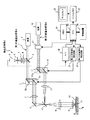
走査型レーザ顕微鏡は、第1のレーザ光源1からのレーザ光を標本17の焦点面上を走査する観察用の第1の走査光学系Aと、第2のレーザ光源10から出力されるレーザ光を標本の任意の位置に照射してケージド試薬を開裂させるための第2の走査光学系Bとを備えている。第2の走査光学系Bは標本の特定部位に特異現象を発現させる光学系である。
The scanning laser microscope includes a first scanning optical system A for observation that scans the focal plane of the specimen 17 with laser light from the first
第1の走査光学系Aは、第1のレーザ光源1、ダイクロイックミラー2、第1の走査光学ユニット3、リレーレンズ4及びミラー5から構成される。更に第1の走査光学系Aのダイクロイックミラー2の分岐光路上には、検出光学系Cが配置されている。この検出光学系Cは、測光フィルタ6、レンズ7、共焦点ピンホール8及び光電変換素子9により構成される。
The first scanning optical system A includes a first
第2の走査光学系Bは、第2のレーザ光源10、CPU22と接続しているレーザ制御素子27、第2の走査光学ユニット11、リレーレンズ12及びダイクロイックミラー13から構成される。なお、レーザ制御素子27としては、NDフィルタ(光量調整フィルタ)、AOTF(音響光学素子)やレーザシャッタ等が使用できる。
The second scanning optical system B includes a second
第1の走査光学系Aの光軸と、第2の走査光学系Bの光軸とは、ダイクロイックミラー13により合成され、結像レンズ14、対物レンズ15に導かれる。また、リレーレンズ4およびリレーレンズ12の焦点位置は、結像レンズ14の焦点位置と一致するように配置されている。標本17はステージ18上に載置されている。
The optical axis of the first scanning optical system A and the optical axis of the second scanning optical system B are combined by the
ダイクロイックミラー13は、第1の走査光学系Aからのレーザ光の波長より長波長の光を透過すると共に、第2の走査光学系Bからのレーザ光の波長を反射する特性となっている。
第1の光学走査ユニット3は、第1の走査波形発生回路20に接続されている。第2の光学走査ユニット11は、第2の走査波形発生回路21に接続されている。光電変換素子9は、A/D変換器19に接続されている。そして、第1の走査波形発生回路20、第2の走査波形発生回路21、及びA/D変換器19は、CPU(中央処理装置)22と接続している。さらに、CPU22はメモリ23に接続され、フレームメモリ25を介してディスプレイ26とも接続されている。
The
The first
CPU22は、各所に制御命令を出すもので、例えば、第1及び第2の走査光学ユニット3、11の光学スキャナ3a、3b及び11a、11bを操作制御する第1及び第2の走査波形発生回路20、21に対し、第1及び第2のレーザ光源1、10からのレーザ光が所望の領域を走査するような走査波形を指示して走査を開始させたり、A/D変換器19からのデジタルデータを画像化するなどをしている。また、後述する第2の走査光学系Bのレーザ制御素子27の制御もしている。
The
メモリ23は、A/D変換器19からのデジタルデータや、CPU22で形成される走査画像などを記憶している。ディスプレイ26は、CPU22で形成されメモリ23に記憶している走査画像をフレームメモリ25を介して表示する。
ここで、CPU22、メモリ23、フレームメモリ25等は一般的なパーソナルコンピュータ等を利用してもよい。また、後述する制御方法はコンピュータプログラムにより処理可能で、その処理プログラムはCD−ROM等の記録媒体やハードディスク等の記憶装置24に記録されている。また、通信ネットワーク経由で処理プログラムを読み出すようにしてもよい。
The
Here, a general personal computer or the like may be used for the
必要に応じて前記パーソナルコンピュータのメモリ23上に前記処理プログラムを読み出し、CPU22により実行しパーソナルコンピュータに接続されている各装置を制御している。
次に、このように構成した走査型レーザ顕微鏡の作用を説明する。第1のレーザ光源1からのレーザ光は、第1の走査波形発生回路20により走査制御される第1の走査光学ユニット3へ導かれ、任意の方向に偏向走査される。このレーザ光はさらに、リレーレンズ4、ミラー5、ダイクロイックミラー13、結像レンズ14、対物レンズ15を介して、標本17の断面16上に集光され、断面16内を2次元走査する。
If necessary, the processing program is read onto the
Next, the operation of the scanning laser microscope configured as described above will be described. The laser light from the first
標本17には第1のレーザ光源1の波長によって励起される蛍光指示薬が導入されており、断面16内をレーザ光が走査することにより、蛍光指示薬が励起されて蛍光を生じる。対物レンズ15により捕らえられた蛍光は、上記レーザ光と同じ光路を逆向きに進み、対物レンズ15、結像レンズ14、ダイクロイックミラー13を透過し、ミラー5、リレーレンズ4、第1の走査光学ユニット3を介してダイクロイックミラー2へ導かれる。
A fluorescent indicator that is excited by the wavelength of the first
ダイクロイックミラー2は、第1のレーザ光源1からのレーザ光の波長より長波長側の光を反射する特性となっており、これにより上記蛍光はダイクロイックミラー2により反射され、検出光学系Cへ導入される。
検出光学系Cにおいて、蛍光は測光フィルタ6により特定の波長の光が選択透過され、さらにレンズ7、共焦点ピンホール8により断面16からの光のみが選択されて、光電変換素子9へ入射する。
光電変換素子9からの出力信号は、A/D変換器19へ導かれ、走査制御に同期してデジタル信号に変換され、CPU22により、フレームメモリ25を介して、走査位置に対応してディスプレイ26上に表示される。表示された画像は、断面16での蛍光画像(蛍光輝度の2次元分布)、すなわち所望のイオン濃度の断面16内での分布を示している。
The
In the detection optical system C, light having a specific wavelength is selectively transmitted by the photometric filter 6 and only light from the
An output signal from the photoelectric conversion element 9 is guided to the A /
一方、第2のレーザ光源10からのレーザ光は、CPU22により制御されるレーザ制御素子27によりレーザ強度等が調整され、第2の走査光学ユニット11、リレーレンズ12、ダイクロイックミラー13を介して第1の走査光学系Aからの光軸と合成される。そして、結像レンズ14、対物レンズ15を透過して、標本17の断面16上に照射される。この時の断面16内での照射位置は、CPU22により第2の走査光学ユニット11を制御することで第1の走査光学系Aの走査位置に依存しない任意の位置を選択することができる。
On the other hand, the laser intensity of the laser light from the second
このように第2のレーザ光源10からのレーザ光が、ケージド試薬を導入した標本17に照射されると、照射された部位のケージド試薬のケージド基が開裂し、内部に包含されている物質が放出される。この放出による標本17内の上記イオン濃度分布の変化を、上記第1の走査光学系Aにより得られる画像により測定できる。
In this way, when the laser beam from the second
次に、第1の走査光学系Aの標本17への走査と、第2の走査光学系Bからの標本17へのレーザ光の照射の制御について説明する。図1にも示すように、第1及び第2の走査光学ユニット3及び11は、2つの光学スキャナ3a、3b及び11a、11bを備えている。
Next, scanning of the first scanning optical system A onto the specimen 17 and control of irradiation of the laser beam onto the specimen 17 from the second scanning optical system B will be described. As also shown in FIG. 1, the first and second scanning
CPU22は、第1の走査光学ユニット3の光学スキャナ3a、3bを走査制御する第1の走査波形発生回路20と、第2の走査光学ユニット11内の光学スキャナ11a,11bを走査制御する第2の走査波形発生回路21に接続している。
CPU22は蛍光画像を得るため、第1の走査波形発生回路20に対して目的とする断面16内の目的とする範囲を第1のレーザ光源1からのレーザ光が走査するような走査波形を指示して走査制御を開始する。また、これと共に、ケージド試薬を開裂させる所望の領域を第2のレーザ光源10からのレーザ光が走査するように第2の走査波形発生回路21に対して走査波形を指示する。
The
In order to obtain a fluorescent image, the
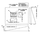
図2は、本実施形態における走査波形と走査の関係を示す。同図において、34は第1の走査光学系の走査領域を示しており、この第1の走査光学系の走査領域34の水平方向をX1、垂直方向をY1で表す。また、走査波形30はX1方向の走査波形(1波形の長さをLx1で表す)を示しており、走査波形31はY1方向の走査波形(1波形の長さをLy1で表す)で示している。
FIG. 2 shows the relationship between the scanning waveform and scanning in this embodiment. In the figure,
また、35は第2の走査光学系の走査領域を示しており、この第2の走査光学系の走査領域35の水平方向をX2、垂直方向をY2で表す。また、走査波形32はX2方向の走査波形(1波形の長さをLx2で表す)を示しており、走査波形33はY2方向の走査波形(1波形の長さをLy2で表す)で示している。
Reference numeral 35 denotes a scanning area of the second scanning optical system. The horizontal direction of the scanning area 35 of the second scanning optical system is represented by X2, and the vertical direction is represented by Y2. Further, the
また、第1の走査光学系のピクセルクロックをC1、第2の走査光学系のピクセルクロックをC2で表す。36は第2の走査光学系の走査開始位置(xo2,yo2)を示している。
さて、CPU22により走査開始が指示された第1の走査波形発生回路20は、第1の走査光学ユニット3内の2つの光学スキャナ3a、3bに対し、CPU22により指示された走査波形30,31をそれぞれ出力する。なお、ここでは光学スキャナ3aが水平方向の主走査を、光学スキャナ3bが垂直方向の副走査を行うものである。
Further, the pixel clock of the first scanning optical system is represented by C1, and the pixel clock of the second scanning optical system is represented by C2.
The first scanning
これによりレーザ光が断面16内で2次元走査を始める。第1の走査波形発生回路20は走査波形30,31の出力を始めると、A/D変換器19に対して、図示しない各種同期信号(クロック信号、垂直同期信号、水平同期信号)を出力する。A/D変換器19はこれらの各種同期信号のうち、各画素ごとに発生するクロック信号(図2に示す第1の走査光学系のピクセルクロックC1)により光電変換素子9から出力される蛍光輝度信号をA/D変換する。
As a result, the laser beam starts two-dimensional scanning within the
そして、CPU22において、A/D変換器19より得られたデジタルデータと、垂直同期信号と、水平同期信号とからメモリ23上に画像を形成して、フレームメモリ25を介してディスプレイ26上に表示する。この場合、垂直同期信号の1サイクル分が1枚の画像となる。
Then, the
このようにして得られた画像は、ケージド試薬が開裂する前における標本17内のイオン濃度分布の初期状態を示す画像となる。かかる画像を1枚ないし複数枚測定した後、CPU22は、第1の走査波形発生回路20に対して走査開始を指示し、画像の取得を開始する。続いて、CPU22は、所望のタイミングでレーザ制御素子27にレーザ強度等を指示すると共に、第2の走査波形発生回路21に走査開始を指示する。
The image thus obtained is an image showing the initial state of the ion concentration distribution in the specimen 17 before the caged reagent is cleaved. After measuring one or a plurality of such images, the
CPU22により走査開始が指示された第2の走査波形発生回路21は、第2の走査光学ユニット11内の2つの光学スキャナ11a、11bに対し、CPU22により指示された走査波形32、33をそれぞれ出力する。なお、ここでは光学スキャナ11aが水平方向の主走査を、光学スキャナ11bが垂直方向の副走査を行うものである。
The second scanning
第2の走査光学系Bからのレーザ光を標本17に照射するとケージド試薬が開裂し、これ以降に第1の走査光学系Aの走査から得られる走査画像は、ケージド試薬が開裂したことによる標本内の変化を示すものとなる。
このとき、第1の走査光学系Aの走査と第2の走査光学系Bの走査が重なる領域では、レーザ制御素子27によりレーザ強度等を調整して、レーザ光を同じ領域に同時に照射しないようにする。通常、第1の走査光学系の走査と第2の走査光学系の走査を非同期で開始すると、走査領域内のある領域でレーザ光が同時に照射される可能性がある。本発明では、各走査光学系の走査が重なる領域を、第1の走査光学系が走査している間、第2の走査光学系のレーザ光の照射を停止するようにする。
When the specimen 17 is irradiated with the laser beam from the second scanning optical system B, the caged reagent is cleaved, and the scanning image obtained from the scanning of the first scanning optical system A thereafter is a specimen obtained by cleaving the caged reagent. It shows the change within.
At this time, in the region where the scanning of the first scanning optical system A and the scanning of the second scanning optical system B overlap, the laser intensity is adjusted by the
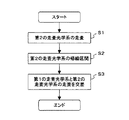
ここで、図2のような走査波形を用いて走査をする場合を例にして、第1の走査光学系の走査と第2の走査光学系の走査が重なる領域のレーザ光の照射制御について、図3を用いて説明する。図3は、1枚の画像を取得する場合の流れであり、複数枚の画像を取得する場合はこの流れを繰り返す。 Here, taking as an example a case where scanning is performed using a scanning waveform as shown in FIG. 2, with respect to irradiation control of laser light in a region where scanning of the first scanning optical system and scanning of the second scanning optical system overlap, This will be described with reference to FIG. FIG. 3 shows a flow when acquiring one image, and this flow is repeated when acquiring a plurality of images.
まず、走査領域34に対する第1の走査光学系の走査を開始する(S31)。続いて、所望のタイミングで走査領域35に対する第2の走査光学系の走査を開始する(S32)。なお、このとき第2の走査光学系のレーザ光の照射も同時に開始する。
第1の走査光学系の垂直方向の走査位置がyo2に到達したら(S33)、第2の走査光学系のレーザ光の照射を停止する(S37)。次に第1の走査光学系の垂直方向の走査位置がyo2+Y2+1に到達したら(S34)、第2の走査光学系のレーザ光の照射を再開する(S38)。これらにより、第1の走査光学系の垂直方向の走査位置がyo2からyo2+Y2の間は第2の走査光学系のレーザ光の照射が停止されるので、同時に同じ領域にレーザ光が照射されることはない。
First, scanning of the first scanning optical system with respect to the
When the vertical scanning position of the first scanning optical system reaches yo2 (S33), the laser light irradiation of the second scanning optical system is stopped (S37). Next, when the vertical scanning position of the first scanning optical system reaches yo2 + Y2 + 1 (S34), the laser light irradiation of the second scanning optical system is resumed (S38). As a result, the laser beam irradiation of the second scanning optical system is stopped when the vertical scanning position of the first scanning optical system is between yo2 and yo2 + Y2, so that the same region is simultaneously irradiated with the laser light. There is no.
第1の走査光学系の水平方向の走査は、走査領域34の全体で繰り返されており(S35)、走査領域34の終了位置まで到達したら(S36)、1枚の画像の取得が終了となる。
上記により、複数の走査光学系を用いて、所望の領域で特異現象を発現させる時のイオン濃度分布の経時変化の測定やFRAPの実験などにおいて、各走査光学系の間のレーザ光の影響を排除することが可能となる。
The horizontal scanning of the first scanning optical system is repeated for the entire scanning region 34 (S35), and when the end position of the
As described above, the influence of the laser light between the scanning optical systems is measured in the measurement of the temporal change of the ion concentration distribution when a specific phenomenon is expressed in a desired region using a plurality of scanning optical systems or in the FRAP experiment. It becomes possible to eliminate.
上記第1の実施形態では、第2の走査光学系のレーザ光の照射を制御しているが、第1の走査光学系のレーザ光の照射を制御してもよい。この場合、レーザ制御素子27を光源1の光路側に設ける。
上記第1の実施形態では、レーザ制御素子を利用しているが、光源が固体レーザの場合は、レーザ光の射出を制御してもよい。
In the first embodiment, the laser beam irradiation of the second scanning optical system is controlled. However, the laser beam irradiation of the first scanning optical system may be controlled. In this case, the
In the first embodiment, the laser control element is used. However, when the light source is a solid-state laser, the emission of laser light may be controlled.
<第2の実施形態>
本実施形態では、第2の走査光学系の走査の帰線区間で第1の走査光学系を走査させることにより、各走査光学系の走査領域が重なり合うような場合でも、第1の走査光学系からのレーザ光と第2の走査光学系からのレーザ光が走査領域内のある1点で重なることを防止する。本実施形態では、走査型レーザ顕微鏡を用いて、標本内の特定のイオン濃度分布およびその経時変化を測定する例を説明する。
<Second Embodiment>
In the present embodiment, the first scanning optical system is scanned even when the scanning regions of the scanning optical systems overlap each other by scanning the first scanning optical system in the blanking interval of the scanning of the second scanning optical system. The laser beam from the laser beam from the second scanning optical system is prevented from overlapping at a certain point in the scanning region. In the present embodiment, an example in which a specific ion concentration distribution in a specimen and its change with time are measured using a scanning laser microscope will be described.
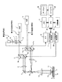
図4は、本実施形態における走査型レーザ顕微鏡のブロック図である。走査型レーザ顕微鏡は、第1のレーザ光源1からのレーザ光を標本17の焦点面上を走査する観察用の第1の走査光学系Aと、第2のレーザ光源10から出力されるレーザ光を標本の任意の位置に照射してケージド試薬を開裂させるための第2の走査光学系Bとを備えている。第2の走査光学系Bは、標本の特定部位に特異現象を発現させる光学系である。
FIG. 4 is a block diagram of the scanning laser microscope in the present embodiment. The scanning laser microscope includes a first scanning optical system A for observation that scans the focal plane of the specimen 17 with laser light from the first
第1の走査光学系Aは、第1のレーザ光源1、ダイクロイックミラー2、第1の走査光学ユニット3、リレーレンズ4、及びミラー5から構成される。更に、第1の走査光学系Aのダイクロイックミラー2の分岐光路上には、検出光学系Cが配置されている。
この検出光学系Cは、測光フィルタ6、レンズ7、共焦点ピンホール8、及び光電変換素子9により構成される。第2の走査光学系Bは、第2のレーザ光源10、第2の走査光学ユニット11、リレーレンズ12及びダイクロイックミラー13から構成される。
The first scanning optical system A includes a first
The detection optical system C includes a photometric filter 6, a lens 7, a confocal pinhole 8, and a photoelectric conversion element 9. The second scanning optical system B includes a second
第1の走査光学系Aの光軸と第2の走査光学系Bの光軸とは、ダイクロイックミラー13により合成され、結像レンズ14及び対物レンズ15に導かれる。また、リレーレンズ4およびリレーレンズ12の焦点位置は、結像レンズ14の焦点位置と一致するように配置されている。標本17はステージ18上に載置されている。
The optical axis of the first scanning optical system A and the optical axis of the second scanning optical system B are combined by the
ダイクロイックミラー13は、第1の走査光学系Aからのレーザ光の波長より長波長の光を透過すると共に、第2の走査光学系Bからのレーザ光の波長を反射する特性となっている。
第1の光学走査ユニット3は、第1の走査波形発生回路20に接続されている。第2の光学走査ユニット11は、第2の走査波形発生回路21に接続されている。光電変換素子9は、A/D変換器19に接続されている。そして、第1の走査波形発生回路20、第2の走査波形発生回路21、及びA/D変換器19は、CPU(中央処理装置)22と接続している。さらに、CPU22はメモリ23に接続され、またフレームメモリ25を介してディスプレイ26とも接続されている。
The
The first
CPU22は、各所に制御命令を出すもので、例えば、第1及び第2の走査光学ユニット3,11の光学スキャナ3a,3b及び11a,11bを操作制御する第1及び第2の走査波形発生回路20,21に対し、第1及び第2のレーザ光源1,10からのレーザ光が所望の領域を走査するような走査波形を指示して走査を開始させたり、A/D変換器19からのデジタルデータを画像化するなどをしている。また、後述する第1の走査光学系の走査開始と第2の走査光学系の走査開始の間の遅延時間も計算している。
The
メモリ23は、A/D変換器19からのデジタルデータや、CPU22で形成される走査画像などを記憶している。ディスプレイ26は、CPU22で形成されメモリ23に記憶している走査画像を、フレームメモリ25を介して表示する。
ここで、CPU22、メモリ23、フレームメモリ25等は一般的なパーソナルコンピュータ等を利用してもよい。また、後述する制御方法はコンピュータプログラムにより処理可能で、その処理プログラムはCD−ROM等の記録媒体やハードディスク等の記憶装置24に記録されている。また、通信ネットワーク経由で処理プログラムを読み出すようにしてもよい。
The
Here, a general personal computer or the like may be used for the
必要に応じてこのパーソナルコンピュータのメモリ23上に前記処理プログラムを読み出し、CPU22により実行しパーソナルコンピュータに接続されている各装置を制御している。
次に、このように構成した走査型レーザ顕微鏡の作用を説明する。第1のレーザ光源1からのレーザ光は、第1の走査波形発生回路20により走査制御される第1の走査光学ユニット3へ導かれ、任意の方向に偏向走査される。このレーザ光はさらに、リレーレンズ4、ミラー5、ダイクロイックミラー13、結像レンズ14、対物レンズ15を介して、標本17の断面16上に集光され、断面16内を2次元走査する。
If necessary, the processing program is read onto the
Next, the operation of the scanning laser microscope configured as described above will be described. The laser light from the first
標本17には第1のレーザ光源1の波長によって励起される蛍光指示薬が導入されており、断面16内をレーザ光が走査することにより、蛍光指示薬が励起されて蛍光を生じる。対物レンズ15により捕らえられた蛍光は、上記レーザ光と同じ光路を逆向きに進み、対物レンズ15、結像レンズ14、ダイクロイックミラー13を透過し、ミラー5、リレーレンズ4、第1の走査光学ユニット3を介してダイクロイックミラー2へ導かれる。
A fluorescent indicator that is excited by the wavelength of the first
ダイクロイックミラー2は、第1のレーザ光源1からのレーザ光の波長より長波長側の光を反射する特性となっており、これにより上記蛍光はダイクロイックミラー2により反射され、検出光学系Cへ導入される。
検出光学系Cにおいて、蛍光は測光フィルタ6により特定の波長の光が選択透過され、さらにレンズ7、共焦点ピンホール8により断面16からの光のみが選択されて、光電変換素子9へ入射する。
The
In the detection optical system C, light having a specific wavelength is selectively transmitted by the photometric filter 6 and only light from the
光電変換素子9からの出力信号は、A/D変換器19へ導かれ、走査制御に同期してディジタル信号に変換され、CPU22により、フレームメモリ25を介して、走査位置に対応してディスプレイ26上に表示される。表示された画像は、断面16での蛍光画像(蛍光輝度の2次元分布)、すなわち所望のイオン濃度の断面16内での分布を示している。
An output signal from the photoelectric conversion element 9 is guided to the A /
一方、第2のレーザ光源10からのレーザ光は、第2の走査光学ユニット11、リレーレンズ12、ダイクロイックミラー13を介して第1の走査光学系Aからの光軸と合成される。そして、結像レンズ14、対物レンズ15を透過して、標本17の断面16上に照射される。この時の断面16内での照射位置は、CPU22により第2の走査光学ユニット11を制御することで、第1の走査光学系Aの走査位置に依存しない任意の位置を選択することができる。
On the other hand, the laser light from the second
このように第2のレーザ光源10からのレーザ光が、ケージド試薬を導入した標本17に照射されると、照射された部位のケージド試薬のケージド基が開裂し、内部に包含されている物質が放出される。この放出による標本17内の上記イオン濃度分布の変化を、上記第1の走査光学系Aにより得られる画像により測定できる。
In this way, when the laser beam from the second
次に、第1の走査光学系Aの標本17への走査と、第2の走査光学系Bからの標本17へのレーザ光の照射の制御について説明する。図4にも示すように、第1及び第2の走査光学ユニット3及び11は、2つの光学スキャナ3a,3b及び11a,11bを備えている。
Next, scanning of the first scanning optical system A onto the specimen 17 and control of irradiation of the laser beam onto the specimen 17 from the second scanning optical system B will be described. As shown in FIG. 4, the first and second scanning
CPU22は、第1の走査光学ユニット3の光学スキャナ3a,3bを操作制御する第1の走査波形発生回路20と、第2の走査光学ユニット11内の光学スキャナ11a,11bを操作制御する第2の走査波形発生回路21に接続している。
CPU22は、蛍光画像を得るために、目的とする断面16内の目的とする範囲を第1のレーザ光源1からのレーザ光が走査するような走査波形を、第1の走査波形発生回路20に対して指示して走査制御を開始する。また、CPU22は、ケージド試薬を開裂させる所望の領域を第2のレーザ光源10からのレーザ光が走査するように第2の走査波形発生回路21に対して走査波形を指示する。
The
The
図2は、本実施形態における走査波形と走査の関係を示す。同図において、34は第1の走査光学系の走査領域を示しており、この第1の走査光学系の走査領域34の水平方向をX1、垂直方向をY1で表す。また、走査波形30はX1方向の走査波形(1波形の長さをLx1で表す)を示しており、走査波形31はY1方向の走査波形(1波形の長さをLy1で表す)を示している。
FIG. 2 shows the relationship between the scanning waveform and scanning in this embodiment. In the figure,
また、35は第2の走査光学系の走査領域を示しており、この第2の走査光学系の走査領域35の水平方向をX2、垂直方向をY2で表す。また、走査波形32はX2方向の走査波形(1波形の長さをLx2で表す)を示しており、走査波形33はY2方向の走査波形(1波形の長さをLy2で表す)を示している。
Reference numeral 35 denotes a scanning area of the second scanning optical system. The horizontal direction of the scanning area 35 of the second scanning optical system is represented by X2, and the vertical direction is represented by Y2. Further, the
また、第1の走査光学系のピクセルクロックをC1、第2の走査光学系のピクセルクロックをC2で表す。36は第2の走査光学系の走査開始位置(xo2,yo2)を示している。
さて、CPU22により走査開始が指示された第1の走査波形発生回路20は、第1の走査光学ユニット3内の2つの光学スキャナ3a,3bに対し、CPU22により指示された走査波形30,31をそれぞれ出力する。なお、ここでは光学スキャナ3aが水平方向の主走査を、光学スキャナ3bが垂直方向の副走査を行うものである。
Further, the pixel clock of the first scanning optical system is represented by C1, and the pixel clock of the second scanning optical system is represented by C2.
The first scanning
これによりレーザ光が断面16内で2次元走査を始める。第1の走査波形発生回路20は走査波形30,31の出力を始めると、A/D変換器19に対して、図示しない各種同期信号(クロック信号、垂直同期信号、水平同期信号)を出力する。A/D変換器19はこれらの各種同期信号のうち、各画素ごとに発生するクロック信号(図2に示す第1の走査光学系のピクセルクロックC1)により光電変換素子9から出力される蛍光輝度信号をA/D変換する。
As a result, the laser beam starts two-dimensional scanning within the
そして、CPU22において、A/D変換器19より得られたデジタルデータと、垂直同期信号と、水平同期信号とからメモリ23上に画像を形成して、フレームメモリ25を介してディスプレイ26上に表示する。この場合、垂直同期信号の1サイクル分が1枚の画像となる。
Then, the
このようにして得られた画像は、ケージド試薬が開裂する前における標本17内のイオン濃度分布の初期状態を示す画像となる。かかる画像を1枚ないし複数枚測定した後、CPU22は、第1の走査波形発生回路20に対して走査開始を指示し、画像の取得を開始する。続いて、後述する方法で計算した遅延時間後に、CPU22は、第2の走査波形発生回路21に走査開始を指示する。
The image thus obtained is an image showing the initial state of the ion concentration distribution in the specimen 17 before the caged reagent is cleaved. After measuring one or a plurality of such images, the
CPU22により走査開始が指示された第2の走査波形発生回路21は、第2の走査光学ユニット11内の2つの光学スキャナ11a,11bに対し、CPU22により指示された走査波形32,33をそれぞれ出力する。なお、ここでは光学スキャナ11aが水平方向の主走査を、光学スキャナ11bが垂直方向の副走査を行うものである。
The second scanning
第2の走査光学系Bからのレーザ光を標本17に照射するとケージド試薬が開裂し、これ以降に第1の走査光学系Aの走査から得られる走査画像は、ケージド試薬が開裂したことによる標本内の変化を示すものとなる。
ここで、図2のような走査波形を用いて走査をする場合を例にして、第1の走査光学系の走査開始時間に対する第2の走査光学系の走査開始時間の遅延時間について説明する。通常、第1の走査光学系の走査と第2の走査光学系の走査を非同期で開始すると、走査領域内のある1点でレーザ光が重なる可能性がある。本実施形態では、その1点が第2の走査光学系の走査の水平または垂直の帰線区間になるように、第1の走査光学系の走査開始時間または第2の走査光学系の走査開始時間を遅延させる。
When the specimen 17 is irradiated with the laser beam from the second scanning optical system B, the caged reagent is cleaved, and the scanning image obtained from the scanning of the first scanning optical system A thereafter is a specimen obtained by cleaving the caged reagent. It shows the change within.
Here, the delay time of the scanning start time of the second scanning optical system with respect to the scanning start time of the first scanning optical system will be described by taking as an example the case of scanning using the scanning waveform as shown in FIG. Normally, when the scanning of the first scanning optical system and the scanning of the second scanning optical system are started asynchronously, there is a possibility that the laser beams overlap at a certain point in the scanning region. In the present embodiment, the scanning start time of the first scanning optical system or the scanning start of the second scanning optical system is set so that one point is a horizontal or vertical blanking interval of the scanning of the second scanning optical system. Delay time.
これについて具体的に説明する。図2において、例えば走査波形32について見てみると、走査波形32の左端は急勾配になって下っており、それから緩やかに右上方へ上がって行き、その後再び急勾配で下っている。このうち、緩やかに右上方へ上がっている波形部分が、レーザ光を照射しながら走査しているところを示している。そして、この両端の急勾配の波形が帰線区間を示し、左から右への走査が再び左へ戻っていることを示す。このときレーザ光の照射は停止状態である。
This will be specifically described. In FIG. 2, for example, when looking at the
また、走査波形33について見てみると、走査波形33の左端は急勾配になって下っており、それから緩やかに右上方へ上がって行き、その後再び急勾配で下っている。このうち、緩やかに右上方へ上がっている波形部分が、レーザ光を照射しながら走査しているところを示している。そして、この両端の急勾配の波形が帰線区間を示し、上から下へ表示した走査線が再び上へ戻っていることを示す。このときレーザ光の照射は停止状態である。
Looking at the
走査波形30,31の見方についてもそれぞれ、走査波形32,33と同様である。
このとき、例えば、第2の走査光学系のレーザ光の照射が行われていない時、すなわち、第2の走査光学系の水平走査の帰線区間の時に、第1の走査光学系の走査を行うようにすれば、第1の走査光学系からのレーザ光と第2の走査光学系からのレーザ光が走査領域内のある1点で重なることはない。
The
At this time, for example, when the laser beam irradiation of the second scanning optical system is not performed, that is, during the blanking interval of the horizontal scanning of the second scanning optical system, the scanning of the first scanning optical system is performed. If performed, the laser light from the first scanning optical system and the laser light from the second scanning optical system do not overlap at one point in the scanning region.
図5は、本実施形態における第2の走査光学系の帰線区間で、第1の走査光学系の走査を行うフローを示す。まず、走査領域35を第2の走査光学系で水平走査を行う(S1)。それから、その水平走査が終わって次の走査開始まで移動する帰線区間となる(S2)。この第2の走査光学系の帰線区間で、第1の走査光学系を走査させることにより(S3)、第1の走査光学系からのレーザ光と第2の走査光学系からのレーザ光が走査領域内のある1点で重なることはない。以下では、これの実現方法を詳述する。 FIG. 5 shows a flow for scanning the first scanning optical system in the blanking interval of the second scanning optical system in the present embodiment. First, the scanning area 35 is horizontally scanned by the second scanning optical system (S1). Then, it becomes a blanking interval in which the horizontal scanning ends and moves to the start of the next scanning (S2). By scanning the first scanning optical system in the blanking section of the second scanning optical system (S3), the laser light from the first scanning optical system and the laser light from the second scanning optical system are There is no overlap at one point in the scan area. Below, the realization method of this is explained in full detail.
第2の走査光学系の水平走査の帰線区間の終点で、2つの走査光学系の走査を交差する例を説明する。なお、以下の説明中の式で、INT()は切り捨てを意味する。
まず、第2の走査光学系の走査の先頭位置(垂直位置がyo2)の走査線の先頭に、第1の走査光学系の走査が到達するまでの時間T1を次式(1)で計算する。
An example where the scanning of the two scanning optical systems intersects at the end point of the blanking interval of the horizontal scanning of the second scanning optical system will be described. In the following expression, INT () means truncation.
First, the time T1 until the scanning of the first scanning optical system reaches the head of the scanning line at the scanning start position (vertical position is yo2) of the second scanning optical system is calculated by the following equation (1). .

次に、第2の走査光学系の水平走査の1回の走査時間T2を次式(2)で計算する。 Next, one scanning time T2 of horizontal scanning of the second scanning optical system is calculated by the following equation (2).
上記T1とT2から、第2の走査光学系の走査の先頭位置に第1の走査光学系の走査が到達するまでに、第2の走査光学系が水平走査する回数naを次式(3)で計算する。 From the above T1 and T2, the number na of times the second scanning optical system performs horizontal scanning before the scanning of the first scanning optical system reaches the head position of the scanning of the second scanning optical system is expressed by the following equation (3). Calculate with
上記より、第2の走査光学系の走査の先頭位置に第1の走査光学系の走査が到達したときに、第2の走査光学系の走査の垂直位置Ys2が次式(4)で計算できる。 From the above, when the scanning of the first scanning optical system reaches the head position of the scanning of the second scanning optical system, the vertical position Ys2 of the scanning of the second scanning optical system can be calculated by the following equation (4). .
ここで、第2の走査光学系の走査の垂直位置Ys2における水平走査の帰線区間の終点で、2つの走査光学系の走査を交差するものとする。
続いて、第2の走査光学系の走査の垂直位置Ys2に第2の走査光学系の走査が到達するまでの時間Taを次式(5)で計算する。
Here, it is assumed that the scanning of the two scanning optical systems intersects at the end point of the blanking interval of the horizontal scanning at the vertical position Ys2 of the scanning of the second scanning optical system.
Subsequently, a time Ta until the scanning of the second scanning optical system reaches the vertical position Ys2 of the scanning of the second scanning optical system is calculated by the following equation (5).
次に、上記Ta時間内に第1の走査光学系の走査が到達する垂直位置Ys1を次式(6)で計算する。 Next, the vertical position Ys1 at which the scanning of the first scanning optical system reaches within the Ta time is calculated by the following equation (6).
そして、Ta時間内に各走査光学系の走査が到達した垂直位置の差Dsを次式(7)で計算する。 Then, the difference Ds between the vertical positions at which the scanning of each scanning optical system has reached within the Ta time is calculated by the following equation (7).
上記より、この垂直位置の差の時間分、第2の走査光学系の走査開始時間を第1の走査光学系の走査開始時間に対して遅延すればよい。この遅延時間tは、次式(8)で計算できる。 From the above, the scanning start time of the second scanning optical system may be delayed with respect to the scanning start time of the first scanning optical system by the time of this vertical position difference. This delay time t can be calculated by the following equation (8).
以上より、複数の走査光学系を用いて、所望の領域で特異現象を発現させる時のイオン濃度分布の経時変化の測定やFRAPの実験などにおいて、各走査光学系の間のレーザ光の影響を排除することが可能となる。
<第3の実施形態>
第2の実施形態では、水平走査を走査画像の左から右への一方向で走査しているが、走査画像の左から右と右から左の二方向すなわち往復で走査する場合もある。これは走査波形と走査の関係が図6のようになる場合である。この場合は、第2の走査光学系の垂直走査の帰線区間で、第1の走査光学系の走査と第2の走査光学系の走査を交差すればよい。
As described above, the influence of the laser light between the scanning optical systems is measured in the measurement of the temporal change of the ion concentration distribution when a specific phenomenon is expressed in a desired region using a plurality of scanning optical systems or in the FRAP experiment. It becomes possible to eliminate.
<Third Embodiment>
In the second embodiment, the horizontal scanning is performed in one direction from the left to the right of the scanned image. However, the scanning may be performed in two directions from the left to the right and from the right to the left, that is, in a reciprocal manner. This is a case where the relationship between the scanning waveform and scanning is as shown in FIG. In this case, the scanning of the first scanning optical system and the scanning of the second scanning optical system may be crossed in the blanking interval of the vertical scanning of the second scanning optical system.
図6は、本実施形態における走査波形と走査の関係を示す。同図において、図2と異なるのは、第1の走査光学系と第2の走査光学系の水平走査を往復にするために、走査波形40,42を変化させたことである。
走査波形40について見てみる。まず左から右への走査時には走査波形40は緩やかな曲線を描いて飽和に達し、折り返し後(右から左への走査時)にはこの波形を反転した波形となる。走査波形42についても同様である。
FIG. 6 shows the relationship between the scanning waveform and scanning in this embodiment. In this figure, the difference from FIG. 2 is that the
Consider the
そこで、本実施形態では、第2の走査光学系の垂直走査の帰線区間で、第1の走査光学系の走査と第2の走査光学系の走査を交差させる。
以下、第2の走査光学系の垂直走査の帰線区間で、第1の走査光学系の走査と第2の走査光学系の走査を交差する場合の遅延時間の計算を説明する。なお、以下の説明中の式で、INT()は切り捨てを意味する。
Therefore, in the present embodiment, the scanning of the first scanning optical system and the scanning of the second scanning optical system are crossed in the blanking interval of the vertical scanning of the second scanning optical system.
Hereinafter, calculation of the delay time in the case where the scanning of the first scanning optical system and the scanning of the second scanning optical system intersect in the blanking interval of the vertical scanning of the second scanning optical system will be described. In the following expression, INT () means truncation.
まず、第2の走査光学系の1回のXY走査の終了位置に、第1の走査光学系の走査が到達するまでの時間Tr1を次式(9)で計算する。 First, the time Tr1 until the scanning of the first scanning optical system reaches the end position of one XY scanning of the second scanning optical system is calculated by the following equation (9).
次に、第2の走査光学系の1回のXY走査の走査時間Tr2を次式(10)で計算する。 Next, the scanning time Tr2 for one XY scan of the second scanning optical system is calculated by the following equation (10).
上記Tr1とTr2から、第2の走査光学系の走査の終了位置に第1の走査光学系の走査が到達するまでに、第2の走査光学系がXY走査する回数nrを次式(11)で計算する。 The number nr of times the second scanning optical system performs XY scanning from the above Tr1 and Tr2 until the scanning of the first scanning optical system reaches the scanning end position of the second scanning optical system is expressed by the following equation (11). Calculate with
上記より、第2の走査光学系の走査の終了位置に(nr+1)回目の第2の走査光学系の走査が到達するまでの時間Trを次式(12)で計算する。 From the above, the time Tr until the (nr + 1) -th scanning of the second scanning optical system reaches the scanning end position of the second scanning optical system is calculated by the following equation (12).
続いて、上記Tr時間内に第1の走査光学系の走査が到達する垂直位置Yr1を次式(13)で計算する。 Subsequently, the vertical position Yr1 at which the scanning of the first scanning optical system reaches within the Tr time is calculated by the following equation (13).
そして、Tr時間内に各走査光学系の走査が到達した垂直位置の差Drを次式(14)で計算する。 Then, the difference Dr between the vertical positions where the scanning of each scanning optical system has reached within the Tr time is calculated by the following equation (14).
上記より、この垂直位置の差の時間分、第2の走査光学系の走査開始時間を第1の走査光学系の走査開始時間に対して遅延すればよい。
この遅延時間trは、次式(15)で計算できる。
From the above, the scanning start time of the second scanning optical system may be delayed with respect to the scanning start time of the first scanning optical system by the time of this vertical position difference.
This delay time tr can be calculated by the following equation (15).
上記により、複数の走査光学系を用いて所望の領域で特異現象を発現させる時のイオン濃度分布の経時変化の測定やFRAPの実験などにおいて、往復走査する場合でも各走査光学系の間のレーザ光の影響を排除することが可能となる。
なお、第2及び第3の実施形態では、第2の走査光学系の帰線区間の先頭で第1の走査光学系の走査と第2の走査光学系の走査を交差しているが、第2の走査光学系の帰線区間中であればどの位置でもよい。
As described above, the laser between each scanning optical system is used even when reciprocating scanning is performed in the measurement of change over time of ion concentration distribution or the FRAP experiment when a specific phenomenon is expressed in a desired region using a plurality of scanning optical systems. It becomes possible to eliminate the influence of light.
In the second and third embodiments, the scanning of the first scanning optical system and the scanning of the second scanning optical system intersect at the head of the blanking interval of the second scanning optical system. Any position may be used as long as it is in the blanking interval of the scanning
また、第2及び第3の実施形態では、第1の走査光学系の走査領域より第2の走査光学系の走査領域が小さい場合として記載しているが、第1の走査光学系の走査領域より第2の走査光学系の走査領域が大きい場合は、第1の走査光学系の走査の帰線区間で2つの走査光学系の走査が交差するようにする。 In the second and third embodiments, the case where the scanning area of the second scanning optical system is smaller than the scanning area of the first scanning optical system is described. However, the scanning area of the first scanning optical system is described. When the scanning area of the second scanning optical system is larger, the scanning of the two scanning optical systems intersects in the blanking interval of the scanning of the first scanning optical system.
また、第2及び第3の実施形態では、第2の走査光学系の走査開始時間を第1の走査光学系の走査開始時間に対して遅延しているが、第1の走査光学系の走査開始時間を第2の走査光学系の走査開始時間に対して遅延してもよい。
また、第2の実施形態では、第1の走査光学系と第2の走査光学系の水平走査の方向は、それぞれ一方向であり、第3の実施形態では、それぞれ往復したが、これに限らず、一方の走査光学系を一方向、他方を走査光学系を往復で水平走査するようにしてもよい。
In the second and third embodiments, the scanning start time of the second scanning optical system is delayed with respect to the scanning start time of the first scanning optical system. The start time may be delayed with respect to the scan start time of the second scanning optical system.
Further, in the second embodiment, the horizontal scanning directions of the first scanning optical system and the second scanning optical system are each one direction, and in the third embodiment, they are reciprocated. Instead, one scanning optical system may be horizontally scanned in one direction and the other in the reciprocating scanning optical system.
また、第2及び第3の実施形態では、第1の走査光学系と走査光学系の走査領域の走査方向は同方向であったが、例えば一方の走査光学系を左から走査させ、他方を右から走査させるというように、逆方向で走査するようにしてもよい。このようにすることで、交差する時間が短くなり、制御に要する負担が軽減される。 In the second and third embodiments, the scanning directions of the first scanning optical system and the scanning optical system are the same direction. For example, one scanning optical system is scanned from the left and the other is scanned. You may make it scan in a reverse direction like scanning from the right. By doing in this way, the time which cross | intersects becomes short and the burden which control requires is reduced.
また、第1から第3の実施形態では、走査光学系を2つ使用したが、これに限られず、さらに複数使用しても良い。たとえば、5つの走査光学系がある場合、1つを画像取得用走査光学系とし、他の4つをフォトブリーチ用走査光学系とすることで、同時に4つの領域をフォトブリーチすることができる。これにより、様々なパターンの条件下でFRAPの実験を行うことができる。 In the first to third embodiments, two scanning optical systems are used. However, the present invention is not limited to this, and a plurality of scanning optical systems may be used. For example, when there are five scanning optical systems, four areas can be photobleached at the same time by using one as the scanning optical system for image acquisition and the other four as the scanning optical system for photobleaching. As a result, FRAP experiments can be performed under conditions of various patterns.
なお、本発明は、第1から第3の実施形態に限定されるものではなく、本発明の要旨を逸脱しない範囲内で種々変形実施可能である。 The present invention is not limited to the first to third embodiments, and various modifications can be made without departing from the scope of the present invention.
1,10 レーザ光源
2,13 ダイクロイックミラー
3,11 走査光学ユニット
4,12 リレーレンズ
5 ミラー
6 測定フィルタ
7 レンズ
8 共焦点ピンホール
9 光電変換素子
14 結像レンズ
15 対物レンズ
16 断面位置
17 標本
18 ステージ
19 A/D変換器
20,21 走査波形発生回路
22 CPU
23 メモリ
24 記憶装置
25 フレームメモリ
26 ディスプレイ
27 レーザ制御素子
DESCRIPTION OF
23
Claims (9)
前記複数の走査光学系のうち第1の走査光学系の走査と、前記複数の走査光学系のうち第2の走査光学系の走査とが重なる領域で、該第2の走査光学系のレーザ光の照射を停止する制御を行うレーザ光照射制御手段と
を備えることを特徴とする走査型レーザ顕微鏡。 A plurality of scanning optical systems;
The laser beam of the second scanning optical system in a region where the scanning of the first scanning optical system of the plurality of scanning optical systems and the scanning of the second scanning optical system of the plurality of scanning optical systems overlap. And a laser beam irradiation control means for controlling to stop irradiation of the scanning laser microscope.
前記標本の特定の部位に特異現象を発現させるための第2の走査光学系と、
前記第1の走査光学系の走査と前記第2の走査光学系の走査とが重なる領域で、第1の走査光学系または第2の走査光学系のレーザ光の照射を停止する制御を行うレーザ光照射制御手段と
を備えることを特徴とする走査型レーザ顕微鏡。 A first scanning optical system for obtaining a scanned image of the specimen;
A second scanning optical system for expressing a specific phenomenon in a specific part of the specimen;
Laser that controls to stop the irradiation of the laser light of the first scanning optical system or the second scanning optical system in a region where the scanning of the first scanning optical system and the scanning of the second scanning optical system overlap. A scanning laser microscope comprising: a light irradiation control unit.
前記複数の走査光学系のうち第1の走査光学系の走査と、前記複数の走査光学系のうち第2の走査光学系の走査とが重なる領域で、該第2の走査光学系のレーザ光の照射を停止する制御を行う
ことを特徴とする走査型レーザ顕微鏡制御方法。 A scanning laser microscope control method for controlling a scanning laser microscope provided with a plurality of scanning optical systems,
The laser beam of the second scanning optical system in a region where the scanning of the first scanning optical system of the plurality of scanning optical systems and the scanning of the second scanning optical system of the plurality of scanning optical systems overlap. A method for controlling a scanning laser microscope, characterized in that control for stopping irradiation of the laser beam is performed.
前記複数の走査光学系に走査を行わせる処理と、
前記複数の走査光学系を制御して、当該複数の走査光学系のうち第1の走査光学系の走査と、前記複数の走査光学系のうち第2の走査光学系の走査が重なる領域で、該第2の走査光学系のレーザ光の照射を停止する処理
を、コンピュータに実行させるための走査型レーザ顕微鏡制御プログラム。 A scanning laser microscope control program for causing a computer to execute control of a scanning laser microscope having a plurality of scanning optical systems,
Processing for causing the plurality of scanning optical systems to perform scanning;
By controlling the plurality of scanning optical systems, in a region where the scanning of the first scanning optical system of the plurality of scanning optical systems and the scanning of the second scanning optical system of the plurality of scanning optical systems overlap, A scanning laser microscope control program for causing a computer to execute processing for stopping irradiation of laser light of the second scanning optical system.
前記複数の走査光学系のうち第1の走査光学系の走査の帰線区間で、前記複数の走査光学系のうち第2の走査光学系の走査と該第1の走査光学系の走査とを交差させる制御を行う交差制御手段と、
を備えることを特徴とする走査型レーザ顕微鏡。 A plurality of scanning optical systems;
Of the plurality of scanning optical systems, the second scanning optical system and the first scanning optical system scan among the plurality of scanning optical systems in a blanking interval of scanning of the first scanning optical system. Crossing control means for controlling crossing;
A scanning laser microscope comprising:
前記標本の特定の部位に特異現象を発現させるための第2の走査光学系と、
前記第2の走査光学系の走査の帰線区間で、該第2の走査光学系の走査と前記第1の走査光学系の走査とを交差させる制御を行う交差制御手段と、
を備えることを特徴とする走査型レーザ顕微鏡。 A first scanning optical system for obtaining a scanned image of the specimen;
A second scanning optical system for expressing a specific phenomenon in a specific part of the specimen;
Cross control means for performing control for crossing the scanning of the second scanning optical system and the scanning of the first scanning optical system in a blanking interval of scanning of the second scanning optical system;
A scanning laser microscope comprising:
前記複数の走査光学系のうち第1の走査光学系の走査の帰線区間で、前記複数の走査光学系のうち第2の走査光学系の走査と該第1の走査光学系の走査とを交差させることを特徴とする走査型レーザ顕微鏡制御方法。 A scanning laser microscope control method for controlling a scanning laser microscope provided with a plurality of scanning optical systems,
Of the plurality of scanning optical systems, the second scanning optical system and the first scanning optical system scan among the plurality of scanning optical systems in a blanking interval of scanning of the first scanning optical system. A scanning laser microscope control method characterized by crossing.
前記複数の走査光学系に走査を行わせる処理と、
前記複数の走査光学系を制御して、当該複数の走査光学系のうち第1の走査光学系の走査の帰線区間で、前記複数の走査光学系のうち第2の走査光学系の走査と該第1の走査光学系の走査とを交差させる処理
を、コンピュータに実行させるための走査型レーザ顕微鏡制御プログラム。
A scanning laser microscope control program for causing a computer to execute control of a scanning laser microscope having a plurality of scanning optical systems,
Processing for causing the plurality of scanning optical systems to perform scanning;
Controlling the plurality of scanning optical systems to scan a second scanning optical system among the plurality of scanning optical systems in a blanking interval of scanning of the first scanning optical system among the plurality of scanning optical systems; A scanning laser microscope control program for causing a computer to execute a process of crossing the scanning of the first scanning optical system.
Priority Applications (1)
| Application Number | Priority Date | Filing Date | Title |
|---|---|---|---|
| JP2004104157A JP4694137B2 (en) | 2004-03-31 | 2004-03-31 | Scanning laser microscope, control method, and control program |
Applications Claiming Priority (1)
| Application Number | Priority Date | Filing Date | Title |
|---|---|---|---|
| JP2004104157A JP4694137B2 (en) | 2004-03-31 | 2004-03-31 | Scanning laser microscope, control method, and control program |
Publications (3)
| Publication Number | Publication Date |
|---|---|
| JP2005292273A true JP2005292273A (en) | 2005-10-20 |
| JP2005292273A5 JP2005292273A5 (en) | 2007-05-10 |
| JP4694137B2 JP4694137B2 (en) | 2011-06-08 |
Family
ID=35325300
Family Applications (1)
| Application Number | Title | Priority Date | Filing Date |
|---|---|---|---|
| JP2004104157A Expired - Fee Related JP4694137B2 (en) | 2004-03-31 | 2004-03-31 | Scanning laser microscope, control method, and control program |
Country Status (1)
| Country | Link |
|---|---|
| JP (1) | JP4694137B2 (en) |
Cited By (1)
| Publication number | Priority date | Publication date | Assignee | Title |
|---|---|---|---|---|
| JP2008216996A (en) * | 2007-02-05 | 2008-09-18 | Olympus Corp | Scanning laser microscope and observation method |
Citations (2)
| Publication number | Priority date | Publication date | Assignee | Title |
|---|---|---|---|---|
| JP2000275529A (en) * | 1999-03-24 | 2000-10-06 | Olympus Optical Co Ltd | Scanning type laser microscope |
| JP2003315681A (en) * | 2002-04-26 | 2003-11-06 | Olympus Optical Co Ltd | Microscope apparatus |
-
2004
- 2004-03-31 JP JP2004104157A patent/JP4694137B2/en not_active Expired - Fee Related
Patent Citations (2)
| Publication number | Priority date | Publication date | Assignee | Title |
|---|---|---|---|---|
| JP2000275529A (en) * | 1999-03-24 | 2000-10-06 | Olympus Optical Co Ltd | Scanning type laser microscope |
| JP2003315681A (en) * | 2002-04-26 | 2003-11-06 | Olympus Optical Co Ltd | Microscope apparatus |
Cited By (2)
| Publication number | Priority date | Publication date | Assignee | Title |
|---|---|---|---|---|
| JP2008216996A (en) * | 2007-02-05 | 2008-09-18 | Olympus Corp | Scanning laser microscope and observation method |
| US7560709B2 (en) * | 2007-02-05 | 2009-07-14 | Olympus Corporation | Scanning laser microscope |
Also Published As
| Publication number | Publication date |
|---|---|
| JP4694137B2 (en) | 2011-06-08 |
Similar Documents
| Publication | Publication Date | Title |
|---|---|---|
| JP4932076B2 (en) | Scanning laser microscope | |
| JP4468507B2 (en) | Scanning laser microscope | |
| JPH10206742A (en) | Laser scanning microscope | |
| KR100689319B1 (en) | Scanning Confocal Microscope | |
| US20050280818A1 (en) | Confocal observation system | |
| JP4700299B2 (en) | Confocal scanning microscope | |
| EP1681589A1 (en) | Scanning microscope and specimen image obtaining method | |
| JP6253395B2 (en) | Image generation system | |
| JP2002098901A (en) | Scanning laser microscope | |
| JP2005301065A (en) | Observation device | |
| JP6177000B2 (en) | Laser scanning microscope | |
| JP4136440B2 (en) | Microscope equipment | |
| JP4694137B2 (en) | Scanning laser microscope, control method, and control program | |
| JP5052009B2 (en) | Scanning microscope and specimen image acquisition method | |
| JP4885439B2 (en) | Color image acquisition method and confocal laser microscope | |
| JP4963543B2 (en) | Scanning laser microscope and control method thereof | |
| JP2005345764A (en) | Scanning optical device | |
| JP2006003805A (en) | Confocal observation system, photoirradiation method and photoirradiation program | |
| JP2011237616A (en) | Scanning microscope | |
| JP5892424B2 (en) | Image acquisition method, image acquisition device, and scanning microscope | |
| JP2004212204A (en) | Fluorescence microscope, measuring method of fluorescent lifetime, and measuring program of fluorescent lifetime | |
| JP7754932B2 (en) | Sample observation device and sample observation method | |
| JP5655434B2 (en) | Observation apparatus and observation method | |
| JP4468642B2 (en) | Confocal laser scanning microscope apparatus and sample information recording method | |
| JP2007309776A (en) | Microscope apparatus and cell observation method |
Legal Events
| Date | Code | Title | Description |
|---|---|---|---|
| A521 | Written amendment |
Free format text: JAPANESE INTERMEDIATE CODE: A523 Effective date: 20070320 |
|
| A621 | Written request for application examination |
Free format text: JAPANESE INTERMEDIATE CODE: A621 Effective date: 20070320 |
|
| A977 | Report on retrieval |
Free format text: JAPANESE INTERMEDIATE CODE: A971007 Effective date: 20100706 |
|
| A131 | Notification of reasons for refusal |
Free format text: JAPANESE INTERMEDIATE CODE: A131 Effective date: 20100720 |
|
| A521 | Written amendment |
Free format text: JAPANESE INTERMEDIATE CODE: A523 Effective date: 20100916 |
|
| TRDD | Decision of grant or rejection written | ||
| A01 | Written decision to grant a patent or to grant a registration (utility model) |
Free format text: JAPANESE INTERMEDIATE CODE: A01 Effective date: 20110208 |
|
| A01 | Written decision to grant a patent or to grant a registration (utility model) |
Free format text: JAPANESE INTERMEDIATE CODE: A01 |
|
| A61 | First payment of annual fees (during grant procedure) |
Free format text: JAPANESE INTERMEDIATE CODE: A61 Effective date: 20110223 |
|
| FPAY | Renewal fee payment (event date is renewal date of database) |
Free format text: PAYMENT UNTIL: 20140304 Year of fee payment: 3 |
|
| R151 | Written notification of patent or utility model registration |
Ref document number: 4694137 Country of ref document: JP Free format text: JAPANESE INTERMEDIATE CODE: R151 |
|
| S531 | Written request for registration of change of domicile |
Free format text: JAPANESE INTERMEDIATE CODE: R313531 |
|
| R350 | Written notification of registration of transfer |
Free format text: JAPANESE INTERMEDIATE CODE: R350 |
|
| R250 | Receipt of annual fees |
Free format text: JAPANESE INTERMEDIATE CODE: R250 |
|
| LAPS | Cancellation because of no payment of annual fees |