JP2005292099A - Tree diagnosis method and apparatus - Google Patents
Tree diagnosis method and apparatus Download PDFInfo
- Publication number
- JP2005292099A JP2005292099A JP2004130462A JP2004130462A JP2005292099A JP 2005292099 A JP2005292099 A JP 2005292099A JP 2004130462 A JP2004130462 A JP 2004130462A JP 2004130462 A JP2004130462 A JP 2004130462A JP 2005292099 A JP2005292099 A JP 2005292099A
- Authority
- JP
- Japan
- Prior art keywords
- tree
- radio wave
- intensity
- transmission
- radiated
- Prior art date
- Legal status (The legal status is an assumption and is not a legal conclusion. Google has not performed a legal analysis and makes no representation as to the accuracy of the status listed.)
- Pending
Links
Images


Landscapes
- Monitoring And Testing Of Transmission In General (AREA)
Abstract
【目的】 植えられている状態での樹木の葉の育成状態をそのまま診断する方法及び装置を提供する。
【構成】 送信アンテナ12から放射された放射電波は、おもに樹木100により吸収されるため、受信アンテナ31A、31B、31C、31Dに到達する透過電波22の強度は、放射電波21の強度に対して減少する。この減少量が透過損失である。この透過損失は主に樹木の水分による吸収損失で決まるため水分の吸収に起因する透過損失の測定から樹木100の育成状態が診断可能となる。そのためには、樹木に電波を照射するための放射電波と、放射電波が樹木を透過した後の透過電波の強度比から透過損失を算出し、さらに透過損失の標準偏差値から樹木の脱水率を算出し、樹木の診断を行う。
【選択図】 図1[Objective] To provide a method and an apparatus for directly diagnosing the growing state of leaves of a tree in a planted state.
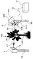
[Configuration] Since the radiated radio wave radiated from the transmitting antenna 12 is mainly absorbed by the tree 100, the intensity of the transmitted radio wave 22 reaching the receiving antennas 31A, 31B, 31C, and 31D is higher than the intensity of the radiated radio wave 21. Decrease. This decrease is the transmission loss. Since this transmission loss is mainly determined by the absorption loss due to the moisture of the tree, the growth state of the tree 100 can be diagnosed from the measurement of the transmission loss due to the absorption of the moisture. For that purpose, the transmission loss is calculated from the intensity ratio of the radiated radio wave to irradiate the tree with the radio wave and the transmitted radio wave after the radiated radio wave passes through the tree, and the dehydration rate of the tree is calculated from the standard deviation value of the transmission loss. Calculate and diagnose trees.
[Selection] Figure 1
Description
本発明は、電波を樹木に照射し、樹木を透過した電波の強度を検出することにより樹木を診断する樹木診断方法及び装置に関するものであり、特に樹木による電波の透過損失を検出し、樹木に含まれる水分の脱水率を算出することにより樹木の健康状態を診断する樹木診断方法及び装置に関する。 The present invention relates to a tree diagnosis method and apparatus for diagnosing a tree by irradiating a tree with radio waves and detecting the intensity of the radio wave transmitted through the tree, and particularly detects a transmission loss of radio waves caused by the tree. The present invention relates to a tree diagnosis method and apparatus for diagnosing the health state of a tree by calculating a dehydration rate of contained water.
樹木の健康状態の把握は、街路樹や山林の管理には必須である。健康状態の良い樹木は葉、幹に十分な水分量を保持するため、葉、幹の水分量の定量的な把握により樹木の健康状態の診断は可能であり。水分量を定量的に把握するには、採取した樹木の採取部分の重量を計測し、次に加熱などにより水分を殆んどゼロとし再び重量を計測し、重量の差分を求める方法が一般的である。この他、電波を樹木に照射する樹木診断方法がある。この方法は、樹木の水分量を健康状態を保ちながら計測することができるため、樹木の診断方法としては極めて有効な方法である。 Understanding the health of trees is essential for managing roadside trees and forests. Trees with good health retain sufficient water content in their leaves and trunks, so it is possible to diagnose the health of trees by quantitatively grasping their water content. In order to quantitatively grasp the amount of water, it is common to measure the weight of the harvested portion of the collected tree, then measure the weight again with heating to almost zero and then determine the difference in weight. It is. In addition, there is a tree diagnosis method for irradiating trees with radio waves. This method is extremely effective as a method for diagnosing a tree because the moisture content of the tree can be measured while maintaining a healthy state.
この樹木診断方法は、樹木の幹の部分の水分量を計測する方法として既に特許文献1に提案されている。特許文献1に提案されている方法は、伐採した木材を、電波を放射する送信アンテナと電波を受信する受信アンテナで挟み、木材を透過した電波の受信信号レベルを計測するとともに、木材の重量を計測し水分量を算出するものである。 This tree diagnosis method has already been proposed in
しかし、これらの樹木診断方法は伐採された樹木を対象としており、植えられている状態での樹木の葉の健康状態をそのまま診断する方法はこれまで提案されていなかった。 However, these tree diagnosis methods target felled trees, and no method has been proposed for diagnosing the health condition of the leaves of the trees as they are planted.
本発明は、樹木の葉の健康状態を植えられている状態で診断する方法及び装置を提供することを目的とする。 An object of this invention is to provide the method and apparatus which diagnose the health state of the leaf of a tree in the planted state.
上述の課題を解決し目的を達成するため、この発明に係わる樹木診断方法は、請求項1の記載によれば、樹木に電波を照射して樹木の健康状態を診断する樹木診断方法において、送信装置により放射した放射電波の強度を受信装置により計測する第1の計測工程と、前記送信装置により放射した前記放射電波が前記樹木を透過した透過電波の強度を前記受信装置により計測する第2の計測工程と、信号処理装置により前記第1の計測工程で計測された前記放射電波の強度の計測値と、前記第2の計測工程で計測された前記透過電波の強度の計測値とから強度比を算出する信号処理工程とにより樹木の健康状態を診断することを特徴とする。 In order to solve the above-described problems and achieve the object, a tree diagnosis method according to the present invention is the tree diagnosis method according to
上述の課題を解決し目的を達成するため、この発明に係わる樹木診断方法は、請求項2の記載によれば、前記第2の計測工程は、前記樹木の複数箇所の前記透過電波の強度を計測することを特徴とする。 In order to solve the above-described problems and achieve the object, according to the tree diagnosis method of the present invention, the second measurement step includes calculating the intensity of the transmitted radio waves at a plurality of locations of the tree. It is characterized by measuring.
上述の課題を解決し目的を達成するため、この発明に係わる樹木診断方法は、請求項3の記載によれば、前記第1の計測工程は、前記送信装置を移動させる第1の移動工程を含むことを特徴とする。In order to solve the above-described problems and achieve the object, according to the tree diagnosis method of the present invention, the first measurement step includes a first movement step of moving the transmission device. It is characterized by including.
上述の課題を解決し目的を達成するため、この発明に係わる樹木診断方法は、請求項4の記載によれば、前記第2の計測工程は、前記受信装置を移動させる第2の移動工程を含むことを特徴とする。 In order to solve the above-described problems and achieve the object, according to the tree diagnosis method of the present invention, the second measuring step includes a second moving step of moving the receiving device. It is characterized by including.
上述の課題を解決し目的を達成するため、この発明に係わる樹木診断方法は、請求項5の記載によれば、前記信号処理工程は、前記第1の計測工程で計測された前記放射電波の強度の計測値を記憶する基準受信信号記憶工程と、前記第2の計測工程で計測された前記透過電波の強度の計測値を記憶する受信信号記憶工程と、前記基準受信信号記憶工程で記憶された前記放射電波の強度の計測値と前記受信信号記憶工程で記憶された前記透過電波の強度の計測値との強度比から透過損失を算出する透過損失算出工程とを含むことを特徴とする。 In order to solve the above-mentioned problems and achieve the object, according to the tree diagnosis method of the present invention, the signal processing step includes the step of analyzing the radiated radio wave measured in the first measurement step. Stored in the reference received signal storing step for storing the measured intensity value, the received signal storing step for storing the measured intensity value of the transmitted radio wave measured in the second measuring step, and the reference received signal storing step. A transmission loss calculating step of calculating a transmission loss from an intensity ratio between the measured value of the intensity of the radiated radio wave and the measured value of the intensity of the transmitted radio wave stored in the received signal storing step.
上述の課題を解決し目的を達成するため、この発明に係わる樹木診断方法は、請求項6の記載によれば、前記信号処理工程は、複数の前記強度比の標準偏差値を算出する標準偏差値算出工程と、前記標準偏差値から脱水率を算出する脱水率算出工程と、算出された脱水率から前記樹木の健康状態を診断する樹木診断工程とを含むことを特徴とする。 In order to solve the above-mentioned problems and achieve the object, a tree diagnosis method according to the present invention is characterized in that, according to
また、上述の課題を解決し目的を達成するため、この発明に係わる樹木診断装置は、請求項7の記載によれば、樹木に電波を照射して樹木の健康状態を診断する樹木診断装置において、前記樹木に放射電波を放射する送信装置と、前記放射電波が樹木を透過した後の透過電波を受信する受信装置と、前記放射電波と前記透過電波の強度比から樹木の健康状態を診断する信号処理装置とを具備することを特徴とする。 In order to solve the above-described problems and achieve the object, a tree diagnostic apparatus according to the present invention is a tree diagnostic apparatus according to
上述の課題を解決し目的を達成するため、この発明に係わる樹木診断方法は、請求項8の記載によれば、前記受信装置は複数の受信アンテナを備え、前記受信アンテナの各々が前記透過電波を受信することを特徴とする。 In order to solve the above-described problems and achieve the object, a tree diagnosis method according to the present invention is according to
上述の課題を解決し目的を達成するため、この発明に係わる樹木診断方法は、請求項9の記載によれば、前記送信装置は複数の送信アンテナを備え、前記送信アンテナの各々が前記放射電波を放射することを特徴とする。 In order to solve the above-described problems and achieve the object, according to the tree diagnosis method of the present invention, the transmitter includes a plurality of transmission antennas, and each of the transmission antennas is the radiated radio wave. It is characterized by radiating.
上述の課題を解決し目的を達成するため、この発明に係わる樹木診断方法は、請求項10の記載によれば、前記送信装置を移動可能とする第1の移動手段をさらに備えることを特徴とする。 In order to solve the above-described problems and achieve the object, the tree diagnosis method according to the present invention further comprises a first moving means that enables the transmitter to move according to
上述の課題を解決し目的を達成するため、この発明に係わる樹木診断方法は、請求項11の記載によれば、前記受信装置を移動可能とする第2の移動手段をさらに備えることを特徴とする。 In order to solve the above-mentioned problems and achieve the object, the tree diagnosis method according to the present invention is characterized in that, according to
上述の課題を解決し目的を達成するため、この発明に係わる樹木診断方法は、請求項12の記載によれば、前記信号処理装置は、前記放射電波の強度の計測値を記憶する基準受信信号記憶部と、前記透過電波の強度の計測値を記憶する受信信号記憶部と、前記基準受信信号記憶部で記憶された前記放射電波の強度の計測値と前記受信信号記憶部で記憶された前記透過電波の強度の計測値との強度比から透過損失を算出する透過損失算出部とを備えることを特徴とする。 In order to solve the above-mentioned problems and achieve the object, a tree diagnosis method according to the present invention is characterized in that, according to
上述の課題を解決し目的を達成するため、この発明に係わる樹木診断方法は、請求項13の記載によれば、前記信号処理装置は、複数の前記強度比の標準偏差値を算出する標準偏差値算出部と、前記標準偏差値から脱水率を計算する脱水率算出部と、算出された脱水率から前記樹木の健康状態を診断する樹木診断部とを備えることを特徴とする。 In order to solve the above-described problems and achieve the object, a tree diagnosis method according to the present invention is characterized in that, according to
この発明の樹木診断装置によれば、樹木の葉の健康状態を植えられている状態で診断する方法及び装置を提供することが可能となる。 According to the tree diagnosis apparatus of the present invention, it is possible to provide a method and an apparatus for diagnosing the health condition of a tree leaf in a planted state.
以下に、この発明に係わる樹木診断方法及び装置の第1の実施例における手順について図1〜図7を参照して説明する。 Below, the procedure in the 1st Example of the tree diagnostic method and apparatus concerning this invention is demonstrated with reference to FIGS.
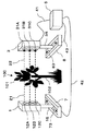
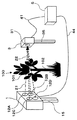
図1は第1の実施例の樹木診断装置の概略斜視図である。樹木診断装置は、送信装置1と受信装置3と受信信号ケーブル41と信号処理装置5とから構成される。送信装置1は、送信アンテナ12を装備し、支柱15により地上に固定される。受信装置2は、受信アンテナ31A、31B、31C、31Dを装備し、支柱35により地上に固定される。送信アンテナ12から放射される放射電波21は、樹木100の葉101に照射される。樹木100は葉101と幹102とから構成されるが、放射電波21は主に葉101に照射される。葉101のそれぞれ異なる部分を透過した透過電波22は受信アンテナ31A、31B、31C、31Dにより受信される。受信された信号は受信信号ケーブル41により信号処理装置5へ伝送される。 FIG. 1 is a schematic perspective view of a tree diagnostic apparatus according to the first embodiment. The tree diagnosis apparatus includes a
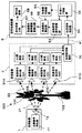
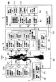
図2は第1の実施例の樹木診断装置の機能構成図である。樹木診断装置は、送信装置1と受信装置3と受信信号ケーブル41と信号処理装置5とから構成される。送信装置1は、送信信号発生部11と送信アンテナ12とから構成される。受信装置3は、受信アンテナ31A、31B、31C、31Dと、受信信号検出部32A、32B、33C、34Dと、AD変換部33A、33B、33C、33Dと、伝送信号駆動部34とから構成される。信号処理装置5は、伝送信号検出部51と、計測モード切替部52と、基準受信信号記憶部53と、受信信号記憶部54と、透過損失算出部55と、透過損失標準偏差値算出部56と、脱水率算出部57と、樹木診断部58とから構成される。 FIG. 2 is a functional configuration diagram of the tree diagnosis apparatus according to the first embodiment. The tree diagnosis apparatus includes a
送信アンテナ12から放射される放射電波21は樹木100の葉101に照射される。葉101に照射された放射電波21は、葉101を透過後、透過電波22として受信アンテナ31A、31B、31C、31Dで受信される。受信アンテナ31A、31B、31C、31Dで受信された受信信号は、受信信号検出部32A、32B、32C、32Dで検出され、さらにAD変換部33A、33B、33C、33Dによりそれぞれ4個のデジタル受信信号に変換される。デジタル信号に変換された4個のデジタル受信信号は伝送信号駆動部34から、受信信号ケーブル41を介して信号処理装置5へ送出される。 The radiated
受信信号ケーブル41により送出された4個のデジタル受信信号は、信号処理装置5の伝送信号検出部51で受信され、計測モード切替部52へ送出される。計測モード切替部52へ送出された4個のデジタル受信信号は、計測モード切替部52が基準モードの場合基準受信信号記憶部53へ、診断モードの場合受信信号記憶部54へ送出される。後に説明するように、基準モードは樹木がない場合の計測を、診断モードは樹木があり樹木診断を行う場合の計測を示す。計測モード切替部52の基準モード、診断モードの切替は別手段、例えば手動又は自動で行われる。透過損失算出部55では、受信信号記憶部54からの4個のデジタル受信信号とこれらに対応する基準受信信号記憶部53からの4個のデジタル受信信号を用いて、4個の透過損失が求められる。この4個の透過損失データから透過損失標準偏差値算出部56で透過損失の標準偏差値が算出される。さらに、この透過損失の標準偏差値から脱水率算出部57で樹木100の葉101の脱水率が算出され、この値に基づいて樹木診断部58で樹木100の葉101の健康状態の診断が行われる。なお、透過損失、透過損失の標準偏差値、脱水率の算出については後に詳細に説明する。 The four digital reception signals transmitted by the
送信アンテナ12から放射された放射電波は、おもに樹木100の葉101により反射され、吸収されるため、受信アンテナ31A、31B、31C、31Dに到達する透過電波22の強度は、放射電波21の強度に対して減少する。この減少量が透過損失である。この透過損失は主に樹木の水分による吸収損失で決まり、反射損失には殆んど依存しない。そのため、水分の吸収に起因する透過損失の測定から樹木100の健康状態が診断可能となる。すなわち、樹木の健康が順調な場合、樹木100の葉の101の水分量はある一定量保持されるが、樹木の健康状態が何らかの理由で阻害され枯れたりするとその水分量は減少する。従って、水分の抜け具合からその樹木の健康状態が診断可能となる。この水分量の変化は樹木100の幹102より葉101が著しい。そのため、樹木100の葉101の水分量を検知することによりさらに精度よく樹木の健康状態の診断ができる。 Since the radiated radio wave radiated from the transmitting
樹木100の樹木診断に必要な樹木100の葉101の透過損失は以下のように算出される。まず、計測モード切替部52を基準モードに切替える。この場合、測定のための機材は樹木診断を行う場合と同じ配置とし、測定対象物の樹木100がない場合の放射電波21を受信アンテナ31A、31B、31C、31Dで受信する。さらに受信信号検出部32A、32B、32C、32Dで検出され、AD変換部33A、33B、33C、33Dの出力として得られる放射電波の強度の計測値を基準信号記憶部53に基準値として記憶する。次に計測モード切替部52を診断モードに切替える。この場合、測定のための機材は樹木診断を行う場合の配置とし、対象物の葉101を放射電波21で照射し、照射後の透過電波22を受信アンテナ31A、31B、31C、31Dで受信する。さらに受信信号検出部32A、32B、32C、32Dで検出され、AD変換部33A、33B、33C、33Dの出力として得られる透過電波の強度の計測値を受信信号記憶部54に記憶する。樹木100の葉101の透過損失は放射電波の強度の計測値と透過電波の強度の計測値から、(放射電波の強度の計測値−透過電波の強度の計測値)/(放射電波の強度の計測値)なる式により算出される。 The transmission loss of the
受信アンテナ31A、31B、31C、31Dで受信される透過電波22は葉101のそれぞれ異なる部分を通過するため、それぞれの透過損失は異なる。これら4箇所を透過する透過電波の透過損失のばらつきは、後で説明するように、葉の枚数よりも葉に含まれる水分量に大きく依存する。透過損失のばらつきは、水分量が多く樹木の健康状態が良好な場合は大きく、水分量が少なく樹木の健康状態が悪く枯れる寸前の樹木の場合は少ない。したがって、透過損失のばらつきの大きさを標準偏差値として定量的に把握することにより、樹木100の葉101の水分量が定量的に推定でき、樹木の健康状態の診断が可能となる。 Since the transmitted
葉101の水分量は含水率或いは脱水率で調べられる。脱水率は水分が抜ける前の葉の重量から水分が抜けたあとの葉の重量の差を、水分が抜ける前の葉の重量で除した値である。脱水率0%は水分が全く抜けていない生木の状態を、100%は水分が完全に抜け切り葉101が枯れた状態を示す。そのため、脱水率は樹木100の葉101の健康状態を表す指標として適するものである。 The water content of the
次に、図3から図6により、樹木の透過損失のばらつきを標準偏差値で表現し、この標準偏差値から葉101の脱水率が算出できる原理を実験結果を用いて説明する。 Next, with reference to FIG. 3 to FIG. 6, the principle that the variation in the transmission loss of the tree is expressed by the standard deviation value and the dehydration rate of the
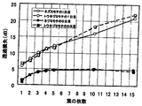
図3は、ネズミモチとトウネズミモチの葉の枚数と透過損失との関係を示す実験データである。ネズミモチは樹高5mほど、トウネズミモチは樹高12m以上で街路樹としては一般的な常緑樹である。この一般的な街路樹であるネズミモチとトウネズミモチについて、葉の枚数に対する透過損失を実験で調べた。図3は、ネズミモチ、トウネズミモチを摘み取った日を1日目とし、1日目とそのまま乾燥状態においた5日目の、葉の枚数に対する透過損失との関係を示す実験データである。図3は、葉の枚数が増加すると透過損失は増加すること、5日目の方が1日目と比べると葉の枚数に対する透過損失の増加の割合が少ないこと、この傾向はネズミモチ、トウネズミモチともほぼ同じであることを示している。 FIG. 3 is experimental data showing the relationship between the number of leaves and the transmission loss of the mouse and wilt. A mouse tree is an evergreen tree that is a typical roadside tree with a tree height of about 5 m and a tree mouse tree with a tree height of 12 m or more. In this experiment, we examined the transmission loss for the number of leaves in the common roadside trees, the mouse and the potato. FIG. 3 is experimental data showing the relationship between the transmission loss with respect to the number of leaves on the first day and the fifth day in a dry state, where the day of picking the mouse and the worm is the first day. FIG. 3 shows that transmission loss increases as the number of leaves increases, and that the rate of increase in transmission loss with respect to the number of leaves is smaller on the fifth day than on the first day. Both are almost the same.
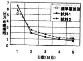
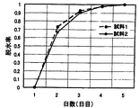
図4は、トウネズミモチの葉一枚当りの透過損失と、葉を摘み取ってからそのままの状態で乾燥させた日数との関係を示す実験データである。トウネズミモチの2枚の葉について実験を行い、その結果を試料1と試料2で示した。さらに図4のトウネズミモチの葉一枚当りの透過損失の実験結果に、図3に示すトウネズミモチの1日目と5日目の透過損失の標準偏差値を□印で併せて示した。透過損失の標準偏差値σは図3に示す葉の枚数に対する透過損失の測定値から次式により得られる。すなわち、葉の枚数nに対する透過損失の測定値をLn、測定時の葉の枚数の最大値をMとすると、
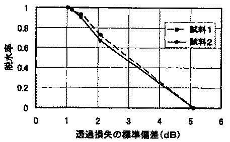
図5は、トウネズミモチの葉一枚当りの脱水率と日との関係を示す実験データである。脱水率は、1日目の1枚当りの葉の重量とそれ以降のX日目の1枚当りの葉の重量を計測し、(1日目の葉の重量−X日目の葉の重量)/(1日目の葉の重量)から求められる。 FIG. 5 is experimental data showing the relationship between the dehydration rate per leaf and the day. The dehydration rate was determined by measuring the weight of the leaf per day on the first day and the weight of the leaf per day on the X day thereafter (the weight of the leaf on the first day-the weight of the leaf on the X day). ) / (Weight of leaf on day 1).
図6は、透過損失の標準偏差値と脱水率との関係を示す図である。図6は、図4で得られる透過損失の標準偏差値と日数との関係を示す図と、図5で得られた脱水率と日数との関係を示す図から、日数をパラメータ(助変数)として求められる。図6から、脱水率は透過損失の標準偏差値に対しほぼ直線的に変化することが分かる。これにより、樹木の各部分の透過損失を計測し、その標準偏差値を求めることにより、その樹木の脱水率が得られることになる。したがって、この脱水率から樹木の健康状態の診断が可能となる。 FIG. 6 is a diagram showing the relationship between the standard deviation value of the transmission loss and the dehydration rate. 6 is a graph showing the relationship between the standard deviation value of the transmission loss obtained in FIG. 4 and the number of days, and the diagram showing the relationship between the dehydration rate and the number of days obtained in FIG. As required. FIG. 6 shows that the dehydration rate changes almost linearly with respect to the standard deviation value of the transmission loss. Thereby, the dehydration rate of the tree can be obtained by measuring the transmission loss of each part of the tree and obtaining the standard deviation value. Therefore, the health condition of the tree can be diagnosed from this dehydration rate.
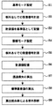
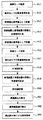
図7は、第1の実施例の樹木診断装置の測定手順を示すフローチャートである。まず、計測モード切替部を基準モードに設定する(S1)。この状態で樹木診断を行う場合と同一の機材配置で樹木診断装置を設置し、各受信アンテナで受信される透過電波の受信信号の強度を計測する(S2)。さらに計測した透過電波の受信信号の強度を基準値として基準受信信号記憶部に記憶する(S3)。 FIG. 7 is a flowchart illustrating a measurement procedure of the tree diagnostic apparatus according to the first embodiment. First, the measurement mode switching unit is set to the reference mode (S1). In this state, the tree diagnosis apparatus is installed with the same equipment arrangement as that for performing tree diagnosis, and the intensity of the received signal of the transmitted radio wave received by each receiving antenna is measured (S2). Further, the measured received signal intensity of the transmitted radio wave is stored in the reference received signal storage unit as a reference value (S3).
次に、計測モード切替部を診断モードに設定する(S4)。この状態で、計測対象の樹木100の葉101を送信装置と受信装置で挟む機材配置とし、各受信アンテナから受信される受信信号の強度を計測する(S5)。この計測した透過電波の受信信号の強度を受信信号記憶部に記憶する(S6)。 Next, the measurement mode switching unit is set to the diagnosis mode (S4). In this state, the equipment arrangement is such that the
次に、各受信アンテナからの計測値と、各アンテナに対応した基準値から葉101による透過損失を算出する(S7)。 Next, the transmission loss by the
次に、各受信アンテナから得られる透過損失から標準偏差値を算出する(S8)。最後に、透過損失の標準偏差値から樹木の脱水率を算出し、樹木の健康状態の診断を行う(S9)。 Next, a standard deviation value is calculated from the transmission loss obtained from each receiving antenna (S8). Finally, the dehydration rate of the tree is calculated from the standard deviation value of the transmission loss, and the health condition of the tree is diagnosed (S9).
以上のように、機能構成図に示す機能を用い、フローチャートに示す測定手順を用いることにより、樹木診断が可能となる。 As described above, tree diagnosis is possible by using the functions shown in the functional configuration diagram and using the measurement procedure shown in the flowchart.
次に、この発明に係わる樹木診断方法及び装置の第2の実施例における手順について図8〜図11を参照して説明する。 Next, a procedure in the second embodiment of the tree diagnosis method and apparatus according to the present invention will be described with reference to FIGS.
図8は第2の実施例の樹木診断装置の概略斜視図である。樹木診断装置は、送信装置1と受信装置3と受信信号ケーブル41と信号処理装置5とから構成される。送信装置1は、送信アンテナ12A、12B、12Cを装備し、支柱15に取付けられる。この支柱15は「第1の移動手段」としての送信装置移動部7の移動溝73に沿って、図示しない駆動部により図中矢印方向に移動可能に取付けられている。受信装置2は、受信アンテナ31A、31B、31Cを装備し、支柱35に取付けられている。この支柱35は「第2の移動手段」としての受信装置移動部8の移動溝83に沿って、図示しない駆動部により図中矢印方向に移動可能に取付けられている。送信アンテナ31Aから放射される放射電波21は、樹木100の葉101に照射されて、葉101を透過した後に、透過電波22として受信アンテナ31Aにより受信される。同様に送信アンテナ31Bから放射される放射電波21は、樹木100の異なる部分の葉101に照射されて、葉101を透過した後に、透過電波22として受信アンテナ31Bにより受信される。さらに送信アンテナ31Cから放射される放射電波21は、樹木100のさらに異なる葉101に照射されて、葉101を透過した後に、透過電波22として受信アンテナ31Cにより受信される。これらの受信された信号は受信信号ケーブル41により信号処理装置5へ伝送される。 FIG. 8 is a schematic perspective view of the tree diagnostic apparatus according to the second embodiment. The tree diagnosis apparatus includes a
また、信号処理装置5と送信装置移動部7との間には、支柱15を移動させる駆動部駆動信号を伝送する駆動信号ケーブル42が設けられている。また、信号処理装置5と受信装置移動部8の間には、支柱35を移動させる駆動部駆動信号を伝送する駆動信号ケーブル43が設けられている。 Further, a
図9は第2の実施例の樹木診断装置の概略平面図である。送信装置1は図示しない支柱に取付けられ、この支柱は送信装置移動部7の移動溝73に移動可能に取付けられる。さらにこの支柱は移動溝73内に設けられた図示しない駆動部により矢印方向へAの位置、Bの位置まで移動可能である。同様に受信装置3は図示しない支柱に取付られ、この支柱は受信装置移動部8の移動溝83に移動可能に取付られる。さらにこの支柱は移動溝83内に設けられた図示しない駆動部により矢印方向へCの位置、Dの位置まで移動可能である。送信装置1の送信アンテナ12Aから放射された放射電波21は樹木の葉101を透過し、葉101を透過した後に、透過電波22として受信アンテナ31Aで受信される。同様に図示しない送信アンテナ12Bからの透過電波は図示しない受信アンテナ31Bで、図示しない送信アンテナ12Cからの透過電波は図示しない受信アンテナ31Cで受信される。次に送信装置1を移動溝73内のAまで移動させ、同様に受信装置3を移動溝83内のCまで移動させる。この状態で送信装置1の送信アンテナ12Aから放射された透過電波は受信アンテナ31Aで受信され、同様に図示しない送信アンテナ12Bからの透過電波は図示しない受信アンテナ31Bで、図示しない送信アンテナ12Cからの透過電波は図示しない受信アンテナ31Cで受信される。さらに送信装置1を移動溝73内のBまで移動させ、同様に受信装置3を移動溝83内のDまで移動させる。この状態で送信装置1の送信アンテナ12Aから放射された透過電波は受信アンテナ31Aで受信され、同様に図示しない送信アンテナ12Bからの透過電波は図示しない受信アンテナ31Bで、図示しない送信アンテナ12Cからの透過電波は図示しない受信アンテナ31Cで受信される。以上の測定により、それぞれ3個の送信アンテナと受信アンテナを3個所で固定し計測することにより、樹木100の葉101の異なった9箇所を透過する透過電波を受信することが可能となる。 FIG. 9 is a schematic plan view of the tree diagnostic apparatus according to the second embodiment. The
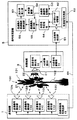
図10は第2の実施例の樹木診断装置の機能構成図である。樹木診断装置は、送信装置1と受信装置3と受信信号ケーブル41と信号処理装置5とから構成される。送信装置1は、送信信号発生部1A、11B、11Cと送信アンテナ12A、12B、12Cとから構成される。受信装置3は、受信アンテナ31A、31B、31Cと、受信信号検出部32A、32B、33Cと、AD変換部33A、33B、33Cと、伝送信号駆動部34とから構成される。送信装置移動部7は、駆動制御部71と駆動部72とから構成される。受信装置移動部8は、駆動制御部81と駆動部82とから構成される。信号処理装置5は、伝送信号検出部51と、計測モード切替部52と、基準受信信号記憶部53と、受信信号記憶部54と、透過損失算出部55と、透過損失標準偏差値算出部56と、脱水率算出部57と、樹木診断部58と、送信/受信移動制御部59と、駆動信号ケーブル42、43とから構成される。 FIG. 10 is a functional configuration diagram of the tree diagnosis apparatus according to the second embodiment. The tree diagnosis apparatus includes a
送信アンテナ31Aから放射される放射電波21は、樹木100の葉101に照射される。葉101を透過した透過電波22は受信アンテナ31Aで受信される。同様に送信アンテナ31Bから放射される放射電波21は、樹木100の異なる部分の葉101に照射される。葉101を透過した透過電波22は受信アンテナ31Bで受信される。さらに送信アンテナ31Cから放射される放射電波21は、樹木100のさらに異なる葉101に照射される。葉101を透過した透過電波22は受信アンテナ31Cで受信される。受信アンテナ31A、31B、31Cで受信された受信信号は、受信信号検出部32A、32B、32Cで検出され、さらにAD変換部33A、33B、33Cによりそれぞれデジタル信号に変換され、3個のデジタル受信信号が得られる。さらに、送信装置1は送信装置移動部7の移動溝73内に設けられた駆動部72により矢印方向へ図9のAの位置、Bの位置まで移動し、受信装置3は受信装置移動部8の移動溝83内に設けられた駆動部82により矢印方向へ図9のCの位置、Dの位置まで移動する。この状態で、さらに受信アンテナ31A、31B、31Cで受信され、受信信号検出部32A、32B、32Cで検出され、AD変換部33A、33B、33Cによりデジタル信号に変換される。その結果、受信デジタル信号は6個となり、前の3個と合わせて合計9個となる。これら9個のデジタル受信信号は伝送信号駆動部34から、受信信号ケーブル41を介して信号処理装置5へ送出される。
受信信号ケーブル41により送出された9個のデジタル受信信号は、信号処理装置5の伝送信号検出部51で受信され、計測モード切替部52へ送出される。計測モード切替部52へ送出された9個のデジタル信号は計測モード切替部52が基準モードの場合基準受信信号記憶部53へ、診断モードの場合受信信号記憶部54へ送出される。透過損失算出部55では、受信信号記憶部54から送出された9個のデジタル受信信号とこれらに対応する基準受信信号記憶部53からの9個のデジタル受信信号を用いて、9個の透過損失が求められる。これらの9個の透過損失データから透過損失標準偏差値算出部56では透過損失の標準偏差値が算出される。さらに、この透過損失の標準偏差値から脱水率算出部57で葉101の脱水率が算出され、この値に基づいて樹木診断部58で樹木100の健康状態の診断が行われる。 Nine digital reception signals transmitted by the
樹木100の樹木診断に必要な樹木100の葉101の透過損失は以下のように算出される。まず、計測モード切替部52を基準モードに切替える。この場合、測定のための機材は樹木診断を行う場合と同じ配置とし、測定対象物の樹木100がない場合の放射電波21を受信アンテナ31A、31B、31Cで受信する。さらに受信信号検出部32A、32B、32Cで検出され、AD変換部33A、33B、33Cの出力として得られる放射電波の強度の計測値を基準信号記憶部53に基準値として記憶する。同様に送信装置1をAの位置、受信装置3をCの位置にして得られる放射電波の強度の計測値、送信装置1をDの位置、受信装置3をCの位置にして得られる放射電波の強度の計測値をそれぞれ基準受信信号記憶部53に基準値として記憶する。次に計測モード切替部52を診断モードに切替える。この場合、測定のための機材は樹木診断を行う場合の配置とし、対象物の葉101を放射電波21で照射し、照射後の透過電波22を受信アンテナ31A、31B、31Cで受信する。さらに受信信号検出部32A、32B、32Cで検出され、AD変換部33A、33B、33Cの出力として得られる放射電波の強度の計測値を受信信号記憶部54に記憶する。同様に送信装置1をAの位置、受信装置3をCの位置にして得られる放射電波の強度の計測値、送信装置1をDの位置、受信装置3をCの位置にして得られる放射電波の強度の計測値をそれぞれ受信信号記憶部54に記憶する。樹木100の葉101の透過損失は放射電波の強度の計測値と透過電波の計測値から、(放射電波の強度の計測値−透過電波の強度の計測値)/(放射電波の強度の計測値)なる式により算出される。 The transmission loss of the
受信装置3を3箇所に設置し、それぞれの場所で受信アンテナ31A、31B、31Cにより受信される透過電波22は、葉101のそれぞれ異なる9個所の部分を通過するため、それぞれの透過損失は異なる。これら9箇所の透過損失のばらつきは、葉の枚数より葉に含まれる水分量に大きく依存する。透過損失のばらつきは、水分量が多く樹木の健康状態が良好な場合は大きくなり、水分量が少なく樹木の健康状態が悪く枯れる寸前の樹木の場合は少なくなる。したがって、透過損失のばらつきの大きさを標準偏差値として定量的に把握することにより、樹木100の葉101の水分量が推定でき、樹木の健康状態の診断が可能となる。 The receiving
図11は、第2の実施例の樹木診断装置の測定手順を示すフローチャートである。まず、計測モード切替部を基準モードに設定する(S11)。この状態で樹木診断を行う場合と同一の機材配置で樹木診断装置を設置し、各受信アンテナで受信される透過電波の受信信号の強度を計測する(S12)。計測した透過電波の受信信号の強度を基準値として基準受信信号記憶部に記憶する(S13)。 FIG. 11 is a flowchart showing a measurement procedure of the tree diagnostic apparatus according to the second embodiment. First, the measurement mode switching unit is set to the reference mode (S11). In this state, a tree diagnosis apparatus is installed with the same equipment arrangement as that for tree diagnosis, and the intensity of the received signal of the transmitted radio wave received by each receiving antenna is measured (S12). The measured received signal intensity of the transmitted radio wave is stored in the reference received signal storage unit as a reference value (S13).
次に、送信装置、受信装置をともに横方向に移動させて各受信アンテナで受信される透過電波の受信信号の強度を計測する。この計測を複数回繰り返す(S14)。計測した透過電波の受信信号の強度を基準値として基準受信信号記憶部に記憶する(S15)。 Next, both the transmitting device and the receiving device are moved laterally, and the intensity of the received signal of the transmitted radio wave received by each receiving antenna is measured. This measurement is repeated a plurality of times (S14). The measured received signal intensity of the transmitted radio wave is stored in the reference received signal storage unit as a reference value (S15).
次に、計測モード切替部を診断モードに設定する(S16)。この状態で、計測対象の樹木100の葉101を送信装置と受信装置で挟む機材配置とし、各受信アンテナから受信される受信信号の強度を計測する(S17)。計測した透過電波の受信信号の強度を受信信号記憶部に記憶する(S18)。 Next, the measurement mode switching unit is set to the diagnosis mode (S16). In this state, the equipment arrangement is such that the
次に、送信装置、受信装置をともに横方向に移動させて各受信アンテナで受信される透過電波の受信信号の強度を計測する。この計測を複数回繰り返す(S19)。計測した透過電波の受信信号の強度を受信信号記憶部に記憶する(S20)。 Next, both the transmitting device and the receiving device are moved laterally, and the intensity of the received signal of the transmitted radio wave received by each receiving antenna is measured. This measurement is repeated a plurality of times (S19). The measured received signal strength of the transmitted radio wave is stored in the received signal storage unit (S20).
次に、各受信アンテナからの計測値と、各アンテナに対応した基準値から葉101による透過損失を算出する(S21)。 Next, the transmission loss by the
次に、各受信アンテナから得られる透過損失から標準偏差値を算出する(S22)。最後に、透過損失の標準偏差値から樹木の脱水率を産出し、樹木の健康状態の診断を行う(S23)。 Next, a standard deviation value is calculated from the transmission loss obtained from each receiving antenna (S22). Finally, the dehydration rate of the tree is produced from the standard deviation value of the transmission loss, and the health condition of the tree is diagnosed (S23).
以上のように、機能構成図に示す機能を用い、フローチャートに示す測定手順を用いることにより、樹木診断が可能となる。 As described above, tree diagnosis is possible by using the functions shown in the functional configuration diagram and using the measurement procedure shown in the flowchart.
以下に、この発明に係わる樹木診断方法及び装置の第3の実施例における手順について図12〜図14を参照して説明する。 The procedure in the third embodiment of the tree diagnosis method and apparatus according to the present invention will be described below with reference to FIGS.
図12は第3の実施例の樹木診断装置の概略斜視図である。樹木診断装置は、送信装置1と受信装置3と受信信号ケーブル41と信号処理装置5とから構成される。送信装置1は、送信アンテナ12A、12B、12C、12Dを装備し、支柱15により地上に固定される。受信装置3は、受信アンテナ31を装備し、支柱35により地上に固定される。送信アンテナ12A、12B、12C、12Dから放射される放射電波21は、樹木100の葉101に照射される。樹木100は葉101と幹102とから構成されるが、放射電波21は主に葉101に照射される。葉101のそれぞれ異なる部分を透過した透過電波22は受信アンテナ31により受信される。受信された信号は受信信号ケーブル41により信号処理装置5へ伝送される。また、送信装置1から信号処理装置5へ送信同期信号が同期信号ケーブル44を介して送出される。 FIG. 12 is a schematic perspective view of the tree diagnosis apparatus of the third embodiment. The tree diagnosis apparatus includes a
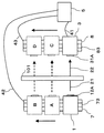
図13は第1の実施例の樹木診断装置の機能構成図である。樹木診断装置は、送信装置1と受信装置3と受信信号ケーブル41と信号処理装置5とから構成される。送信装置1は、送信信号発生部11A、11B、11C、11Dと送信アンテナ12A、12B、12C、12Dと、送信同期信号発生部13とから構成される。受信装置3は、受信アンテナ31と、受信信号検出部32と、AD変換部33と、伝送信号駆動部34とから構成される。信号処理装置5は、伝送信号検出部51と、計測モード切替部52と、基準受信信号記憶部53と、受信信号記憶部54と、透過損失算出部55と、透過損失標準偏差値算出部56と、脱水率算出部57と、樹木診断部58と、受信信号同期部60とから構成される。受信信号同期部60は送信装置1の送信同期信号発生部13から同期信号ケーブル44を介して送信同期信号を受け取る。 FIG. 13 is a functional configuration diagram of the tree diagnosis apparatus according to the first embodiment. The tree diagnosis apparatus includes a
送信アンテナ12A、12B、12C、12Dから放射される放射電波21は樹木100の葉101に照射される。この場合、送信同期信号発生部13からの送信同期信号により送信アンテナは12A、12B、12C、12Dの順に時系列で切替わり電波を放射する。葉101に照射された放射電波21は、葉101を透過後、透過電波22として受信アンテナ31で受信される。受信アンテナ31により受信された受信信号は受信信号検出部32により検出され、さらにAD変換部33によりデジタル信号に変換される。デジタル信号に変換されたデジタル受信信号は伝送信号駆動部34により、受信信号ケーブル41を介して信号処理装置5へ送出される。
受信信号ケーブル41により送出されたデジタル受信信号は、信号処理装置5の伝送信号検出部51で受信され計測モード切替部52へ送出される。計測モード切替部52へ送出されたデジタル受信信号は、計測モード切替部52が基準モードの場合基準受信信号記憶部53へ、診断モードの場合受信信号記憶部54へ送出される。この際、受信信号同期部60からの送信同期信号により基準受信信号記憶部53、受信信号記憶部54は、送信アンテナ11A、11B、11C、11Dからの放射電波に対応したデジタル受信信号を分離、記憶する。このため、基準受信信号記憶部53、受信信号記憶部54ではそれぞれ4個のデジタル受信信号が記憶される。透過損失算出部55では、受信信号記憶部54から送出された4個のデジタル受信信号とこれらに対応する基準受信信号記憶部53の4個のデジタル受信信号を用いて、4個の透過損失が求められる。この4個の透過損失データから透過損失標準偏差値算出部56で透過損失の標準偏差値が算出される。さらに、この透過損失の標準偏差値から脱水率算出部57で樹木100の葉101の脱水率が算出され、この値に基づいて樹木診断部58で樹木100の葉101の健康状態の診断が行われる。 The digital reception signal transmitted by the
送信アンテナ12A、12B、12C、12Dから放射された放射電波は、おもに樹木100により反射され、吸収される。そのため、受信アンテナ31に到達するそれぞれの透過電波22の強度は、放射電波21の強度に対して減少する。この減少量が透過損失である。この透過損失は主に樹木の水分による吸収損失で決まり、反射損失には殆んど依存しない。そのため、水分の吸収に起因する透過損失の測定から樹木100の健康状態が診断可能となる。すなわち、樹木の健康が順調な場合、樹木100の水分量はある一定量保持されるが、樹木の健康が何らかの理由で阻害され枯れたりすると減少する。従って、水分の抜け具合からその樹木の健康状態が診断可能となる。この水分量の変化は樹木100の幹102より葉101が著しい。そのため、樹木100の葉101の水分量を検知することによりさらに精度よく樹木の健康状態の診断ができる。 Radiated radio waves radiated from the transmitting
樹木100の樹木診断に必要な樹木100の葉101の透過損失は以下のように算出される。まず、計測モード切替部52を基準モードに切替える。この場合、測定のための機材は樹木診断を行う場合と同じ配置とし、測定対象物の樹木100がない場合のアンテナ12A、12B、12C、12Dからの放射電波21を受信アンテナ31で受信する。さらに受信信号検出部32で検出され、AD変換部33の出力として得られ、かつ受信信号同期部60で分離された放射電波の強度の計測値を基準信号記憶部53に基準値として記憶する。次に計測モード切替部52を診断モードに切替える。この場合、測定のための機材は樹木診断を行う場合の配置とし、対象物の葉101を放射電波21で照射し、照射後の透過電波22を受信アンテナ31で検出する。さらに、受信信号検出部32で検出され、AD変換部33の出力として得られ、かつ受信信号同期部60で分離された、透過電波の強度の計測値を受信信号記憶部54に記憶する。樹木100の葉101の透過損失は放射電波の強度の計測値と透過電波の強度の計測値から、(放射電波の強度の計測値−透過電波の強度の計測値)/(放射電波の強度の計測値)なる式により算出される。 The transmission loss of the
送信アンテナ12A、12B、12C、12Dで放射され受信アンテナ31で受信される透過電波22は葉101のそれぞれ異なる部分を通過するため、それぞれの透過損失は異なる。これら4箇所を透過する透過電波の透過損失のばらつきは、葉の枚数より葉に含まれる水分量に大きく依存する。透過損失のばらつきは、水分量が多く樹木の健康状態が良好な場合は大きく、水分量が少なく樹木の健康状態が悪く枯れる寸前の樹木の場合は少ない。したがって、透過損失のばらつきの大きさを標準偏差値として定量的に把握することにより、樹木100の葉101の水分量が定量的に推定でき、樹木の健康状態の診断が可能となる。 Since the transmitted
図14は、第3の実施例の樹木診断装置の測定手順を示すフローチャートである。まず、計測モード切替部を基準モードに設定する(S31)。この状態で樹木診断を行う場合と同一の機材配置で樹木診断装置を設置し、各送信アンテナからの放射電波が樹木を透過した後の、透過電波の受信信号の強度を計測する(S32)。 FIG. 14 is a flowchart showing a measurement procedure of the tree diagnostic apparatus according to the third embodiment. First, the measurement mode switching unit is set to the reference mode (S31). In this state, the tree diagnosis apparatus is installed with the same equipment arrangement as that used for tree diagnosis, and the intensity of the received signal of the transmitted radio wave after the radio wave transmitted from each transmitting antenna passes through the tree is measured (S32).
次に、送信同期信号発生部からの同期信号により、各送信アンテナからの放射電波に対応した受信信号の分離を行う(S33)。分離した透過電波の受信信号の強度を基準値として基準受信信号記憶部に記憶する(S34)。 Next, the received signal corresponding to the radiated radio wave from each transmitting antenna is separated based on the synchronizing signal from the transmitting synchronizing signal generator (S33). The intensity of the received signal of the separated transmitted radio wave is stored in the reference received signal storage unit as a reference value (S34).
次に、計測モード切替部を診断モードに設定する(S−35)。この状態で、計測対象の樹木100の葉101を送信装置と受信装置で挟む機材配置とし、各送信アンテナからの放射電波が樹木を透過した後の、透過電波の受信信号の強度を計測する(S36)。 Next, the measurement mode switching unit is set to the diagnosis mode (S-35). In this state, the
次に、送信同期信号発生部からの同期信号により、各送信アンテナからの放射電波に対応した受信信号の分離を行う(S37)。分離した透過電波の受信信号の強度を受信信号記憶部に記憶する(S38)。 Next, the received signal corresponding to the radiated radio wave from each transmitting antenna is separated based on the synchronizing signal from the transmitting synchronizing signal generator (S37). The intensity of the received signal of the separated transmitted radio wave is stored in the received signal storage unit (S38).
次に、受信信号記憶部に記憶された計測値と、基準信号記憶部に記憶された基準値から葉101による透過損失を算出する(S39)。 Next, the transmission loss due to the
次に、各受信アンテナから得られる透過損失から標準偏差値を算出する(S40)。最後に、透過損失の標準偏差値から樹木の脱水率を算出し、樹木の健康状態の診断を行う(S41)。 Next, a standard deviation value is calculated from the transmission loss obtained from each receiving antenna (S40). Finally, the dehydration rate of the tree is calculated from the standard deviation value of the transmission loss, and the health condition of the tree is diagnosed (S41).
以上のように、機能構成図に示す機能を用い、フローチャートに示す測定手順を用いることにより、樹木診断が可能となる。 As described above, tree diagnosis is possible by using the functions shown in the functional configuration diagram and using the measurement procedure shown in the flowchart.
本発明は、上述した実施例の手順に限定されることなく、この発明の要旨を逸脱しない範囲で、種々の変形が可能であることは言うまでない。 It goes without saying that the present invention is not limited to the procedure of the above-described embodiment, and various modifications can be made without departing from the gist of the present invention.
例えば、本実施形態では送信装置、受信装置とも固定とし、送信アンテナが1個の場合で受信アンテナが2×2の場合、送信アンテナが2×2の場合で受信アンテナが1個の場合について示したが、送信アンテナが1個で受信アンテナが1個の場合を除く、送信アンテナがM×N、受信アンテナがL×Kの場合についても適用可能なことは言うまでもない。 For example, in the present embodiment, both the transmission device and the reception device are fixed, the case where there is one transmission antenna, the reception antenna is 2 × 2, the case where the transmission antenna is 2 × 2, and the case where there is one reception antenna is shown. However, it goes without saying that the present invention can also be applied to the case where the transmission antenna is M × N and the reception antenna is L × K, except for the case where there is one transmission antenna and one reception antenna.
また、本実施形態では送信装置、受信装置とも横方向に移動可能で、送信アンテナが3×1で受信アンテナが3×1の場合についての例を示したが、送信装置、受信装置とも横方向に移動可能であり、かつ送信アンテナがM×N、受信アンテナがL×Kの場合についても適用可能なことは言うまでもない。 In this embodiment, both the transmitting device and the receiving device are movable in the horizontal direction, and the example in which the transmitting antenna is 3 × 1 and the receiving antenna is 3 × 1 is shown. Needless to say, the present invention can also be applied to a case where the transmission antenna is M × N and the reception antenna is L × K.
1:送信装置
11:送信信号発生部
11A:送信信号発生部
11B:送信信号発生部
11C:送信信号発生部
11D:送信信号発生器
12:送信アンテナ
12A:送信アンテナ
12B:送信アンテナ
12C:送信アンテナ
12D:送信アンテナ
13:送信同期信号発生部
15:支柱
21:放射電波信号
22:透過電波信号
3:受信装置
31:受信信号アンテナ
31A:受信アンテナ
31B:受信アンテナ
31C:受信アンテナ
31D:受信アンテナ
32:受信信号検出部
32A:受信信号検出部
32B:受信信号検出部
32C:受信信号検出部
32D:受信信号検出部
33:AD変換部
33A:AD変換部
33B:AD変換部
33C:AD変換部
33D:AD変換部
34:伝送信号駆動部
35:支柱
41:受信信号ケーブル
42:駆動信号ケーブル
43:駆動信号ケーブル
44:同期信号ケーブル
5:信号処理部
51:伝送信号検出部
52:計測モード切替部
53:基準受信信号記憶部
54:受信信号記憶部
55:透過損失算出部
56:透過損失標準偏差値算出部
57:脱水率算出部
58:樹木診断部
59:送信部/受信部移動制御部
60:受信信号同期部
7:送信装置移動部
71:駆動制御部
72:駆動部
73:移動溝
8:受信装置移動部
81:駆動制御部
82:駆動部
83:移動溝
100:樹木
101:葉
102:幹1: Transmission device 11: Transmission signal generator 11A: Transmission signal generator 11B: Transmission signal generator 11C: Transmission signal generator 11D: Transmission signal generator 12: Transmission antenna 12A: Transmission antenna 12B: Transmission antenna 12C: Transmission antenna 12D: Transmission antenna 13: Transmission synchronization signal generator 15: Support column 21: Radiated radio wave signal 22: Transmitted radio wave signal 3: Reception device 31: Reception signal antenna 31A: Reception antenna 31B: Reception antenna 31C: Reception antenna 31D: Reception antenna 32 : Received signal detector 32A: received signal detector 32B: received signal detector 32C: received signal detector 32D: received signal detector 33: AD converter 33A: AD converter 33B: AD converter 33C: AD converter 33D : AD converter 34: Transmission signal driver 35: Support column 41: Reception signal cable 42: Drive signal box Bull 43: Drive signal cable 44: Synchronization signal cable 5: Signal processing unit 51: Transmission signal detection unit 52: Measurement mode switching unit 53: Reference reception signal storage unit 54: Reception signal storage unit 55: Transmission loss calculation unit 56: Transmission Loss standard deviation value calculation unit 57: dehydration rate calculation unit 58: tree diagnosis unit 59: transmission unit / reception unit movement control unit 60: reception signal synchronization unit 7: transmission device movement unit 71: drive control unit 72: drive unit 73: Moving groove 8: Receiver moving part 81: Drive control part 82: Driving part 83: Moving groove 100: Tree 101: Leaf 102: Trunk
Claims (13)
送信装置により放射した放射電波の強度を受信装置により計測する第1の計測工程と、
前記送信装置により放射した前記放射電波が前記樹木を透過した透過電波の強度を前記受信装置により計測する第2の計測工程と、
信号処理装置により前記第1の計測工程で計測された前記放射電波の強度の計測値と、前記第2の計測工程で計測された前記透過電波の強度の計測値とから強度比を算出する信号処理工程とにより樹木の健康状態を診断することを特徴とする樹木診断方法。In a tree diagnostic method that diagnoses the health of trees by radiating radio waves to the trees,
A first measurement step of measuring the intensity of the radiated radio wave radiated by the transmission device by the reception device;
A second measuring step of measuring, by the receiving device, the intensity of the transmitted radio wave transmitted through the tree by the radiated radio wave radiated by the transmitting device;
A signal for calculating an intensity ratio from the measured value of the intensity of the radiated radio wave measured in the first measuring step by the signal processing device and the measured value of the intensity of the transmitted radio wave measured in the second measuring step. A tree diagnostic method characterized by diagnosing the health state of a tree by a processing step.
前記樹木に放射電波を放射する送信装置と、
前記放射電波が樹木を透過した後の透過電波を受信する受信装置と、
前記放射電波と前記透過電波の強度比から樹木の健康状態を診断する信号処理装置とを具備することを特徴とする樹木診断装置。In a tree diagnostic device that diagnoses the health condition of trees by irradiating trees with radio waves,
A transmitter for radiating radio waves to the tree;
A receiver for receiving the transmitted radio wave after the radiated radio wave has passed through the tree;
A tree diagnostic apparatus comprising: a signal processing apparatus that diagnoses a health state of a tree from an intensity ratio between the radiated radio wave and the transmitted radio wave.
Priority Applications (1)
| Application Number | Priority Date | Filing Date | Title |
|---|---|---|---|
| JP2004130462A JP2005292099A (en) | 2004-03-31 | 2004-03-31 | Tree diagnosis method and apparatus |
Applications Claiming Priority (1)
| Application Number | Priority Date | Filing Date | Title |
|---|---|---|---|
| JP2004130462A JP2005292099A (en) | 2004-03-31 | 2004-03-31 | Tree diagnosis method and apparatus |
Publications (1)
| Publication Number | Publication Date |
|---|---|
| JP2005292099A true JP2005292099A (en) | 2005-10-20 |
Family
ID=35325172
Family Applications (1)
| Application Number | Title | Priority Date | Filing Date |
|---|---|---|---|
| JP2004130462A Pending JP2005292099A (en) | 2004-03-31 | 2004-03-31 | Tree diagnosis method and apparatus |
Country Status (1)
| Country | Link |
|---|---|
| JP (1) | JP2005292099A (en) |
Cited By (3)
| Publication number | Priority date | Publication date | Assignee | Title |
|---|---|---|---|---|
| JP2007195745A (en) * | 2006-01-26 | 2007-08-09 | Toto Ltd | Device for detecting drying state of wet object |
| JP2019128224A (en) * | 2018-01-24 | 2019-08-01 | 応用地質株式会社 | Device and method for diagnosing trees |
| US10605746B2 (en) | 2017-12-18 | 2020-03-31 | United Arab Emirates University | Plant water sensor |
-
2004
- 2004-03-31 JP JP2004130462A patent/JP2005292099A/en active Pending
Cited By (4)
| Publication number | Priority date | Publication date | Assignee | Title |
|---|---|---|---|---|
| JP2007195745A (en) * | 2006-01-26 | 2007-08-09 | Toto Ltd | Device for detecting drying state of wet object |
| US10605746B2 (en) | 2017-12-18 | 2020-03-31 | United Arab Emirates University | Plant water sensor |
| JP2019128224A (en) * | 2018-01-24 | 2019-08-01 | 応用地質株式会社 | Device and method for diagnosing trees |
| JP7000174B2 (en) | 2018-01-24 | 2022-01-19 | 応用地質株式会社 | Tree diagnostic device and tree diagnostic method |
Similar Documents
| Publication | Publication Date | Title |
|---|---|---|
| EP2638797B1 (en) | Plant health diagnostic method and plant health diagnostic device | |
| CN108449988B (en) | Backscatter Imaging for Precision Agriculture | |
| Cseresnyés et al. | Application of electrical capacitance method for prediction of plant root mass and activity in field-grown crops | |
| US5957304A (en) | Crop harvester | |
| Tremblay et al. | Sensing of crop nitrogen status: Opportunities, tools, limitations, and supporting information requirements | |
| Ciganda et al. | How deep does a remote sensor sense? Expression of chlorophyll content in a maize canopy | |
| Inman et al. | On‐the‐go active remote sensing for efficient crop nitrogen management | |
| Mouazen et al. | Optimum three-point linkage set up for improving the quality of soil spectra and the accuracy of soil phosphorus measured using an on-line visible and near infrared sensor | |
| JPH1153674A (en) | Information management system for farm product | |
| CN109187417B (en) | Unmanned aerial vehicle-mounted terahertz wave and hyperspectral remote sensing crop monitoring system | |
| CN104199027A (en) | Method for realizing large-area near real-time monitoring on phenological period of rice based on compactly polarimetric radar | |
| Enciso et al. | A ground based platform for high throughput phenotyping | |
| CN118830825B (en) | Multifunctional array type biological signal acquisition sensor module and control method thereof | |
| Pornaro et al. | Pasture botanical composition and forage quality at farm scale: A case study | |
| JP2005292099A (en) | Tree diagnosis method and apparatus | |
| Biewer et al. | Prediction of yield and the contribution of legumes in legume-grass mixtures using field spectrometry | |
| JP2017042136A (en) | Plant cultivation support device, plant cultivation support method, program, storage medium | |
| RU2384860C2 (en) | Method of detecting people and moving objects behind barrier and device for realising said method | |
| Fan et al. | Evaluating drought stress response of poplar seedlings using a proximal sensing platform via multi-parameter phenotyping and two-stage machine learning | |
| Chukwu et al. | Crown-stump diameter model for Parkia biglobosa Benth. species in Makurdi, Benue State, Nigeria | |
| CN108184071B (en) | Fruit tree planting field monitoring platform | |
| KR101328487B1 (en) | Prediction Method and Device of Rough Rice Harvesting Time | |
| Okoma et al. | Estimation of stem and leaf dry biomass using a non-destructive method applied to African Coffea species | |
| Kaur et al. | Spectral reflectance characteristics to distinguish Malva neglecta in wheat (Triticum aestivum) | |
| Tagarakis et al. | In-field experiments for performance evaluation of a new low-cost active multispectral crop sensor |
Legal Events
| Date | Code | Title | Description |
|---|---|---|---|
| A621 | Written request for application examination |
Effective date: 20070402 Free format text: JAPANESE INTERMEDIATE CODE: A621 |
|
| A977 | Report on retrieval |
Free format text: JAPANESE INTERMEDIATE CODE: A971007 Effective date: 20090105 |
|
| A131 | Notification of reasons for refusal |
Effective date: 20090414 Free format text: JAPANESE INTERMEDIATE CODE: A131 |
|
| A02 | Decision of refusal |
Effective date: 20090811 Free format text: JAPANESE INTERMEDIATE CODE: A02 |