JP2005292086A - Tape measure - Google Patents
Tape measure Download PDFInfo
- Publication number
- JP2005292086A JP2005292086A JP2004111282A JP2004111282A JP2005292086A JP 2005292086 A JP2005292086 A JP 2005292086A JP 2004111282 A JP2004111282 A JP 2004111282A JP 2004111282 A JP2004111282 A JP 2004111282A JP 2005292086 A JP2005292086 A JP 2005292086A
- Authority
- JP
- Japan
- Prior art keywords
- tape
- measure
- measuring tape
- convex
- scale
- Prior art date
- Legal status (The legal status is an assumption and is not a legal conclusion. Google has not performed a legal analysis and makes no representation as to the accuracy of the status listed.)
- Pending
Links
Images
Landscapes
- Tape Measures (AREA)
Abstract
Description
本発明は、巻尺に関する。 The present invention relates to a tape measure.
従来より、コンベックスと呼ばれている小型の巻尺は、巻回された鋼製の検尺テープを筐体内に備え、この検尺テープは、その先端を計測対象物に引っ掛けるための引掛具を備えている。この引掛具は、検尺テープの表面に対して垂直に折り曲げられた爪部を備え、この爪部が、検尺テープの長さ方向の先端に位置するよう検尺テープに取り付けられている。 また、検尺テープの表面には、爪部からの長さを示す目盛が記載されている。 Conventionally, a small tape measure called a convex has a steel measuring tape wound in a housing, and this measuring tape has a hook for hooking the tip of the measuring tape on a measurement object. ing. The hook includes a claw portion that is bent perpendicularly to the surface of the measuring tape, and the claw portion is attached to the measuring tape so that the claw portion is positioned at the front end in the length direction of the measuring tape. Moreover, the scale which shows the length from a nail | claw part is described on the surface of the measuring tape.
このコンベックスを用いて板の長さ等を計るときは、長さを計りたい計測対象物の一端に爪部を引っ掛けて検尺テープを収納している筐体をその他端まで引けばよい。このようにすると筐体内に巻回された検尺テープが筐体から順次出てきて長さを計りたいものの一端から他端まで伸ばされるので、他端に位置する検尺テープの目盛を読めば、爪部を引っ掛けた位置から目盛を読んだ位置までの長さを読むことで、その物の一端から他端までの長さを計ることができる。 When measuring the length or the like of the plate using this convex, it is only necessary to hook the claw portion to one end of the measurement object whose length is to be measured, and pull the casing containing the measuring tape to the other end. In this way, the measuring tape wound in the casing comes out from the casing sequentially and is stretched from one end to the other end of the object whose length is to be measured, so if you read the scale of the measuring tape located at the other end By reading the length from the position where the nail is hooked to the position where the scale is read, the length from one end of the object to the other can be measured.
尚、上記背景技術に記載したコンベックスは、一般市場に広く出回っているものなので、特に先行技術に関する調査は行っていない。 In addition, since the convex described in the above-mentioned background art is widely available in the general market, no investigation on the prior art has been conducted.
ところで、上述したコンベックスで床の長さや部屋の四隅の長さを計ろうとした場合、床面等の計測対象物の表面に対して垂直に爪部を引っ掛けることができないことがある。そのような場合、柱やドア枠などに爪部を引っ掛けてその長さを計測するようなことがあった。 By the way, when it is going to measure the length of a floor and the length of the four corners of a room with the convex mentioned above, it may be impossible to hook a nail | claw part perpendicular | vertical with respect to the surface of measurement objects, such as a floor surface. In such a case, there is a case where the length is measured by hooking a claw portion on a pillar or a door frame.
しかし、このようにすると目盛が表示された検尺テープの表面が上方、すなわち測定者側を向かないので、目盛を読み難いという問題があった。
そこで本発明では、上述した問題点を解決し、計測対象物の表面に対し垂直に爪部を引っ掛けることができない場合でも、目盛が表示された検尺テープの表面を計測者側に向けた状態で検尺テープの先端を固定することができる巻尺を提供することを目的とする。
However, in this case, there is a problem that it is difficult to read the scale because the surface of the measuring tape on which the scale is displayed does not face upward, that is, the measurer side.
Therefore, in the present invention, the above-described problem is solved, and even when the claw portion cannot be hooked perpendicularly to the surface of the measurement object, the surface of the measuring tape on which the scale is displayed faces the measurer side. It aims at providing the tape measure which can fix the front-end | tip of a measuring tape.
上述した問題点を解決するためになされた記載の発明は、 検尺テープの表面に対して垂直に折り曲げられた爪部が、検尺テープの長さ方向の先端に位置するように検尺テープに取り付けられた引掛具を備える巻尺において、爪部は、検尺テープの幅より幅広に形成されていることを特徴とする。この巻尺は、テープの幅より広い部分を柱やドア枠などに引っ掛けることで、目盛が表示された検尺テープの表面を計測者側に向けた状態で検尺テープの先端を固定することができる。従って、この巻尺を用いれば、計測対象物の表面に対し垂直に爪部を引っ掛けることができない場合でも、幅広の部分を引っ掛けることができれば、目盛が表示された表面を計測者側に向けて計測することができる。 The invention described in order to solve the above-described problem is that the claw portion bent perpendicularly to the surface of the measuring tape is positioned at the front end in the length direction of the measuring tape. In the tape measure provided with the hook attached to the tape, the claw portion is formed wider than the width of the measuring tape. With this tape measure, the tip of the measuring tape can be fixed with the surface of the measuring tape on which the scale is displayed facing the measurer by hooking a part wider than the width of the tape onto a pillar or door frame. it can. Therefore, using this tape measure, even if the claw part cannot be hooked perpendicularly to the surface of the measurement object, if the wide part can be hooked, the surface on which the scale is displayed is directed toward the measurer. can do.
爪部は、対象物に着接可能に形成されていることが好ましい。このようにすれば、爪部を対象物に当てれば爪部が固定されるので、あとは検尺テープを伸ばせば対象物から所定位置までの長さの計測が可能となる。しかも、この巻尺では爪部を着接するだけで計測ができるので、目盛が記された表面を任意の方向に向けることができる。従って、この巻尺を用いると、計測対象物の表面に垂直に爪部を引っ掛けることができない場合でも、目盛が記された表面を計測者側に向けて計測することができる。尚、対象物としては、鉄等の磁石と磁力によって着接可能なものが主に想定されるので、爪部は、磁石部を備えていることが好ましい。また、対象物に着接可能な構成としては、爪部を対象物に繰り返し張ったり剥がしたりすることができる接着部材を積層してもよい。 It is preferable that the nail | claw part is formed so that attachment to the target object is possible. In this way, the nail portion is fixed when the nail portion is applied to the object, and then the length from the object to the predetermined position can be measured by extending the measuring tape. Moreover, since this tape measure can be measured simply by attaching the claw part, the surface on which the scale is marked can be directed in an arbitrary direction. Therefore, when this tape measure is used, even when the claw portion cannot be hooked perpendicularly to the surface of the measurement object, the surface on which the scale is marked can be measured toward the measurer side. In addition, since what can be contact | attached by magnets, such as iron, with a magnetic force is mainly assumed as a target object, it is preferable that the nail | claw part is equipped with the magnet part. Moreover, as a structure which can be contact | attached to a target object, you may laminate | stack the adhesive member which can stretch | stretch or peel a nail | claw part on a target object repeatedly.
以下、本発明を実施するための最良の形態について図面を用いて説明する。
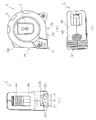
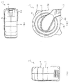
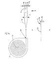
図1及び図2は、本実施形態のコンベックスの六面図で、図1(a)は正面図、図1(b)は右側面図、図1(c)は底面図、図2(a)は背面図、図2(b)は平面図、図2(c)は左側面図である。図3は、コンベックスの概略構成図で、(a)はコンベックスを左側面図、(b)は(a)の平面図で表された検尺テープの先端を矢印αの方向(検尺テープの表面に平行な方向)から見た図である。
The best mode for carrying out the present invention will be described below with reference to the drawings.
1 and 2 are six views of the convex of this embodiment, FIG. 1 (a) is a front view, FIG. 1 (b) is a right side view, FIG. 1 (c) is a bottom view, and FIG. ) Is a rear view, FIG. 2B is a plan view, and FIG. 2C is a left side view. FIG. 3 is a schematic configuration diagram of the convex. (A) is a left side view of the convex, and (b) is a plan view of the measuring tape represented by the plan view of (a). It is the figure seen from the direction parallel to the surface.
本実施形態のコンベックス1(本発明の巻尺に相当する)は、図1,2に示すように、鋼製の検尺テープ10を巻回した状態(図3参照)で収納可能な筐体2を備えている。この筐体2の厚み方向に沿った側面は、正面側側面2aと底面側側面2bとが垂直に交わり、その他の部分2cは、その断面が巻回された検尺テープ10と同軸な円状に形成されている(図3参照)。このうち正面側側面2aには、底面側側面2bと交わる部分の近傍に、筐体2内に収納されていた検尺テープ10を出し入れ可能な挿抜孔20が形成されている(図3参照)。
The
検尺テープ10は、図3に示すように、筐体2内に回転可能に設けられた回転軸12に巻きつけられて筐体2内に収納されている。また、検尺テープは引掛具3を備えており、この引掛具3は、検尺テープ10の表面に対して垂直に折り曲げられた爪部3aが、検尺テープ10の長さ方向の先端に位置するように検尺テープ10に取り付けられている。そして、その爪部3aは、その幅aが、検尺テープ10の幅bより幅広に形成されている。さらにこの爪部3aは、対象物に対向する面に磁石3bが取り付けられている。また、この検尺テープ10の目盛が書かれた表面に、ナイロンでコーティングされている。
As shown in FIG. 3, the
本実施形態のコンベックス1はゴム製のカバー4を備えており、筐体2はこのカバー4で覆われている。また、本実施形態のコンベックス1は、ストッパーを4a、4bを備えており、一つ4aは正面側側面2a、一つ4bは底面側側面2bに備えられている。
The
このように構成されたコンベックス1の筐体2内から検尺テープ10を外部に引き出すには、引掛具3を引けばよい。引掛具3を引くと、筐体2内に収納された検尺テープ10が回転し、外周側のものから順に挿抜孔に向かって接線方向に外部に導かれ、挿抜孔20から引き出される。
To pull out the
また、このコンベックス1は、検尺テープ10が筐体2内に収納されて巻回されるよう付勢する図示しない付勢手段を備えているので、引掛具3を引掛けたり検尺テープ10を持つなどして検尺テープ10が筐体2から引き出された状態を維持しないと、検尺テープ10は自動的に筐体2内に収納されるように構成されている。ただし、このように構成されているため、引掛具3の引掛けが解けてしまうと、このコンベックス1は検尺テープ10を巻き込んでしまう。そのため、本実施形態のコンベックス1は、二つのストッパー4a、4bを備え、手元で検尺テープ10が筐体2内に収納されないようにするとめておくことができる。尚、これらストッパー4a、4bについては周知なので説明は詳細な説明は省略する。
Further, the
以上説明したコンベックス1を用いると以下のような効果がある。
このコンベックス1は、検尺テープ10の幅bより広い部分を柱やドア枠などに引っ掛けることで、目盛が記された表面を上に向けたまま検尺テープ10を伸ばすことができる。従って、このコンベックス1を用いれば、計測対象物の表面に対し垂直に爪部3aを引っ掛けることができない場合でも、目盛が表示された検尺テープ10の表面を計測者側に向けた状態で検尺テープ10の先端を固定することができる。
Use of the
The
また、本実施形態のコンベックス1は、爪部3aを対象物に当てれば磁石3bによって爪部3aが対象物に固定されるので、あとは検尺テープ10を伸ばせば対象物から所定位置までの長さの計測が可能となる。しかも、このコンベックス1では爪部3aを着接するだけで計測ができるので、目盛が記された表面を任意の方向に向けることができる。従って、このコンベックス1を用いると、爪部3aで引っ掛ける場所がなくても、目盛が記された表面を計測者側に向けて計測することができる。
Further, in the
本実施形態のコンベックス1は、ゴム製のカバー4を備えているので、落下しても筐体2が割れ難くすることができる。
さらに本実施形態のコンベックス1は、テープにナイロンコートが施されているので、目盛等の文字の擦り切れを防止する効果が、検尺テープの反射防止効果がある。
Since the
Furthermore, since the
尚、以上本発明の一実施形態ついて説明したが、本発明はこの実施形態に何等限定されるものではなく、本発明の要旨を逸脱しない範囲において、種々なる態様で実施し得ることは勿論である。 Although one embodiment of the present invention has been described above, the present invention is not limited to this embodiment, and can of course be implemented in various modes without departing from the gist of the present invention. is there.
例えば、本実施形態では、爪部3aに磁石を取り付けたが、繰り返し対象物に着接可能な接着剤を積層してもよい。
For example, in the present embodiment, a magnet is attached to the
1…コンベックス、2…筐体、3…引掛具、3a…爪部、3b…磁石、4…カバー、4a…ストッパー、10…検尺テープ、12…回転軸、20…挿抜孔
DESCRIPTION OF
Claims (3)
前記爪部は、前記検尺テープの幅より幅広に形成されていることを特徴とする巻尺。 In a tape measure comprising a hook attached to the measuring tape so that the claw part bent perpendicularly to the surface of the measuring tape is located at the tip in the length direction of the measuring tape,
The tape measure, wherein the claw portion is formed wider than the width of the measuring tape.
前記爪部は、対象物に着接可能に形成されていることを特徴とする巻尺。 The tape measure of claim 1,
A tape measure characterized in that the claw portion is formed so as to be attached to an object.
前記爪部は、磁石部を備えていることを特徴とする巻尺。
The tape measure of claim 2,
The claw part is provided with a magnet part.
Priority Applications (1)
| Application Number | Priority Date | Filing Date | Title |
|---|---|---|---|
| JP2004111282A JP2005292086A (en) | 2004-04-05 | 2004-04-05 | Tape measure |
Applications Claiming Priority (1)
| Application Number | Priority Date | Filing Date | Title |
|---|---|---|---|
| JP2004111282A JP2005292086A (en) | 2004-04-05 | 2004-04-05 | Tape measure |
Publications (1)
| Publication Number | Publication Date |
|---|---|
| JP2005292086A true JP2005292086A (en) | 2005-10-20 |
Family
ID=35325160
Family Applications (1)
| Application Number | Title | Priority Date | Filing Date |
|---|---|---|---|
| JP2004111282A Pending JP2005292086A (en) | 2004-04-05 | 2004-04-05 | Tape measure |
Country Status (1)
| Country | Link |
|---|---|
| JP (1) | JP2005292086A (en) |
Cited By (1)
| Publication number | Priority date | Publication date | Assignee | Title |
|---|---|---|---|---|
| US7124515B2 (en) * | 1999-11-10 | 2006-10-24 | Michael Juenemann | Magnetic tip for tape measure and method of use |
Citations (5)
| Publication number | Priority date | Publication date | Assignee | Title |
|---|---|---|---|---|
| JPS593301U (en) * | 1982-06-28 | 1984-01-10 | 林 和俊 | vertical tape measure |
| JPH0461002U (en) * | 1990-10-01 | 1992-05-26 | ||
| JPH0635901U (en) * | 1992-10-12 | 1994-05-13 | 真司 廣田 | scale |
| JPH1030901A (en) * | 1996-07-12 | 1998-02-03 | Daigo Takamura | Tape measure |
| JP2003041764A (en) * | 2001-08-01 | 2003-02-13 | Masumi Fujii | Positioning tape for architectural external facing |
-
2004
- 2004-04-05 JP JP2004111282A patent/JP2005292086A/en active Pending
Patent Citations (5)
| Publication number | Priority date | Publication date | Assignee | Title |
|---|---|---|---|---|
| JPS593301U (en) * | 1982-06-28 | 1984-01-10 | 林 和俊 | vertical tape measure |
| JPH0461002U (en) * | 1990-10-01 | 1992-05-26 | ||
| JPH0635901U (en) * | 1992-10-12 | 1994-05-13 | 真司 廣田 | scale |
| JPH1030901A (en) * | 1996-07-12 | 1998-02-03 | Daigo Takamura | Tape measure |
| JP2003041764A (en) * | 2001-08-01 | 2003-02-13 | Masumi Fujii | Positioning tape for architectural external facing |
Cited By (1)
| Publication number | Priority date | Publication date | Assignee | Title |
|---|---|---|---|---|
| US7124515B2 (en) * | 1999-11-10 | 2006-10-24 | Michael Juenemann | Magnetic tip for tape measure and method of use |
Similar Documents
| Publication | Publication Date | Title |
|---|---|---|
| US7475492B1 (en) | Structure for end piece of a tape rule | |
| US10928175B2 (en) | Length measuring device | |
| US6229294B1 (en) | Magnetic nail/stud sensor | |
| US20020069543A1 (en) | Level with attachments | |
| US20090090015A1 (en) | Construction for loosing prevention and position fixing of rule tape of tape ruler | |
| JP2005292086A (en) | Tape measure | |
| CN1938558A (en) | A tape measure that provides access to a wound blade | |
| US6658756B1 (en) | Magnetic tape and storage means | |
| US10563968B2 (en) | Tape measure and recorder device | |
| US9677867B2 (en) | Squaring tape apparatus and kits | |
| US9625245B2 (en) | Tape measure anchor | |
| US7161343B1 (en) | Wall stud locator and marker | |
| JP2006242661A (en) | Tape measure | |
| US20250109930A1 (en) | Foam depth inspection gauge | |
| JP2010261832A (en) | Measuring instrument | |
| US11047667B2 (en) | Measuring tape clip | |
| JP4873339B2 (en) | Major with route display | |
| CN213984798U (en) | A scale for fire protection design and construction acceptance | |
| JP2013122435A (en) | Measuring tape and contacting tool | |
| JPH1144501A (en) | Winding scale | |
| JP3199897U (en) | scale | |
| JP3007699U (en) | Tape measure with magnet | |
| JPS63256802A (en) | Measuring tape unit | |
| US20120298815A1 (en) | Apparatus for locating utility boxes | |
| JPH0528904U (en) | Tape measure |
Legal Events
| Date | Code | Title | Description |
|---|---|---|---|
| A621 | Written request for application examination |
Free format text: JAPANESE INTERMEDIATE CODE: A621 Effective date: 20070227 |
|
| A131 | Notification of reasons for refusal |
Free format text: JAPANESE INTERMEDIATE CODE: A131 Effective date: 20100622 |
|
| A02 | Decision of refusal |
Free format text: JAPANESE INTERMEDIATE CODE: A02 Effective date: 20101019 |