JP2005292068A - Measuring system - Google Patents
Measuring system Download PDFInfo
- Publication number
- JP2005292068A JP2005292068A JP2004110753A JP2004110753A JP2005292068A JP 2005292068 A JP2005292068 A JP 2005292068A JP 2004110753 A JP2004110753 A JP 2004110753A JP 2004110753 A JP2004110753 A JP 2004110753A JP 2005292068 A JP2005292068 A JP 2005292068A
- Authority
- JP
- Japan
- Prior art keywords
- polarization
- polarized light
- signal
- frequency
- modulated
- Prior art date
- Legal status (The legal status is an assumption and is not a legal conclusion. Google has not performed a legal analysis and makes no representation as to the accuracy of the status listed.)
- Granted
Links
Images

Landscapes
- Tests Of Electronic Circuits (AREA)
- Measuring Instrument Details And Bridges, And Automatic Balancing Devices (AREA)
Abstract
【課題】 光学結晶の変位による感度の低下を抑制する。
【解決手段】 光源21からの光源出力直線偏光を光学結晶27に伝送し、光学結晶27を介して光源出力直線偏光を被測定物理量により偏光変調してサーキュレータ23により偏光調整器30に伝送し、偏光調整器30によって偏光変調光を任意偏光に変換し、任意偏光を偏光ビームスプリッタ34により直交する分離直線偏光に分離し、分離直線偏光をそれぞれ光検出器35、36により電気信号に変換し、電気信号を差動増幅器37により差動信号として出力し、差動信号をロックインアンプ38により被測定物理量の振幅信号と位相信号として出力し、光検出器35、36の光電流とロックインアンプ38からの振幅信号を制御信号処理部39に入力し、制御信号処理部39により光電流が等しくかつ振幅信号が最大となるように偏光調整器30を制御して任意偏光を調節する。
【選択図】 図2
PROBLEM TO BE SOLVED: To suppress a decrease in sensitivity due to displacement of an optical crystal.
Light source output linearly polarized light from a light source 21 is transmitted to an optical crystal 27, and the light source output linearly polarized light is polarization-modulated by a physical quantity to be measured via the optical crystal 27 and transmitted to a polarization adjuster 30 by a circulator 23. The polarization adjuster 30 converts the polarization-modulated light into arbitrary polarized light, the arbitrary polarized light is separated into orthogonal linearly polarized light by the polarization beam splitter 34, and the separated linearly polarized light is converted into electric signals by the photodetectors 35 and 36, respectively. The electrical signal is output as a differential signal by the differential amplifier 37, the differential signal is output as an amplitude signal and a phase signal of the physical quantity to be measured by the lock-in amplifier 38, and the photocurrent and the lock-in amplifier of the photodetectors 35 and 36 38 is input to the control signal processing unit 39, and the control signal processing unit 39 performs polarization so that the photocurrents are equal and the amplitude signal is maximized. The adjuster 30 is controlled to adjust the arbitrary polarization.
[Selection] Figure 2
Description
本発明は交流電界や交流磁界などの物理量が印加されている電気光学結晶、磁気光学結晶、圧光学(光弾性)結晶などの光学結晶に光を入射させ、光学結晶から出射された光を検出することにより交流電界、交流磁界、音圧などに相当する信号を得る計測システムに関するものである。 In the present invention, light is incident on an optical crystal such as an electro-optic crystal, a magneto-optic crystal, and a piezoelectric (photoelastic) crystal to which a physical quantity such as an alternating electric field or an alternating magnetic field is applied, and the light emitted from the optical crystal is detected. The present invention relates to a measurement system that obtains signals corresponding to an AC electric field, an AC magnetic field, a sound pressure, and the like.
図4は従来の交流電界を検出する計測システムを示す図である。図に示すように、信号処理部1の光源2を出射した光ビーム3は、偏光ビームスプリッタ(Polarizing-beam splitter;PBS)4、ファラデー回転子(Faraday rotator;FR)5、1/2波長板(Half-wave plate;HWP)6、偏光ビームスプリッタ7、1/4波長板(Quarter-wave plate;QWP)8、1/2波長板9、レンズ10を透過した後、光ファイバ11によってセンサヘッド12に伝搬される。センサヘッド12で空間に出射した光ビーム3はレンズ13でコリメートされ、電気光学(E1ectro-optic;EO)結晶14に入射する。電気光学結晶14に入射した光ビーム3は電気光学結晶14の端面に形成された誘電体鏡15で反射され、電気光学結晶14内を逆行する。
FIG. 4 is a diagram showing a conventional measurement system for detecting an alternating electric field. As shown in the figure, the
一方で、被測定電界は誘電体鏡15を通して電気光学結晶14内に進入することが可能である。電気光学結晶14に電界が印加されると、電気光学結晶14の複屈折率が変化するため、電気光学結晶14内を伝播する光は偏光変調を受ける。偏光変調された光ビーム3は再び光ファイバ11に入射し、信号処理部1の偏光検出系に伝播され、強度変調光に変換された後に、光検出器(Photodetector;PD)16、17で検出され、光検出器16、17の出力電気信号を差動増幅器18、電気信号測定器19で処理することにより、被測定電界を検出する。
On the other hand, the electric field to be measured can enter the electro-
しかし、このような計測システムにおいては、電気光学結晶14を備えるセンサヘッド12と信号処理部1とは、光ファイバ11により接続されており、センサヘッド12の変位により光ファイバ11に応力が加わると、光ファイバ11を伝搬する光ビーム3の偏光状態が変化するから、センサヘッド12の変位により電気光学結晶14に入射する光ビーム3の偏光状態と信号処理部1に入射する光ビーム3の偏光状態とが変化するため、センサヘッド12を動かすと感度が変動するという問題があった。
However, in such a measurement system, the sensor head 12 including the electro-
本発明は上述の課題を解決するためになされたもので、光学結晶の変位による感度の低下を抑制することができる計測システムを提供することを目的とする。 The present invention has been made to solve the above-described problems, and an object thereof is to provide a measurement system that can suppress a decrease in sensitivity due to displacement of an optical crystal.
この目的を達成するため、本発明においては、光源から出射された光源出力直線偏光が偏波保持ファイバによってサーキュレータを経由して光学結晶に伝送され、上記光学結晶を介して上記光源出力直線偏光が被測定物理量により偏光変調された後、偏光変調された偏光変調光が上記偏波保持ファイバに再入射され、上記サーキュレータにより偏光調整器に伝送され、上記偏光調整器によって上記偏光変調光が任意偏光に変換された後、上記任意偏光が偏光ビームスプリッタにより直交する第1、第2の分離直線偏光に分離され、上記第1、第2の分離直線偏光がそれぞれ第1、第2の光検出器により電気信号に変換され、上記電気信号が差動増幅器により差動信号として出力され、上記差動信号が電気信号測定器により上記被測定物理量の振幅信号と位相信号として出力される計測システムにおいて、上記第1、第2の光検出器の第1、第2の光電流と上記電気信号測定器からの上記振幅信号が制御信号処理部に入力され、上記制御信号処理部が上記第1、第2の光電流が等しくかつ上記振幅信号が最大となるように上記偏光調整器により上記任意偏光を調節するようにする。 In order to achieve this object, in the present invention, the light source output linearly polarized light emitted from the light source is transmitted to the optical crystal via the circulator by the polarization maintaining fiber, and the light source output linearly polarized light is transmitted through the optical crystal. After being polarization-modulated by the physical quantity to be measured, the polarization-modulated polarization-modulated light is incident again on the polarization-maintaining fiber, transmitted to the polarization adjuster by the circulator, and the polarization-modulated light is arbitrarily polarized by the polarization adjuster. Is converted into orthogonal first and second separated linearly polarized light by a polarization beam splitter, and the first and second separated linearly polarized light are respectively converted into first and second photodetectors. Is converted into an electric signal by the differential amplifier, and the differential signal is output as a differential signal by a differential amplifier. In the measurement system that outputs the width signal and the phase signal, the first and second photocurrents of the first and second photodetectors and the amplitude signal from the electrical signal measuring device are input to the control signal processing unit. The control signal processing section adjusts the arbitrary polarization by the polarization adjuster so that the first and second photocurrents are equal and the amplitude signal is maximized.
この場合、上記偏光調整器が上記任意偏光に変換する速度が上記光学結晶を介して上記光源出力直線偏光が被測定物理量によって偏光変調される速度に比べて遅くなるようにしてもよい。 In this case, the speed at which the polarization adjuster converts to the arbitrary polarized light may be slower than the speed at which the light source output linearly polarized light is polarized and modulated by the measured physical quantity via the optical crystal.
また、上記光源出力直線偏光が上記被測定物理量の振動周波数の正数分の1の周波数で強度変調された後、上記偏波保持ファイバに入射され、上記電気信号測定器が上記差動信号の変調周波数の成分を出力し、上記偏光調整器の応答周波数が上記変調周波数に比べて小さくなるようにしてもよい。 The light source output linearly polarized light is intensity-modulated at a frequency that is a positive fraction of the vibration frequency of the physical quantity to be measured, and then incident on the polarization-maintaining fiber. A modulation frequency component may be output so that the response frequency of the polarization adjuster is smaller than the modulation frequency.
また、上記光源出力直線偏光が上記被測定物理量の振動周波数の正数分の1の周波数と上記周波数に比べて小さいビート周波数とを加えた周波数で強度変調された後、上記偏波保持ファイバに入射され、上記電気信号測定器が上記差動信号の上記ビート周波数の成分を出力し、上記偏光調整器の応答周波数が上記ビート周波数に比べて小さくなるようにしてもよい。 In addition, the light source output linearly polarized light is intensity-modulated at a frequency obtained by adding a frequency that is a fraction of the vibration frequency of the physical quantity to be measured and a beat frequency that is smaller than the frequency, and then is applied to the polarization maintaining fiber. It is possible that the electric signal measuring device outputs the beat frequency component of the differential signal and the response frequency of the polarization adjuster is smaller than the beat frequency.
本発明に係る計測システムにおいては、光学結晶を動かすことによって光ファイバにかかる応力が変化し、偏光変調光にランダムな偏光変化が加わったとしても、常に最大の感度で被測定物理量を計測することが可能になる。 In the measurement system according to the present invention, even if the stress applied to the optical fiber is changed by moving the optical crystal and a random polarization change is applied to the polarization-modulated light, the measured physical quantity is always measured with the maximum sensitivity. Is possible.
また、偏光調整器が任意偏光に変換する速度が光学結晶を介して光源出力直線偏光が被測定物理量によって偏光変調される速度に比べて遅くなるようにしたときには、被測定物理量によって偏光変調された偏光信号が打ち消されてしまうことがなく、被測定物理量を確実に計測することができる。 In addition, when the speed at which the polarization adjuster converts to the arbitrary polarized light is slower than the speed at which the light source output linearly polarized light is polarized and modulated by the measured physical quantity via the optical crystal, the polarization is modulated by the measured physical quantity. The measured physical quantity can be reliably measured without canceling the polarization signal.
また、光源出力直線偏光が被測定物理量の振動周波数の正数分の1の周波数で強度変調された後、偏波保持ファイバに入射され、電気信号測定器が差動信号の変調周波数の成分を出力し、偏光調整器の応答周波数が変調周波数に比べて小さくなるようにしたときには、被測定物理量を正確に測定することができる。 The light source output linearly polarized light is intensity-modulated at a frequency that is a positive fraction of the vibration frequency of the physical quantity to be measured, and then incident on the polarization-maintaining fiber, and the electric signal measuring device converts the component of the modulation frequency of the differential signal. When the output is made so that the response frequency of the polarization adjuster becomes smaller than the modulation frequency, the measured physical quantity can be measured accurately.
また、光源出力直線偏光が被測定物理量の振動周波数の正数分の1の周波数と周波数に比べて小さいビート周波数とを加えた周波数で強度変調された後、偏波保持ファイバに入射され、電気信号測定器が差動信号のビート周波数の成分を出力し、偏光調整器の応答周波数がビート周波数に比べて小さくなるようにしたときには、被測定物理量を正確に測定することができる。 In addition, the light source output linearly polarized light is intensity-modulated with a frequency that is a positive fraction of the vibration frequency of the physical quantity to be measured and a beat frequency that is smaller than the frequency, and then is incident on the polarization-maintaining fiber. When the signal measuring device outputs the component of the beat frequency of the differential signal and the response frequency of the polarization adjuster is made smaller than the beat frequency, the physical quantity to be measured can be accurately measured.
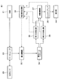
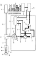
図1は本発明に係る計測システムを示すブロック図、図2は図1に示した計測システムの構成例を示す図である。図に示すように、光源21、サーキュレータ23、光学センサ25、偏光調整器30、偏光ビームスプリッタ34、第1、第2の光検出器35、36、差動増幅器37、ロックインアンプ38、表示部44および制御信号処理部39を有している。光源21からサーキュレータ23、サーキュレータ23から光学センサ25、サーキュレータ23から偏光調整器30までの偏光を保持するため、それぞれを接続するファイバとして偏波保持ファイバ(Polarization-maintaining fiber;PMF)22、24、29を用いている。また、偏光調整器30の出力ファイバとしては偏波保持ファイバ32を用いている。光学センサ25はレンズ26、光学結晶27、ミラー28、誘電体管45を有している。なお、被測定物理量により使用する光学結晶27は異なり、電界を測定するときはCdTe、ZnTe、DASTなどの電気光学結晶を用い、磁界を測定するときはYIGや希薄磁性半導体(DMS)などの磁気光学結晶を用い、音圧を測定するときは水晶やTe02結晶などの光弾性結晶を用いる。
FIG. 1 is a block diagram showing a measurement system according to the present invention, and FIG. 2 is a diagram showing a configuration example of the measurement system shown in FIG. As shown in the figure, a
光源21から出射された光源出力直線偏光は、偏波保持ファイバ22、24によってサーキュレータ23を経由して光学結晶27に伝送され、たとえば光学結晶27において瞬時印加電界によって偏光変調された偏光変調光は偏波保持ファイバ24に再入射され、偏波保持ファイバ24、29により偏波モード分散を重畳されて、サーキュレータ23により偏光信号処理ユニット46の偏光調整器30に伝送される。偏光調整器30に伝送された偏光変調光は偏光調整器30により直線偏光や楕円偏光などの任意偏光に変換される。また、偏光調整器30の応答速度が被測定電界の変位速度よりも大きいと、被測定電界により偏光変調された偏光信号が打ち消されてしまう。このため、偏光調整器30により任意偏光に変換する速度を光学結晶27を介して光源出力直線偏光が被測定物理量によって偏光変調される速度よりも十分遅くする。すなわち、偏光調整器30の応答周波数を被測定物理量の振動周波数に比べて小さくする。なお、偏光調整器30の応答速度は被測定物理量によって異なる。マイクロ波以上の電磁界を計測するときの偏光調整器30の応答周波数は300MHz以下でなければならず、VHF以上の電磁界を計測するときには30MHz以下でなければならず、超音波を計測するときは20kHz以下でなければならない。計測システムにおいて偏光調整器30が対象とする偏光変化は、偏波保持ファイバ24、29の長さによって決定される偏波モード分散の重畳、光学結晶27に入射される光源出力直線偏光の軸ずれによる偏波面の回転、偏波保持ファイバ24、29の温度変化や曲げ応力に起因する偏光変化である。
The light source output linearly polarized light emitted from the
偏光調整器30は1/2波長板、1/4波長板、波長板を回転するモータ31を有している。波長板の回転動作によって偏光軸が傾く、移動するなどのことがないように、モータ31としてはリニア駆動のモータもしくはエアベアリングを使用したモータを用いるのが好ましい。また、波長板の回転角度精度は約1°以下が必要であり、無限回転が可能であることが好ましい。また、簡易的にモータ31を制御するのにGP−IBが有用であるが、高速制御が要求される場合、直接制御回路が必要である。
The
偏光調整器30から出力された任意偏光は偏光ビームスプリッタ34により直交するp偏光(第1の分離直線偏光)とs偏光(第2の分離直線偏光)とに分離される。なお、図1、図2に示した計測システムにおいては、偏光調整器30の出力ファイバ32からの空間伝搬光をレンズ33によりコリメートした後、偏光ビームスプリッタ34に入射しているが、ファイバ型や光導波路型の偏光ビームスプリッタを用いるときには、偏光調整器30と偏光ビームスプリッタ、偏光ビームスプリッタと光検出器35、36を光ファイバで接続することができる。この場合、光ファイバは偏波保持ファイバ、シングルモードファイバ(SMF)のいずれでもよく、軸合わせの容易なシングルモードファイバとする方が安価となる。
The arbitrary polarized light output from the
偏光ビームスプリッタ34により分離されたp偏光およびs偏光は、被測定電界の振幅に応じて互いに逆相に変動する強度変調光として、それぞれ光検出器35、36によって光電変換され、光検出器35、36から電気信号が出力される。なお、光検出器35、36は被測定物理量の変動周波数よりも高い周波数まで十分な変換効率を有していなければならない。
The p-polarized light and the s-polarized light separated by the
差動増幅器37は光検出器35、36から電気信号を入力して、光検出器35、36から電気信号の差に比例した信号を出力する。この差動増幅器37の出力信号は被測定電界に比例した信号であり、ロックインアンプ38によって検出される。すなわち、差動信号はロックインアンプ38により被測定物理量の振幅信号と位相信号として出力される。
The
光検出器35、36の第1、第2の光電流Ip1、Ip2とロンクインアンプ38からの振幅信号(強度信号)Vとが信号線40〜42を介して制御信号処理部39に入力され、制御信号処理部39は光電流Ip1、Ip2が等しくかつ振幅信号Vが最大となるように信号線43を介してモータ31を制御することにより偏光調整器30を制御して任意偏光を調節する。
The first and second photocurrents I p1 and I p2 of the
図3は光検出器35、36の規格化された出力電気信号V1(t)およびV2(t)、差動増幅器37の規格化された出力電気信号△V(t)を示している。ここでtは時間を表す。偏光変調光が偏光調整器30によって円偏光に保たれている場合には、出力電気信号V1(t)、V2(t)の波形はそれぞれ図3(a)、(b)に示されるようになり、出力電気信号△V(t)の波形は図3(c)に示されるように振幅が十分大きくDC成分はゼロになる。もし、偏光調整器30を使わない場合には、偏光変調光はファイバ内でランダムに偏光状態が変化し、一般に出力電気信号V1(t)、V2(t)の波形はそれぞれ図3(d)、(e)に示すようになり、出力電気信号△V(t)の波形は図3(f)に示すように振幅が小さくなる。また、出力電気信号△V(t)の波形にはDC成分が存在するので、差動増幅器37が飽和し正常に動作しなくなるばかりか、雑音が大きくなるというデメリットが生じる。
FIG. 3 shows the standardized output electrical signals V 1 (t) and V 2 (t) of the
すなわち、光検出器35、36の光電流Ip1、Ip2を一致させたときには、図3(a)、(b)に示すように、出力電気信号V1(t)、V2(t)のDC電圧を一致させることができる。光検出器35、36の光電流Ip1、Ip2は入力光による励起電流の平均値であるため、DC電圧として参照することが可能である。DC電圧が一致することにより、差動増幅器37の雑音レベルが最小になる。この光電流Ip1、Ip2の参照においては、偏光ビームスプリッタ34において分割される偏光の量が一致しているだけであり、偏光調整器30により直線偏光や楕円偏光に調整されている可能性がある。このため、ロックインアンプ38からの振幅信号Vを参照して、偏光調整器30により円偏光を形成するようにすなわち振幅信号が最大なるように偏波を調整すれば、差動増幅器37から出力される信号が最大になり、SN比が最大となって、常に最大の感度が得られる。
That is, when the photocurrents I p1 and I p2 of the
このように、図1、図2に示した計測システムにおいては、常に最大の感度が得られるから、光学センサ25を動かすことによって偏波保持ファイバ24にかかる応力が変化し、偏光変調光にランダムな偏光変化が加わったとしても、最大の感度で被測定物理量を計測することが可能になる。また、偏光調整器30により任意偏光に変換する速度を光学結晶27を介して光源出力直線偏光が被測定物理量によって偏光変調される速度よりも十分遅くしているから、被測定電界等の被測定物理量により偏光変調された偏光信号が打ち消されてしまうことがなく、被測定物理量を確実に計測することができる。
As described above, in the measurement system shown in FIGS. 1 and 2, the maximum sensitivity is always obtained. Therefore, when the
なお、CW光源を用いて正弦振動する被測定物理量を計測する場合、ミリ波帯やTHz帯などの高い周波数で変化する被測定物理量やパルス状に繰り返される被測定物理量を測定するとき、光検出器35、36や差動増幅器37の帯域が足らないため、被測定物理量を正確に測定することができない。そこで、光源出力直線偏光を被測定物理量の振動周波数の正数分の1の周波数で強度変調した後、偏波保持ファイバ22に入射し、ロックインアンプ38が差動信号の変調周波数の成分を出力し、偏光調整器30の応答周波数を差動信号の変調周波数に比べて小さくすれば、被測定物理量を正確に測定することができる。また、光源出力直線偏光を被測定物理量の振動周波数の正数分の1の周波数と上記周波数に比べて小さいビート周波数とを加えた周波数で強度変調した後、偏波保持ファイバ22に入射し、ロックインアンプ38が差動信号のビート周波数の成分を出力し、偏光調整器30の応答周波数をビート周波数に比べて小さくすれば、被測定物理量を正確に測定することができる。なお、強度変調光は光検出器35、36の注入電流を変調する直接変調により容易に得られる。また、強度変調器を用いてCW光を強度変調する外部変調により発生させることもできる。しかし、変調器に入力できる光量が制限されるため、後段に光増幅器が必要になるなど、システムが複雑になる。このような強度変調光を用いて測定する場合、偏光変調器30の応答周波数を差動信号の変調周波数よりも小さくする。例えば、10kHzのビート周波数を用いる場合、偏光変調器30の応答周波数を10kHzよりも小さく設定する。
When measuring a measured physical quantity that sine vibrates using a CW light source, when measuring a measured physical quantity that changes at a high frequency, such as a millimeter wave band or a THz band, or a measured physical quantity that is repeated in a pulsed manner, light detection is performed. Since the bandwidths of the
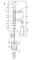
なお、上述実施の形態においては、偏光調整器として1/2波長板、1/4波長板、波長板を回転するモータ31を有する偏光調整器30を用いたが、偏光調整器は光ファイバと光ファイバの外径方向に圧力を加える機構によっても構成することができる。光ファイバの外径方向に圧力を加えると、圧力が加えられた方向とその方向と直交する方向の光弾性定数の差が生じて、複屈折が発生する。お互いに45°傾いた3方向から圧力を加えることによって、それぞれ直交する偏光に対して360°(1波長)以上の偏波モード分散を与えることができ、偏光を無限に回転することができる。複屈折の大きさは加えられた圧力に比例するが、ある圧力を超えると光ファイバが破損するため、さらに45°ずらした4方向から圧力を加えて偏光を回転させることが実用的である。
In the above-described embodiment, the
また、上述実施の形態においては、偏光調整器30の出力ファイバとして偏波保持ファイバ32を用いたが、偏光調整器の出力ファイバとしてシングルモードファイバを用いてもよい。また、上述実施の形態においては、電気信号測定器としてロックインアンプ38を用いたが、電気信号測定器としてスペクトラムアナライザ、オシロスコープなどを用いてもよい。
Further, in the above-described embodiment, the
21…光源
22…偏波保持ファイバ
23…サーキュレータ
24…偏波保持ファイバ
27…光学結晶
29…偏波保持ファイバ
30…偏波保持ファイバ
34…偏光ビームスプリッタ
35…第1の光検出器
36…第2の光検出器
37…差動増幅器
38…ロックインアンプ
39…制御信号処理部
DESCRIPTION OF
Claims (4)
Priority Applications (1)
| Application Number | Priority Date | Filing Date | Title |
|---|---|---|---|
| JP2004110753A JP4875835B2 (en) | 2004-04-05 | 2004-04-05 | Measuring system |
Applications Claiming Priority (1)
| Application Number | Priority Date | Filing Date | Title |
|---|---|---|---|
| JP2004110753A JP4875835B2 (en) | 2004-04-05 | 2004-04-05 | Measuring system |
Publications (2)
| Publication Number | Publication Date |
|---|---|
| JP2005292068A true JP2005292068A (en) | 2005-10-20 |
| JP4875835B2 JP4875835B2 (en) | 2012-02-15 |
Family
ID=35325145
Family Applications (1)
| Application Number | Title | Priority Date | Filing Date |
|---|---|---|---|
| JP2004110753A Expired - Fee Related JP4875835B2 (en) | 2004-04-05 | 2004-04-05 | Measuring system |
Country Status (1)
| Country | Link |
|---|---|
| JP (1) | JP4875835B2 (en) |
Cited By (1)
| Publication number | Priority date | Publication date | Assignee | Title |
|---|---|---|---|---|
| JP2007226560A (en) * | 2006-02-23 | 2007-09-06 | Nippon Telegr & Teleph Corp <Ntt> | IC card system |
Families Citing this family (1)
| Publication number | Priority date | Publication date | Assignee | Title |
|---|---|---|---|---|
| WO2019066050A1 (en) * | 2017-09-29 | 2019-04-04 | シチズンファインデバイス株式会社 | Magnetic sensor element and magnetic sensor device |
-
2004
- 2004-04-05 JP JP2004110753A patent/JP4875835B2/en not_active Expired - Fee Related
Cited By (1)
| Publication number | Priority date | Publication date | Assignee | Title |
|---|---|---|---|---|
| JP2007226560A (en) * | 2006-02-23 | 2007-09-06 | Nippon Telegr & Teleph Corp <Ntt> | IC card system |
Also Published As
| Publication number | Publication date |
|---|---|
| JP4875835B2 (en) | 2012-02-15 |
Similar Documents
| Publication | Publication Date | Title |
|---|---|---|
| US5113131A (en) | Voltage measuring device having electro-optic sensor and compensator | |
| US6563589B1 (en) | Reduced minimum configuration fiber optic current sensor | |
| JP2619981B2 (en) | Electromagnetic field strength measuring device | |
| US7859666B2 (en) | Electric field sensor | |
| Stokes et al. | Sensitive all-single-mode-fiber resonant ring interferometer | |
| JP2015230163A (en) | Photovoltage measuring device | |
| US20090212763A1 (en) | Optical sensor, optical current sensor and optical voltage sensor | |
| JP4875835B2 (en) | Measuring system | |
| JPS63241440A (en) | Method and device for measuring frequency response of optical detector | |
| Tao et al. | Dual closed-loop control method for resonant integrated optic gyroscopes with combination differential modulation | |
| JP2007057324A (en) | Optical fiber type measurement system | |
| WO2020153322A1 (en) | Electric field sensor | |
| US7102757B2 (en) | Current measurement method and device based on a fiber optic in-line Sagnac interferometer | |
| JP3210957B2 (en) | Semiconductor laser light frequency modulation device and interference measurement device using the same | |
| JP3549813B2 (en) | High frequency electromagnetic wave detection system and high frequency electromagnetic wave detection method | |
| CN116678389A (en) | Resonant Fiber Optic Gyroscope Based on Broadband Light Source | |
| Yu et al. | Limitation of rotation sensing in IORG by Rayleigh backscattering noise | |
| CA2380696A1 (en) | Reduced minimum configuration fiber opic current sensor | |
| JPH07243940A (en) | Polarization dependent loss measuring method and apparatus | |
| JP2672414B2 (en) | Reference signal generator for lock-in amplifier | |
| JPH02232620A (en) | Laser light source apparatus | |
| JP3301324B2 (en) | Optical voltage / electric field sensor | |
| JP6586186B1 (en) | Wavelength sweep light source, OFDR apparatus using the same, and measurement method | |
| JP3015903B2 (en) | Integrated circuit circuit test apparatus and circuit test method | |
| JP2006266711A (en) | Sensitive highly stable electric field sensor using electro-optic effect |
Legal Events
| Date | Code | Title | Description |
|---|---|---|---|
| A621 | Written request for application examination |
Free format text: JAPANESE INTERMEDIATE CODE: A621 Effective date: 20060905 |
|
| A131 | Notification of reasons for refusal |
Free format text: JAPANESE INTERMEDIATE CODE: A131 Effective date: 20090414 |
|
| RD02 | Notification of acceptance of power of attorney |
Free format text: JAPANESE INTERMEDIATE CODE: A7422 Effective date: 20090518 |
|
| RD04 | Notification of resignation of power of attorney |
Free format text: JAPANESE INTERMEDIATE CODE: A7424 Effective date: 20090518 |
|
| A521 | Request for written amendment filed |
Free format text: JAPANESE INTERMEDIATE CODE: A523 Effective date: 20090612 |
|
| A02 | Decision of refusal |
Free format text: JAPANESE INTERMEDIATE CODE: A02 Effective date: 20100202 |
|
| A521 | Request for written amendment filed |
Free format text: JAPANESE INTERMEDIATE CODE: A523 Effective date: 20111014 |
|
| A01 | Written decision to grant a patent or to grant a registration (utility model) |
Free format text: JAPANESE INTERMEDIATE CODE: A01 |
|
| A61 | First payment of annual fees (during grant procedure) |
Free format text: JAPANESE INTERMEDIATE CODE: A61 Effective date: 20111128 |
|
| FPAY | Renewal fee payment (event date is renewal date of database) |
Free format text: PAYMENT UNTIL: 20141202 Year of fee payment: 3 |
|
| R150 | Certificate of patent or registration of utility model |
Free format text: JAPANESE INTERMEDIATE CODE: R150 |
|
| S531 | Written request for registration of change of domicile |
Free format text: JAPANESE INTERMEDIATE CODE: R313531 |
|
| R350 | Written notification of registration of transfer |
Free format text: JAPANESE INTERMEDIATE CODE: R350 |
|
| LAPS | Cancellation because of no payment of annual fees |