JP2005292012A - Surface analyzer - Google Patents
Surface analyzer Download PDFInfo
- Publication number
- JP2005292012A JP2005292012A JP2004109566A JP2004109566A JP2005292012A JP 2005292012 A JP2005292012 A JP 2005292012A JP 2004109566 A JP2004109566 A JP 2004109566A JP 2004109566 A JP2004109566 A JP 2004109566A JP 2005292012 A JP2005292012 A JP 2005292012A
- Authority
- JP
- Japan
- Prior art keywords
- probe
- cantilever
- sample
- electron beam
- analysis apparatus
- Prior art date
- Legal status (The legal status is an assumption and is not a legal conclusion. Google has not performed a legal analysis and makes no representation as to the accuracy of the status listed.)
- Withdrawn
Links
Images
Landscapes
- Analysing Materials By The Use Of Radiation (AREA)
Abstract
【課題】本発明が解決しようとする問題点は、試料面において、光電子を励起できる強度のX線をμm程度に収束させるのが限界であったという点である。
【解決手段】試料に対向する導電性探針を有するカンチレバーと、前記カンチレバーの前記探針部分に電子線を照射する電子線源と、前記探針から発生したX線により前記試料から発生した荷電粒子を捕集して分光する分光器を備えた表面分析装置であって、前記電子線が前記カンチレバーの探針反対面に照射する表面分析装置。
【選択図】 図1
The problem to be solved by the present invention is that the limit of focusing X-rays with an intensity capable of exciting photoelectrons on the sample surface to about μm.
A cantilever having a conductive probe facing the sample, an electron beam source for irradiating the probe portion of the cantilever with an electron beam, and a charge generated from the sample by X-rays generated from the probe. A surface analyzer comprising a spectroscope that collects and separates particles, wherein the electron beam irradiates the probe opposite surface of the cantilever.
[Selection] Figure 1
Description
本発明は微小領域からのX線励起による光電子分光を行う表面分析装置に関する。 The present invention relates to a surface analyzer that performs photoelectron spectroscopy by X-ray excitation from a minute region.
光電子分光装置は、1次励起線であるX線を試料表面に照射し、その照射により試料から放出される光電子を電子分光器で分析してエネルギースペクトルを得る装置である。この得られたスペクトルを解析することによって、試料表面の元素およびその元素の化学状態を知ることができる。 A photoelectron spectrometer is an apparatus that obtains an energy spectrum by irradiating a sample surface with X-rays, which are primary excitation rays, and analyzing photoelectrons emitted from the sample with an electron spectrometer. By analyzing the obtained spectrum, the element surface and the chemical state of the element can be known.
特に微小な領域を分析するマイクロ光電子分光装置では、X線を試料に上へ収束照射するためにキャピラリ管を用いたり、X線レンズを用いたりすることが行われている。X線を収束することは難しく、大規模なレンズ構造を取らなければ実現できないことが多い。しかし、微小領域に照射するためには細いX線を近くから照射することが望ましいが、大規模なレンズ構造では試料近傍に配置できず、遠くから強い強度のX線を照射していた。このため、数μm程度に収束させるのが限界であった。 In particular, in a micro photoelectron spectrometer that analyzes a minute region, a capillary tube or an X-ray lens is used to converge and irradiate a sample with X-rays. Converging X-rays is difficult and often cannot be achieved without taking a large-scale lens structure. However, in order to irradiate a minute region, it is desirable to irradiate thin X-rays from near, but in a large-scale lens structure, it cannot be arranged near the sample, and X-rays with strong intensity are radiated from a distance. For this reason, it was the limit to converge to about several micrometers.
なお、従来技術としては、導体の探針に電子線を照射し、そこから発生したX線によって励起された光電子を測定するX線微小分析法がある(例えば、特許文献1)。しかし、この方法では、横方向から探針の側面に電子線が照射されるため、乱反射等の影響により良好な分析結果が得られなかった。 As a conventional technique, there is an X-ray microanalysis method in which a probe tip of a conductor is irradiated with an electron beam and photoelectrons excited by X-rays generated therefrom are measured (for example, Patent Document 1). However, in this method, since the electron beam is irradiated to the side surface of the probe from the lateral direction, a good analysis result cannot be obtained due to the influence of irregular reflection or the like.
本発明が解決しようとする問題点は、試料面において、光電子を励起できる強度のX線をμm程度に収束させるのが限界であったという点である。 The problem to be solved by the present invention is that the limit on the sample surface is to converge X-rays with such intensity that can excite photoelectrons to about μm.
請求項1の発明は、試料に対向する導電性探針を有するカンチレバーと、前記カンチレバーの前記探針部分に電子線を照射する電子線源と、前記探針から発生したX線により前記試料から発生した荷電粒子を捕集して分光する分光器を備えた表面分析装置であって、前記電子線が前記カンチレバーの探針反対面に照射される表面分析装置である。 According to a first aspect of the present invention, there is provided a cantilever having a conductive probe facing the sample, an electron beam source for irradiating the probe portion of the cantilever with an electron beam, and X-rays generated from the probe from the sample. The surface analysis apparatus includes a spectroscope that collects and separates the generated charged particles and irradiates the surface opposite to the probe of the cantilever with the electron beam.
請求項2の発明は、前記探針が中空の錐であり、前記カンチレバーの探針反対面が金属コーティングされている請求項1に記載された表面分析装置である。
The invention according to
請求項3の発明は、前記探針が先端に穴を有する中空の錐であり、前記金属コーティングにより前記穴が塞がれている請求項2に記載された表面分析装置である。
The invention according to
請求項4の発明は、前記金属コーティングがアルミコーティングである請求項2又は3に記載された表面分析装置である。
The invention according to claim 4 is the surface analysis apparatus according to
請求項5の発明は、前記探針と前記試料との距離を調整する距離調整手段を備えた請求項1乃至4のいずれかに記載された表面分析装置である。 A fifth aspect of the present invention is the surface analysis apparatus according to any one of the first to fourth aspects, further comprising distance adjusting means for adjusting a distance between the probe and the sample.
請求項6の発明は、前記探針と前記試料を相対的に走査させる走査手段を備えた請求項1乃至5のいずれかに記載された表面分析装置である。 A sixth aspect of the present invention is the surface analysis apparatus according to any one of the first to fifth aspects, further comprising scanning means for relatively scanning the probe and the sample.
本発明により、細くて弱いX線を近くから照射することができ、試料面において、光電子を励起できる強度のX線を数百nmに収束させることを実現した。 According to the present invention, it was possible to irradiate thin and weak X-rays from near, and to converge X-rays having an intensity capable of exciting photoelectrons on the sample surface to several hundred nm.
以下、発明を実施するための最良の形態により、本発明を詳細に説明する。 Hereinafter, the present invention will be described in detail according to the best mode for carrying out the invention.
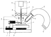
本発明の構成を図を用いて説明する。図1は表面分析装置の正面断面図である。構成としては、従来技術であるオージェ電子分光装置において、電子励起用の電子線光軸11上にアルミニウムコーティングされたカンチレバー3の探針部分を挿入したものである。分析室1は図示しない排気装置により超高真空に排気されている。分析室1内部にはベース5が設置されており、ベース5上にはXYステージ4が設置されている。XYステージ4上には試料2が交換自在に置載されている。
The configuration of the present invention will be described with reference to the drawings. FIG. 1 is a front sectional view of the surface analysis apparatus. As a configuration, in the Auger electron spectrometer which is a conventional technique, a probe portion of an aluminum-coated
また、ベース5にはカンチレバー挿脱機構6が設置されている。カンチレバー挿脱機構6にはZサーボ7が設置されており、Zサーボ7には試料2に対向してカンチレバー3が設置されている。
The
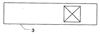
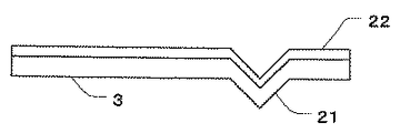
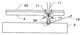
ここで、図2はカンチレバーの平面図であり、図3はカンチレバー正面の断面図である。カンチレバー3はSiO2で構成されており、先端に中空(無開口)の四角錐状の探針21がエッチングにより形成されている。探針21は従来の原子間力顕微鏡用探針と同等の形状であり、先端部の曲率は100nm以下に形成されている。カンチレバー3背面にはアルミニウムコーティング22が蒸着されている。アルミニウム等の物質に数十KeVのエネルギーを持った電子線を照射するとその物質を構成している原子に特有の特性X線が発生する。一般的なX線管で用いられるターゲット金属は、アルミニウム、ジルコニウム、銅、モリブテンが良く用いられるが、カンチレバー3に蒸着する材料としてはアルミニウムが最適である。
Here, FIG. 2 is a plan view of the cantilever, and FIG. 3 is a sectional view of the front surface of the cantilever. The
さらに、図1において、試料2上方には、偏向器10、電子レンズ9、電子銃8等から構成される電子照射系12が配置されている。電子照射系12の光軸は探針21上に位置している。
Further, in FIG. 1, an
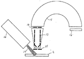
また、試料2上方右側には、試料2に対向してインプットレンズ系13が配置されている。インプットレンズ系13は静電レンズより構成されており、続いて、スリット14、アナライザ15及び検出器16等が設置されている。また、検出器16には図示しない制御装置が接続され、データを処理する。
An
以上、図における各部の構成について説明したが、次に動作について説明する。電子銃8より放出された電子は電子レンズ9により収束され、カンチレバー3背面の探針21中空部に照射される。電子が探針21のアルミニウムコーティング22部に照射されることにより、探針21先端より特性X線17(AlKα線)が発生する。X線17は電子11が照射された部分から四方八方に放出される。光電子を励起するにはある程度の強度のX線が必要であが、発生源から距離が離れるほど強度が低下し、発散する。図5に示すように、探針21は試料2から数μmに接近しているため、試料2の励起部分28は直径数百nm〜数μmとなる。
The configuration of each unit in the figure has been described above. Next, the operation will be described. The electrons emitted from the electron gun 8 are converged by the
探針21先端と試料2表面間の距離は、接触状態から数μmの範囲でZサーボ7により移動自在であり、X線17の状態により調整できる。また、試料2はXYステージに置載されており、XYステージを移動させることにより試料2の任意の位置にX線17を照射することができる。
The distance between the tip of the
このように試料2における直径数百nm〜数μmの励起部分28で発生した光電子18は分光器前段のインプットレンズ系13によって捕捉される。光電子18はインプットレンズ系13により収束及び減速されてスリット14を通過する。スリット14を通過した光電子18は、アナライザ15でエネルギー分析される。そして、アナライザ15で選別された光電子18は検出器16で検出される。検出器16は、検出した光電子18を電気信号に変換して出力し、その電気信号は図示しない制御装置に取り込まれる。制御装置は、取り込んだ信号から光電子スペクトルを生成し、そのスペクトルを図示しない表示装置に表示する。
Thus, the
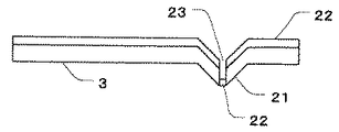
なお、本発明は、上記実施の形態に限定されるものではなく、種々の変形が可能である。例えば、カンチレバーは図4のように、探針21先端が開口している走査型近接場光学顕微鏡用カンチレバーを用いてもよい。カンチレバーはアルミニウムコーティング23されたSiO2で構成されており、カンチレバー先端に四角錐状の探針21が形成されている。探針21は中空で、先端の開口部23にはアルミニウムコーティング23を再蒸着して塞いである。この場合、X線は探針の先端部分からのみ発生するため、指向性が高い。
In addition, this invention is not limited to the said embodiment, A various deformation | transformation is possible. For example, the cantilever may be a cantilever for a scanning near-field optical microscope having an open tip at the
また、カンチレバー3背面のコーティングは、ジルコニウム、銅、モリブテン等の金属でもよい。
Further, the coating on the back surface of the
実施例2は、マッピングを行う場合であり、構成は実施例1の図1と同様である。 The second embodiment is a case where mapping is performed, and the configuration is the same as that of FIG.
この場合、XYステージ4により試料2を移動させ、試料2のX線17が照射する位置を順次ずらして測定を行い、各測定データを図示しない制御装置のメモリに保持し、各位置での元素を色に対応させてマッピングを行うことができる。
In this case, the
なお、本発明は、上記実施の形態に限定されるものではなく、種々の変形が可能である。例えば、試料2を移動させる代わりに照射するX線を移動させてもよい。この場合、偏向器10により電子線光軸11の照射位置を順次ずらすとともに、カンチレバー3の位置を電子線光軸11の位置に合わせて移動させる。
In addition, this invention is not limited to the said embodiment, A various deformation | transformation is possible. For example, instead of moving the
1 分析室
2 試料
3 カンチレバー
4 XYステージ
5 ベース
6 カンチレバー挿脱機構
7 Zサーボ
8 電子銃
9 電子レンズ
10 偏向器
11 電子線光軸
12 電子照射系
13 インプットレンズ系
14 スリット
15 アナライザ
16 検出器
17 X線
18 光電子
21 探針
22 アルミニウムコーティング
23 開口部
25 スリット
26 X線源
27 X線
28 励起部分
DESCRIPTION OF
Claims (6)
前記カンチレバーの前記探針部分に電子線を照射する電子線源と、
前記探針から発生したX線により励起された前記試料から発生した荷電粒子を捕集して分光する分光器を備えた表面分析装置であって、
前記電子線が前記カンチレバーの探針反対面に照射される表面分析装置。 A cantilever having a conductive probe facing the sample;
An electron beam source for irradiating the probe portion of the cantilever with an electron beam;
A surface analyzer comprising a spectroscope for collecting and spectroscopically collecting charged particles generated from the sample excited by X-rays generated from the probe,
A surface analysis apparatus in which the electron beam is irradiated to the probe opposite surface of the cantilever.
前記カンチレバーの探針反対面が金属コーティングされている請求項1に記載された表面分析装置。 The probe is a hollow cone;
The surface analysis apparatus according to claim 1, wherein a surface opposite to the probe of the cantilever is coated with metal.
前記金属コーティングにより前記穴が塞がれている請求項2に記載された表面分析装置。 The probe is a hollow cone having a hole at the tip,
The surface analysis apparatus according to claim 2, wherein the hole is closed by the metal coating.
The surface analysis apparatus according to claim 1, further comprising a scanning unit that relatively scans the probe and the sample.
Priority Applications (1)
| Application Number | Priority Date | Filing Date | Title |
|---|---|---|---|
| JP2004109566A JP2005292012A (en) | 2004-04-02 | 2004-04-02 | Surface analyzer |
Applications Claiming Priority (1)
| Application Number | Priority Date | Filing Date | Title |
|---|---|---|---|
| JP2004109566A JP2005292012A (en) | 2004-04-02 | 2004-04-02 | Surface analyzer |
Publications (1)
| Publication Number | Publication Date |
|---|---|
| JP2005292012A true JP2005292012A (en) | 2005-10-20 |
Family
ID=35325092
Family Applications (1)
| Application Number | Title | Priority Date | Filing Date |
|---|---|---|---|
| JP2004109566A Withdrawn JP2005292012A (en) | 2004-04-02 | 2004-04-02 | Surface analyzer |
Country Status (1)
| Country | Link |
|---|---|
| JP (1) | JP2005292012A (en) |
Cited By (3)
| Publication number | Priority date | Publication date | Assignee | Title |
|---|---|---|---|---|
| JP2010243377A (en) * | 2009-04-08 | 2010-10-28 | Mitsubishi Electric Corp | Scanning probe photoelectron yield spectroscopy microscopy and scanning probe photoelectron yield spectroscopy microscope |
| JP2013518269A (en) * | 2010-01-29 | 2013-05-20 | コミッサリア ア レネルジー アトミーク エ オ ゼネルジ ザルタナテイヴ | Electronic control and amplification device for local piezoelectric power measurement probe subject to particle beam |
| WO2014174997A1 (en) * | 2013-04-22 | 2014-10-30 | 東京エレクトロン株式会社 | Cantilever, manufacturing process, detection device, and detection method |
-
2004
- 2004-04-02 JP JP2004109566A patent/JP2005292012A/en not_active Withdrawn
Cited By (3)
| Publication number | Priority date | Publication date | Assignee | Title |
|---|---|---|---|---|
| JP2010243377A (en) * | 2009-04-08 | 2010-10-28 | Mitsubishi Electric Corp | Scanning probe photoelectron yield spectroscopy microscopy and scanning probe photoelectron yield spectroscopy microscope |
| JP2013518269A (en) * | 2010-01-29 | 2013-05-20 | コミッサリア ア レネルジー アトミーク エ オ ゼネルジ ザルタナテイヴ | Electronic control and amplification device for local piezoelectric power measurement probe subject to particle beam |
| WO2014174997A1 (en) * | 2013-04-22 | 2014-10-30 | 東京エレクトロン株式会社 | Cantilever, manufacturing process, detection device, and detection method |
Similar Documents
| Publication | Publication Date | Title |
|---|---|---|
| US11087955B2 (en) | System combination of a particle beam system and a light-optical system with collinear beam guidance, and use of the system combination | |
| US7718979B2 (en) | Particle-optical apparatus for simultaneous observing a sample with particles and photons | |
| JP5342728B2 (en) | Collection of secondary electrons through the objective lens of a scanning electron microscope | |
| US6777674B2 (en) | Method for manipulating microscopic particles and analyzing | |
| JP2003149185A (en) | Sample observation apparatus and method using electron beam | |
| Goldstein et al. | Scanning electron microscope (SEM) instrumentation | |
| CN108666192B (en) | Charged particle beam device | |
| EP1956632A1 (en) | Particle-optical apparatus for simultaneous observing a sample with particles and photons | |
| CN114113185A (en) | Imaging method for realizing zoom scanning of scanning electron microscope | |
| JP2005098909A (en) | Ionizer and mass spectrometer using the same | |
| JP2004513477A (en) | SEM with adjustable final electrode for electrostatic objective | |
| EP1754049A2 (en) | Method for manipulating microscopic particles and analyzing the composition thereof | |
| JP2023051853A (en) | Method and system for elemental mapping | |
| US20160254120A1 (en) | Near-field Optical Transmission Electron Emission Microscope | |
| US20070210249A1 (en) | Electron Spectroscope With Emission Induced By A Monochromatic Electron Beam | |
| JP2005292012A (en) | Surface analyzer | |
| JP7042971B2 (en) | Holder and charged particle beam device | |
| CN114252653A (en) | Ultrafast imaging device and method thereof | |
| US9024275B2 (en) | Specimen holder for charged-particle beam apparatus | |
| JP2000304712A (en) | Electron beam analyzer / observer and electron beam micro analyzer | |
| KR20030050320A (en) | Method and apparatus for inspecting semiconductor substrate | |
| JP2005528735A (en) | Apparatus for measuring X-ray radiation generated by an object exposed to an electron beam | |
| JP2000215841A (en) | Compound emission electron microscope for chemical analysis | |
| Suri | Detection and Analysis of Low Energy Electrons in a Scanning Electron Microscope using a novel detector design based on the Bessel Box Energy Analyser | |
| JP2000329716A (en) | Auger electron spectrometer and depth direction analysis method |
Legal Events
| Date | Code | Title | Description |
|---|---|---|---|
| A300 | Withdrawal of application because of no request for examination |
Free format text: JAPANESE INTERMEDIATE CODE: A300 Effective date: 20070605 |
