JP2005291964A - Dimension measuring structure and tool box with dimension measuring structure - Google Patents
Dimension measuring structure and tool box with dimension measuring structure Download PDFInfo
- Publication number
- JP2005291964A JP2005291964A JP2004108341A JP2004108341A JP2005291964A JP 2005291964 A JP2005291964 A JP 2005291964A JP 2004108341 A JP2004108341 A JP 2004108341A JP 2004108341 A JP2004108341 A JP 2004108341A JP 2005291964 A JP2005291964 A JP 2005291964A
- Authority
- JP
- Japan
- Prior art keywords
- measurement
- dimension
- measured
- recess
- forming surface
- Prior art date
- Legal status (The legal status is an assumption and is not a legal conclusion. Google has not performed a legal analysis and makes no representation as to the accuracy of the status listed.)
- Pending
Links
Images
Landscapes
- Length-Measuring Instruments Using Mechanical Means (AREA)
Abstract
【課題】 パイプ,ボルト若しくは板材等の被測定物の径や厚さを、例えばメジャー等の測定工具を工具箱から出し入れすることなく容易に測定することができ、これにより、秀れた作業性を発揮することができ、また、簡易な構成にして容易に設計実現可能であるため、コスト安に実現することができるこれまでにない極めて実用性に秀れる寸法測定構造を提供すること。
【解決手段】 パイプ,ボルト,ナット若しくは板材等の被測定物1の寸法を測定する寸法測定構造であって、異なる径若しくは異なる厚さに夫々合致する異なる寸法の測定凹部2を複数並設状態に形成表面3に凹設し、この各測定凹部2にこの測定凹部2の寸法を示す表示部4を並設し、この複数の測定凹部2のうちから前記被測定物1の径若しくは厚さに係合合致し得る測定凹部2を選択しこれに対応する表示部4を読み取ることで、前記被測定物1の径若しくは厚さを測定し得るように構成した寸法測定構造。
【選択図】 図1
PROBLEM TO BE SOLVED: To easily measure the diameter and thickness of an object to be measured such as a pipe, a bolt or a plate material without putting a measuring tool such as a measure in and out of a tool box. In addition, it is possible to provide a dimension measurement structure that is extremely practical and unprecedented that can be realized at a low cost because it can be easily realized with a simple configuration.
A dimension measuring structure for measuring a dimension of an object to be measured 1 such as a pipe, a bolt, a nut, or a plate material, wherein a plurality of measuring recesses 2 having different dimensions respectively matching different diameters or different thicknesses are arranged side by side. The display surface 4 indicating the dimension of the measurement recess 2 is provided in parallel with each measurement recess 2, and the diameter or thickness of the object 1 to be measured is selected from the plurality of measurement recesses 2. A dimension measurement structure configured to measure the diameter or thickness of the DUT 1 by selecting the measurement recess 2 that can be engaged and matched and reading the display unit 4 corresponding thereto.
[Selection] Figure 1
Description
本発明は、パイプ,ボルト,ナット若しくは板材等の被測定物1の寸法を測定する寸法測定構造に関するものである。 The present invention relates to a dimension measuring structure for measuring the dimension of an object 1 to be measured such as a pipe, bolt, nut or plate.
工事現場や建築現場などにおいて、パイプ,ボルト,ナット若しくは板材等の被測定物の径や厚さを測定する場合には、所定の測定工具を使用して測定するが、例えばパイプやボルトの径を測定する場合には、ノギスを使用し、このノギスでパイプを挟持することで、この挟持した際の目盛りを読み取って、パイプの外径を測定している。 When measuring the diameter and thickness of objects to be measured such as pipes, bolts, nuts, or plate materials at construction sites and construction sites, etc., measure them using a specified measuring tool. Is measured, the caliper is used, and the pipe is clamped with the caliper, and the scale at the time of clamping is read to measure the outer diameter of the pipe.
ところで、パイプ等の被測定物の径や厚さを測定する度に、工具箱からノギス等の測定工具を出し入れするのは非常に煩わしいといえる。 By the way, it can be said that it is very troublesome to put a measuring tool such as a caliper in and out of the tool box every time the diameter or thickness of the measured object such as a pipe is measured.
即ち、もしパイプや板材等の被測定物の径や厚さの測定を、その都度、工具箱からノギス等の測定工具を取り出すことなく、また、ノギス等の測定工具を所定操作したりすることなく行うことができれば、作業性を非常に向上させることができる。 That is, if the diameter or thickness of the object to be measured, such as pipes or plates, is measured, the measuring tool such as a caliper is not removed from the tool box each time, and the measuring tool such as a caliper is operated in a predetermined manner. If it can be performed without any problems, workability can be greatly improved.
本発明は、パイプ,ボルト若しくは板材等の被測定物の径や厚さを、例えばメジャー等の測定工具を工具箱から出し入れし且つ所定操作することなく容易に測定することができ、これにより、秀れた作業性を発揮することができ、また、簡易な構成にして容易に設計実現可能であり、しかも、コスト安に実現することができるこれまでにない極めて実用性に秀れる寸法測定構造を提供することを目的としている。 The present invention can easily measure the diameter and thickness of an object to be measured such as a pipe, a bolt, or a plate material without taking a measuring tool such as a measure out of a tool box and performing a predetermined operation. Dimensional measurement structure that can demonstrate excellent workability, can be easily designed with a simple configuration, and can be realized at low cost. The purpose is to provide.
添付図面を参照して本発明の要旨を説明する。 The gist of the present invention will be described with reference to the accompanying drawings.
パイプ,ボルト,ナット若しくは板材等の被測定物1の寸法を測定する寸法測定構造であって、異なる径若しくは異なる厚さに夫々合致する異なる寸法の測定凹部2を複数並設状態に形成表面3に凹設し、この各測定凹部2にこの測定凹部2の寸法を示す表示部4を並設し、この複数の測定凹部2のうちから前記被測定物1の径若しくは厚さに係合合致し得る測定凹部2を選択しこれに対応する表示部4を読み取ることで、前記被測定物1の径若しくは厚さを測定し得るように構成したことを特徴とする寸法測定構造に係るものである。 A dimension measuring structure for measuring the dimension of an object to be measured 1 such as a pipe, bolt, nut, or plate material, wherein a plurality of measuring recesses 2 each having a different diameter or different thickness are formed in parallel. In each of the measurement recesses 2, display portions 4 indicating the dimensions of the measurement recesses 2 are provided in parallel, and the diameter or thickness of the object to be measured 1 is engaged with each other from the plurality of measurement recesses 2. According to the dimension measuring structure, the diameter or thickness of the DUT 1 can be measured by selecting the measurement recess 2 that can be measured and reading the display unit 4 corresponding thereto. is there.
また、前記形成表面3に、前記被測定物1が係合合致するに十分な浅い凹部を形成して前記測定凹部2を形成したことを特徴とする請求項1記載の寸法測定構造に係るものである。
2. The dimension measuring structure according to claim 1, wherein the measurement concave portion 2 is formed by forming a shallow concave portion sufficient to engage and match the device under test 1 on the forming
また、前記形成表面3を樹脂成形する際に、前記測定凹部2を一体成形して形成したことを特徴とする請求項1,2のいずれか1項に記載の寸法測定構造に係るものである。
Moreover, when the said
また、前記被測定物1となる板材の板厚を測定する寸法測定構造であって、異なる板厚に夫々合致する異なる巾寸法の前記測定凹部2となるスリット凹部2Bを複数並設状態に前記形成表面3に凹設したことを特徴とする請求項1〜3のいずれか1項に記載の寸法測定構造に係るものである。
Further, it is a dimension measuring structure for measuring the plate thickness of the plate material to be measured 1, and a plurality of slit recesses 2B to be the measurement recesses 2 having different width dimensions respectively matching different plate thicknesses are arranged in parallel. The dimensional measurement structure according to claim 1, wherein the dimensional measurement structure is recessed in the forming
また、前記形成表面3に段差角縁8を形成し、この段差角縁8に沿って前記スリット凹部2Bを複数並設状態に設けると共に、この段差角縁8を凹設して形成表面3に対して斜設状態に形成したことを特徴とする請求項4記載の寸法測定構造に係るものである。
In addition, a step angle edge 8 is formed on the forming
また、前記形成表面3を工具箱5の外面としたことを特徴とする請求項1〜5のいずれか1項に記載の寸法測定構造に係るものである。
Moreover, the said
また、前記測定凹部2の寸法を示すシール部材6を前記形成表面3に付設して前記表示部4を設けたことを特徴とする請求項1〜6のいずれか1項に記載の寸法測定構造に係るものである。
The dimension measuring structure according to claim 1, wherein a seal member 6 indicating the dimension of the measurement recess 2 is attached to the forming
また、前記形成表面3にシール付設用凹部9を形成し、このシール付設用凹部9に前記シール部材6を付設し、前記形成表面3と面一状態若しくはこれより凹設した状態で前記シール部材6を付設して前記表示部4を設けたことを特徴とする請求項1〜7のいずれか1項に記載の寸法測定構造に係るものである。
In addition, a concave portion 9 with a seal is formed on the forming
また、前記形成表面3に長さ目盛り若しくは分度器目盛りを設けた目盛シール部材7を付設したことを特徴とする請求項1〜8のいずれか1項に記載の寸法測定構造に係るものである。
The dimension measuring structure according to any one of claims 1 to 8, wherein a scale seal member 7 provided with a length scale or a protractor scale is attached to the forming
また、前記請求項1〜9のいずれか1項に記載の寸法測定構造を、前記形成表面3を開閉蓋10の表面として施したことを特徴とする工具箱に係るものである。
Further, the present invention relates to a tool box characterized in that the dimension measuring structure according to any one of claims 1 to 9 is applied with the forming
本発明は上述のように構成したから、パイプ,ボルト若しくは板材等の被測定物の径や厚さを、例えばメジャー等の測定工具を工具箱から出し入れし且つ所定操作することなく容易に測定することができ、これにより、秀れた作業性を発揮することができ、また、簡易な構成にして容易に設計実現可能であり、しかも、コスト安に実現することができるこれまでにない極めて実用性に秀れる寸法測定構造となる。 Since the present invention is configured as described above, the diameter and thickness of an object to be measured such as a pipe, bolt, or plate material can be easily measured without putting a measuring tool such as a measure in and out of the tool box and performing a predetermined operation. This makes it possible to demonstrate excellent workability, can be easily designed with a simple configuration, and can be realized at a low cost. It becomes a dimension measurement structure with excellent properties.
即ち、例えば単に形成表面に凹設した異なる寸法の測定凹部の中から、被測定物に係合合致する測定凹部を選択してこの測定凹部に並設した表示部の数値を読み取るだけで、被測定物の径若しくは厚さを測定することができる極めて実用性に秀れる寸法測定構造となる。 That is, for example, by simply selecting a measurement recess that engages and matches the object to be measured from measurement recesses of different dimensions provided on the forming surface, and reading the numerical value of the display unit arranged in parallel with the measurement recess, It becomes a dimension measurement structure excellent in practicality that can measure the diameter or thickness of the measurement object.
また、請求項2記載の発明においては、前記測定凹部の形成を簡易に行うことができる極めて実用性に秀れる寸法測定構造となる。 Moreover, in the invention according to claim 2, it becomes a dimension measurement structure excellent in practicality that can easily form the measurement recess.
また、請求項3記載の発明においては、形成表面の成形と共に前記測定凹部を形成することが可能となり、よって、効率良く測定凹部を形成することができる極めて実用性に秀れた寸法測定構造となる。
Further, in the invention according to
また、請求項4記載の発明においては、このスリット凹部のうち板材の厚さに係合合致し得るスリット凹部を選択してこのスリット凹部に対応する表示部を読み取ることで、板材の厚さを良好に測定することができる極めて実用性に秀れた寸法測定構造となる。 Further, in the invention according to claim 4, by selecting a slit concave portion that can be engaged and matched with the thickness of the plate material from among the slit concave portions, and reading the display portion corresponding to the slit concave portion, the thickness of the plate material is reduced. It becomes a dimension measurement structure excellent in practicality that can be measured well.
また、請求項5記載の発明においては、例えば板材をやや傾斜させつつスリット凹部に係合し得るように構成すれば、スリット凹部の形成長さが板材の一辺の長さを超える場合であっても、板材を傾斜させてこの板材の縁の一部をスリット凹部に容易に係合できるため、スリット凹部を小スペースで形成しても、即ち、スリット凹部の形成長さを短めに設定しても、板材の板厚を確実に測定することができる極めて実用性に秀れた寸法測定構造となる。 Further, in the invention according to claim 5, for example, if the plate material is configured to be able to engage with the slit recess while being slightly inclined, the formation length of the slit recess exceeds the length of one side of the plate material. However, since the plate material can be inclined and a part of the edge of the plate material can be easily engaged with the slit recess, even if the slit recess is formed in a small space, that is, the length of the slit recess is set to be short. However, it is a dimension measurement structure with excellent practicality that can reliably measure the thickness of the plate material.
また、請求項6記載の発明においては、工具箱を開け閉めすることなく、前記被測定物の径若しくは厚さを容易に測定できることとなり、また、必要に応じて所定の工具を速やかに取り出すことも可能となる極めて実用性に秀れた寸法測定構造となる。 In the invention described in claim 6, the diameter or thickness of the object to be measured can be easily measured without opening and closing the tool box, and a predetermined tool can be quickly taken out as necessary. It is possible to achieve a dimension measurement structure with excellent practicality.
また、請求項7記載の発明においては、単にシール部材を付設するだけで複数の測定凹部の各々の寸法を表示できることとなり、よって、簡易に表示部を形成することができる極めて実用性に秀れた寸法測定構造となる。 Further, in the invention described in claim 7, it is possible to display the dimensions of each of the plurality of measurement recesses simply by attaching a seal member. Therefore, the display unit can be easily formed and is extremely practical. Dimension measurement structure.
また、請求項8記載の発明においては、前記測定凹部の各々の寸法を表示したシール部材を形成表面と面一状態若しくは形成表面よりも内部位置に付設することが可能となり、これにより、シール部材を非常に剥がれにくい状態で形成表面に付設することができる極めて実用性に秀れた寸法測定構造となる。 Further, in the invention according to claim 8, it is possible to attach the seal member indicating the dimensions of each of the measurement recesses in a state of being flush with the forming surface or at an internal position with respect to the forming surface. Can be attached to the forming surface in a state where it is very difficult to peel off, resulting in a highly practical dimension measuring structure.
また、請求項9記載の発明においては、前記形成表面において被測定部材の長さや例えば折曲角度を容易に測定することができる極めて実用性に秀れた寸法測定構造となる。 In the invention according to claim 9, the dimension measurement structure is excellent in practicality and can easily measure the length of the member to be measured and, for example, the bending angle on the formation surface.
また、請求項10記載の発明においては、請求項1〜9記載の発明の作用効果を良好に発揮し得る極めて実用性に秀れた工具箱となる。
Moreover, in the invention of
好適と考える本発明の実施形態(発明をどのように実施するか)を、図面に基づいて本発明の作用を示して簡単に説明する。 Embodiments of the present invention that are considered suitable (how to carry out the invention) will be briefly described with reference to the drawings, illustrating the operation of the present invention.
形成表面3に複数並設状態に凹設された異なる径若しくは異なる厚さに夫々合致する異なる寸法の測定凹部2のうちから、パイプ,ボルト,ナット若しくは板材等の被測定物1の径若しくは厚さに係合合致し得る測定凹部2を選択し、この選択した測定凹部2に対応する表示部4を読み取ることで、前記被測定物1の径若しくは厚さを測定できることとなる。
The diameter or thickness of the object to be measured 1 such as a pipe, bolt, nut, or plate material from among the measurement recesses 2 having different sizes respectively corresponding to different diameters or different thicknesses recessed in the
即ち、例えば被測定物1を測定する度に工具箱からノギス等の測定工具を取り出したりしまったりせずとも、単に形成表面3に凹設した異なる寸法の測定凹部2に被測定物1を係合させ、その中から径若しくは厚さが合致する測定凹部2を選択してこの測定凹部2に並設した表示部4の数値を読み取るだけで、被測定物1の径若しくは厚さを測定できることとなる。
That is, for example, without measuring a measuring tool such as a vernier caliper from the tool box each time the measured object 1 is measured, the measured object 1 is simply engaged with the measurement recesses 2 of different dimensions provided in the forming
また、形成表面3に測定凹部2を設けたことで、被測定物1を係合合致し易く、よって、スムーズな測定を行えることとなる。
Further, by providing the measurement concave portion 2 on the forming
従って、本発明は、ノギス等の測定工具を用いずとも形成表面3に形成した測定凹部2のうちから被測定物1に係合合致する測定凹部2を選択してこの測定凹部2に対応する表示部4を読み取るだけで前記被測定物1の径若しくは厚さを簡易に測定することができる極めて実用性に秀れた寸法測定構造となる。
Therefore, the present invention selects the measurement recess 2 that engages and matches the object to be measured 1 from the measurement recesses 2 formed on the forming
また、例えば、前記形成表面3に、前記被測定物1が係合合致するに十分な浅い凹部を形成することで前記測定凹部2を形成すれば、前記測定凹部2の形成を簡易に行えることとなるなど、一層実用的となる。
Further, for example, if the measurement recess 2 is formed by forming a shallow recess sufficient to engage and match the device under test 1 on the forming
また、例えば、前記形成表面3を樹脂成形する際に、前記測定凹部2を一体成形して形成すれば、形成表面3の成形と共に前記測定凹部2を形成することが可能となり、よって、効率良く測定凹部2を形成できることとなるなど、一層実用的となる。
Further, for example, when the forming
また、例えば、前記被測定物1となる板材の板厚を測定し得る異なる板厚に夫々合致する異なる巾寸法の前記測定凹部2となるスリット凹部2Bを複数並設状態に前記形成表面3に凹設すれば、このスリット凹部2Bのうち板材の厚さに係合合致し得るスリット凹部2Bを選択してこのスリット凹部2Bに対応する表示部4を読み取ることで、板材の厚さを良好に測定できることとなるなど、一層実用的となる。
In addition, for example, a plurality of slit recesses 2B serving as the measurement recesses 2 having different width dimensions respectively matching different plate thicknesses capable of measuring the plate thickness of the plate material serving as the object to be measured 1 are arranged on the forming
また、例えば、前記形成表面3に段差角縁8を形成し、この段差角縁8に沿って前記スリット凹部2Bを複数並設状態に設けると共に、この段差角縁8を凹設して形成表面3に対して斜設状態に形成すれば、例えば一辺が長い板材であっても小スペースで形成したスリット凹部2Bによって板材の板厚を測定できることとなる。
Further, for example, a step angle edge 8 is formed on the forming
即ち、例えばスリット凹部2Bを平坦部位に所定長さ形成した場合には、板材の一辺の長さが前記スリット凹部2Bの形成長さを超える場合には、スリット凹部2Bに板材を係合させにくくなるため、板材の厚さを測定しにくくなる。 That is, for example, when the slit recess 2B is formed to have a predetermined length in a flat portion, if the length of one side of the plate exceeds the formation length of the slit recess 2B, it is difficult to engage the plate with the slit recess 2B. Therefore, it becomes difficult to measure the thickness of the plate material.
この点、段差角縁8にスリット凹部2Bを斜設すれば、即ち、板材をやや傾斜させつつスリット凹部2Bに係合し得るように構成すれば、スリット凹部2Bの形成長さが板材の一辺の長さを超える場合であっても、板材を傾斜させてこの板材の縁の一部をスリット凹部2Bに容易に係合できるため、スリット凹部2Bを小スペースで形成しても、即ち、スリット凹部2Bの形成長さを短めに設定しても、板材の板厚を確実に測定できることとなるなど、一層実用的となる。 In this regard, if the slit concave portion 2B is obliquely provided at the stepped corner edge 8, that is, if the plate material is configured to be able to engage with the slit concave portion 2B while being slightly inclined, the formation length of the slit concave portion 2B is one side of the plate material. Even if the length of the plate is exceeded, the plate material can be inclined and a part of the edge of the plate material can be easily engaged with the slit recess 2B. Therefore, even if the slit recess 2B is formed in a small space, that is, the slit Even if the formation length of the concave portion 2B is set to be short, the plate thickness of the plate material can be reliably measured, and thus it becomes more practical.
また、例えば、前記形成表面3を工具箱5の外面とすれば、工具箱5を開け閉めすることなく、前記被測定物1の径若しくは厚さを測定できることとなり、また、必要に応じて所定の工具を速やかに取り出すことも可能となるなど、一層実用的となる。
Further, for example, if the forming
また、例えば、前記測定凹部2の寸法を示すシール部材6を前記形成表面3に付設して前記表示部4を設ければ、単にシール部材6を付設するだけで複数の測定凹部2の各々の寸法を表示できることとなり、よって、簡易に表示部4を形成できることとなるなど、一層実用的となる。
Further, for example, if the seal member 6 indicating the dimension of the measurement recess 2 is attached to the forming
また、例えば、前記形成表面3にシール付設用凹部9を形成し、このシール付設用凹部9に前記シール部材6を付設し、前記形成表面3と面一状態若しくはこれより凹設した状態で前記シール部材6を付設して前記表示部4を設ければ、前記測定凹部2の各々の寸法を表示したシール部材6を形成表面3と面一状態若しくは形成表面3よりも内部位置に付設することが可能となり、これにより、シール部材6を非常に剥がれにくい状態で形成表面3に付設できることとなるなど、一層実用的となる。
Further, for example, a concave portion 9 with a seal is formed on the forming
また、例えば、前記形成表面3に長さ目盛り若しくは分度器目盛りを設けた前記シール部材6を付設すれば、前記形成表面3において被測定部材1の長さや例えば折曲角度を容易に測定できることとなるなど、一層実用的となる。
For example, if the sealing member 6 provided with a length scale or a protractor scale is attached to the forming
また、例えば、前記請求項1〜9のいずれか1項に記載の寸法測定構造を、前記形成表面3を開閉蓋10の表面として施せば、前記作用効果を良好に発揮し得る工具箱5を実現できることとなるなど、一層実用的となる。
For example, if the dimension measurement structure according to any one of claims 1 to 9 is applied as the surface of the opening / closing
本発明の具体的な実施例について図面に基づいて説明する。 Specific embodiments of the present invention will be described with reference to the drawings.
本実施例は、パイプ,ボルト,ナット若しくは板材等の被測定物1の寸法を測定する寸法測定構造に関するものであって、異なる径若しくは異なる厚さに夫々合致する異なる寸法の測定凹部2を複数並設状態に形成表面3に凹設し、この各測定凹部2にこの測定凹部2の寸法を示す表示部4を並設し、この複数の測定凹部2のうちから前記被測定物1の径若しくは厚さに係合合致し得る測定凹部2を選択しこれに対応する表示部4を読み取ることで、前記被測定物1の径若しくは厚さを測定し得るように構成したものである。
This embodiment relates to a dimension measuring structure for measuring the dimension of an object to be measured 1 such as a pipe, bolt, nut, or plate material, and includes a plurality of measuring recesses 2 having different dimensions respectively matching different diameters or different thicknesses. A concave portion is formed on the forming
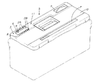
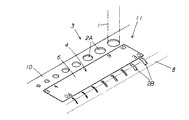
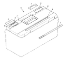
本実施例は、図1に示すように、形成表面3を工具箱5の開閉蓋10の表面3としてこの開閉蓋10の表面に前記寸法測定構造を施したものである。
In this embodiment, as shown in FIG. 1, the
即ち、開閉蓋10の表面3に露出状態で、異なる径若しくは異なる厚さに夫々合致する異なる寸法の測定凹部2を複数並設状態に凹設している。
In other words, a plurality of measurement recesses 2 having different diameters or different thicknesses are provided in a juxtaposed manner in an exposed state on the
この測定凹部2は、パイプ,ボルト,ナット若しくは板材等の被測定部材1を係合合致するに十分な浅い凹部に設定している。即ち、この凹部の浅さは、被測定部材1となる例えばパイプの端部を係合させて所定の測定凹部2に合致したことを視認できるか若しくは合致した感触を得られる程度に設定している。 The measurement recess 2 is set as a shallow recess sufficient to engage and match the member 1 to be measured such as a pipe, bolt, nut, or plate. That is, the shallowness of the concave portion is set to such an extent that the end of the pipe that becomes the member to be measured 1 is engaged, for example, so that it can be visually confirmed that a predetermined measurement concave portion 2 is matched or a matching feel is obtained. Yes.
具体的には、図1,図2に示すように、測定凹部2として、パイプ,ボルト若しくはナット等の径を測定し得る平面視円形状の円形凹部2Aと板材の板厚を測定し得るスリット凹部2Bとを設けた構成としている。 Specifically, as shown in FIGS. 1 and 2, as the measurement recess 2, a circular recess 2 </ b> A that can measure the diameter of a pipe, bolt, nut, or the like, and a slit that can measure the plate thickness of the plate material. The recess 2B is provided.
更に具体的には、円形凹部2Aは、一方側へ向かう程、前記円形凹部2Aの径が大きくなるように、即ち、他方側へ向かう程、前記円形凹部2Aの径が小さくなるように、複数並設状態に凹設している。 More specifically, the circular recess 2A has a plurality of diameters so that the diameter of the circular recess 2A increases toward the one side, that is, the diameter of the circular recess 2A decreases toward the other side. It is recessed in the juxtaposed state.
また、スリット凹部2Bも前記円形凹部2Aと同様、一方側へ向かう程、前記スリット凹部2Bの巾寸法が大きくなるように、即ち、他方側へ向かう程、前記スリット凹部2Bの巾寸法が小さくなるように複数並設状態に凹設している。 Similarly to the circular concave portion 2A, the slit concave portion 2B has a width dimension that increases toward the one side, that is, a width dimension of the slit concave portion 2B that decreases toward the other side. As shown in FIG.
また、スリット凹部2Bは、工具箱5の開閉蓋10に膨出部11を設けることで形成された段差角縁8に沿って複数並設状態に設けると共に、この段差角縁8を凹設して開閉蓋10の外面に対して斜設状態に形成した構成としている。
Further, the slit recess 2B is provided in a plurality of juxtaposed states along the step angle edge 8 formed by providing the bulging portion 11 on the opening / closing
具体的には、膨出部11は、開閉蓋10の長さ方向における左右側、即ち、図1における手前側及び奥側に設けている。
Specifically, the bulging portion 11 is provided on the left and right sides in the length direction of the opening / closing
そして、開閉蓋10の表面3にしてこの膨出部11の形成により立ち上がり形成される段差角縁8に、異なる板厚に夫々合致する異なる巾寸法の前記スリット凹部2Bを複数並設状態に凹設した構成としている。
Then, a plurality of slit recesses 2B having different width dimensions respectively corresponding to different plate thicknesses are recessed in the juxtaposed state on the stepped corner edge 8 formed upright by the formation of the bulging portion 11 on the
この膨出部11の段差角縁8にスリット凹部2Bを設けることで、このスリット凹部2Bを開閉蓋10の外面に対して斜設状態に設けることが可能となり、この斜設状態のスリット凹部2Bに板材の縁の一部を係合合致させるだけで、前記板厚を測定できることとなる。
By providing the slit concave portion 2B at the stepped corner edge 8 of the bulging portion 11, the slit concave portion 2B can be provided obliquely with respect to the outer surface of the opening / closing
これにより、たとえスリット凹部2Bの形成長さが板材の一辺の長さよりも極めて短かくても、板材の板厚を良好に測定することが可能となる。 Thereby, even if the formation length of the slit recess 2B is extremely shorter than the length of one side of the plate material, the plate thickness of the plate material can be measured well.
即ち、例えば、仮にスリット凹部2Bを平坦面に形成した場合には、このスリット凹部2Bの形成長さよりも長い板材は前記スリット凹部2Bに係合できないため、板厚を測定できないこととなる。 That is, for example, if the slit recess 2B is formed on a flat surface, a plate material longer than the length of the slit recess 2B cannot be engaged with the slit recess 2B, so that the plate thickness cannot be measured.
従って、膨出部11の段差角縁8を、板材が係合合致するに十分な浅い状態に凹設して短めのスリットを形成するだけで、簡易に板材の板厚を確実に測定できる前記スリット凹部2Bを形成することができる。 Therefore, the plate thickness of the plate material can be easily and reliably measured by simply forming the short slit by recessing the stepped corner edge 8 of the bulging portion 11 in a shallow state sufficient to engage and match the plate material. A slit recess 2B can be formed.
また、前記膨出部11は、開閉蓋10を補強する補強リブとしても機能している。そのため、開閉蓋10を補強する補強リブを利用して本実施例のスリット凹部2Bを形成できることとなる。
The bulging portion 11 also functions as a reinforcing rib that reinforces the opening / closing
円形凹部2Aとスリット凹部2Bとは、図1,図2に示すように、表示部4を介して対向状態に設けた構成としている。 As shown in FIGS. 1 and 2, the circular recess 2 </ b> A and the slit recess 2 </ b> B are configured to be opposed to each other via the display unit 4.
即ち、本実施例では、膨出部11の開閉蓋10中央寄りにスリット凹部2Bを設け、表示部4を介して開閉蓋10の外縁寄りに円形凹部2Aを設けた構成としている。
That is, in this embodiment, the slit concave portion 2B is provided near the center of the opening / closing
表示部4は、この表示部4に並設する前記円形凹部2A及び前記スリット凹部2Bの寸法を示すシール部材6を、前記円形凹部2Aと前記スリット凹部2Bとの間に付設することで設けた構成としている。 The display unit 4 is provided by attaching a seal member 6 indicating the dimensions of the circular recess 2A and the slit recess 2B arranged in parallel to the display unit 4 between the circular recess 2A and the slit recess 2B. It is configured.
具体的には、表示部4は、開閉蓋10の表面3にシール付設用凹部9を形成し、このシール付設用凹部9にシール部材6を付設することで設けた構成としている。
Specifically, the display unit 4 has a configuration in which a concave portion 9 with a seal is formed on the
これにより、シール付設用凹部9にシール部材6を付設するだけで、複数の測定凹部2に対応する寸法の表示を容易に設けることができる。 Thereby, the display of the dimension corresponding to the some measurement recessed part 2 can be easily provided only by attaching the sealing member 6 to the recessed part 9 with a seal | sticker.
また、シール付設用凹部9にシール部材6を付設することで、開閉蓋10の表面3と面一状態若しくは開閉蓋10の表面3よりも凹設した状態でシール部材6を付設でき、これにより、シール部材6を非常に剥がれにくい状態でシール付設用凹部9に付設することができる。
Further, by attaching the sealing member 6 to the concave portion 9 for attaching the seal, the sealing member 6 can be attached in a state of being flush with the
尚、シール部材6に表示された数値は、円形凹部2A若しくはスリット凹部2Bそのものの径若しくは厚さの数値を示すものではなく、前記円形凹部2A若しくはスリット凹部2Bに係合合致する被測定部材1の径若しくは厚さの数値を示すものである。 The numerical value displayed on the seal member 6 does not indicate the numerical value of the diameter or thickness of the circular concave portion 2A or the slit concave portion 2B itself, but the member to be measured 1 that is engaged and matched with the circular concave portion 2A or the slit concave portion 2B. The numerical value of the diameter or thickness is shown.
本実施例の開閉蓋10の表面3には、円形凹部2Aとスリット凹部2Bとの間以外にも、シール付設用凹部9を形成し、このシール付設用凹部9に所定の目盛りを形成した目盛シール部材7を付設した構成としている。
In addition to the space between the circular recess 2A and the slit recess 2B, a seal-providing recess 9 is formed on the
具体的には、開閉蓋10に形成した膨出部11にシール付設用凹部9を形成し、このシール付設用凹部9に長さ目盛りを設けた目盛シール部材7若しくは分度器目盛りを設けた目盛シール部材7を付設している。
Specifically, a seal-providing recess 9 is formed in the bulging portion 11 formed in the opening / closing
尚、本実施例では、シール付設用凹部9を膨出部11の二カ所に形成し、一方のシール付設用凹部9に長さ目盛りを設けた目盛シール部材7、他方のシール付設用凹部9に分度器目盛りを形成した目盛シール部材7を付設している。 In this embodiment, the seal-equipped recesses 9 are formed at two locations of the bulging portion 11, and the scale seal member 7 is provided with a length scale in one seal-provided recess 9 and the other seal-provided recess 9 A scale seal member 7 in which a protractor scale is formed is attached.
本実施例の工具箱5は樹脂製であり、この樹脂製の工具箱5(開閉蓋10)を樹脂成形する際に前記円形凹部2A,スリット凹部2B及びシール付設用凹部9を一体成形して形成している。 The tool box 5 of the present embodiment is made of resin, and when the resin tool box 5 (opening / closing lid 10) is resin-molded, the circular recess 2A, the slit recess 2B and the sealing recess 9 are integrally formed. Forming.
従って、前記円形凹部2A等をの形成を開閉蓋10の形成と共に簡易に行うことができ、よって、本実施例の作用効果を発揮し得る工具箱5を容易に製造することができる。
Accordingly, the formation of the circular recess 2A and the like can be easily performed together with the formation of the opening / closing
以上、本実施例は、開閉蓋10の表面3に複数凹設した円形凹部2A若しくはスリット凹部2Bの中から、パイプ,ボルト,ナット若しくは板材等の被測定部材1の径若しくは厚さに係合合致する前記円形凹部2A若しくはスリット凹部2Bを選択し、これに対応するシール部材6の表示を読み取るだけで、前記被測定部材1の径若しくは厚さを測定することができる。
As described above, the present embodiment engages with the diameter or thickness of the member 1 to be measured, such as a pipe, bolt, nut, or plate member, from the circular recess 2A or slit recess 2B formed in the
また、本実施例は、工具箱5の開閉蓋10の表面3に円形凹部2A及びスリット凹部2Bを設けたことで、被測定物1の径や厚さを測定する度に開閉蓋10を開け閉めしなくとも、工具箱5の開閉蓋10を閉めたままの状態で、被測定物1の径や厚さを容易に測定することができる。
Further, in this embodiment, a circular recess 2A and a slit recess 2B are provided on the
特に、スリット凹部2Bを、前述のように、膨出部11を設けることにより形成された段差角縁8に開閉蓋10の表面3に対して斜設状態に形成することで、被測定部材1となる板材を少し傾けることでスリット凹部2Bに係合させることが可能となり、よって、簡易に形成できるスリット凹部2Bによって板材の厚さを確実に測定することができる。
In particular, the slit concave portion 2B is formed obliquely with respect to the
尚、本発明は、本実施例に限られるものではなく、各構成要件の具体的構成は適宜設計し得るものである。 Note that the present invention is not limited to this embodiment, and the specific configuration of each component can be designed as appropriate.
1 被測定物
2 測定凹部
3 形成表面
4 表示部
5 工具箱
6 シール部材
DESCRIPTION OF SYMBOLS 1 Measured object 2 Measurement recessed
Claims (10)
A tool box, wherein the dimension measuring structure according to any one of claims 1 to 9 is provided with the forming surface as a surface of an opening / closing lid.
Priority Applications (1)
| Application Number | Priority Date | Filing Date | Title |
|---|---|---|---|
| JP2004108341A JP2005291964A (en) | 2004-03-31 | 2004-03-31 | Dimension measuring structure and tool box with dimension measuring structure |
Applications Claiming Priority (1)
| Application Number | Priority Date | Filing Date | Title |
|---|---|---|---|
| JP2004108341A JP2005291964A (en) | 2004-03-31 | 2004-03-31 | Dimension measuring structure and tool box with dimension measuring structure |
Publications (1)
| Publication Number | Publication Date |
|---|---|
| JP2005291964A true JP2005291964A (en) | 2005-10-20 |
Family
ID=35325048
Family Applications (1)
| Application Number | Title | Priority Date | Filing Date |
|---|---|---|---|
| JP2004108341A Pending JP2005291964A (en) | 2004-03-31 | 2004-03-31 | Dimension measuring structure and tool box with dimension measuring structure |
Country Status (1)
| Country | Link |
|---|---|
| JP (1) | JP2005291964A (en) |
Cited By (5)
| Publication number | Priority date | Publication date | Assignee | Title |
|---|---|---|---|---|
| JP2013253931A (en) * | 2012-06-08 | 2013-12-19 | Yahata Holdings Co Ltd | Screw discrimination tool |
| JP2013253929A (en) * | 2012-06-08 | 2013-12-19 | Yahata Holdings Co Ltd | Screw discrimination tool |
| JP2013253930A (en) * | 2012-06-08 | 2013-12-19 | Yahata Holdings Co Ltd | Screw discrimination tool |
| JP2017194387A (en) * | 2016-04-21 | 2017-10-26 | 株式会社ミツトヨ | Vernier caliper |
| JP2021012022A (en) * | 2019-07-03 | 2021-02-04 | 株式会社ディスコ | Measuring jig to measure the size of pipe fittings |
Citations (2)
| Publication number | Priority date | Publication date | Assignee | Title |
|---|---|---|---|---|
| JPS5786402U (en) * | 1980-11-18 | 1982-05-28 | ||
| JPH0496001U (en) * | 1990-12-12 | 1992-08-20 |
-
2004
- 2004-03-31 JP JP2004108341A patent/JP2005291964A/en active Pending
Patent Citations (2)
| Publication number | Priority date | Publication date | Assignee | Title |
|---|---|---|---|---|
| JPS5786402U (en) * | 1980-11-18 | 1982-05-28 | ||
| JPH0496001U (en) * | 1990-12-12 | 1992-08-20 |
Cited By (5)
| Publication number | Priority date | Publication date | Assignee | Title |
|---|---|---|---|---|
| JP2013253931A (en) * | 2012-06-08 | 2013-12-19 | Yahata Holdings Co Ltd | Screw discrimination tool |
| JP2013253929A (en) * | 2012-06-08 | 2013-12-19 | Yahata Holdings Co Ltd | Screw discrimination tool |
| JP2013253930A (en) * | 2012-06-08 | 2013-12-19 | Yahata Holdings Co Ltd | Screw discrimination tool |
| JP2017194387A (en) * | 2016-04-21 | 2017-10-26 | 株式会社ミツトヨ | Vernier caliper |
| JP2021012022A (en) * | 2019-07-03 | 2021-02-04 | 株式会社ディスコ | Measuring jig to measure the size of pipe fittings |
Similar Documents
| Publication | Publication Date | Title |
|---|---|---|
| US8404972B1 (en) | Electrical device mounting boxes | |
| US5567883A (en) | Bourdon tube pressure gauge having a removable cover | |
| WO2006076484A3 (en) | Periodic diffracting system for sample measurement | |
| HUP0102106A2 (en) | Reclosable pouring element and a flat gable composite packaging provided therewith | |
| JP7121493B2 (en) | Measuring tools and measuring tables | |
| US7392902B2 (en) | Suspension device which prevents a suspended tool from burglary | |
| US9080334B2 (en) | Recyclable formwork | |
| JP4399840B2 (en) | Tape measure with internal measurement jig | |
| US9329016B1 (en) | Weld gauge | |
| US7013737B2 (en) | Removable twisting measuring device for various hand tools | |
| ATE414888T1 (en) | POSITION SENSOR WITH MEASURING CABLE | |
| KR200370498Y1 (en) | Tray of CD-ROM drive | |
| JP3129490U (en) | Dimensional inspection jig | |
| JP5534283B1 (en) | Door latch device for automobile | |
| US20180054674A1 (en) | Portable noise measuring device and noise measuring method | |
| JP5084815B2 (en) | Sealing tool | |
| CN207358907U (en) | Positioning fixture | |
| CN206311026U (en) | Slide calliper rule cubing | |
| CN202748312U (en) | Test rack for testing reflectance spectrum of insects | |
| CN101858716B (en) | Coaxiality caliper | |
| JP2018112428A (en) | Wall thickness measuring tool, and wall thickness measurement method | |
| WO2008084555A1 (en) | Inspection system of repair record of automobile | |
| JP2004177379A (en) | Measuring instrument | |
| CN203838974U (en) | Sealing device for installing instrument in field | |
| KR200147105Y1 (en) | Precision measuring sphere of trunk lid for vehicle |
Legal Events
| Date | Code | Title | Description |
|---|---|---|---|
| A621 | Written request for application examination |
Effective date: 20070130 Free format text: JAPANESE INTERMEDIATE CODE: A621 |
|
| A131 | Notification of reasons for refusal |
Effective date: 20100415 Free format text: JAPANESE INTERMEDIATE CODE: A131 |
|
| A02 | Decision of refusal |
Free format text: JAPANESE INTERMEDIATE CODE: A02 Effective date: 20100805 |