JP2005291960A - Fuel cask storage device and storage method - Google Patents
Fuel cask storage device and storage method Download PDFInfo
- Publication number
- JP2005291960A JP2005291960A JP2004108312A JP2004108312A JP2005291960A JP 2005291960 A JP2005291960 A JP 2005291960A JP 2004108312 A JP2004108312 A JP 2004108312A JP 2004108312 A JP2004108312 A JP 2004108312A JP 2005291960 A JP2005291960 A JP 2005291960A
- Authority
- JP
- Japan
- Prior art keywords
- cask
- fuel
- storage
- fuel cask
- lid
- Prior art date
- Legal status (The legal status is an assumption and is not a legal conclusion. Google has not performed a legal analysis and makes no representation as to the accuracy of the status listed.)
- Pending
Links
Images
Classifications
-
- Y—GENERAL TAGGING OF NEW TECHNOLOGICAL DEVELOPMENTS; GENERAL TAGGING OF CROSS-SECTIONAL TECHNOLOGIES SPANNING OVER SEVERAL SECTIONS OF THE IPC; TECHNICAL SUBJECTS COVERED BY FORMER USPC CROSS-REFERENCE ART COLLECTIONS [XRACs] AND DIGESTS
- Y02—TECHNOLOGIES OR APPLICATIONS FOR MITIGATION OR ADAPTATION AGAINST CLIMATE CHANGE
- Y02E—REDUCTION OF GREENHOUSE GAS [GHG] EMISSIONS, RELATED TO ENERGY GENERATION, TRANSMISSION OR DISTRIBUTION
- Y02E30/00—Energy generation of nuclear origin
- Y02E30/30—Nuclear fission reactors
Landscapes
- Monitoring And Testing Of Nuclear Reactors (AREA)
Abstract
【課題】燃料キャスクの保管に際して、より充分な密封確保が図れるとともに、蓋部におけるシール部からの漏えい監視を素早く検知することが可能な燃料キャスク保管装置および同保管方法を提供する。
【解決手段】周壁部および底壁部が一体に構成され、上端部が開口する縦型円筒状のキャスク本体2と、このキャスク本体の上端開口部内に装着された一次蓋6aおよび二次蓋6bからなる二重蓋とを有し、内部収納物および充填気体の密封を保証する燃料キャスク1と、この燃料キャスクを倒立させた状態で下方から垂直に固定支持する貯蔵架台14とを備え、貯蔵架台は、保管場所の床上に固定配置される基台16と、この基台上に設けられ、下向きとなったキャスク本体2の下端部外周面を嵌合保持する保持枠17とを有し、燃料キャスクの貯蔵架台への保管状態において、基台の上面側と、保持枠の内周面側と、燃料キャスクの二次蓋下面側とに面する気密空間20が形成される。
【選択図】 図1Provided are a fuel cask storage device and a storage method capable of ensuring sufficient sealing when storing a fuel cask and capable of quickly detecting leakage monitoring from a seal portion in a lid portion.
A vertical cylindrical cask body 2 in which a peripheral wall portion and a bottom wall portion are integrally formed and an upper end portion is open, and a primary lid 6a and a secondary lid 6b mounted in the upper end opening portion of the cask body. A fuel cask 1 that guarantees the sealing of the internal contents and the filling gas, and a storage gantry 14 that is fixedly supported vertically from below while the fuel cask is inverted. The fuel cask has a base 16 fixedly arranged on the floor of the storage place, and a holding frame 17 provided on the base and fitting and holding the outer peripheral surface of the lower end portion of the cask main body 2 facing downward. In the storage state of the storage rack, an airtight space 20 is formed facing the upper surface side of the base, the inner peripheral surface side of the holding frame, and the lower surface side of the secondary lid of the fuel cask.
[Selection] Figure 1
Description
本発明は、核施設において使用された使用済燃料を収容して専用の場所まで搬送し、長期間の貯蔵に供する使用済燃料輸送貯蔵容器(本発明において、「燃料キャスク」という。)を保管するための燃料キャスク保管装置および同保管方法に関する。 The present invention stores a spent fuel transport storage container (referred to as “fuel cask” in the present invention) for storing spent fuel used in a nuclear facility, transporting it to a dedicated place, and providing it for long-term storage. The present invention relates to a fuel cask storage device and a storage method therefor.
燃料キャスクは、使用済燃料を数十年以上の長期間に亘ってノーメンテナンスで気密に保管するための容器であり、Heガスを充填した乾式キャスクとして構成され、内部収納物および充填気体の密封を保証する構成となっている。 A fuel cask is a container for storing spent fuel in an air-tight manner with no maintenance for a long period of several decades or more. The fuel cask is configured as a dry cask filled with He gas. It is the composition which guarantees.
図7は、このような従来の燃料キャスクの構成を示す縦断面図である。図7に示すように、燃料キャスク1は、縦型円筒状のキャスク本体2の外周側に中性子遮蔽体3を設け、キャスク本体2の上端の開口部4を介して所定本数の使用済燃料5を収容する構成となっている。
FIG. 7 is a longitudinal sectional view showing the structure of such a conventional fuel cask. As shown in FIG. 7, the
キャスク本体2の開口部4は、段差をもって小径な第1段開口部4aおよび大径な第2段開口部4bとして形成され、各開口部4a,4bにそれぞれ蓋6(小径な一次蓋6aおよび大径な二次蓋6b)によって二重に密封シールされる。一次蓋6aおよび二次蓋6bは、それぞれキャスク本体2に締結具10によって締結されている。
The opening 4 of the cask
各々の蓋6a,6bには、蓋用金属シール7a,7bが取付けられており、この蓋用金属シール7a,7bにより、密封確保(二重シール)が行われ、充分な安全管理がなされている。また、一次蓋6aと二次蓋6bとの間には、密閉された蓋間空間8が形成されている。
The
そして、保管時においては、密封境界の健全性確認およびシール部からの漏えい監視を目的として、燃料キャスク1ごとに、二次蓋6bに貫通孔を穿設して圧力変動検出装置をそれぞれ取付け、蓋間空間8の圧力を監視を行っている。
At the time of storage, for the purpose of confirming the soundness of the sealing boundary and monitoring leakage from the seal portion, for each
さらに、キャスク本体2の両端部近傍の外周面部には、例えば周方向に一定の間隔をあけて4個ずつのトラニオン9がそれぞれ設けられ、運搬時および保管時の支持が、これらのトラニオン9を介して行われている。
Further, for example, four
従来では、このような燃料キャスク1の保管について、横置きで保管する技術(特許文献1参照)、または縦置きで保管する技術(特許文献1参照)等が知られている。縦置きで保管する場合には、蓋側を上にして直立させる方式が考えられている。
燃料キャスクの保管に際しては、より充分な密封確保が必要であり、安全管理の一環として、蓋部におけるシール部からの漏えい監視を常時行い、素早く検知することが望まれる。また、燃料キャスクの密封境界の健全性を確認するための装置を取付ける手間の簡便化が望まれる。具体的には、密封境界の健全性確認用として、一次蓋と二次蓋とで形成する蓋間空間の圧力を監視するために、この空間まで二次蓋を穿孔し、二次蓋に圧力変動の検出装置を引き回していたものを、改善することが望ましい。そして、漏えい可能ルートの減少による信頼性の向上を図ることが望ましい。 When storing the fuel cask, it is necessary to ensure a sufficient seal, and as a part of safety management, it is desirable to always monitor and quickly detect leakage from the seal portion in the lid portion. In addition, it is desired to simplify the labor required for attaching a device for confirming the soundness of the sealing boundary of the fuel cask. Specifically, in order to check the soundness of the sealing boundary, in order to monitor the pressure in the space between the lid formed by the primary lid and the secondary lid, the secondary lid is drilled up to this space and the pressure is applied to the secondary lid. It would be desirable to improve what was leading around the fluctuation detector. It is desirable to improve reliability by reducing the number of leakable routes.
また、万一の漏えい発生を想定し、空間に放射性物質が流れ出ることを確実に防止できるようにすることが望ましい。さらに、サンプリング装置の簡便な接続構造および経済性の向上も望まれる。 It is also desirable to be able to reliably prevent the radioactive material from flowing into the space in the unlikely event of leakage. Furthermore, a simple connection structure of the sampling device and an improvement in economy are also desired.
さらに加えて、サンプリング装置について、放射性物質のみならず、圧力や温度等の多くの検出を行い、その漏えい検出の確率を、キャスク密封境界部を傷めることなく向上することも望まれる。 In addition, it is also desired to improve the probability of leak detection without damaging the cask sealing boundary by performing many detections of not only radioactive substances but also pressure, temperature, etc. for the sampling device.
本発明はこのような事情に鑑みてなされたもので、燃料キャスクの保管に際して、より充分な密封確保が図れるとともに、蓋部におけるシール部からの漏えい監視を素早く検知することが可能な燃料キャスク保管装置および同保管方法を提供することを目的とする。 The present invention has been made in view of such circumstances, and can store a fuel cask which can ensure sufficient sealing when storing the fuel cask and can quickly detect leakage monitoring from the seal portion in the lid portion. An object is to provide an apparatus and a storage method thereof.
また、本発明は、燃料キャスクの密封境界の健全性を確認するための装置を取付ける手間の簡便化が図れるとともに、漏えい可能ルートの減少による信頼性の向上が図れ、万一の漏えい発生時に対しても、空間に放射性物質が流れ出ることを確実に防止でき、安全性を一層向上できる燃料キャスク保管装置および同保管方法を提供することを目的とする。 In addition, the present invention simplifies the trouble of installing the device for confirming the soundness of the sealing boundary of the fuel cask and improves the reliability by reducing the number of leakable routes. However, it is an object of the present invention to provide a fuel cask storage device and a storage method that can reliably prevent a radioactive material from flowing into the space and can further improve safety.
さらに、本発明は、サンプリング装置の簡便化および経済性向上が図れるとともに、サンプリング装置について、放射性物質のみならず、圧力や温度等の多くの検出を行い、その漏えい検出の確率を、キャスク密封境界部を傷めることなく向上することができる燃料キャスク保管装置および同保管方法を提供することを目的とする。 Furthermore, the present invention can simplify the sampling device and improve the economical efficiency, and the sampling device can detect not only radioactive materials but also pressure, temperature, etc. An object of the present invention is to provide a fuel cask storage device and a storage method that can be improved without damaging the parts.
請求項1に係る発明では、周壁部および底壁部が一体に構成され、上端部が開口する縦型円筒状のキャスク本体と、このキャスク本体の上端開口部内に装着された一次蓋および二次蓋からなる二重蓋とを有し、内部収納物および充填気体の密封を保証する燃料キャスクと、この燃料キャスクを倒立させた状態で下方から垂直に固定支持する貯蔵架台とを備え、前記貯蔵架台は、保管場所の床上に固定配置される基台と、この基台上に設けられ、下向きとなった前記キャスク本体の下端部外周面を嵌合保持する保持枠とを有し、前記燃料キャスクの前記貯蔵架台への保管状態において、前記基台の上面側と、前記保持枠の内周面側と、前記燃料キャスクの二次蓋下面側とに面する気密空間が形成されることを特徴とする燃料キャスク保管装置を提供する。
In the invention which concerns on
なお、本発明においては、燃料キャスクの蓋側を下に向けた状態で貯蔵架台に装着し、トラニオンを貯蔵架台のキャスク支持部に搭載して固定し、倒立保持状態とすることが望ましい。 In the present invention, it is desirable to mount the fuel cask on the storage stand with the lid side facing downward, and to mount the trunnion on the cask support portion of the storage stand and fix it in an inverted holding state.
請求項2に係る発明では、前記キャスク本体の開口部側における周壁の外周面もしくは外端面と、前記保持枠の内周面側とに、前記燃料キャスク保管時に互いに接するシール溶接用突起をそれぞれ設け、これらシール溶接用突起同士の溶接部により、前記気密空間の上隅部を気密シールした燃料キャスク保管を提供する。
In the invention according to
請求項3に係る発明では、前記気密空間内の圧力を、前記燃料キャスク内の充填ガス圧力よりも低圧とした燃料キャスク保管装置を提供する。 According to a third aspect of the present invention, there is provided a fuel cask storage device in which the pressure in the airtight space is lower than the charging gas pressure in the fuel cask.
請求項4に係る発明では、前記保持枠を貫通して前記気密空間の内外を連通するサンプリング配管を備え、このサンプリング配管に、前記気密空間内の圧力、温度、気体の種類、および放射性物質の1以上を検出するサンプリング装置を接続した燃料キャスク保管装置を提供する。
In the invention which concerns on
請求項5に係る発明では、前記サンプリング装置は、検出データの定期的な取込み機能、または異常検出時に警報を出力する機能を備えた燃料キャスク保管装置を提供する。
In the invention which concerns on
請求項6に係る発明では、周壁部および底壁部が一体に構成され、上端部が開口する縦型円筒状のキャスク本体と、このキャスク本体の上端開口部内に装着された一次蓋および二次蓋からなる二重蓋とを有し、内部収納物および充填気体の密封を保証する燃料キャスクを、保管場所の床上に固定配置される基台に倒立状態で固定保持する燃料キャスク保管方法であって、前記燃料キャスクの下向きとなった前記二次蓋の下面側を囲む配置で気密空間を形成し、この気密空間内の圧力、温度、気体の種類、および放射性物質の1以上を検出しつつ、前記燃料キャスクを保管することを特徴とする燃料キャスク保管方法を提供する。
In the invention which concerns on
なお、本発明においては、シール溶接部を覆うように密閉カバーを設け、シール部の健全性を確認できるようにすることが望ましい。 In the present invention, it is desirable to provide a hermetic cover so as to cover the seal welding portion so that the soundness of the seal portion can be confirmed.
また、密封空間の圧力および漏洩放射性物質検知結果を常時監視するシステムを具備し、異常があった場合に警報を発するとともに、データを定期的に保存用計算機に取込み異常の診断および予防に役立てることが望ましい。 In addition, it is equipped with a system that constantly monitors the pressure in the sealed space and the detection results of leaking radioactive materials, and issues an alarm when there is an abnormality, and periodically takes the data into a storage computer to help diagnose and prevent the abnormality. Is desirable.
さらに、本発明においては、ガスサンプリングシステムを、貯蔵架台と別置きのユニットとすることが望ましい。 Furthermore, in the present invention, it is desirable that the gas sampling system is a unit separately from the storage stand.
本発明によれば、燃料キャスクを倒立させた状態で下方から垂直に固定支持する貯蔵架台を備え、この貯蔵架台によりキャスクの蓋部周囲下方を気密空間によって閉塞するようにすることで、燃料キャスクの保管に際し、より充分な密封確保が図れるとともに、蓋部におけるシール部からの漏えい監視を素早く検知することが可能となる。 According to the present invention, the fuel cask is provided with a storage stand that is fixedly supported vertically from below while the fuel cask is inverted. The fuel cask is closed by the airtight space around the lid portion of the cask by the storage stand. During storage, it is possible to secure a sufficient seal and to quickly detect leakage monitoring from the seal portion in the lid portion.
また、本発明によれば、蓋部周囲下方の気密空間に予め健全性を確認するための装置を取付けることができるので、従来のように二次蓋を穿孔する必要がなく、燃料キャスクの密封境界の健全性確認装置の取付け手間を簡便化することができる。 Further, according to the present invention, since a device for confirming the soundness can be attached in advance to the airtight space below the lid portion, there is no need to pierce the secondary lid as in the prior art, and the fuel cask is sealed. It is possible to simplify the installation work of the boundary soundness confirmation device.
また、この健全性確認装置は複数の気密空間に一括接続できる構造となるため、漏えい可能ルートの減少による信頼性の向上が図れるとともに、万一の漏えい発生時に対しても、空間に放射性物質が流れ出ることを確実に防止することができ、安全性の一層の向上が図れる。 In addition, since this soundness confirmation device has a structure that can be connected to a plurality of airtight spaces at the same time, the reliability can be improved by reducing the number of leakable routes, and in the event of a leak, there is no radioactive material in the space. Flowing out can be reliably prevented, and the safety can be further improved.
さらに、本発明によれば、サンプリング装置の簡便化および経済性向上が図れるとともに、サンプリング装置について、放射性物質のみならず、圧力や温度等の多くの検出を行い、その漏えい検出の確率を、キャスク密封境界部を傷めることなく向上することができる。 Furthermore, according to the present invention, the sampling device can be simplified and economically improved, and the sampling device can detect not only radioactive substances but also pressure, temperature, etc. This can be improved without damaging the sealing boundary.
以下、本発明に係る燃料キャスク保管装置および同方法の一実施形態について、図1〜図6を参照して説明する。なお、燃料キャスクの構成について、従来のものと同一または対応する部分には、図7と同一の符号を使用して説明する。 Hereinafter, an embodiment of a fuel cask storage device and method according to the present invention will be described with reference to FIGS. In addition, about the structure of a fuel cask, the same code | symbol as FIG. 7 is used and demonstrated about the part which is the same as that of a conventional thing, or respond | corresponds.
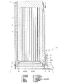
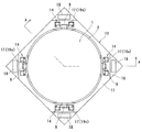
図1は、燃料キャスクを倒立状態で保管する燃料キャスク保管装置の基本構造を示す断面図(図2のA−A線断面図)であり、図2は同平面図である。図3は燃料キャスクを正立状態で示す縦断面図である。 FIG. 1 is a cross-sectional view (cross-sectional view taken along line AA in FIG. 2) showing a basic structure of a fuel cask storage device that stores a fuel cask in an inverted state, and FIG. 2 is a plan view of the same. FIG. 3 is a longitudinal sectional view showing the fuel cask in an upright state.
まず、燃料キャスクについて説明する。なお、本実施形態の燃料キャスク1は、全体的な構成においては、図7に示した従来の燃料キャスク1と略同様である。ただし、後述するように、シール溶接用突起11が設けられている点が、従来構成と異なっている。
First, the fuel cask will be described. The
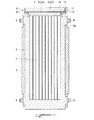
図3に示すように、燃料キャスク1は、縦型円筒状のキャスク本体2の周壁2aの外周側に中性子遮蔽体3を設け、キャスク本体2の上端の開口部4を介して所定本数の使用済燃料5を収容する構成となっている。使用済燃料5は、図示省略のバスケットにより保持されて、キャスク本体2内に収容される。
As shown in FIG. 3, the
キャスク本体2の開口部4は、段差をもって小径な第1段開口部4aおよび大径な第2段開口部4bとして形成され、各開口部4a,4bにそれぞれ蓋6(小径な一次蓋6aおよび大径な二次蓋6b)によって二重に密封シールされる。一次蓋6aおよび二次蓋6bは、それぞれキャスク本体2に締結具10によって締結されている。
The
各々の蓋6a,6bには、蓋用金属シール7a,7bが取付けられており、この蓋用金属シール7a,7bにより、密封確保(二重シール)が行われるようになっている。すなわち、内部収納物および充填気体の密封を保証する燃料キャスクとして構成され、充分な安全管理がなされるようになっている。また、一次蓋6aと二次蓋6bとの間には、密閉された蓋間空間8が形成されている。さらに、キャスク本体2の両端部近傍の外周面部には、例えば周方向に一定の間隔をあけて4個ずつのトラニオン9がそれぞれ設けられている。
The
このような構成において、本実施形態の燃料キャスク1においては、キャスク本体2の開口部3側における周壁2aの外周面、例えば二次蓋6aの内面高さの近傍に対応する外周面に、保管時における気密空間形成のため、シール溶接用突起としてのリップ11が形成されている。このシール溶接用リップ11は、キャスク本体2の周壁2aの外面に周方向に沿って形成されたリング状の窪み12の上端縁位置から、下方に向って周壁2aと一体に突設されたものであり、周方向全体に亘って形成されている。
In such a configuration, the
次に、図1および図2によって燃料キャスク1を含めた保管装置13の構成を説明する。図1および図2に示すように、保管装置13は、燃料キャスク1を倒立させた状態で下方から垂直に固定支持する貯蔵架台14を備え、この貯蔵架台14は、保管場所の床15上に固定配置される基台16と、この基台16上に設けられ、下向きとなったキャスク本体2の下端部外周面を嵌合保持する保持枠17とを有する。
Next, the configuration of the
基台16は、図2に示すように、例えば矩形平板状のものであり、その各角部が固定部18により床15に固定されている。
As shown in FIG. 2, the
保持枠17は、基台16と略同一の輪郭(角部を除去した形状)を有するもので、基台16上に配置されている。この保持枠17の内側面は、キャスク本体2の開口端側の外周面と一致する円形状とされ、この内周面部分にキャスク本体2を嵌合保持することができるようになっている。
The holding
保持枠17の上部には、燃料キャスク1の4本のトラニオン9を支持するためのキャスク支持部19がそれぞれ設けられている。これらのキャスク支持部19は、トラニオン9の荷重を下方から支持するトラニオン受け部19aと、トラニオン9を上側から押えるトラニオン押え19bとを有し、確実にトラニオン9を固定し、想定される転倒荷重に耐えて燃料キャスク1全体を保持することができる構造とされている。
そして、このキャスク支持部19により支持された燃料キャスク1の保管状態において、基台16の上面側と、保持枠17の内周面側と、燃料キャスク1の二次蓋6b下面側とに面する気密空間20が形成されるようになっている。
In the storage state of the
すなわち、気密空間20には貯蔵中、キャスク本体2の内部に充填されている不活性ガス以外の不活性ガスを充填しておき、漏えい検出に備えるようにしている。また、気密空間内20の圧力は、燃料キャスク内の充填ガス圧力よりも低圧とされている。
That is, the
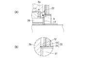
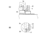
図4(A)は、気密空間20の気密保持のために設けられるシール溶接部の構造部分の一例を示している。図4(B)は、図4(A)の円形部分「b」をさらに拡大して示している。
FIG. 4A shows an example of a structure portion of a seal welded portion provided for airtight maintenance of the
これらの図4(A)、(B)に示すように、保持枠17の内周面側には、燃料キャスク保管時にキャスク本体2の周壁2aに設けたシール溶接用リップ11と互いに接する部位に対応して、保持枠側シール溶接用突起(リップ)21が設けられている。そして、これらシール溶接用リップ11,21同士が互いに溶接され、これによりシール溶接部22が形成されている。このシール溶接部22により、気密空間20の上隅部が気密にシールされ、気密空間20の密封が確実になされるようになっている。
As shown in FIGS. 4 (A) and 4 (B), on the inner peripheral surface side of the holding
なお、図1に示したように、このシール溶接部22を覆うように密閉カバー23を設け、シール部の健全性を確認できるようにすることが望ましい。
In addition, as shown in FIG. 1, it is desirable to provide the
図5(A)は、気密空間20の気密保持のために設けられるシール溶接部の構造部分の他の例を示している。図5(B)は、図5(A)の円形部分「b」をさらに拡大して示している。
FIG. 5 (A) shows another example of the structural portion of the seal welded portion that is provided to keep the
これらの図5(A)、(B)に示す例では、キャスク本体2のシール溶接用リップ11が、周壁2aの開口部側の端面に形成されている。そして、保持枠17の内周面側には、このキャスク本体2のシール溶接用リップ11と燃料キャスク保管時に互いに接する部位に対応して、保持枠側シール溶接用突起(リップ)21が設けられている。このような構成によって、シール溶接用リップ11,21同士が互いに溶接され、これによりシール溶接部22が形成される。
In the examples shown in FIGS. 5A and 5B, the
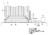
以上の構成において、本実施形態では、さらに図6に示すように、気密空間20に接続されるサンプリング装置23が設けられている。すなわち、保持枠17を貫通して気密空間の内外を連通するサンプリング配管24が設けられ、このサンプリング配管24に、気密空間内の圧力、温度、気体の種類、および放射性物質の1以上を検出するサンプリング装置が接続されている。具体的には、気密空間20に、これを漏えい検出空間として貯蔵架台14の任意の位置、例えば保持枠17の円筒状の胴部に漏えい検知を行うための架台側サンプリング配管24(24a)が付設され、着脱可能な接続バルブ25およびサンプリング装置側サンプリング配管24(24b)を介してサンプリング装置23が接続されている。
In the above configuration, in the present embodiment, a
このサンプリング装置23は、漏えい検知空間である気密空間20内のガスを吸引して、漏えいを検出できるように、真空ポンプなどの吸引装置を備えている。そして、ガス中に放出された放射性物質の検出を行うことができる計測器類、圧力の検出装置、キャスク本体内部に充填されているヘリウムガス等の不活性ガスを検出するリーク検出器、温度計測器等を搭載している。そして、キャスク本体2と二次蓋6bとで形成する密封境界からの放射性物質の漏えいを、多方面から検出することができるようになっている。勿論、必要に応じ、計測器類を増減することが可能である。
The
サンプリング装置23は、密封を保ちながら、架台側サンプリング配管24aに接続できればよい。なお、固定配管を介して常時接続して置くこと、例示のように着脱可能として置くこと、あるいは、着脱可能な接続バルブを介して常時接続すること等が可能である。
The
また、多数の燃料キャスク1の貯蔵に当たっては、一つのサンプリング装置23に各々の気密空間20からの配管を順次つなぎ代えて漏えい検出を行うことも可能である。
In storing a large number of
なお、サンプリング装置23には、各々の気密空間20に近接することができるように、車輪を設け、可般式とすることが望ましい。
Note that it is desirable that the
さらに、サンプリング装置23は、検出データの定期的な取込み機能、または異常検出時に警報を出力する機能を備えている。
Further, the
次に、本実施形態の燃料キャスク保管方法について説明する。 Next, the fuel cask storage method of this embodiment will be described.
まず、燃料キャスク1の蓋側である上端側を下に向けた状態で、貯蔵架台14に装着し、トラニオン9を貯蔵架台14のキャスク支持部に搭載して固定し、倒立保持状態とする。
First, with the upper end side, which is the lid side of the
次に、キャスク本体2と貯蔵架台14とで形成される狭い隙間に形成されたシール溶接用リップ11,21の先端をシール溶接することにより、キャスク本体2と二次蓋6bと貯蔵架台14とで漏えい検出用の気密空間20を形成する。
Next, the ends of the
この気密空間20に架台側サンプリング配管24aと着脱可能な接続バルブ25およびサンプリング装置側サンプリング配管24bを介してサンプリング装置23を接続し、この気密空間20内には、キャスク本体2内部に充填された不活性ガス以外の不活性ガスを充填する。気密空間20内は、真空もしくは空気としておくことも可能であり、いずれにしても密封を保ちながら、蓋用金属シールからの微量の放射性物質を含むガスの漏えいを検知できることを条件とする。
A
以上のように、本実施形態では、燃料キャスク1を、保管場所の床上に固定配置される基台16に固定保持する燃料キャスク保管方法であって、下向きとなったキャスク本体2の二次蓋6bの下面側に気密空間20を形成し、この気密空間20内の圧力、温度、気体の種類、および放射性物質の1以上を検出しつつ、燃料キャスク1を保管するものである。
As described above, in this embodiment, the
なお、密封空間20の圧力および漏洩放射性物質検知結果を常時監視するシステムを具備し、異常があった場合には、警報を発するとともに、データを定期的に保存用計算機に取込み異常の診断および予防に役立てることが望ましい。
In addition, a system that constantly monitors the pressure in the sealed
また、本発明においては、ガスサンプリングシステムを、貯蔵架台14と別置きのユニットとすることが望ましい。
In the present invention, it is desirable that the gas sampling system is a unit separately from the
本実施形態によれば、漏えい検出システムを用いることにより、保管中のキャスクのキャスク本体2と一次蓋6aおよび二次蓋6bにより形成される密封境界部からのキャスク保管期間中の放射性物質を含む充填ガスの漏えいを、確実に検出することができるとともに、放射性物質の漏えいの拡大を防止することができる。
According to the present embodiment, the leak detection system is used to include radioactive materials during the cask storage period from the sealed boundary formed by the
また、このような漏えい検出方法を用いれば、これまで密封境界の健全性を確認するために一次蓋6aと二次蓋6bとで形成する蓋間空間の圧力を監視するために、この空間まで二次蓋6bを穿孔し、二次蓋6bに圧力変動の検出装置を取付けていたものを、特別に設置する必要が無くなり、漏えい可能ルートの減少による信頼性の向上を図ることができる。
Moreover, if such a leak detection method is used, in order to monitor the pressure in the space between the lids formed by the
また、漏えいの可能性のある蓋部を全て密封空間内に収納するため、実際に漏えいが発生した際に、そのまま空間に放射性物質が流れ出ることが無く、安全性を向上できる。 In addition, since all the lids that may leak are housed in the sealed space, when a leak actually occurs, radioactive material does not flow into the space as it is, and safety can be improved.
さらに、サンプリング装置23を順次つなぎ代えて漏えい検出を行うことが可能であり、キャスク各々に圧力検出装置を設ける従来の技術に対して経済性の向上が図れる。
Further, it is possible to perform leakage detection by sequentially connecting the
さらに加えて、サンプリング装置23は、放射性物質のみならず、圧力や温度等の多くの検出器を設置することが可能であり、漏えい検出の確率を、キャスク密封境界部を傷めることなく向上させることができる。
In addition, the
1 燃料キャスク
2 キャスク本体
2a 周壁
3 中性子遮蔽体
4 開口部
4a 第1段開口部
4b 第2段開口部
5 使用済燃料
6 蓋
6a 一次蓋
6b 二次蓋
7a,7b 蓋用金属シール
9 トラニオン
10 締結具
11 シール溶接用突起
12 窪み
13 保管装置
14 貯蔵架台
15 保管場所の床
16 基台
17 保持枠
18 固定部
19 キャスク支持部
20 気密空間
21 保持枠側シール溶接用突起(リップ)
22 シール溶接部
23 サンプリング装置
24 サンプリング配管
24b 架台側サンプリング装置側サンプリング配管
24b サンプリング装置側サンプリング配管
25 接続バルブ
26 車輪
DESCRIPTION OF
22
Claims (6)
Priority Applications (1)
| Application Number | Priority Date | Filing Date | Title |
|---|---|---|---|
| JP2004108312A JP2005291960A (en) | 2004-03-31 | 2004-03-31 | Fuel cask storage device and storage method |
Applications Claiming Priority (1)
| Application Number | Priority Date | Filing Date | Title |
|---|---|---|---|
| JP2004108312A JP2005291960A (en) | 2004-03-31 | 2004-03-31 | Fuel cask storage device and storage method |
Publications (1)
| Publication Number | Publication Date |
|---|---|
| JP2005291960A true JP2005291960A (en) | 2005-10-20 |
Family
ID=35325044
Family Applications (1)
| Application Number | Title | Priority Date | Filing Date |
|---|---|---|---|
| JP2004108312A Pending JP2005291960A (en) | 2004-03-31 | 2004-03-31 | Fuel cask storage device and storage method |
Country Status (1)
| Country | Link |
|---|---|
| JP (1) | JP2005291960A (en) |
Cited By (7)
| Publication number | Priority date | Publication date | Assignee | Title |
|---|---|---|---|---|
| JP2008089487A (en) * | 2006-10-04 | 2008-04-17 | Toshiba Corp | Radioactive material storage container and repair method thereof |
| JP2008298588A (en) * | 2007-05-31 | 2008-12-11 | Toyo Eng Corp | Fixed mount for radioactive material transport and storage containers |
| JP2015031523A (en) * | 2013-07-31 | 2015-02-16 | 一般財団法人電力中央研究所 | Concrete cask heat removal device and concrete cask |
| JP2015031524A (en) * | 2013-07-31 | 2015-02-16 | 一般財団法人電力中央研究所 | Gas sampling heat removal device for concrete cask and concrete cask |
| JP2020126001A (en) * | 2019-02-05 | 2020-08-20 | 株式会社千代田テクノル | Ground-based septic tank |
| CN112241019A (en) * | 2020-12-17 | 2021-01-19 | 上海电气核电集团有限公司 | Radioactive feed liquid sampling box and manufacturing process thereof |
| ES2923107R1 (en) * | 2022-07-08 | 2022-10-11 | Ingecid Investig Y Desarrollo De Proyectos S L | RADIOACTIVE GAS CONTAINMENT SYSTEM FOR NUCLEAR WASTE CONTAINERS |
-
2004
- 2004-03-31 JP JP2004108312A patent/JP2005291960A/en active Pending
Cited By (9)
| Publication number | Priority date | Publication date | Assignee | Title |
|---|---|---|---|---|
| JP2008089487A (en) * | 2006-10-04 | 2008-04-17 | Toshiba Corp | Radioactive material storage container and repair method thereof |
| JP2008298588A (en) * | 2007-05-31 | 2008-12-11 | Toyo Eng Corp | Fixed mount for radioactive material transport and storage containers |
| JP2015031523A (en) * | 2013-07-31 | 2015-02-16 | 一般財団法人電力中央研究所 | Concrete cask heat removal device and concrete cask |
| JP2015031524A (en) * | 2013-07-31 | 2015-02-16 | 一般財団法人電力中央研究所 | Gas sampling heat removal device for concrete cask and concrete cask |
| JP2020126001A (en) * | 2019-02-05 | 2020-08-20 | 株式会社千代田テクノル | Ground-based septic tank |
| JP7260109B2 (en) | 2019-02-05 | 2023-04-18 | 株式会社千代田テクノル | Ground type septic tank |
| CN112241019A (en) * | 2020-12-17 | 2021-01-19 | 上海电气核电集团有限公司 | Radioactive feed liquid sampling box and manufacturing process thereof |
| ES2923107R1 (en) * | 2022-07-08 | 2022-10-11 | Ingecid Investig Y Desarrollo De Proyectos S L | RADIOACTIVE GAS CONTAINMENT SYSTEM FOR NUCLEAR WASTE CONTAINERS |
| WO2024008989A1 (en) * | 2022-07-08 | 2024-01-11 | Ingecid, S.L. | Radioactive gas containment system for nuclear waste containers |
Similar Documents
| Publication | Publication Date | Title |
|---|---|---|
| KR102593423B1 (en) | Containment cask for drums containing radioactive hazardous waste | |
| KR100704214B1 (en) | Transportation and storage systems and methods for monitoring ultrapure product storage tanks during transportation | |
| US4278892A (en) | Radioactivity-shielding transport or storage receptacle for radioactive wastes | |
| JPS632080B2 (en) | ||
| WO2014036561A2 (en) | System and method for storing and leak testing a radioactive materials storage canister | |
| US3444725A (en) | Leak detecting and locating system for nuclear reactor containment vessels | |
| JP2003014889A (en) | Transportation cask for radioactive material and installation method for sealed vessel | |
| JP2005291960A (en) | Fuel cask storage device and storage method | |
| JPH10339797A (en) | Casing for transporting package of hazardous material | |
| US5269172A (en) | Processes and apparatus for the prevention, detection and/or repair of leaks or avenues for leaks from above-ground storage tanks | |
| JP2020128902A (en) | Radioactive waste storage device, monitoring device, and radioactive waste management method | |
| JP4404472B2 (en) | Leak detection method and leak detection device for sealed container | |
| JP6817164B2 (en) | Storage container for radioactive materials | |
| CN110185917A (en) | A kind of thin oil sealing gas cabinet | |
| JP2004226385A (en) | Canister abnormality detection system | |
| JP2003139887A (en) | Canister | |
| JP2000258595A (en) | Double lid monitoring device for canister | |
| US4495137A (en) | Nuclear reactor | |
| JPH0155440B2 (en) | ||
| JPH11287893A (en) | Lid structure of transportation/storage cask | |
| CN218840474U (en) | Novel connect liquid stand to pass through entirely device | |
| RU2221291C1 (en) | Shielding container for transport and/or storage of spent nuclear fuel | |
| US6823034B1 (en) | Closure mechanism and method for spent nuclear fuel canisters | |
| KR102858239B1 (en) | Ammonia ISO tank integrated control method and system for this | |
| JP2001242294A (en) | Method and apparatus for storing spent fuel |