JP2005291947A - Fine particle transfer device - Google Patents

Fine particle transfer device Download PDF

Info

Publication number
JP2005291947A
JP2005291947A JP2004108057A JP2004108057A JP2005291947A JP 2005291947 A JP2005291947 A JP 2005291947A JP 2004108057 A JP2004108057 A JP 2004108057A JP 2004108057 A JP2004108057 A JP 2004108057A JP 2005291947 A JP2005291947 A JP 2005291947A
Authority
JP
Japan
Prior art keywords
fine particle
flow path
path
particle transfer
transfer
Prior art date
Legal status (The legal status is an assumption and is not a legal conclusion. Google has not performed a legal analysis and makes no representation as to the accuracy of the status listed.)
Withdrawn
Application number
JP2004108057A
Other languages
Japanese (ja)
Inventor
Toyomi Miyagawa
豊美 宮川
Hajime Sudo
肇 須藤
Current Assignee (The listed assignees may be inaccurate. Google has not performed a legal analysis and makes no representation or warranty as to the accuracy of the list.)
Toshiba Corp
Original Assignee
Toshiba Corp
Priority date (The priority date is an assumption and is not a legal conclusion. Google has not performed a legal analysis and makes no representation as to the accuracy of the date listed.)
Filing date
Publication date
Application filed by Toshiba Corp filed Critical Toshiba Corp
Priority to JP2004108057A priority Critical patent/JP2005291947A/en
Publication of JP2005291947A publication Critical patent/JP2005291947A/en
Withdrawn legal-status Critical Current

Links

Images

Landscapes

  • Sampling And Sample Adjustment (AREA)
  • Micromachines (AREA)
  • Physical Or Chemical Processes And Apparatus (AREA)

Abstract

【課題】 簡便な機構で効率よく微粒子を整列させることができる微粒子移送装置を提供する。
【解決手段】 微粒子移送装置には微粒子を含む懸濁液を送液するための微粒子移送路と、両端が微粒子移送路に開口された補助流路が設けられている。微粒子移送路と補助流路の内部には複数の移送媒体が設けられている。移送媒体は、微粒子移送装置に設けられた移送媒体駆動手段によって微粒子移送路と補助流路の内部を移動する。微粒子移送路に送液された懸濁液中の微粒子は、移動する移送媒体によって挟まれ、整列される。
【選択図】 図1
PROBLEM TO BE SOLVED: To provide a fine particle transfer device capable of efficiently aligning fine particles with a simple mechanism.
A fine particle transfer device is provided with a fine particle transfer path for feeding a suspension containing fine particles and an auxiliary flow path having both ends opened to the fine particle transfer path. A plurality of transfer media are provided inside the fine particle transfer path and the auxiliary flow path. The transfer medium moves in the fine particle transfer path and the auxiliary flow path by the transfer medium driving means provided in the fine particle transfer device. The fine particles in the suspension sent to the fine particle transfer path are sandwiched and aligned by the moving transfer medium.
[Selection] Figure 1

Description

本発明は,流体を介して搬送される微粒子を整列するための微粒子移送装置に関する。   The present invention relates to a particle transfer device for aligning particles transferred via a fluid.

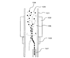
容器内の懸濁液中に含まれる、主に粒径50〜300μmの微粒子を捕獲、配列、させるために,放射圧(光,音)や静電場、磁場などの遠隔力を用いて非接触で微粒子を制御することが行われている。図7に従来の微粒子捕獲装置(非特許文献1)の部分拡大図を示す。   Non-contact using remote force such as radiation pressure (light, sound), electrostatic field, magnetic field, etc. to capture, arrange, and arrange fine particles with a particle size of 50-300μm contained in the suspension in the container. The fine particles are controlled by the above. FIG. 7 shows a partially enlarged view of a conventional fine particle capturing apparatus (Non-Patent Document 1).

容器101の内部では、第1の微粒子104と第2の微粒子105を含む懸濁液106がポンプ等で送液され、懸濁液106が流れている状態となっている。円筒状の容器101の外周には圧電振動子102、電極103が装着されている。   Inside the container 101, the suspension 106 containing the first fine particles 104 and the second fine particles 105 is fed by a pump or the like, and the suspension 106 is flowing. A piezoelectric vibrator 102 and an electrode 103 are mounted on the outer periphery of the cylindrical container 101.

圧着振動子102は外部より制御されることにより超音波を発生する。この超音波の位相、周波数を制御することで懸濁液106を撹拌し、非接触で第1の微粒子104と第2の微粒子105を回転、配列など操作する。さらに、電極103に電圧を加えて容器101の内部に電界を発生させて、配列された第1の微粒子104と第2の微粒子105を分離する。分離された第1の微粒子104と第2の微粒子105のうち第1の微粒子104のみを捕獲するように、容器101の内部に細管107を設ける。   The crimping vibrator 102 generates ultrasonic waves by being controlled from the outside. The suspension 106 is agitated by controlling the phase and frequency of this ultrasonic wave, and the first fine particles 104 and the second fine particles 105 are rotated, arranged, etc. in a non-contact manner. Further, a voltage is applied to the electrode 103 to generate an electric field inside the container 101, thereby separating the arranged first fine particles 104 and second fine particles 105. A narrow tube 107 is provided inside the container 101 so as to capture only the first fine particles 104 of the separated first fine particles 104 and second fine particles 105.

この様にして、従来の微粒子捕獲装置は懸濁液中の必要な微粒子のみを選択的に捕獲することができる。
マイクロマシン技術総覧((株)産業技術サービスセンター発行) 531項 図3.1
In this way, the conventional particle capturing apparatus can selectively capture only the necessary particles in the suspension.
Micromachine Technology Overview (issued by Industrial Technology Service Center Co., Ltd.) Section 531 Figure 3.1

ところが、従来の微粒子捕獲装置は、懸濁液から微粒子を選択的に捕獲するという点では優れているが、選択的に捕獲された微粒子を集合体でしか取り扱うことしかできず、微粒子を1個毎に整列させることはできないという問題点がある。   However, the conventional fine particle capturing apparatus is excellent in that the fine particles are selectively captured from the suspension. However, the selectively captured fine particles can only be handled as an aggregate, and one fine particle is handled. There is a problem that they cannot be aligned every time.

そこで、現在は微粒子を微粒子捕獲装置にて選択的に捕獲した後、マイクロピペット等で微粒子を1個づつ直接トラップ、移動、回転、固定等の操作(マイクロマニピュレーション)せざるをえない。このようなマイクロピペット等のマイクロマニピュレーションに用いる装置は大型で複雑なシステムである上、微粒子を1個づつ繰り返し操作し整列させるため、効率よく微粒子を整列させることができなかった。   Therefore, at present, after selectively capturing the microparticles with a microparticle capturing apparatus, the microparticles must be directly trapped, moved, rotated, fixed, etc. (micromanipulation) one by one. Such an apparatus used for micromanipulation such as a micropipette is a large and complicated system, and since the microparticles are repeatedly operated and aligned one by one, the microparticles cannot be efficiently aligned.

本発明は、このような事情を鑑みてされたもので、簡便な機構で効率よく微粒子を整列させることができる微粒子移送装置を提供することを目的とする。   The present invention has been made in view of such circumstances, and an object of the present invention is to provide a fine particle transfer device capable of efficiently aligning fine particles with a simple mechanism.

上記目的を達成するために、本発明の微粒子移送装置は、微粒子を含む懸濁液を送液するための微粒子移送路と、両端が前記微粒子移送路に開口された補助流路と、前記両端の間に位置する前記微粒子移送路の一部分、および前記補助流路の内部を移動する複数の移送媒体と、前記微粒子が前記微粒子移送路の一方の側から他方の側へ移送される際、前記微粒子を整列させるために、前記微粒子移送路内の隣接する前記移送媒体の間に1個の前記微粒子が位置するように、前記移送媒体を移動させるための移送媒体駆動手段と、前記一部分を除く前記微粒子移送路へ混入することを防止するための第1の混入防止手段と、前記微粒子が前記補助流路の内部へ混入することを防止するための第2の混入防止手段と、を有することを特徴とする。   In order to achieve the above object, the particulate transfer device of the present invention includes a particulate transport path for transporting a suspension containing particulates, an auxiliary channel having both ends opened in the particulate transport path, and the both ends. A part of the fine particle transfer path positioned between the plurality of transfer media moving inside the auxiliary flow path, and when the fine particles are transferred from one side of the fine particle transfer path to the other side, In order to align the fine particles, the transfer medium driving means for moving the transfer medium such that one of the fine particles is located between the adjacent transfer media in the fine particle transfer path, and excluding the part A first mixing preventing means for preventing the fine particles from being mixed into the fine particle transfer path; and a second mixing preventing means for preventing the fine particles from mixing into the auxiliary flow path. It is characterized by.

簡便な機構で効率よく微粒子を整列させることができる微粒子移送装置を提供することができる。   It is possible to provide a fine particle transfer device capable of efficiently aligning fine particles with a simple mechanism.

以下、本発明の実施の形態を図面を参照して説明する。   Hereinafter, embodiments of the present invention will be described with reference to the drawings.

(第1の実施の形態)
図1に本発明による微粒子移送装置の第1の実施の形態を示す。
(First embodiment)
FIG. 1 shows a first embodiment of a fine particle transfer apparatus according to the present invention.

微粒子移送装置1には、例えば図7に示す従来の微粒子移送装置等によって必要な微粒子のみを選択的が捕獲された懸濁液2を入れるための容器3が設けられている。なお、本実施の形態では説明の都合上、必要な微粒子は微粒子4のみの1種類である実施の形態について説明する。   The fine particle transfer device 1 is provided with a container 3 for containing a suspension 2 in which only necessary fine particles are selectively captured by, for example, the conventional fine particle transfer device shown in FIG. In this embodiment, for convenience of explanation, an embodiment in which the necessary fine particles are only one kind of fine particles 4 will be described.

微粒子移送装置1には、容器3に流路5にて接続された流路ブロック6が設けられている。流路ブロック6は、容器3から流路5を経て移送された微粒子4を1個毎に整列させる。   The particulate transfer device 1 is provided with a flow path block 6 connected to the container 3 by a flow path 5. The flow path block 6 aligns the fine particles 4 transferred from the container 3 through the flow path 5 one by one.

さらに、微粒子移送装置1には、流路ブロック6に流路7にて接続された整列収納部10が設けられている。整列収納部10は、流路ブロック6にて整列された微粒子4をトレー8に設けられたポケット9に、1ポケットにつき1個づつ収納する。   Further, the particulate transfer device 1 is provided with an alignment storage portion 10 connected to the flow path block 6 through the flow path 7. The alignment storage unit 10 stores the fine particles 4 aligned in the flow path block 6 one by one in the pocket 9 provided in the tray 8.

次に、流路ブロック6の詳細について説明する。   Next, details of the flow path block 6 will be described.

流路ブロック6の内部には、微粒子移送路11、微粒子移送路12、微粒子移送路13が設けられている。微粒子移送路11は流路5に接続され、微粒子移送路13は流路7に接続され、微粒子移送路12は、微粒子移送路11と微粒子移送路13の間に設けられている。よって容器3から流路5、微粒子移送路11、微粒子移送路12、微粒子移送路13、流路7を経て、整列収納部10まで連通した1本の流路が形成される。こうして、容器3に入れられた懸濁液2は、ポンプ等を有する送液手段20を用いて、容器3から整列収納部10への送液が可能となる。   Inside the flow path block 6, a fine particle transfer path 11, a fine particle transfer path 12, and a fine particle transfer path 13 are provided. The particulate transport path 11 is connected to the flow path 5, the particulate transport path 13 is connected to the flow path 7, and the particulate transport path 12 is provided between the particulate transport path 11 and the particulate transport path 13. Accordingly, a single flow path is formed which communicates from the container 3 to the alignment storage unit 10 through the flow path 5, the fine particle transfer path 11, the fine particle transfer path 12, the fine particle transfer path 13, and the flow path 7. Thus, the suspension 2 placed in the container 3 can be fed from the container 3 to the alignment storage unit 10 using the liquid feeding means 20 having a pump or the like.

流路ブロック6の内部には、微粒子移送路11と微粒子移送路12との接続部と、微粒子移送路12と微粒子移送路13との接続部近傍に開口された、補助流路14が設けられている。   Inside the flow path block 6, there are provided an auxiliary flow path 14 opened near the connection portion between the fine particle transfer path 11 and the fine particle transfer path 12 and the connection portion between the fine particle transfer path 12 and the fine particle transfer path 13. ing.

微粒子移送路12と補助流路14の内部には、プラスチック製磁石やフェライト磁石、鉄、ニッケル等の磁性体でできた移送媒体15が封入されている。移送媒体15は微粒子移送路12と補助流路14の内部をわずかな抵抗で移動できるように略球形の形状を有している。微粒子移送路11と微粒子移送路12との接続部と、微粒子移送路12と微粒子移送路13との接続部には、移送媒体15が微粒子移送路11と微粒子移送路13へ混入することを防止するための第1の混入防止手段が設けられている。   Inside the fine particle transfer path 12 and the auxiliary flow path 14, a transfer medium 15 made of a magnetic material such as a plastic magnet, a ferrite magnet, iron, or nickel is enclosed. The transfer medium 15 has a substantially spherical shape so that the inside of the fine particle transfer path 12 and the auxiliary flow path 14 can move with a slight resistance. The transfer medium 15 is prevented from being mixed into the fine particle transfer path 11 and the fine particle transfer path 13 at the connection portion between the fine particle transfer path 11 and the fine particle transfer path 12 and the connection portion between the fine particle transfer path 12 and the fine particle transfer path 13. A first mixing prevention means is provided for this purpose.

第1の混入防止手段の詳細について説明する。微粒子移送路11と微粒子移送路12との接続部には、移送媒体15が微粒子移送路11へ混入することを防止するための、狭窄部11a(第1の混入防止手段)が設けられている。同様に微粒子移送路13の微粒子移送路12と微粒子移送路13との接続部には、移送媒体15が微粒子移送路13へ混入することを防止するための、狭窄部13a(第1の混入防止手段)が設けられている。   Details of the first mixing prevention means will be described. A constriction portion 11a (first mixing prevention means) for preventing the transfer medium 15 from mixing into the fine particle transfer path 11 is provided at the connecting portion between the fine particle transfer path 11 and the fine particle transfer path 12. . Similarly, the constriction part 13a (first mixing prevention) for preventing the transfer medium 15 from entering the fine particle transfer path 13 is connected to the connecting part of the fine particle transfer path 13 between the fine particle transfer path 12 and the fine particle transfer path 13. Means).

具体的には、微粒子移送路12と補助流路14の断面方向の代表寸法(例えば断面形状が円形の場合は直径、正方形の場合は1辺の長さ)は移送媒体15の外形寸法より若干大きく設定する。すなわち、移送媒体15は微粒子移送路12と補助流路14の内部を移動できるが、移送媒体15が他の移送媒体15と微粒子移送路12と補助流路14の断面方向に2個ならぶことはできないようにする。一方、微粒子移送路11と微粒子移送路13の断面方向の代表寸法は、移送媒体15の外形寸法より小さく設定する。すなわち、移送媒体15は微粒子移送路12と補助流路14の内部を移動できるが、微粒子移送路11と微粒子移送路13には進入できないようにする。このように微粒子移送路11、微粒子移送路12、微粒子移送路13、補助流路14が一体的に形成された流路ブロック6は、封入された移送媒体15が微粒子移送路12と補助流路14の外へ出されることがないように構成されている。   Specifically, the representative dimensions in the cross-sectional direction of the fine particle transfer path 12 and the auxiliary flow path 14 (for example, the diameter when the cross-sectional shape is circular and the length of one side when the cross-sectional shape is square) are slightly larger than the external dimensions of the transfer medium 15. Set larger. That is, the transfer medium 15 can move inside the fine particle transfer path 12 and the auxiliary flow path 14, but two transfer media 15 are arranged in the cross-sectional direction of the other transfer medium 15, the fine particle transfer path 12, and the auxiliary flow path 14. I can't do it. On the other hand, the representative dimension in the cross-sectional direction of the fine particle transfer path 11 and the fine particle transfer path 13 is set smaller than the outer dimension of the transfer medium 15. That is, the transfer medium 15 can move in the fine particle transfer path 12 and the auxiliary flow path 14 but cannot enter the fine particle transfer path 11 and the fine particle transfer path 13. Thus, in the flow path block 6 in which the fine particle transfer path 11, the fine particle transfer path 12, the fine particle transfer path 13, and the auxiliary flow path 14 are integrally formed, the enclosed transfer medium 15 has the fine particle transfer path 12 and the auxiliary flow path. It is comprised so that it may not go out of 14.

微粒子移送路11と微粒子移送路12との接続部近傍と、微粒子移送路12と微粒子移送路13との接続部近傍の補助流路14には、混入防止手段16a(第2の混入防止手段)と混入防止手段16b(第2の混入防止手段)が設けられている。混入防止手段16aと混入防止手段16bは、微粒子4が補助流路14に混入することを防止するためのものである。   In the vicinity of the connection part between the fine particle transfer path 11 and the fine particle transfer path 12, and in the auxiliary flow path 14 in the vicinity of the connection part between the fine particle transfer path 12 and the fine particle transfer path 13, the mixing prevention means 16a (second mixing prevention means). And a mixing prevention means 16b (second mixing prevention means) are provided. The mixing prevention means 16a and the mixing prevention means 16b are for preventing the fine particles 4 from being mixed into the auxiliary flow path.

混入防止手段16aと混入防止手段16bの詳細について説明する。補助流路14には、微粒子移送路11と微粒子移送路12との接続部近傍と、微粒子移送路12と微粒子移送路13との接続部近傍に開口された、バルブ用流路17、バルブ用流路18が設けられている。バルブ用流路17とバルブ用流路18の一端は前述の通り接続部近傍に開口されているが、他端は行き止まりとなっている。   Details of the mixing prevention means 16a and the mixing prevention means 16b will be described. The auxiliary flow path 14 includes a valve flow path 17 and a valve opening that are opened in the vicinity of the connection between the fine particle transfer path 11 and the fine particle transfer path 12 and in the vicinity of the connection between the fine particle transfer path 12 and the fine particle transfer path 13. A flow path 18 is provided. One end of the valve flow path 17 and the valve flow path 18 is opened in the vicinity of the connecting portion as described above, but the other end is a dead end.

バルブ用流路17とバルブ用流路18の内部には、プラスチック製磁石やフェライト磁石、鉄、ニッケル等の磁性体でできたバルブ用媒体19が封入されている。バルブ用媒体19はバルブ用流路17およびバルブ用流路18の他端と、バルブ用流路17およびバルブ用流路の開口から補助流路14に出た部分との間をわずかな抵抗で移動できるように略球形の形状を有している。バルブ用媒体19は、バルブ用流路17およびバルブ用流路18の他端と、バルブ用流路17およびバルブ用流路18の開口から補助流路14に出た部分との間を移動することにより、補助流路14から微粒子移送路12へ、および微粒子移送路12から補助流路14へ移動する移送媒体15の進路を開放したり遮ったりすることができる。また、バルブ用媒体19は、バルブ用流路17およびバルブ用流路18の他端と、バルブ用流路17およびバルブ用流路の開口から補助流路14に出た部分との間を移動することにより、微粒子4が補助流路14に混入することを防止することができる。   A valve medium 19 made of a magnetic material such as a plastic magnet, a ferrite magnet, iron, or nickel is enclosed in the valve flow path 17 and the valve flow path 18. The valve medium 19 has a slight resistance between the other end of the valve flow path 17 and the valve flow path 18 and the portion of the valve flow path 17 and the valve flow path that opens to the auxiliary flow path 14. It has a substantially spherical shape so that it can move. The valve medium 19 moves between the other ends of the valve flow path 17 and the valve flow path 18 and a portion of the valve flow path 17 and the valve flow path 18 that protrudes from the opening to the auxiliary flow path 14. Thus, the path of the transfer medium 15 moving from the auxiliary flow path 14 to the fine particle transfer path 12 and from the fine particle transfer path 12 to the auxiliary flow path 14 can be opened or blocked. In addition, the valve medium 19 moves between the other ends of the valve flow path 17 and the valve flow path 18 and a portion of the valve flow path 17 and the valve flow path that are exposed to the auxiliary flow path 14. By doing so, it is possible to prevent the fine particles 4 from being mixed into the auxiliary flow path 14.

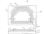
流路ブロック6には微粒子移送路11、微粒子移送路12、微粒子移送路13、補助流路14、バルブ用流路17、バルブ用流路18と略平行となる様に、図2に示す移送媒体駆動手段21が接続されている。移動媒体駆動手段21は、移送媒体15とバルブ用媒体19を非接触で移動させることができる。   In the flow path block 6, the transfer shown in FIG. 2 is arranged so as to be substantially parallel to the fine particle transfer path 11, the fine particle transfer path 12, the fine particle transfer path 13, the auxiliary flow path 14, the valve flow path 17, and the valve flow path 18. A medium driving means 21 is connected. The moving medium driving means 21 can move the transfer medium 15 and the valve medium 19 in a non-contact manner.

移動媒体駆動手段21の詳細について説明する。   Details of the moving medium driving means 21 will be described.

移動媒体駆動手段21には、例えば配線が施されたプリント配線板などの基板22が設けられている。基板22の一方の面には例えば着脱自在なコネクタなどの接続部23が設けられている。接続部23は、別途設けられた微粒子移送装置1を制御する例えばシーケンサなどの制御手段と微粒子移動装置1とを接続する。制御手段と微粒子移送装置1の接続には、例えばフラットケーブル等の接続配線(図示せず)を用いることができる。   The moving medium driving means 21 is provided with a substrate 22 such as a printed wiring board provided with wiring. A connection portion 23 such as a detachable connector is provided on one surface of the substrate 22. The connection unit 23 connects a control unit such as a sequencer for controlling the separately provided particle transfer device 1 to the particle moving device 1. For connection between the control means and the particle transfer device 1, for example, connection wiring (not shown) such as a flat cable can be used.

基板22の他方の面には、例えば空芯コイルや鉄心入りコイルなどの複数の磁力発生手段24(第1の磁力発生手段)が設けられている。磁力発生手段24は、例えば基板22に設けられた配線などを用いて接続部23に接続されている。磁力発生手段24は、微粒子移送路11、微粒子移送路12、微粒子移送路13、および補助流路14と略平行となる様に、図2に示すようにアレイ状に設けられている。また、磁力発生手段24は、磁力発生手段24の流路ブロック6側が、移動媒体15に対して吸引力を有する向きに設けられている。このように磁力発生手段24を設けることにより、任意の磁力発生手段24について磁力を発生させるように制御すると、この磁力発生手段24と移動媒体15の間に吸引力が生じ、移動媒体15を任意の方向へ非接触にて移動させることができる。この時、磁力発生手段24同士のピッチ25は、移送媒体15の大きさより小さくすると、理想的には移送媒体15の大きさの半分以下程度にすると、移送媒体15をより精度良く制御することができる。   The other surface of the substrate 22 is provided with a plurality of magnetic force generating means 24 (first magnetic force generating means) such as air core coils and iron core-containing coils. The magnetic force generation means 24 is connected to the connection portion 23 using, for example, wiring provided on the substrate 22. The magnetic force generating means 24 is provided in an array as shown in FIG. 2 so as to be substantially parallel to the fine particle transfer path 11, the fine particle transfer path 12, the fine particle transfer path 13, and the auxiliary flow path 14. Further, the magnetic force generating means 24 is provided in the direction in which the flow path block 6 side of the magnetic force generating means 24 has an attractive force with respect to the moving medium 15. By providing the magnetic force generating means 24 in this way, if the arbitrary magnetic force generating means 24 is controlled to generate a magnetic force, an attractive force is generated between the magnetic force generating means 24 and the moving medium 15, and the moving medium 15 is arbitrarily set. Can be moved in the non-contact direction. At this time, if the pitch 25 between the magnetic force generating means 24 is smaller than the size of the transfer medium 15, and ideally less than half the size of the transfer medium 15, the transfer medium 15 can be controlled more accurately. it can.

基板22の他方の面には、バルブ用媒体駆動手段である例えば空芯コイルや鉄心入りコイルなどの複数の磁力発生手段26(第2の磁力発生手段)が設けられている。磁力発生手段26は、例えば基板22に設けられた配線などを用いて接続部23に接続されている。磁力発生手段26は、補助流路14、バルブ用流路17、およびバルブ用流路18と略平行となる様に設けられている。また、図2に示すようにバルブ用媒体19がバルブ用流路17、バルブ用流路18の他端と、バルブ用流路17、バルブ用流路18の開口から補助流路14に出た部分との間を移動させることができる位置に、磁力発生手段26は設けられている。また、磁力発生手段26は、磁力発生手段26の流路ブロック6側が、バルブ用媒体19に対して吸引力を有する向きに設けられている。このように磁力発生手段26を設けることにより、任意の磁力発生手段26について磁力を発生させるように制御すると、この磁力発生手段26とバルブ用媒体19の間に吸引力が生じ、バルブ用媒体19を任意の方向へ非接触にて移動、保持させて、補助流路14をバルブ用媒体19で開閉することができる。   The other surface of the substrate 22 is provided with a plurality of magnetic force generating means 26 (second magnetic force generating means) such as air core coils and iron core-containing coils, which are valve medium driving means. The magnetic force generating means 26 is connected to the connecting portion 23 using, for example, wiring provided on the substrate 22. The magnetic force generating means 26 is provided so as to be substantially parallel to the auxiliary flow path 14, the valve flow path 17, and the valve flow path 18. Further, as shown in FIG. 2, the valve medium 19 exits to the auxiliary flow path 14 from the other end of the valve flow path 17 and the valve flow path 18 and the opening of the valve flow path 17 and the valve flow path 18. The magnetic force generating means 26 is provided at a position where it can be moved between the portions. Further, the magnetic force generating means 26 is provided on the flow path block 6 side of the magnetic force generating means 26 in a direction having an attractive force with respect to the valve medium 19. By providing the magnetic force generation means 26 in this way, if any magnetic force generation means 26 is controlled to generate a magnetic force, an attractive force is generated between the magnetic force generation means 26 and the valve medium 19, and the valve medium 19. The auxiliary flow path 14 can be opened and closed by the valve medium 19 by moving and holding in an arbitrary direction without contact.

図1に戻り、流路ブロック6の詳細についてさらに説明する。   Returning to FIG. 1, the details of the flow path block 6 will be further described.

流路ブロック6には、微粒子移送路11へ送液された懸濁液2に含まれる微粒子4をモニターするための画像センサー31が設けられている。また、流路ブロック6には、微粒子移送路12へ送液される懸濁液2に含まれる微粒子4の間隔を略一定に整列させるためのシャッター32が設けられている。シャッター32には微粒子4より小さい貫通孔が設けられているメッシュ状の板と、開閉手段(図示せず)が設けられている。シャッター32が閉じている時は、懸濁液2の液体部分のみが通過可能で、シャッター32が開いている時は、懸濁液2の液体部分と基に微粒子4が通過可能となる。シャッター32は画像センサー31によって取得される画像情報を元に、微粒子4が1個通過した後に閉じるように、そして微粒子4の間隔が略一定となるように間隔を空けた後開き、再び微粒子4が1個通過した後に再び閉じるように、と繰り返し開閉するように制御される。   The flow path block 6 is provided with an image sensor 31 for monitoring the fine particles 4 contained in the suspension 2 sent to the fine particle transfer path 11. Further, the flow path block 6 is provided with a shutter 32 for aligning the intervals of the fine particles 4 contained in the suspension 2 fed to the fine particle transfer path 12 substantially constant. The shutter 32 is provided with a mesh-like plate having through holes smaller than the fine particles 4 and an opening / closing means (not shown). When the shutter 32 is closed, only the liquid part of the suspension 2 can pass, and when the shutter 32 is opened, the fine particles 4 can pass based on the liquid part of the suspension 2. The shutter 32 opens based on the image information acquired by the image sensor 31 so that it closes after one particle 4 has passed, and opens after being spaced so that the interval between the particles 4 is substantially constant. It is controlled to open and close repeatedly so as to be closed again after one pass.

流路ブロック6の微粒子移送路12には、発光部と受光部を有する画像センサー33、試薬貯蔵部34、試薬供給部35、発光部と受光部を有する分光分析センサー36が設けられている。画像センサー33は、微粒子移送路12を2つの移送媒体15に挟まれて移送された微粒子4の初期の外観情報を取得することができる。試薬供給部35は、初期の外観情報を取得された微粒子4に対して、試薬貯蔵部34に貯蔵されている試薬を微粒子4に対して供給することができる。分光分析センサー36は試薬が供給された後の微粒子4の成分等の情報を取得することができる。   An image sensor 33 having a light emitting part and a light receiving part, a reagent storage part 34, a reagent supplying part 35, and a spectroscopic analysis sensor 36 having a light emitting part and a light receiving part are provided in the particle transport path 12 of the flow path block 6. The image sensor 33 can acquire the initial appearance information of the fine particles 4 transferred by sandwiching the fine particle transfer path 12 between the two transfer media 15. The reagent supply unit 35 can supply the reagent stored in the reagent storage unit 34 to the fine particles 4 for the fine particles 4 for which initial appearance information has been acquired. The spectroscopic sensor 36 can acquire information such as the components of the fine particles 4 after the reagent is supplied.

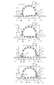
微粒子移送装置1の動作について図3に示す。   The operation of the particulate transfer device 1 is shown in FIG.

まず、図3(a)に示すように、バルブ用媒体19を補助流路14に出た部分へ移動し、保持させる。これにより、バルブ用媒体19によって移送媒体15は、補助流路14と微粒子移送路12との間を、行き来することができなくなる。   First, as shown in FIG. 3 (a), the valve medium 19 is moved to the portion of the auxiliary flow path 14 and held. As a result, the transfer medium 15 cannot travel between the auxiliary flow path 14 and the fine particle transfer path 12 by the valve medium 19.

次に、図3(b)に示すように、微粒子移送路12の中にある移送媒体15を、懸濁液2の流れる方向(本実施の形態では図中の→の方向)へ、移送媒体15の間隔を略同一に保ちながら、ほぼ同時に移動させる。この時、移送媒体15にて挟まれた微粒子4は、移送媒体15の動きに連動して懸濁液2の流れる方向へ移動し、図1に示すシャッター32の開閉によってシャッター32を通過した微粒子4が1個(微粒子4a)だけ、微粒子移送路11から微粒子移送路12へ移動する。   Next, as shown in FIG. 3B, the transfer medium 15 in the fine particle transfer path 12 is transferred in the direction in which the suspension 2 flows (in this embodiment, the direction of → in the figure). While keeping the interval of 15 substantially the same, the movement is performed almost simultaneously. At this time, the fine particles 4 sandwiched by the transfer medium 15 move in the direction in which the suspension 2 flows in conjunction with the movement of the transfer medium 15 and pass through the shutter 32 by opening and closing the shutter 32 shown in FIG. Only one 4 (fine particles 4 a) moves from the fine particle transfer path 11 to the fine particle transfer path 12.

そして、図3(c)に示すように、バルブ用媒体19を、補助流路14からバルブ用流路17およびバルブ用流路18の行き止まりとなっている他端へと移動し、保持させる。これにより、バルブ用媒体19によって移送媒体15は、補助流路14と微粒子移送路12との間を、行き来することができるようになる。バルブ用媒体19を移動、保持させた後、移送媒体15aと移送媒体15bが図3(b)に示す位置から図3(c)に示す位置まで移動するように、移送媒体15aと補助流路14の内部の移送媒体15を、移送媒体15の間隔を略同一に保ちながら、ほぼ同時に移動させる。この時、図3(b)にて微粒子移送路11から微粒子移送路12へ移動した微粒子4aは、移送媒体15bが補助流路14から微粒子移送路12へ移動することにより、移送媒体15にて挟まれた状態となる。   Then, as shown in FIG. 3C, the valve medium 19 is moved from the auxiliary flow path 14 to the other end where the valve flow path 17 and the valve flow path 18 are dead ends, and held. Thereby, the transfer medium 15 can go back and forth between the auxiliary flow path 14 and the fine particle transfer path 12 by the valve medium 19. After the valve medium 19 is moved and held, the transfer medium 15a and the auxiliary flow path are arranged so that the transfer medium 15a and the transfer medium 15b move from the position shown in FIG. 3B to the position shown in FIG. 3C. The transfer medium 15 inside 14 is moved substantially simultaneously while keeping the interval of the transfer medium 15 substantially the same. At this time, the fine particles 4 a moved from the fine particle transfer path 11 to the fine particle transfer path 12 in FIG. 3B are transferred to the fine particle transfer path 12 from the auxiliary flow path 14 by the transfer medium 15. It will be sandwiched.

図3(d)に示すように、再びバルブ用媒体19を補助流路14に出た部分へ移動し、保持させる。バルブ用媒体19を移動、保持させた後、微粒子移送路12の中にある移送媒体15を、懸濁液2の流れる方向(本実施の形態では図中の→の方向)へ、移送媒体15の間隔を略同一に保ちながら、ほぼ同時に移動させる。この時、移送媒体15にて挟まれた微粒子4は、移送媒体15の動きに連動して懸濁液2の流れる方向へ移動し、微粒子4が1個(微粒子4b)だけ、微粒子移送路12から微粒子移送路13へ移動する。同時に、図1に示すシャッター32の開閉によってシャッター32を通過した微粒子4が1個(微粒子4c)だけ、微粒子移送路11から微粒子移送路12へ移動する。これらの図3(a)から図3(d)の動作を繰り返す。   As shown in FIG. 3D, the valve medium 19 is moved again to the portion that has exited the auxiliary flow path 14 and is held. After the valve medium 19 is moved and held, the transfer medium 15 in the fine particle transfer path 12 is moved in the direction in which the suspension 2 flows (in this embodiment, the direction of → in the figure). The distance between the two is moved substantially at the same time while keeping the intervals substantially the same. At this time, the fine particles 4 sandwiched by the transfer medium 15 move in the direction in which the suspension 2 flows in conjunction with the movement of the transfer medium 15, and only one fine particle 4 (fine particles 4 b) is present in the fine particle transfer path 12. To the fine particle transfer path 13. At the same time, by the opening and closing of the shutter 32 shown in FIG. 1, only one particle 4 (particle 4c) that has passed through the shutter 32 moves from the particle transfer path 11 to the particle transfer path 12. These operations of FIG. 3A to FIG. 3D are repeated.

このように、第1の実施の形態による微粒子移送装置は、マイクロピペット等の大型で複雑なマイクロマニピュレーションシステムを用いることなく、簡便な機構で効率よく微粒子を整列させることができる。   As described above, the fine particle transfer apparatus according to the first embodiment can efficiently arrange the fine particles with a simple mechanism without using a large and complicated micromanipulation system such as a micropipette.

また、画像センサー33や試薬供給部35、分光分析センサー36を用いることで、例えば、画像センサー33にて傷のついた微粒子を判別し、試薬供給部35から微粒子に試薬を供給して反応させて、分光分析センサー36にて試薬に対する反応の度合いを判別した後、例えば傷のついた微粒子は不良品用のトレーへ、試薬に対し反応を示した微粒子は反応有り品のトレーへ、試薬に対して反応を示さなかった微粒子は反応無し品トレーへ、それぞれ収納することができる。このように、微粒子4の良品、不良品の判別やカテゴリー選別など任意の微粒子4を判別し、整理収納部10にて、良品のみの回収や、カテゴリー別にトレー8へ収納するなど、所望の微粒子4を所望の配列にて整列させることができる。   Further, by using the image sensor 33, the reagent supply unit 35, and the spectroscopic analysis sensor 36, for example, the image sensor 33 discriminates the damaged fine particles, and the reagent is supplied from the reagent supply unit 35 to the microparticles to be reacted. After the spectroscopic sensor 36 determines the degree of reaction to the reagent, for example, the damaged fine particles are transferred to the defective product tray, and the fine particles that have reacted to the reagent are transferred to the reacted product tray. On the other hand, the fine particles that have not reacted can be stored in the unreacted product tray. In this way, it is possible to discriminate arbitrary fine particles 4 such as non-defective / defective products of fine particles 4 and category selection, and to collect desired non-defective particles in the organizing and storing unit 10 or store them in the tray 8 by category. 4 can be aligned in the desired sequence.

(第2の実施の形態)
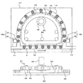
図4に本発明による微粒子移送装置の第2の実施の形態を示す。なお、第1の実施の形態と同一部分については、同一符号で示し、その説明を省略する。また、図4は流路ブロック41および移動媒体駆動手段47のみの表示とし、他の部分については第1の実施の形態と同一のため図示を省略する。さらに、画像センサー31、シャッター32、画像センサー33、試薬貯蔵部34、試薬供給部35、分光分析センサー36についても、第1の実施の形態と同一のため、図示を省略する。
(Second Embodiment)
FIG. 4 shows a second embodiment of the fine particle transfer apparatus according to the present invention. Note that the same parts as those of the first embodiment are denoted by the same reference numerals, and the description thereof is omitted. FIG. 4 shows only the flow path block 41 and the moving medium driving means 47, and the other parts are the same as those in the first embodiment, and are not shown. Further, the image sensor 31, the shutter 32, the image sensor 33, the reagent storage unit 34, the reagent supply unit 35, and the spectroscopic analysis sensor 36 are also the same as those in the first embodiment, and are not shown.

流路ブロック41には微粒子移送路12および補助流路14に沿って移動するように、移送媒体駆動手段47が設けられている。   The flow path block 41 is provided with a transfer medium driving means 47 so as to move along the fine particle transfer path 12 and the auxiliary flow path 14.

移送媒体駆動手段47には、微粒子移送路12と補助流路14にて形成される環状の流路の内周部に沿って移動するように、例えばゴム磁石など磁化された材料からなるベルト42(環状部材)が設けられている。ベルト42には例えばビニールコーティングされた磁性体などからなる歯43(凸部)が設けられている。   The transfer medium driving means 47 includes a belt 42 made of a magnetized material such as a rubber magnet so as to move along the inner periphery of the annular flow path formed by the fine particle transfer path 12 and the auxiliary flow path 14. (Annular member) is provided. The belt 42 is provided with teeth 43 (convex portions) made of, for example, a magnetic material coated with vinyl.

ベルト42は微粒子移送路12および補助流路14に沿って移動可能にするための、ガイド44およびプーリー45が設けられている。プーリー45にはベルト42を移動させるためのモーター46(環状部材駆動手段)が設けられている。   The belt 42 is provided with a guide 44 and a pulley 45 for enabling movement along the fine particle transfer path 12 and the auxiliary flow path 14. The pulley 45 is provided with a motor 46 (annular member driving means) for moving the belt 42.

移送媒体15は、ベルト42と歯43の磁力に吸引され、モーター46の回転に伴い、微粒子移送路12と補助流路14からなる環状の流路を移動する。また、磁力発生手段26は、バルブ用媒体19を移動させることができるだけでなく、微粒子移送路11と微粒子移送路12との接続部近傍と、微粒子移送路12と微粒子移送路13との接続部近傍に位置する移送媒体15を、その発生する磁力によって移動させることができる。   The transfer medium 15 is attracted by the magnetic force of the belt 42 and the teeth 43, and moves in an annular flow path composed of the fine particle transfer path 12 and the auxiliary flow path 14 as the motor 46 rotates. The magnetic force generating means 26 can not only move the valve medium 19 but also the vicinity of the connecting portion between the fine particle transfer path 11 and the fine particle transfer path 12 and the connecting portion between the fine particle transfer path 12 and the fine particle transfer path 13. The transfer medium 15 located in the vicinity can be moved by the generated magnetic force.

このように、第2の実施の形態による微粒子移送装置は、第1の実施の形態による微粒子移送装置と同様に、マイクロピペット等の大型で複雑なマイクロマニピュレーションシステムを用いることなく、簡便な機構で効率よく微粒子を整列させることができる。   As described above, the particle transfer device according to the second embodiment has a simple mechanism without using a large and complicated micromanipulation system such as a micropipette, like the particle transfer device according to the first embodiment. Fine particles can be efficiently aligned.

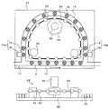
なお、流路ブロック41、移送媒体駆動手段47にかえて、図5に示すような流路ブロック51、移送媒体駆動手段52を用いても構わない。   Instead of the flow path block 41 and the transfer medium driving means 47, a flow path block 51 and a transfer medium driving means 52 as shown in FIG. 5 may be used.

流路ブロック51には、微粒子移送路12および補助流路14に沿って移動するように、移送媒体駆動手段52が設けられている。   The flow path block 51 is provided with a transfer medium driving means 52 so as to move along the fine particle transfer path 12 and the auxiliary flow path 14.

移送媒体駆動手段52には、微粒子移送路12と補助流路14にて形成される環状の流路の内周部に沿って移動するように、例えばゴム等からなるベルト53(環状部材)が設けられている。ベルト53には例えばフェライト磁石などからなる磁石54が設けられている。   The transfer medium driving means 52 has a belt 53 (annular member) made of, for example, rubber so as to move along the inner peripheral portion of the annular flow path formed by the fine particle transfer path 12 and the auxiliary flow path 14. Is provided. The belt 53 is provided with a magnet 54 made of, for example, a ferrite magnet.

ベルト53は微粒子移送路12および補助流路14に沿って移動可能にするための、ガイド44およびプーリー45が設けられている。プーリー45にはベルト53を移動させるためのモーター46(環状部材駆動手段)が設けられている。   The belt 53 is provided with a guide 44 and a pulley 45 for enabling movement along the fine particle transfer path 12 and the auxiliary flow path 14. The pulley 45 is provided with a motor 46 (annular member driving means) for moving the belt 53.

移送媒体15は、磁石54の磁力に吸引され、モーター46の回転に伴い、微粒子移送路12と補助流路14からなる環状の流路を移動する。また、磁力発生手段26は、バルブ用媒体19を移動させることができるだけでなく、微粒子移送路11と微粒子移送路12との接続部近傍と、微粒子移送路12と微粒子移送路13との接続部近傍に位置する移送媒体15を、その発生する磁力によって移動させることができる。   The transfer medium 15 is attracted by the magnetic force of the magnet 54, and moves in an annular flow path composed of the fine particle transfer path 12 and the auxiliary flow path 14 as the motor 46 rotates. The magnetic force generating means 26 can not only move the valve medium 19 but also the vicinity of the connecting portion between the fine particle transfer path 11 and the fine particle transfer path 12 and the connecting portion between the fine particle transfer path 12 and the fine particle transfer path 13. The transfer medium 15 located in the vicinity can be moved by the generated magnetic force.

このように、図5に示す第2の実施の形態による微粒子移送装置の変形例は、第2の実施の形態による微粒子移送装置と同様に、マイクロピペット等の大型で複雑なマイクロマニピュレーションシステムを用いることなく、簡便な機構で効率よく微粒子を整列させることができる。   As described above, the modified example of the particle transfer device according to the second embodiment shown in FIG. 5 uses a large and complicated micromanipulation system such as a micropipette, as in the particle transfer device according to the second embodiment. Therefore, the fine particles can be efficiently aligned by a simple mechanism.

(第3の実施の形態)
図6に本発明による微粒子移送装置の第3の実施の形態を示す。なお、第1の実施の形態および第2の実施の形態と同一部分については、同一符号で示し、その説明を省略する。また、図6は流路ブロック61および移動媒体駆動手段62のみの表示とし、他の部分については第1の実施の形態と同一のため図示を省略する。さらに、画像センサー31、シャッター32、画像センサー33、試薬貯蔵部34、試薬供給部35、分光分析センサー36についても、第1の実施の形態と同一のため、図示を省略する。
(Third embodiment)
FIG. 6 shows a third embodiment of the fine particle transfer apparatus according to the present invention. Note that the same parts as those in the first embodiment and the second embodiment are denoted by the same reference numerals, and the description thereof is omitted. FIG. 6 shows only the flow path block 61 and the moving medium driving means 62, and the other parts are the same as those in the first embodiment, and are not shown. Further, the image sensor 31, the shutter 32, the image sensor 33, the reagent storage unit 34, the reagent supply unit 35, and the spectroscopic analysis sensor 36 are also the same as those in the first embodiment, and are not shown.

流路ブロック61には微粒子移送路12および補助流路14に沿って移動するように、移送媒体駆動手段62が設けられている。   The flow path block 61 is provided with a transfer medium driving means 62 so as to move along the fine particle transfer path 12 and the auxiliary flow path 14.

移送媒体駆動手段62には、微粒子移送路12と補助流路14にて形成される環状の流路の内周部に沿って移動するように、例えば樹脂材料の素線などからなるロープ63(環状部材)が設けられている。ロープ63には例えばビニールコーティングされたフェライト磁石などからなる磁石64が設けられている。   The transfer medium driving means 62 includes, for example, a rope 63 (for example, a strand of resin material so as to move along the inner periphery of the annular flow path formed by the fine particle transfer path 12 and the auxiliary flow path 14. An annular member) is provided. The rope 63 is provided with a magnet 64 made of, for example, a vinyl-coated ferrite magnet.

ロープ63は微粒子移送路12および補助流路14に沿って移動可能にするための、ガイド44および歯付プーリー65が設けられている。歯付プーリー65にはロープ63を移動させるためのモーター46(環状部材駆動手段)が設けられている。   The rope 63 is provided with a guide 44 and a toothed pulley 65 for enabling movement along the fine particle transfer path 12 and the auxiliary flow path 14. The toothed pulley 65 is provided with a motor 46 (annular member driving means) for moving the rope 63.

移送媒体15は、磁石64の磁力に吸引され、モーター46の回転に伴い、微粒子移送路12と補助流路14からなる環状の流路を移動する。また、磁力発生手段26は、バルブ用媒体19を移動させることができるだけでなく、微粒子移送路11と微粒子移送路12との接続部近傍と、微粒子移送路12と微粒子移送路13との接続部近傍に位置する移送媒体15を、その発生する磁力によって移動させることができる。   The transfer medium 15 is attracted by the magnetic force of the magnet 64, and moves in an annular flow path composed of the fine particle transfer path 12 and the auxiliary flow path 14 as the motor 46 rotates. The magnetic force generating means 26 can not only move the valve medium 19 but also the vicinity of the connecting portion between the fine particle transfer path 11 and the fine particle transfer path 12 and the connecting portion between the fine particle transfer path 12 and the fine particle transfer path 13. The transfer medium 15 located in the vicinity can be moved by the generated magnetic force.

このように、第3の実施の形態による微粒子移送装置は、第1の実施の形態による微粒子位相装置および第2の実施の形態による微粒子移送装置と同様に、マイクロピペット等の大型で複雑なマイクロマニピュレーションシステムを用いることなく、簡便な機構で効率よく微粒子を整列させることができる。   As described above, the particle transfer device according to the third embodiment is similar to the particle phase device according to the first embodiment and the particle transfer device according to the second embodiment. Fine particles can be efficiently aligned by a simple mechanism without using a manipulation system.

本発明による微粒子移送装置の第1の実施の形態を示す図。The figure which shows 1st Embodiment of the microparticles | fine-particles conveying apparatus by this invention. 本発明による微粒子移送装置の第1の実施の形態の移動媒体駆動手段を示す図。The figure which shows the moving medium drive means of 1st Embodiment of the microparticles | fine-particles conveying apparatus by this invention. 本発明による微粒子移送装置の第1の実施の形態の動作を示す図。The figure which shows operation | movement of 1st Embodiment of the microparticles | fine-particles conveying apparatus by this invention. 本発明による微粒子移送装置の第2の実施の形態を示す図。The figure which shows 2nd Embodiment of the microparticles | fine-particles conveying apparatus by this invention. 本発明による微粒子移送装置の第2の実施の形態の変形例を示す図。The figure which shows the modification of 2nd Embodiment of the fine particle transport apparatus by this invention. 本発明による微粒子移送装置の第3の実施の形態を示す図。The figure which shows 3rd Embodiment of the microparticles | fine-particles conveying apparatus by this invention. 従来の微粒子捕獲装置を示す図。The figure which shows the conventional fine particle capture apparatus.

符号の説明Explanation of symbols

1 微粒子移送装置
2 懸濁液
3 容器
4 微粒子
5、7 流路
6、41、51、61 流路ブロック
8 トレー
9 ポケット
10 整列収納部
11 微粒子移送路
11a、13a 狭窄部
12 微粒子移送路
13 微粒子移送路
14 補助流路
15 移送媒体
16a、16b 混入防止手段
17、18 バルブ用流路
19 バルブ用媒体
20 送液手段
21、47、52、62 移送媒体駆動手段
22 基板
23 接続部
24 磁力発生手段
25 ピッチ
26 磁力発生手段
31、33 画像センサー
32 シャッター
34 試薬貯蔵部
35 試薬供給部
36 分光分析センサー
42、53 ベルト
43 歯
44 ガイド
45 プーリー
46 モーター
54、64 磁石
63 ロープ
65 歯付プーリー
101 容器
102 圧電振動子
103 電極
104 第1の微粒子
105 第2の微粒子
106 懸濁液
107 細管
DESCRIPTION OF SYMBOLS 1 Fine particle transfer apparatus 2 Suspension 3 Container 4 Fine particle 5, 7 Flow path 6, 41, 51, 61 Flow path block 8 Tray 9 Pocket 10 Alignment storage part 11 Fine particle transfer path 11a, 13a Constriction part 12 Fine particle transfer path 13 Fine particle Transfer path 14 Auxiliary flow path 15 Transfer media 16a, 16b Mixing prevention means 17, 18 Valve flow path 19 Valve medium 20 Liquid supply means 21, 47, 52, 62 Transfer medium drive means 22 Substrate 23 Connection 24 Magnetic force generation means 25 Pitch 26 Magnetic force generating means 31, 33 Image sensor 32 Shutter 34 Reagent storage unit 35 Reagent supply unit 36 Spectroscopic sensor 42, 53 Belt 43 Tooth 44 Guide 45 Pulley 46 Motor 54, 64 Magnet 63 Rope 65 Toothed pulley 101 Container 102 Piezoelectric vibrator 103 Electrode 104 First fine particle 105 Second fine particle 106 Nigoeki 107 tubules

Claims (8)

微粒子を含む懸濁液を送液するための微粒子移送路と、
両端が前記微粒子移送路に開口された補助流路と、
前記両端の間に位置する前記微粒子移送路の一部分、および前記補助流路の内部を移動する複数の移送媒体と、
前記微粒子が前記微粒子移送路の一方の側から他方の側へ移送される際、前記微粒子を整列させるために、前記微粒子移送路内の隣接する前記移送媒体の間に1個の前記微粒子が位置するように、前記移送媒体を移動させるための移送媒体駆動手段と、
前記一部分を除く前記微粒子移送路へ混入することを防止するための第1の混入防止手段と、
前記微粒子が前記補助流路の内部へ混入することを防止するための第2の混入防止手段と、を有することを特徴とする微粒子移送装置。
A fine particle transfer path for feeding a suspension containing fine particles;
An auxiliary flow path having both ends opened to the fine particle transfer path;
A part of the fine particle transfer path located between the both ends, and a plurality of transfer media that move inside the auxiliary flow path;
When the fine particles are transferred from one side to the other side of the fine particle transfer path, one of the fine particles is positioned between adjacent transfer media in the fine particle transfer path to align the fine particles. A transfer medium driving means for moving the transfer medium;
First mixing preventing means for preventing mixing into the fine particle transport path excluding the part;
And a second mixing preventing means for preventing the fine particles from mixing into the auxiliary flow path.
前記移送媒体は、磁性体を有することを特徴とする請求項1に記載の微粒子移送装置。   The fine particle transfer device according to claim 1, wherein the transfer medium includes a magnetic material. 前記移送媒体駆動手段は、前記微粒子移送路および前記補助流路に略平行に並べられ、発生する磁力によって前記移送媒体を電磁吸引し、移動させるための第1の磁力発生手段を有することを特徴とする請求項2に記載の微粒子移送装置。   The transfer medium driving means includes first magnetic force generation means arranged in substantially parallel to the fine particle transfer path and the auxiliary flow path, for electromagnetically attracting and moving the transfer medium by generated magnetic force. The fine particle transfer apparatus according to claim 2. 前記移送媒体駆動手段は、磁化された環状部材と、
前記環状部材に設けられた磁性体を有する複数の凸部と、
前記凸部が前記微粒子移送路の前記両端の間の部分および前記補助流路に沿って移動するように、前記環状部材を回転させるための環状部材駆動手段と、
を有することを特徴とする請求項2に記載の微粒子移送装置。
The transfer medium driving means includes a magnetized annular member,
A plurality of convex portions having a magnetic body provided on the annular member;
An annular member driving means for rotating the annular member so that the convex portion moves along the portion between the both ends of the particulate transfer path and the auxiliary flow path;
The fine particle transfer device according to claim 2, comprising:
前記移送媒体駆動手段は、環状部材と、
前記環状部材に設けられた複数の磁石と、
前記磁石が前記微粒子移送路の前記両端の間の部分および前記補助流路に沿って移動するように、前記環状部材を回転させるための環状部材駆動手段と、
を有することを特徴とする請求項2に記載の微粒子移送装置。
The transfer medium driving means includes an annular member,
A plurality of magnets provided on the annular member;
An annular member driving means for rotating the annular member so that the magnet moves along the portion between the both ends of the particulate transfer path and the auxiliary flow path;
The fine particle transfer device according to claim 2, comprising:
前記第2の混入防止手段は、前記補助流路を開閉するための複数のバルブ用媒体と、
前記バルブ用媒体が前記補助流路を開閉するように移動させるためのバルブ用媒体駆動手段と、
を有することを特徴とする請求項1乃至請求項5のいずれか1項に記載の微粒子移送装置。
The second mixing preventing means includes a plurality of valve media for opening and closing the auxiliary flow path,
A valve medium driving means for moving the valve medium so as to open and close the auxiliary flow path;
The fine particle transfer device according to any one of claims 1 to 5, wherein
前記バルブ用媒体は、磁性体を有することを特徴とする請求項6に記載の微粒子移送装置。   The fine particle transfer device according to claim 6, wherein the valve medium includes a magnetic material. 前記バルブ用媒体駆動手段は、発生する磁力によって前記バルブ用媒体を電磁吸引し、前記補助流路を開閉するように移動させる複数の第2の磁力発生手段を有することを特徴とする請求項7に記載の微粒子移送装置。   8. The valve medium driving means includes a plurality of second magnetic force generation means for electromagnetically attracting the valve medium by a generated magnetic force and moving the auxiliary flow path to open and close. The fine particle transfer apparatus according to 1.
JP2004108057A 2004-03-31 2004-03-31 Fine particle transfer device Withdrawn JP2005291947A (en)

Priority Applications (1)

Application Number Priority Date Filing Date Title
JP2004108057A JP2005291947A (en) 2004-03-31 2004-03-31 Fine particle transfer device

Applications Claiming Priority (1)

Application Number Priority Date Filing Date Title
JP2004108057A JP2005291947A (en) 2004-03-31 2004-03-31 Fine particle transfer device

Publications (1)

Publication Number Publication Date
JP2005291947A true JP2005291947A (en) 2005-10-20

Family

ID=35325032

Family Applications (1)

Application Number Title Priority Date Filing Date
JP2004108057A Withdrawn JP2005291947A (en) 2004-03-31 2004-03-31 Fine particle transfer device

Country Status (1)

Country Link
JP (1) JP2005291947A (en)

Similar Documents

Publication Publication Date Title
JP5752042B2 (en) Magnetic reagent, magnetic reagent kit, magnetic carrier processing method and processing apparatus thereof
Wang Cargo-towing synthetic nanomachines: towards active transport in microchip devices
US20200057059A1 (en) Point-of-care diagnostic cartridge having a digital micro-fluidic testing substrate
US9744533B2 (en) Movement and selection of micro-objects in a microfluidic apparatus
JP6629237B2 (en) MEMS based particle isolation system
JP5396281B2 (en) Method for arranging microdevices, magnetic arrangement apparatus used in the method, microdevice product used in the method, and system for arranging microdevices
Martinez‐Pedrero et al. Assembly and transport of microscopic cargos via reconfigurable photoactivated magnetic microdockers
CN112512690A (en) Modular fluidic chip and fluid flow system including the same
WO2007109412B1 (en) Cantilevered coaxial flow injector apparatus and method for sorting particles
DE60201094D1 (en) Dosing device for a container
EP3842149A1 (en) Biological entity separation device
CN110872551A (en) Nucleic acid detection device and nucleic acid detection method
WO2009106282A2 (en) Acoustic levitation system
Ueltzhöffer et al. Magnetically patterned rolled-up exchange bias tubes: a paternoster for superparamagnetic beads
US9140714B2 (en) Bio-sensing device
JP2005291947A (en) Fine particle transfer device
US11571696B2 (en) Biological entity separation device and method of use
US10252268B2 (en) Automated driving of an assay
JP2020034496A (en) Method for processing sample, sample processor, program, and sample processing cartridge
Lucarini et al. Design of a novel magnetic platform for cell manipulation
JP2007101318A (en) Analysis equipment
US20180113126A1 (en) Automated Driving of an Assay
EP4528286A1 (en) Sample analyzer
EP1998092A3 (en) Electro-pneumatic valve, in particular servo valve of a pneumatic valve
US12523720B2 (en) Analyzing apparatus, magnetic field generating apparatus for analyzing apparatus, and analyzing method

Legal Events

Date Code Title Description
A761 Written withdrawal of application

Free format text: JAPANESE INTERMEDIATE CODE: A761

Effective date: 20060928