JP2005291913A - Pressure reduction test method and test apparatus of container - Google Patents
Pressure reduction test method and test apparatus of container Download PDFInfo
- Publication number
- JP2005291913A JP2005291913A JP2004107147A JP2004107147A JP2005291913A JP 2005291913 A JP2005291913 A JP 2005291913A JP 2004107147 A JP2004107147 A JP 2004107147A JP 2004107147 A JP2004107147 A JP 2004107147A JP 2005291913 A JP2005291913 A JP 2005291913A
- Authority
- JP
- Japan
- Prior art keywords
- pressure
- container
- measurement
- liquid
- test
- Prior art date
- Legal status (The legal status is an assumption and is not a legal conclusion. Google has not performed a legal analysis and makes no representation as to the accuracy of the status listed.)
- Granted
Links
- 238000012360 testing method Methods 0.000 title claims abstract description 99
- 238000010998 test method Methods 0.000 title claims abstract description 10
- 230000009467 reduction Effects 0.000 title claims abstract description 8
- 239000007788 liquid Substances 0.000 claims abstract description 121
- 238000005259 measurement Methods 0.000 claims description 99
- 238000009530 blood pressure measurement Methods 0.000 claims description 47
- 230000006837 decompression Effects 0.000 claims description 17
- 238000003860 storage Methods 0.000 claims description 15
- XLYOFNOQVPJJNP-UHFFFAOYSA-N water Substances O XLYOFNOQVPJJNP-UHFFFAOYSA-N 0.000 claims description 12
- 238000007599 discharging Methods 0.000 claims description 9
- 238000001514 detection method Methods 0.000 claims description 7
- 238000000034 method Methods 0.000 claims description 6
- 230000008569 process Effects 0.000 claims description 4
- 239000007789 gas Substances 0.000 abstract 1
- 238000002347 injection Methods 0.000 description 6
- 239000007924 injection Substances 0.000 description 6
- 230000008859 change Effects 0.000 description 3
- 238000000605 extraction Methods 0.000 description 3
- 230000007246 mechanism Effects 0.000 description 3
- 230000008878 coupling Effects 0.000 description 2
- 238000010168 coupling process Methods 0.000 description 2
- 238000005859 coupling reaction Methods 0.000 description 2
- 238000003825 pressing Methods 0.000 description 2
- 239000000243 solution Substances 0.000 description 2
- 235000011389 fruit/vegetable juice Nutrition 0.000 description 1
- 238000007689 inspection Methods 0.000 description 1
- 238000004519 manufacturing process Methods 0.000 description 1
- 238000012986 modification Methods 0.000 description 1
- 230000004048 modification Effects 0.000 description 1
- 238000012545 processing Methods 0.000 description 1
- 239000011347 resin Substances 0.000 description 1
- 229920005989 resin Polymers 0.000 description 1
Images

Landscapes
- Investigating Strength Of Materials By Application Of Mechanical Stress (AREA)
Abstract
Description
本発明は、ペットボトルなどの容器を減圧し、耐圧強度を測定する容器の減圧試験方法と試験装置に関する。 The present invention relates to a container decompression test method and a test apparatus for decompressing a container such as a PET bottle and measuring pressure resistance.
ペットボトルなどの容器は、内部に注入する液体から受ける圧力に対抗し得る所定の耐圧強度を有していなければならない。したがって、この容器の耐圧試験は、下記特許文献1に開示されているように、容器の内部に高圧を注入し、容器の耐圧強度を検査するものが一般的である。しかし、最近では、容器内部に高温の液体を入れた後、放置あるいは冷却することがある。このような場合には、一旦膨出した容器が減圧されることから、減圧試験を行なわなければならない。 Containers such as PET bottles must have a predetermined pressure resistance that can resist the pressure received from the liquid injected into the container. Therefore, the pressure resistance test of this container is generally performed by injecting a high pressure into the container and inspecting the pressure strength of the container, as disclosed in Patent Document 1 below. However, recently, after putting a high-temperature liquid into the container, it may be left or cooled. In such a case, since the container once swelled is decompressed, a decompression test must be performed.
しかし、減圧試験は、内部に高圧を注入する耐圧試験装置を単純に流用できるものではない。容器内部を減圧すると、液体内に溶け込んでいるガスあるいは空気が放出され、容器内部が圧力変動し、容器の強度を正確に測定できない虞がある。
本発明は、上記従来技術に伴う課題を解決し、液体内に溶け込んでいるガスあるいは空気の影響を受けることなく、計測液により満液状態とされたペットボトルなどの容器から液体を除去しつつ容器の形状変化と減圧圧力との関係を測定する、簡単でかつ迅速な容器の減圧試験方法と試験装置を提供することを目的とする。 The present invention solves the problems associated with the prior art described above, while removing liquid from a container such as a plastic bottle filled with a measurement liquid without being affected by gas or air dissolved in the liquid. It is an object of the present invention to provide a simple and rapid container depressurization test method and test apparatus for measuring a relationship between a change in shape of a container and a depressurization pressure.
上記目的を達成する本発明方法は、試験容器が気密に取付けられる密閉の圧力測定室に、計測液貯溜タンク内の計測液を定量ポンプにより供給し、満液状態とする計測液供給工程と、前記定量ポンプを作動し、前記圧力測定室内の計測液を吸引し排出することにより空気を除去する計測液排出工程と、前記定量ポンプを作動し、一定量の計測液を前記圧力測定室より排出し前記試験容器内を減圧し、前記圧力測定室の内圧を測定する測定工程と、からなり、前記試験容器の変形時点の内圧から当該試験容器の強度を測定することを特徴とする。 The method of the present invention for achieving the above object includes a measuring liquid supply step in which a measuring liquid in a measuring liquid storage tank is supplied to a sealed pressure measuring chamber to which a test vessel is hermetically attached by a metering pump, and the liquid is filled. Operates the metering pump to suck out the measuring liquid in the pressure measuring chamber and discharges it to remove air, and operates the metering pump to discharge a certain amount of measuring liquid from the pressure measuring chamber. And measuring the internal pressure of the pressure measuring chamber, and measuring the strength of the test container from the internal pressure at the time of deformation of the test container.
上記目的を達成する本発明装置は、試験容器が気密に取付けられる密閉の圧力測定室を有する容器取付け部と、当該圧力測定室にそれぞれ一端が連通され、他端が前記圧力測定室に対し計測液を定量供排する定量ポンプと連通され、前記圧力測定室に計測液を供給する供給回路および、前記圧力測定室から計測液を排出する排出回路と、前記定量ポンプと連通され、前記計測液が貯溜された計測液貯溜タンクと、前記圧力測定室の内圧を測定する圧力検知部材と、前記定量ポンプの作動、前記供給回路や排出回路の切換えを制御し、前記圧力検知部材からのデータが入力される制御部と、を有し、前記試験容器内から前記計測液を前記定量ポンプにより一定量排出することにより生じる負圧を測定し、前記試験容器の変形時点の内圧から当該試験容器の強度を測定することを特徴とする。 The apparatus of the present invention that achieves the above object includes a container mounting portion having a sealed pressure measurement chamber to which a test container is mounted in an airtight manner, one end communicating with the pressure measurement chamber, and the other end measuring with respect to the pressure measurement chamber. A measurement circuit that communicates with a metering pump that quantifies and discharges the liquid, supplies a measurement liquid to the pressure measurement chamber, a discharge circuit that discharges the measurement liquid from the pressure measurement chamber, and a metering pump that communicates with the measurement liquid Is used to control the measurement liquid storage tank, the pressure detection member for measuring the internal pressure of the pressure measurement chamber, the operation of the metering pump, the switching of the supply circuit and the discharge circuit, and the data from the pressure detection member An input control unit, measuring a negative pressure generated by discharging a predetermined amount of the measurement liquid from the test container by the metering pump, and measuring the internal pressure at the time of deformation of the test container. The strength of the test container and measuring.
本発明は、密閉の圧力測定室に気密に取付けた試験容器を計測液で満液状態とし、前記圧力測定室から計測液の一部を排出しつつ空気も除去した後、定量ポンプにより試験容器内から一定量の計測液を排出し試験容器内を減圧するので、溶け込みガスや空気の影響を受けることなく、定量ポンプの作動により容器の形状を変化させ、減圧による限界圧力が簡単に測定でき、試験容器の耐圧強度を簡単に知ることができる。また、計測液が満液状態から一部を排出し、空気を排除した状態で測定を開始するので、測定した内圧は精度のよいものとなる。 In the present invention, a test container that is airtightly attached to a sealed pressure measurement chamber is filled with a measurement liquid, and after removing part of the measurement liquid from the pressure measurement chamber and removing air, the test container is Since a certain amount of measurement liquid is discharged from the inside and the inside of the test vessel is depressurized, the shape of the vessel can be changed by operating the metering pump without being affected by dissolved gas or air, and the limit pressure due to depressurization can be measured easily. The pressure strength of the test container can be easily known. In addition, since the measurement liquid is partially discharged from the full liquid state and the measurement is started with the air excluded, the measured internal pressure becomes accurate.
前記測定工程において、圧力測定室を大気圧状態にして試験容器内の減圧を開始すると、測定開始点を正確に設定できる。 In the measurement step, when the pressure measurement chamber is brought to atmospheric pressure and pressure reduction in the test container is started, the measurement start point can be accurately set.
前記測定工程において、圧力測定室内を減圧し所定の待ち時間が経過した後かあるいは試験容器などの液面が安定した状態で、圧力測定室の内圧を測定すると、計測精度が一層向上することになる。 In the measurement step, if the internal pressure of the pressure measurement chamber is measured after the pressure measurement chamber is depressurized and a predetermined waiting time elapses or the liquid level of the test container is stable, the measurement accuracy is further improved. Become.
前記計測液として脱気水を使用すれば、溶け込みガスや空気の影響を排除した状態で、定量ポンプの作動により減圧圧力を簡単に精度よく測定できる。 If degassed water is used as the measurement liquid, the reduced pressure can be easily and accurately measured by operating the metering pump in a state where the influence of dissolved gas and air is eliminated.
本発明に係る容器の減圧試験装置は、試験容器の開口部を容器取付け部に装着し、定量ポンプで圧力測定室内に計測液を定量供排した後、圧力測定室の内圧を圧力検知部材で測定すると、制御部にデータが入力されるので、自動的に容器の減圧試験を精度よく簡単に行なうことができる。 The container depressurization test apparatus according to the present invention attaches the opening of the test container to the container mounting portion, and after quantifying and discharging the measurement liquid into the pressure measurement chamber with the metering pump, the internal pressure of the pressure measurement chamber is measured with the pressure detection member. When measurement is performed, data is input to the control unit, so that the container decompression test can be automatically and accurately performed.
前記試験容器内から計測液を排出することに伴って液面が昇降する液面計を設けると、圧力測定室を大気圧状態にして試験容器内の減圧を開始でき、測定開始点を正確に設定できる。 By providing a liquid level gauge that raises and lowers the liquid level as the measurement liquid is discharged from the test container, the pressure measurement chamber can be brought to atmospheric pressure, pressure reduction in the test container can be started, and the measurement start point can be accurately determined. Can be set.
前記圧力測定室の頂壁に空気溜りとなる凹部を設けると、空気抜きが極めて円滑にでき、空気の存在により測定の外乱要因を取り除くことができ、測定精度も向上する。 If a concave portion serving as an air reservoir is provided on the top wall of the pressure measurement chamber, air can be vented very smoothly, the cause of measurement disturbance can be removed due to the presence of air, and measurement accuracy can be improved.
以下、本発明の実施の形態を、図面を参照しつつ説明する。 Hereinafter, embodiments of the present invention will be described with reference to the drawings.
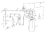
図1は本発明の実施の形態に係る容器の減圧試験装置の一例を示す概略図である。 FIG. 1 is a schematic view showing an example of a container decompression test apparatus according to an embodiment of the present invention.
例えば、ペットボトルに熱水などを入れた状態から放置あるいは冷却すると、ペットボトル内には負圧が作用し、収縮する。このような負圧に対しても所定の強度を有するか否かを試験する場合には、減圧試験を行なう。 For example, when the bottle is left or cooled after hot water or the like is put in the bottle, a negative pressure acts in the bottle and contracts. In order to test whether or not the negative pressure has a predetermined strength, a decompression test is performed.
図1に示す本実施形態の減圧試験装置について概説すれば、この減圧試験装置は、計測液Eが貯溜された計測液貯溜タンク1と、この計測液貯溜タンク1から計測液Eを取出す定量ポンプPと、試験容器2の開口部3が連通して装着される密閉の圧力測定室11を有する容器取付け部10と、圧力測定室11内の液面を測定する液面計20と、定量ポンプPからの計測液Eを圧力測定室11に供給する供給回路30と、圧力測定室11から計測液Eを排出する排出回路31と、定量ポンプPの作動を制御し、圧力測定室11に設けられた圧力検知部材12からのデータが入力される制御部Cと、を有している。
The decompression test apparatus according to the present embodiment shown in FIG. 1 is briefly described. The decompression test apparatus includes a measurement liquid storage tank 1 in which the measurement liquid E is stored, and a metering pump that takes out the measurement liquid E from the measurement liquid storage tank 1. P, a
さらに詳述する。計測液貯溜タンク1は、底部に排出用のコック2、頂部に蓋体3、側部に水位計4がそれぞれ設けられた大気開放型のタンクである。蓋体3を挿通して内部まで垂下された導管5は、内部の計測液Eを取出したり戻したりするもので、後述の定量ポンプPと連結されている。水位計4には下限センサ6が設けられ、最低限必要となる計測液Eを確保している。なお、導管5には、切換弁7および開閉弁8を介して計測液Eの使用量を測定する取出管9が連設されている。
Further details will be described. The measurement liquid storage tank 1 is an open-air tank having a
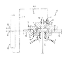
図2は同減圧試験装置の容器取付け部を示す断面図である。容器取付け部10は、図2に示すように、試験容器2の開口部3が連通するように気密に取付けられる圧力測定室11を有しているが、この圧力測定室11は、減圧試験装置が有している水平の基盤13を貫通して固定された分岐ブロック14と、分岐ブロック14の下部に螺合された容器取付け板15とにより区画形成されている。
FIG. 2 is a cross-sectional view showing a container mounting portion of the decompression test apparatus. As shown in FIG. 2, the
分岐ブロック14は、頂部に給排管16と、排気管17が設けられている。給排管16は、試験容器2の開口部3より内部まで垂下され、試験容器2内に計測液Eを供給したり排出したりするものである。排気管17は、その一端が分岐ブロック14に形成された排気通路18と連通され、他端が液面計20の下端と連通され、中間に第2電磁弁D2が設けられている。排気通路18は、圧力測定室11内の空気や計測液Eを、液面計20を介して計測液貯溜タンク1に排出するものであるが、本実施形態では、圧力測定室11内の頂壁11aに空気溜りとなる凹部11bが形成され、ここに排気通路18が連通されている。また、排気通路18には、圧力検知部材(圧力センサ)12の先端が臨まされ、圧力測定室11内の負圧圧力を感知し、圧力計Aで表示する一方、その負圧データが制御部Cに入力される。
The
容器取付け板15は、分岐ブロック14の下部に形成された環状凸部14aに螺合される環状凸部15aを有し、中央に試験容器2の口部4が螺合される取付穴19が開設されている。
The
液面計20は、試験容器2や圧力測定室11内に注入された計測液Eの液面を外部から検知するための透明な筒体であり、大気圧液面センサ21と、注入停止液面センサ22が設けられている。なお、液面計20の頂部は、オーバーフローした計測液Eを計測液貯溜タンク1に戻す導管23が連設されている。
The
供給回路30は、図1に示すように、導管32により第1電磁弁D1を介して合流部33と連通され、排出回路31は、導管34により逆止弁35および第3電磁弁D3を介して切換弁36と連通されている。したがって、これら第1電磁弁D1、切換弁36および第3電磁弁D3を制御すると、供給回路30と排出回路31に選択的に計測液Eを流すことができる。
As shown in FIG. 1, the
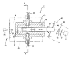
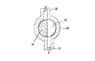
図3は定量ポンプを示す断面図、図4は図3の4−4線に沿う概略断面図である。図3に示すように、定量ポンプPは、ステッピングモータMによりカップリング40を介して回転されるピストン41を有している。なお。ステッピングモータMの軸線とピストン41の軸線とは交差しており、ユニバーサルジョイント(不図示)などにより円滑に回転伝達されるようになっている。
FIG. 3 is a sectional view showing the metering pump, and FIG. 4 is a schematic sectional view taken along line 4-4 of FIG. As shown in FIG. 3, the metering pump P has a
ピストン41は、先端部に凹欠部42が形成された柱状体であり、ケース43内に設けられたシリンダ44内で回転するが、シリンダ44内で軸方向にも往復動する。この往復動は、保持部材45に支持された斜板46により行なわれるが、ピストン41は、カップリング40の近傍に設けられた回転プレート47のスリット(不図示)を原点感知センサ48が感知するまでステッピングモータMが回転して軸方向に後退され、これが定量ポンプPの原点停止位置となる。
The
また、定量ポンプPは、吐出量を調整するストローク調整機構Tを有している。ストローク調整機構Tは、基盤13に対しスライド可能に設置されたスライド板49を有し、スライド板49上にケース43が設置され、スライド板49を指針50と目盛51を利用してスライドすることにより、シリンダ44内でのピストン41の位置を所望の位置に変化させ、定量ポンプPの吐出量を調整する。
The metering pump P has a stroke adjusting mechanism T that adjusts the discharge amount. The stroke adjustment mechanism T has a
シリンダ44およびケース43には、図1,3に示すように、切換弁36と連通された導管37と、切換弁7と連通された導管38がピストン41の軸線に対し直交するように設けられている。したがって、ステッピングモータMを正転あるいは逆転すると、定量ポンプPも同様に回転し、図4に示すように、導管37と導管38のいずれか一方(例えば、導管38)から流入した計測液Eがピストン41の凹欠部42から先端チャンバ52に流入し、同ピストン41の往復動により先端チャンバ52から他方(例えば、導管37)を通って一定量の計測液Eが吐出されることになる。
1 and 3, the
制御部Cは、演算処理部(コンピュータ)や制御機器などから構成され、圧力センサ12,大気圧液面センサ21,注入停止液面センサ22などから入力されたデータを記憶したり、また、第1電磁弁D1、第2電磁弁D2、第3電磁弁D3、定量ポンプPなどに制御信号を付与する。
The control unit C includes an arithmetic processing unit (computer), a control device, and the like, and stores data input from the
次に、試験容器の検査方法を説明する。 Next, a test container inspection method will be described.
<計測液供給工程>
試験容器2に注入する計測液Eは、実際の製品として注入されるジュースなどではなく、水が使用される。したがって、減圧時に空気やガスが発生することが少なく、測定も円滑に行なうことができる。より好ましくは、減圧時に空気やガスが発生することないもの、例えば、予め沸騰させて冷却した脱気水を使用することである。
<Measurement liquid supply process>
The measurement liquid E injected into the
まず、この計測液Eを計測液貯溜タンクに注入すると共に試験容器2にも注入する。試験容器2に注入するのは、試験容器2が大きい場合には、定量ポンプPを使用するより測定を迅速に行なうことができるからであるが、定量ポンプPを使用し注入してもよい。
First, the measurement liquid E is injected into the measurement liquid storage tank and also into the
ここで使用する計測液Eの温度は、圧力センサ12の基準値に合わせることが好ましいが、通常、圧力センサ12の基準値は25℃程度であるため、20℃±5℃が望ましい。
The temperature of the measuring liquid E used here is preferably matched with the reference value of the
試験容器2を容器取付け部10の容器取付け板15に装着した後、制御部Cの電源(不図示)を入れると、定量ポンプPのステッピングモータMが回転し、回転プレート47のスリットを原点感知センサ48が検知し、定量ポンプPが原点位置、つまり、ピストン41の最大後退位置で停止する。
After the
そして、制御部Cの注入ボタン(不図示)をONすると、定量ポンプPのステッピングモータMが回転し、ピストン41がシリンダ44内で往復動し、計測液貯溜タンク1内の計測液Eが試験容器2内に注入される。この注入時には、図1において、第1制御弁D1と第2制御弁D2が「開」状態、第3制御弁D3が「閉」状態となっているので、計測液Eは、計測液貯溜タンク1→定量ポンプP→第1制御弁D1→供給管16→試験容器2と流れ、試験容器2内に供給される。
When an injection button (not shown) of the control unit C is turned on, the stepping motor M of the metering pump P rotates, the
試験容器2内が満液状態となると、液面計20の注入停止液面センサ22がこれを検知し、制御部Cからの信号により定量ポンプPは停止する。
When the inside of the
<計測液排出工程と容器液面の大気液面合わせ>
しかし、測定開始は、常に一定の状態から行なうことが精度的にも作業的にも好ましいことから、大気圧液面センサ21が液面を感知するまで、定量ポンプPのステッピングモータを逆回転し、試験容器2内の計測液Eの一部を計測液貯溜タンク1に戻す。なお、制御部Cにおいて、定量ポンプPの作動は、試験容器2内の計測液Eを一定量(例えば、0.5cc)ずつ取り出した後、液面が安定するまで所定時間(例えば、3秒間)待って、再度回転を開始するように設定することもできる。このようにして、試験容器2内の液面を大気圧液面センサ21が感知するまで徐々に下げる。
<Measurement liquid discharge process and air level adjustment of container liquid level>
However, since it is preferable to always start the measurement from a constant state in terms of accuracy and work, the stepping motor of the metering pump P is reversely rotated until the atmospheric pressure
この結果、試験容器2内の液面と液面計20の液面とは、いわゆる大気液面となり、一致した液面となる。この結果、測定開始点を正確に設定できることになるが、さらに好ましいことに、試験容器2内から計測液Eの一部を排出することに伴って供給回路30や排出回路31内に存在する空気も一緒に外部に排出できることになり、回路が脱気され、測定精度が向上することにもなる。
As a result, the liquid level in the
両液面が一致すると、第1制御弁D1、第2制御弁D2、第3制御弁D3は「閉」状態となり、測定可能な状態となる。この段階では、試験容器2内の圧力は、1.0Kpaであるが、これら制御弁が閉じた後、再度試験容器2内の圧力が測定許容範囲にあるか否かを確認する。測定する日の気圧状態あるいは制御弁の閉鎖により圧力変動が生じる虞があるからである。
When the two liquid levels coincide, the first control valve D 1 , the second control valve D 2 , and the third control valve D 3 are in the “closed” state, and can be measured. At this stage, the pressure in the
<測定工程>
測定に当たっては、制御部Cに測定条件を入力する。例えば、計測待ち時間(1回の抽出後圧力が安定するまでの時間、例えば、3秒)、吸引量(1回目の抽出する量は、例えば、0cc、2回目は、5cc、3回目から5回目までは、1cc、以降は、0.5ccなど)、吸引回数(吸引回数は基本的には何回でもよい)などの条件を設定する。
<Measurement process>
In the measurement, measurement conditions are input to the control unit C. For example, measurement waiting time (time until pressure stabilizes after one extraction, for example, 3 seconds), suction amount (first extraction amount is, for example, 0 cc, second is 5 cc, third to 5 Conditions are set such as 1 cc until the first time, 0.5 cc thereafter, and the number of times of suction (the number of times of suction may be basically any number).
設定後、制御部Cの定量抽出ボタン(不図示)を押すと、第3制御弁D3のみが「開」状態となると共に、ステッピングモータMが作動する。 After setting, pressing quantitative extraction button of the control unit C (not shown), with only the third control valve D 3 is "open" state, the stepping motor M is operated.
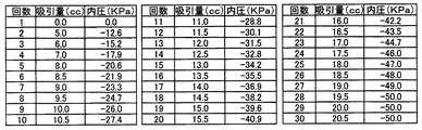
定量ポンプPが作動すると、計測液Eは、図5に示すように、1回目は、0CC吸引され、所定の計測待ち時間後、2回目は、5cc吸引され、所定の計測待ち時間後、3回目が吸引される。3回目から5回目までは、1ccずつの吸引と待ち時間が繰り返され、6回目以降は、0.5ccずつの吸引と待ち時間が繰り返される。 When the metering pump P is actuated, as shown in FIG. 5, the measurement liquid E is aspirated at 0 CC for the first time, after a predetermined measurement waiting time, and is sucked at 5 cc for the second time, and after a predetermined measurement waiting time, 3 The second time is aspirated. From the third time to the fifth time, suction and waiting time of 1 cc are repeated, and after the sixth time, suction and waiting time of 0.5 cc are repeated.
そして、待ち時間の間に試験容器2内の圧力が圧力センサ12により検知され、圧力計Aに表示され、制御部Cには負圧データとして取り込まれる。
During the waiting time, the pressure in the
ここにおいて、定量ポンプPの吸引量の変更は、ストローク調整機構Tの目盛51の位置を適宜調節することにより行なう。目盛位置を調節すれば、ステッピングモータM側の軸線に対するピストン41の軸線の傾き角度が変化し、ピストン41のストロークを調整でき、吸引量を変更できる。なお、ステッピングモータMが正逆可能であるため、吐出量も同様に変更することができることはいうまでもない。
Here, the suction amount of the metering pump P is changed by appropriately adjusting the position of the
<測定の完了>
試験容器2内から計測液Eが吸引されると、試験容器2内の圧力は次第に減圧されることになり、やがて試験容器2自体の形状が変化する。この変化を観察すると、測定は完了するが、数値的には、定量吸引しても試験容器2内の圧力値が変化しない定常状態となる。例えば、図5の25回目から30回目までの内圧値が示すように、複数回吸引しても試験容器2内の圧力は、殆ど−50Kpa程度となり、図6に示すように、圧力が−50Kpaで横軸と平行な状態となる。この状態になると測定は完了する。なお、吸引限界圧以上に減圧が進むと、試験容器2からは計測水を吸引することができなくなる場合もある。
<Completion of measurement>
When the measurement liquid E is sucked from the
<計測水の排出>
測定が完了すると、制御部Cの排出ボタン(不図示)をONすると、第1制御弁D1と第2制御弁D2が「閉」状態、第3制御弁D3が「開」状態となり、定量ポンプPのステッピングモータMが作動し、試験容器2内から計測水Eが計測液貯溜タンク1内に排出される。なお、この排出の途中で停止ボタン(不図示)を押し、排出を停止してもよい。排出を停止した後、容器取付け部10から試験容器2を外す。
<Discharge of measurement water>
When the measurement is completed, ON the eject button of the controller C (not shown), the first control valve D 1 and the second control valve D 2 is "closed" state, the third control valve D 3 becomes "open" state Then, the stepping motor M of the metering pump P is operated, and the measurement water E is discharged from the
以上説明したように、本実施形態によれば、密閉の圧力測定室11に気密に取付けた試験容器2を計測液Eで満液状態とし、圧力測定室11から計測液Eの一部を排出しつつ空気も除去した後、定量ポンプPにより試験容器2内から一定量の計測液Eを排出し試験容器内を減圧するので、溶け込みガスや空気の影響を受けることなく、定量ポンプPの作動により試験容器2の形状が変化し、試験容器2の耐圧強度を簡単に知ることができる。
As described above, according to the present embodiment, the
計測液Eとして脱気水を使用すれば、溶け込みガスや空気の影響を排除した状態で、減圧測定ができ、測定精度も向上する。 If degassed water is used as the measuring liquid E, reduced pressure measurement can be performed in a state where the influence of dissolved gas and air is eliminated, and the measurement accuracy is improved.
また、減圧試験装置では、試験容器2を容器取付け部10に装着した後、圧力測定室11の内圧を圧力検知部材12で測定すると、そのデータが制御部Cに入力されるので、自動的に試験容器2の減圧試験を精度のよく簡単に行なうことができる。
In the reduced pressure test apparatus, when the internal pressure of the
圧力測定室11内の頂壁11aに空気溜りとなる凹部11bを形成し、これに排気通路18を連通すると、空気を凹部11bに集めて排出でき、空気抜きが極めて簡単にかつ円滑にでき、空気の存在により測定の外乱要因を取り除くことができ、測定精度も向上する。
By forming a recess 11b as an air reservoir in the top wall 11a in the
本発明は、上述した実施の形態のみに限定されるものではなく、特許請求の範囲内で種々改変することができる。例えば、前記実施形態では、試験容器としてペットボトルを使用したが、これのみでなく種々の容器を試験することができ、また、計測液も脱気水のみでなく、空気やガスの発生がないものであれば、種々の液体を使用できる。 The present invention is not limited to the above-described embodiments, and various modifications can be made within the scope of the claims. For example, in the said embodiment, although the PET bottle was used as a test container, not only this but a various container can be tested, and measurement liquid is not only deaerated water but generation | occurrence | production of air and gas. If it is a thing, various liquids can be used.
さらに、前記実施形態では、負圧試験のみについて述べたが、試験装置は、高圧を試験容器に注入して耐圧試験に使用することもでき、場合によっては、高温水または溶液を注入し、温度変化に伴う圧力変化を調べる自動計測試験に使用することもできる。 Furthermore, although only the negative pressure test has been described in the above embodiment, the test apparatus can also be used for a pressure test by injecting a high pressure into a test container. It can also be used for an automatic measurement test that examines pressure changes accompanying changes.
本発明にかかる容器の減圧試験方法と試験装置は、ペットボトルなどの樹脂製容器の耐圧試験に適している。 The container decompression test method and test apparatus according to the present invention are suitable for a pressure test of a resin container such as a plastic bottle.
1…計測液貯溜タンク、
2…試験容器、
10…容器取付け部、
11…圧力測定室、
11b…凹部、
12…圧力検知部材、
18…排気通路
20…液面計、
30…供給回路、
31…排出回路、
C…制御部、
E…計測液、
P…定量ポンプ。
1 ... Measurement liquid storage tank,
2 ... test container,
10: Container mounting part,
11 ... Pressure measurement chamber,
11b ... recess,
12 ... Pressure sensing member,
18 ...
30 ... Supply circuit,
31 ... discharge circuit,
C: Control unit,
E ... Measurement solution,
P: Metering pump.
Claims (8)
前記定量ポンプを作動し、前記圧力測定室内の計測液を吸引し排出することにより空気を除去する計測液排出工程と、
前記定量ポンプを作動し、一定量の計測液を前記圧力測定室より排出し前記試験容器内を減圧し、前記圧力測定室の内圧を測定する測定工程と、
からなり、
前記試験容器の変形時点の内圧から当該試験容器の強度を測定することを特徴とする容器の減圧試験方法。 A measuring liquid supply process in which a measuring liquid in a measuring liquid storage tank is supplied by a metering pump to a sealed pressure measuring chamber in which a test vessel is hermetically attached,
A measuring liquid discharging step of operating the metering pump and removing air by sucking and discharging the measuring liquid in the pressure measuring chamber;
A measurement step of operating the metering pump, discharging a predetermined amount of measurement liquid from the pressure measurement chamber, depressurizing the inside of the test container, and measuring the internal pressure of the pressure measurement chamber;
Consists of
A container decompression test method, wherein the strength of the test container is measured from an internal pressure at the time of deformation of the test container.
当該圧力測定室にそれぞれ一端が連通され、他端が前記圧力測定室に対し計測液を定量供排する定量ポンプと連通され、前記圧力測定室に計測液を供給する供給回路および、前記圧力測定室から計測液を排出する排出回路と、
前記定量ポンプと連通され、前記計測液が貯溜された計測液貯溜タンクと、
前記圧力測定室の内圧を測定する圧力検知部材と、
前記定量ポンプの作動、前記供給回路や排出回路の切換えを制御し、前記圧力検知部材からのデータが入力される制御部と、
を有し、
前記試験容器内から前記計測液を前記定量ポンプにより一定量排出することにより生じる負圧を測定し、前記試験容器の変形時点の内圧から当該試験容器の強度を測定することを特徴とする容器の減圧試験装置。 A container mounting portion having a sealed pressure measurement chamber to which the test container is hermetically mounted;
The pressure measurement chamber has one end communicating with the pressure measurement chamber and the other end communicated with a metering pump for metering and discharging the measurement liquid to and from the pressure measurement chamber, and a supply circuit for supplying the measurement liquid to the pressure measurement chamber and the pressure measurement A discharge circuit for discharging the measurement liquid from the chamber;
A measuring liquid storage tank that is connected to the metering pump and stores the measuring liquid;
A pressure detecting member for measuring an internal pressure of the pressure measuring chamber;
Control of the operation of the metering pump, switching of the supply circuit and the discharge circuit, a control unit to which data from the pressure detection member is input,
Have
A negative pressure generated by discharging a predetermined amount of the measurement liquid from the inside of the test container by the metering pump is measured, and the strength of the test container is measured from the internal pressure at the time of deformation of the test container. Decompression test device.
Priority Applications (1)
| Application Number | Priority Date | Filing Date | Title |
|---|---|---|---|
| JP2004107147A JP4347739B2 (en) | 2004-03-31 | 2004-03-31 | Container decompression test method and test equipment |
Applications Claiming Priority (1)
| Application Number | Priority Date | Filing Date | Title |
|---|---|---|---|
| JP2004107147A JP4347739B2 (en) | 2004-03-31 | 2004-03-31 | Container decompression test method and test equipment |
Publications (2)
| Publication Number | Publication Date |
|---|---|
| JP2005291913A true JP2005291913A (en) | 2005-10-20 |
| JP4347739B2 JP4347739B2 (en) | 2009-10-21 |
Family
ID=35325001
Family Applications (1)
| Application Number | Title | Priority Date | Filing Date |
|---|---|---|---|
| JP2004107147A Expired - Fee Related JP4347739B2 (en) | 2004-03-31 | 2004-03-31 | Container decompression test method and test equipment |
Country Status (1)
| Country | Link |
|---|---|
| JP (1) | JP4347739B2 (en) |
Cited By (4)
| Publication number | Priority date | Publication date | Assignee | Title |
|---|---|---|---|---|
| CN102103053A (en) * | 2010-12-13 | 2011-06-22 | 天津天测包装设计有限公司 | System for testing vacuum-resistance degree of hot-filling polyester (PET) bottle |
| KR101998395B1 (en) * | 2018-12-28 | 2019-07-09 | 한국가스안전공사 | High speed high capacity flow measuring device for repeated pressurized testing of ultra high pressure container |
| CN111912719A (en) * | 2020-09-07 | 2020-11-10 | 江苏龙灯博士摩包装材料有限公司 | Detection method and detection device of plastic bottle anti-negative pressure deformation strength |
| CN114264551A (en) * | 2021-11-24 | 2022-04-01 | 合肥通用机械研究院有限公司 | Bursting test method and system for pressure vessel |
-
2004
- 2004-03-31 JP JP2004107147A patent/JP4347739B2/en not_active Expired - Fee Related
Cited By (6)
| Publication number | Priority date | Publication date | Assignee | Title |
|---|---|---|---|---|
| CN102103053A (en) * | 2010-12-13 | 2011-06-22 | 天津天测包装设计有限公司 | System for testing vacuum-resistance degree of hot-filling polyester (PET) bottle |
| CN102103053B (en) * | 2010-12-13 | 2014-07-02 | 天津天测包装设计有限公司 | System for testing vacuum-resistance degree of hot-filling polyester (PET) bottle |
| KR101998395B1 (en) * | 2018-12-28 | 2019-07-09 | 한국가스안전공사 | High speed high capacity flow measuring device for repeated pressurized testing of ultra high pressure container |
| CN111912719A (en) * | 2020-09-07 | 2020-11-10 | 江苏龙灯博士摩包装材料有限公司 | Detection method and detection device of plastic bottle anti-negative pressure deformation strength |
| CN114264551A (en) * | 2021-11-24 | 2022-04-01 | 合肥通用机械研究院有限公司 | Bursting test method and system for pressure vessel |
| CN114264551B (en) * | 2021-11-24 | 2023-12-12 | 合肥通用机械研究院有限公司 | Explosion test method and explosion test system for pressure vessel |
Also Published As
| Publication number | Publication date |
|---|---|
| JP4347739B2 (en) | 2009-10-21 |
Similar Documents
| Publication | Publication Date | Title |
|---|---|---|
| US9989551B2 (en) | Real-time volume confirmation dispensing apparatus and methods | |
| KR102795827B1 (en) | Method and system for detecting volume parameters of liquid in a container | |
| US10725062B2 (en) | Dispensing device | |
| JP2015114120A (en) | Liquid feeding device and method for filling pipe of the same with liquid | |
| WO2011048793A1 (en) | Leakage tester utilizing pressure | |
| CN100582711C (en) | Device for testing product air leakage | |
| CN115824364A (en) | Flowmeter calibration system, substrate processing device, and flowmeter calibration method | |
| US10610943B2 (en) | Flux applying method and flux applying apparatus | |
| JP4347739B2 (en) | Container decompression test method and test equipment | |
| CN105157781B (en) | Clean tank volume self-operated measuring unit and method | |
| JP2017125773A (en) | Device and method for airtight leakage inspection | |
| JP2007322285A (en) | Dispensing device | |
| JP7072475B2 (en) | Particle analyzer | |
| JP7106293B2 (en) | Valve seat leakage measurement method, valve seat leakage measurement device, and high-pressure valve for hydrogen station | |
| JP5627982B2 (en) | Sample liquid weighing device | |
| KR101774373B1 (en) | Liquid processing apparatus, liquid processing method and storage medium | |
| JP2004212152A (en) | Leakage inspection device and pump used therefor | |
| CN116593459B (en) | In-situ visualization rapid measurement method for gas dissolution rate measurement | |
| JP2007212338A (en) | Sealing inspection device and sealing inspection method | |
| JP5344412B2 (en) | Control method for fixed-volume dispenser | |
| US12241819B2 (en) | Sample preprocessor and analysis system | |
| JP3892419B2 (en) | Airtightness inspection method and airtightness inspection device | |
| JP2007333550A (en) | Leakage inspection apparatus and inspection method for housing or like | |
| KR20040041996A (en) | Leakage testing apparatus for airtight container | |
| KR102718644B1 (en) | Vacuum leak detection method |
Legal Events
| Date | Code | Title | Description |
|---|---|---|---|
| A621 | Written request for application examination |
Free format text: JAPANESE INTERMEDIATE CODE: A621 Effective date: 20070216 |
|
| A977 | Report on retrieval |
Free format text: JAPANESE INTERMEDIATE CODE: A971007 Effective date: 20081212 |
|
| A131 | Notification of reasons for refusal |
Free format text: JAPANESE INTERMEDIATE CODE: A131 Effective date: 20090331 |
|
| A521 | Request for written amendment filed |
Free format text: JAPANESE INTERMEDIATE CODE: A523 Effective date: 20090529 |
|
| TRDD | Decision of grant or rejection written | ||
| A01 | Written decision to grant a patent or to grant a registration (utility model) |
Free format text: JAPANESE INTERMEDIATE CODE: A01 Effective date: 20090714 |
|
| A01 | Written decision to grant a patent or to grant a registration (utility model) |
Free format text: JAPANESE INTERMEDIATE CODE: A01 |
|
| A61 | First payment of annual fees (during grant procedure) |
Free format text: JAPANESE INTERMEDIATE CODE: A61 Effective date: 20090716 |
|
| R150 | Certificate of patent or registration of utility model |
Ref document number: 4347739 Country of ref document: JP Free format text: JAPANESE INTERMEDIATE CODE: R150 Free format text: JAPANESE INTERMEDIATE CODE: R150 |
|
| FPAY | Renewal fee payment (event date is renewal date of database) |
Free format text: PAYMENT UNTIL: 20120724 Year of fee payment: 3 |
|
| FPAY | Renewal fee payment (event date is renewal date of database) |
Free format text: PAYMENT UNTIL: 20120724 Year of fee payment: 3 |
|
| FPAY | Renewal fee payment (event date is renewal date of database) |
Free format text: PAYMENT UNTIL: 20130724 Year of fee payment: 4 |
|
| R250 | Receipt of annual fees |
Free format text: JAPANESE INTERMEDIATE CODE: R250 |
|
| R250 | Receipt of annual fees |
Free format text: JAPANESE INTERMEDIATE CODE: R250 |
|
| R250 | Receipt of annual fees |
Free format text: JAPANESE INTERMEDIATE CODE: R250 |
|
| R250 | Receipt of annual fees |
Free format text: JAPANESE INTERMEDIATE CODE: R250 |
|
| R250 | Receipt of annual fees |
Free format text: JAPANESE INTERMEDIATE CODE: R250 |
|
| R250 | Receipt of annual fees |
Free format text: JAPANESE INTERMEDIATE CODE: R250 |
|
| R250 | Receipt of annual fees |
Free format text: JAPANESE INTERMEDIATE CODE: R250 |
|
| R250 | Receipt of annual fees |
Free format text: JAPANESE INTERMEDIATE CODE: R250 |
|
| R250 | Receipt of annual fees |
Free format text: JAPANESE INTERMEDIATE CODE: R250 |
|
| LAPS | Cancellation because of no payment of annual fees |