JP2005291850A - Tachometer - Google Patents
Tachometer Download PDFInfo
- Publication number
- JP2005291850A JP2005291850A JP2004105615A JP2004105615A JP2005291850A JP 2005291850 A JP2005291850 A JP 2005291850A JP 2004105615 A JP2004105615 A JP 2004105615A JP 2004105615 A JP2004105615 A JP 2004105615A JP 2005291850 A JP2005291850 A JP 2005291850A
- Authority
- JP
- Japan
- Prior art keywords
- measurement
- tachometer
- measurement data
- unit
- date
- Prior art date
- Legal status (The legal status is an assumption and is not a legal conclusion. Google has not performed a legal analysis and makes no representation as to the accuracy of the status listed.)
- Pending
Links
Images


Landscapes
- Recording Measured Values (AREA)
Abstract
Description
本発明は、被計測物の回転速度を含む各種データを計測するための携帯型の回転速度計に関する。 The present invention relates to a portable tachometer for measuring various types of data including the rotation speed of an object to be measured.
回転体の回転速度を含む各種データを計測する手段としては、回転速度計が知られている。回転速度計は、例えば、製作工場等で電動機等の回転体の回転速度等を計測する際に用いられている。回転速度計は、主に携帯型の回転速度計が用いられており、計測方式には接触式及び非接触式が存在する。接触式回転速度計は、回転速度計のセンサ部に設けられた接触子を被計測物に接触させ、接触子を介して軸に伝達された回転運動を計測することで、回転体の回転速度、周速度、及び回転長さ等を計測できる。一方、非接触式回転速度計は、例えば、レーザー光線や高周波信号を利用したものが知られている。高周波信号を利用した回転速度計としては、特許文献1に記載のものが挙げられる。特許文献1に記載の回転速度計は、被計測物に対して高周波信号を発信し、被計測物に貼り付けた反射体により反射した信号を受信することで被計測物の回転速度を計測できる。
回転速度計にて計測したデータの記録方法としては、回転速度計の表示部に実時間で表示されたデータを作業員が記録するか、あるいは回転速度計内部のメモリに記憶されたデータを作業員が計測後に呼び出し記録する等が挙げられる。 As a method of recording the data measured with the tachometer, the operator records the data displayed in real time on the tachometer display or the data stored in the memory inside the tachometer For example, a member calls and records after measurement.
特許文献1に記載の回転速度計は、内部にメモリを備えていないため、回転速度計の表示部に表示されたデータを作業員が記録する必要がある。仮に、回転速度計の内部にメモリが備えられているとしても、従来の回転速度計のメモリには小容量の揮発性メモリが採用されているため、記憶できるデータ数が少ない。また、電源を入力しない状態で記憶内容を保持することができないため、回転速度計の電源を切ると記憶内容が失われる。
Since the tachometer described in
このように、従来の回転速度計では、計測したデータを単に一時的に確認することしかできない。そのため、計測するデータ数が多い場合、データの記録を採る際の作業員の負担が大きい。また、計測したデータを他の媒体に電子データとして保存することができないため、データを記録及び整理する際に非常に不便である。 Thus, with the conventional tachometer, the measured data can only be temporarily confirmed. Therefore, when the number of data to be measured is large, the burden on the worker when recording data is large. Further, since the measured data cannot be stored as electronic data in another medium, it is very inconvenient when recording and organizing the data.
本発明の目的は、回転速度計にて計測したデータの保存、利用を容易にすることで、データの利便性を高めることにある。 An object of the present invention is to improve the convenience of data by facilitating storage and use of data measured by a tachometer.
請求項1に記載の回転速度計は、被計測物の回転速度を含む各種データを計測するための携帯型の回転速度計である。被計測物の回動を感知してその回動量に伴う信号を出力するセンサ部と、センサ部からの信号が入力され、信号を所定の計測データに演算処理する演算手段と、計測データを記憶する記憶手段と、計測データを表示するための表示手段と、他のUSB(Universal Serial Bus)搭載機器に対して計測データの通信を行うためのUSBとを備えている。USBとは、機器同士を結ぶデータ伝送路の規格のひとつであり、汎用性が高い通信手段である。
The rotational speed meter according to
この回転速度計では、USBを介してUSB搭載機器に計測データを送信することができるため、回転速度計の使用者がUSB搭載機器により計測データを電子データとして保存、利用することが容易となり、計測データの利便性を高めることができる。 With this tachometer, measurement data can be transmitted to a USB-equipped device via USB, which makes it easy for a tachometer user to store and use measurement data as electronic data with a USB-equipped device, The convenience of measurement data can be improved.
請求項2に記載の回転速度計は、請求項1において、USB搭載機器から供給された電源をUSBを介して入力する電源入力手段を備えている。 According to a second aspect of the present invention, the tachometer according to the first aspect includes power input means for inputting the power supplied from the USB-equipped device via the USB.
この回転速度計では、USB搭載機器の電源の一部を利用することができるため、回転速度計に内蔵されたバッテリ等の消費を抑えることができる。また、バッテリ等が切れている場合であっても、USB搭載機器に接続することで電源を確保することができる。 In this tachometer, since a part of the power source of the USB-equipped device can be used, consumption of a battery or the like built in the tachometer can be suppressed. Even when the battery or the like has run out, the power can be secured by connecting to a USB device.
請求項3に記載の回転速度計は、請求項1または2において、USB搭載機器がパーソナルコンピュータである。 According to a third aspect of the present invention, in the rotation speed meter according to the first or second aspect, the USB-equipped device is a personal computer.
この回転速度計では、USB搭載機器がパーソナルコンピュータであるため、回転速度計の使用者は、パーソナルコンピュータにより計測データを保存、利用することができる。パーソナルコンピュータは様々なアプリケーションソフトを備えているため、使用者は目的に応じて適切なソフト等を利用し、計測データの整理、編集を行うことができる。 In this tachometer, since the USB-equipped device is a personal computer, the tachometer user can store and use the measurement data using the personal computer. Since the personal computer includes various application software, the user can organize and edit measurement data using appropriate software according to the purpose.
請求項4に記載の回転速度計は、請求項1から3のいずれかにおいて、所定の周期毎に、演算手段によって演算処理を行い複数の計測データを求め、表示手段によって複数の計測データを表示する、第1計測手段を備えている。 According to a fourth aspect of the present invention, in the tachometer according to any one of the first to third aspects, a plurality of measurement data is obtained by performing arithmetic processing by the arithmetic means at predetermined intervals, and the plurality of measurement data is displayed by the display means. The 1st measurement means is provided.
この回転速度計では、所定の周期毎に演算処理を行った複数の計測データを表示手段に表示させることができるため、連続して計測した際に計測データの確認が容易となる。 In this tachometer, a plurality of pieces of measurement data that have been subjected to calculation processing at predetermined intervals can be displayed on the display means, so that the measurement data can be easily confirmed when measured continuously.
請求項5に記載の回転速度計は、請求項1から4のいずれかにおいて、計測データが得られた日時を表示する日時表示手段を備えている。 According to a fifth aspect of the present invention, the tachometer according to any one of the first to fourth aspects further comprises date and time display means for displaying the date and time when the measurement data was obtained.
この回転速度計では、日時表示手段を備えているため、計測データがいつ計測されたものかを容易に把握することができ、計測データを整理、編集する際に便利である。 Since this tachometer is provided with a date and time display means, it is possible to easily grasp when the measurement data is measured, which is convenient when organizing and editing the measurement data.
請求項6に記載の回転速度計は、請求項1から5のいずれかにおいて、日時表示手段には、USB搭載機器に備えられた日時表示に合うように、日時表示手段の日時を校正する日時校正手段が備えられている。 According to a sixth aspect of the present invention, in the tachometer according to any one of the first to fifth aspects, the date and time display means calibrates the date and time of the date and time display means so as to match the date and time display provided in the USB device. Calibration means are provided.
この回転速度計では、日時校正手段を備えているため、使用者は日時表示手段側の日時をUSB搭載機器側で表示されている日時に容易に校正することができ、計測データの計測した日時がUSB搭載機器側で表示されている日時に対して正確なものとなる。 Since this tachometer has date and time calibration means, the user can easily calibrate the date and time on the date and time display means side to the date and time displayed on the USB-equipped device side, and the date and time when the measurement data was measured Is accurate with respect to the date and time displayed on the USB-equipped device side.
請求項7に記載の回転速度計は、請求項1から6のいずれかにおいて、記憶手段が、電源が入力されていない状態でも計測データの記憶が可能な不揮発性メモリである。 A tachometer according to a seventh aspect is the nonvolatile memory according to any one of the first to sixth aspects, wherein the storage means is capable of storing measurement data even when no power is input.
この回転速度計では、不揮発性メモリを採用しているため、小容量の揮発性メモリを採用している従来の回転速度計に比べて、多くの計測データを長時間保存することができ、一度に多くの計測が可能となる。 This tachometer uses a non-volatile memory, so it can store a lot of measurement data for a long time compared to a conventional tachometer that uses a small-capacity volatile memory. Many measurements are possible.
請求項8に記載の回転速度計は、請求項1から7のいずれかにおいて、電源を確保するための電源供給手段と、電源供給手段からの電源とUSB搭載機器からUSBを介して入力される電源とのいずれかを選択して切り替える電源切替手段を備えている。 A tachometer according to an eighth aspect of the present invention is the rotary speed meter according to any one of the first to seventh aspects, wherein the power supply means for securing power, the power from the power supply means, and the USB-equipped device are input via USB. Power supply switching means for selecting and switching between any of the power supplies is provided.
この回転速度計では、電源供給手段及び電源切替手段を備えているため、USB搭載機器からの電源が入力されない場合にも、電源供給手段により電源のバックアップが可能となる。また、USB搭載機器からUSBを介して電源が入力された場合に、優先的にその電源を選択することができ、電源供給手段の電力の消費を抑えることができる。 Since this tachometer includes a power supply means and a power supply switching means, the power supply means can back up the power even when no power is input from the USB-equipped device. Further, when power is input from a USB-equipped device via USB, the power can be preferentially selected, and power consumption of the power supply means can be suppressed.
本発明に係る回転速度計では、回転速度計により計測したデータを他のUSB搭載機器へ送信し容易に保存、利用を行うことができるため、計測データの利便性を高めることができる。 In the tachometer according to the present invention, the data measured by the tachometer can be transmitted to another USB-equipped device and easily stored and used, so that the convenience of the measurement data can be improved.
以下、本発明の実施形態を図面を参照しながら説明する。
1.回転速度計
(1)回転速度計の構成
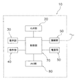
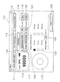
図1に本発明に係る回転速度計の外形図、図2に回転速度計のブロック図を示す。回転速度計10は、被計測物の回転速度を含む各種データを計測するためのもので、センサ部20と、表示手段としての表示部30と、操作部40と、接続部50と、電源供給手段としての電源部60と、制御部70と、記憶手段としてのメモリ部80とから構成される。本実施形態では、周辺機器をパーソナルコンピュータとして記載する。以下、各部の詳細について説明する。
Embodiments of the present invention will be described below with reference to the drawings.
1. Rotation Speed Meter (1) Configuration of Rotation Speed Meter FIG. 1 is an outline view of a rotation speed meter according to the present invention, and FIG. 2 is a block diagram of the rotation speed meter. The
1)センサ部周辺の構造
図3にセンサ部周辺の構造図を示す。センサ部20には、被計測物に対して非接触状態で計測が可能な非接触式計測部21が採用されている。非接触式計測部21は、センサ支持部22と、センサ23とから構成される。センサ支持部22は、回転速度計10から突出した円柱形状の部分であり、センサ23を内蔵している。
1) Structure around the sensor unit Fig. 3 shows a structure around the sensor unit. The
センサ23は、例えばレーザー光線を被計測物に照射する発光部と、被計測物に貼り付けた反射体により反射したレーザー光線を検出するための受光部から構成されている。反射体を貼り付けた被計測物が回転すると、照射したレーザー光線が一定の周期で反射される。反射したレーザー光線は受光部により電気信号に変換され、被計測物の回転速度を計測することができる。
The
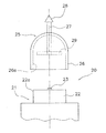
また、計測目的に応じて、被計測物と接触した状態で計測可能とするために、非接触式計測部21に計測補助具25を装着する方法もある。計測補助具25は、支持部26と、軸部27と、接触子28と、反射板29とから構成される。支持部26は、非接触式計測部21に相対回転不能に装着するためのもので、概ねドーム形状を有している。計測補助具25は、支持部26をセンサ支持部22にはめ込み、内周面26aと外周面22aとが当接した状態で装着される。
In addition, there is a method in which the measurement
軸部27は、支持部26の頂点付近を貫通した状態で、支持部26に対して相対回転可能に支持されている。よって、軸部27は、支持部26により非接触式計測部21に対しても相対回転可能に支持される。接触子28は、被計測物に接触させて被計測物の運動を軸部27に回転運動として伝達するためのもので、支持部26に対して被計測物側の軸部27の端部に固定されている。反射板29は、軸部27に伝達された回転を非接触式計測部21により計測可能とするためのもので、軸部27の他端部に相対回転不能に固定された円板状の部材である。
The
接触子28には、計測目的に応じて、例えば円錐形、じょうご形、及びホイール形のものがある。円錐形及びじょうご形接触子は、回転速度を計測する際に使用するためのもので、被計測物の回転体の回転軸中心に軸方向から接触させることで、その回転速度をそのまま軸部27へ伝達することができる。一方、ホイール形接触子は、周速度及び回転長さを計測する際に使用するためのもので、被計測物の回転体の外周側にホイール形接触子の外周側を接触させ、被計測物の周速度をホイール形接触子を介して軸部27に伝達することができる。これらの接触子28により、非接触式計測部21で直接計測できない周速度及び回転長さについても計測することができるようになる。
The
2)表示部周辺の構造
図4に表示部及び操作部周辺の構造図を示す。表示部30は、計測データを表示するためのもので、回転速度計10の中央部分に配置されている。表示部30には、例えば液晶表示装置が採用されている。表示部30の画面は、主表示部31と、副表示部32とから構成される。主表示部31は、計測データの数値を表示する部分である。副表示部32は、計測データの単位等を表示する部分である。
2) Structure around the display unit FIG. 4 shows a structure diagram around the display unit and the operation unit. The
3)操作部周辺の構造
操作部40は、後述する制御部70に指示を与えるためのもので、図4に示すとおり複数のスイッチにより構成されており、回転速度計10の各部に配置されている。操作部40は、電源・計測スイッチ41と、計測切替スイッチ42と、単位切替スイッチ43と、メモリスイッチ44とから構成される。
3) Structure around the operation unit The
電源・計測スイッチ41は、電源の入切及び後述の計測期間を操作するためのもので、回転速度計10の側面に配置された押ボタン式スイッチである。計測切替スイッチ42は、後述する各計測モードを切り替えるためのもので、スライド式スイッチである。単位切替スイッチ43は、表示部30に表示される計測データの単位を切り替えるためのもので、ダイヤル式スイッチである。メモリスイッチ44は、後述する第2計測手段等において操作するためのもので、押ボタン式スイッチである。
The power /
4)接続部周辺の構造
接続部50は、制御部70とパーソナルコンピュータとの間で計測データの通信を可能にするためのもので、図4に示すとおり、回転速度計10の下部に配置されている。接続部50は、USBポート51と、電源入力手段53と、アナログ出力ポート52とから構成される。
4) Structure around the connection section The
USBポート51は、USBケーブルを接続するためのもので、USBポートを搭載したパーソナルコンピュータと回転速度計10とをUSBケーブルを介して接続することができる。USB(Universal Serial Bus)とは、機器同士を結ぶデータ伝送路の規格のひとつであり、パーソナルコンピュータとの通信を可能とする。また、USBポート51は、パーソナルコンピュータの電源を回転速度計10に入力するための経路としても利用できる。
The
電源入力手段53は、USBポート51を介してパーソナルコンピュータから供給された電源を回転速度計10に入力するためのものである。これにより、回転速度計10の電源部の電力の消費を抑えるとともに、電源部から電力が供給できない場合でも、パーソナルコンピュータから電源を確保することができる。
The power input means 53 is for inputting power supplied from a personal computer via the
アナログ出力ポート52は、計測データをアナログ信号として外部に出力するためのものである。例えば、アナログ信号によりデータをプロットできるペンレコーダ等と接続することで、計測データをプロットすることができる。
The
5)電源部の構造
電源供給手段としての電源部60は、回転速度計10の電源を確保するためのものであり、バッテリ式等を採用している。USBポートを介してパーソナルコンピュータから取り込んだ電源を使用することにより、バッテリの電力消費を低減できる。
5) Structure of the power supply unit The
6)制御部
制御部70は、センサ部20からの信号を処理して所望の計測データにするためのもので、後述する各種手段を回転速度計10に実現させるための中枢的な役割を果たしている。制御部70は、図2に示すとおり、センサ部20、表示部30、操作部40、接続部50、電源部60、メモリ部80とそれぞれ接続されており、各部と信号のやりとりを行う。制御部70は、例えばCPU(Central Proccessing Unit)を搭載した小型のコンピュータ等が採用されており、後述する各種手段を実現するようプログラムがされている。
6) Control unit The
7)メモリ部
メモリ部80は、制御部70で処理された計測データを記憶するためのもので、不揮発性メモリを採用している。不揮発性メモリとは、電源を切った状態でも記憶内容を保持することができる半導体メモリのことである。また、記憶できるデータ数を多くするため、従来のメモリに比べてその容量を大きいものにしている。メモリ部80に容量の大きい不揮発性メモリを採用することで、回転速度計10の電源を切った状態でも多くの計測データの記憶を保持でき、記録作業が少なくて済み、計測作業の負担を軽減できる。
7) Memory Unit The
(2)回転速度計の各種手段
制御部70には、回転速度計10に各種手段を実現させるために、プログラムがなされている。以下、回転速度計10がもつ各種手段について説明する。
(2) Various Means of Tachometer The
1)演算手段
演算手段は、センサ部20から入力された信号を所定の計測データに演算処理するためのものである。具体的には、センサ部20の発光部から例えばレーザー光線が被計測物に照射されると、被計測物の回転運動に合わせてレーザー光線が一定周期で反射する。反射したレーザー光線は、受光部により電気信号に変換され、制御部70に入力される。演算手段は、その入力された信号を回転速度等の所定の計測データに演算処理する。演算結果は、各種手段により利用される。
1) Arithmetic means The arithmetic means is for arithmetically processing a signal input from the
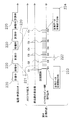
2)第1計測手段
第1計測手段は、所定の周期毎に演算手段により求めた複数の計測データを、表示部30により表示するためのものである。図5に第1計測手段及び第2計測手段の模式図を示す。図5は、上から電源・計測スイッチ41の操作状態、1つのメモリブロックにおける第1計測手段での計測状態、1つのメモリブロックにおける第2計測手段での計測状態を示す。計測期間200は、回転速度計10の電源が入っている状態で電源・計測スイッチ41を押してから放すまでの期間をいう。電源・計測スイッチ41を押すと自動的に計測開始となり、そのまま押した状態にすると、A1から順に一定の計測間隔201おきに演算処理された計測データが表示部30に表示される。電源・計測スイッチ41を放すと計測終了となり待機状態となる。計測間隔201は、あらかじめ設定されており、例えば1秒程度の設定値が考えられる。第1計測手段は、後述の第2計測手段及び第3計測手段の基本となる手段である。
2) 1st measurement means A 1st measurement means is for displaying the some measurement data calculated | required by the calculating means for every predetermined period on the
3)第2計測手段
第2計測手段は、計測期間200中においてメモリスイッチ44の操作により得られた計測データをメモリ部80に記憶させるためのものである。図5に示すとおり、第2計測手段を利用すると、第1計測手段により表示された表示値Anのうち、メモリスイッチ44を押した直前の表示値及び計測時刻203をメモリ部80に記憶させることができる。例えば、メモリスイッチ44を押した瞬間がM1の位置であり、その直前の表示値がA3であれば、A3がM1として記憶される。また、電源を切ると、計測期間200の計測開始日時202、及び計測終了日時、最終値、最大値、最小値、平均値のデータ群204が自動的にメモリ部80に記憶される。1つの計測期間200中に計測した前述のデータ群205は、1つのメモリブロックとして記憶されるため、メモリブロック毎にデータを取扱うことができる。また、メモリ部80が不揮発性メモリを採用しているため、電源を切っても記憶内容は保持される。第2計測手段及び後述の第3計測手段は、計測切替スイッチ42にて切り替えることができる。
3) Second measurement means The second measurement means is for storing the measurement data obtained by operating the
4)第3計測手段
第3計測手段は、計測期間200中の計測データの最終値、最大値、最小値、及び平均値を得るためのものである。図6に第3計測手段の模式図を示す。図6は、上から電源・計測スイッチ41の操作状態、1つのメモリブロックにおける第3計測手段での計測状態を示す。第3計測手段を利用すると、計測期間200中の計測開始日時210、及び計測終了日時、最終値、最大値、最小値、平均値のデータ群211をメモリ部80に記憶させることができる。電源・計測スイッチ41を押すと自動的に計測を開始し、電源・計測スイッチ41を放すと自動的に前述のデータ群212が記憶される。第2計測手段と同様、1つの計測期間200中に計測したデータ群を1つのメモリブロックとして取り扱うことができる。
4) Third measurement means The third measurement means is for obtaining the final value, maximum value, minimum value, and average value of the measurement data during the
5)日時表示手段
日時表示手段は、計測データが得られた日時を表示するためのものでり、また計測データに日時データを付加することも可能としている。前述の第2計測手段及び第3計測手段により計測する際、日時表示手段の日時データが計測時刻、計測開始日時、及び計測終了日時として計測データに付加される。日時データは、計測した年、月、日、時、分、及び秒により構成される。計測時刻は、日時データのうち、時、分、及び秒のみが含まれる。
5) Date and time display means The date and time display means is for displaying the date and time when the measurement data was obtained, and it is also possible to add the date and time data to the measurement data. When measurement is performed by the second measurement unit and the third measurement unit, the date data of the date display unit is added to the measurement data as the measurement time, the measurement start date, and the measurement end date. The date / time data includes the measured year, month, day, hour, minute, and second. The measurement time includes only the hour, minute, and second of the date / time data.
6)日時校正手段
日時校正手段は、日時表示手段の日時をパーソナルコンピュータ側の日時に校正するためのものであり、日時表示手段に含まれている手段である。回転速度計10は、USBポート51を介してパーソナルコンピュータと接続できるため、パーソナルコンピュータから日時データを受け取ることができる。よって、日時表示手段の日時をパーソナルコンピュータ側の日時に合わせることができ、回転速度計10側の日時をパーソナルコンピュータ側の日時に対して正確なものとすることができる。
6) Date and time calibration means The date and time calibration means is for calibrating the date and time of the date and time display means to the date and time on the personal computer side, and is included in the date and time display means. Since the
7)単位切替手段
単位切替手段は、計測目的に応じて計測データの表示単位を操作部40により選択するためのものである。単位切替手段は、副表示部32に表示される単位を単位切替スイッチ43により選択することができる。回転速度計10で使用する単位には、例えば、回転速度としてはrpm、rev/s、周速度としてはcm/s、m/s、m/min、km/h、回転長さとしてはm、km等がある。単位を切り替えると、それに応じて主表示部31に表示される数値も、その単位に換算した数値となる。
7) Unit switching means The unit switching means is for selecting the display unit of the measurement data by the
8)記憶表示手段
記憶表示手段は、メモリ部80に記憶されている計測データの中から、操作部40により選択された計測データを表示部30に表示するためのものである。電源・計測スイッチ41により電源を入れた状態でメモリスイッチ44を押すと、メモリ部80に記憶された計測データを表示部30に表示させることができる。前述の如く、計測データはメモリブロック毎に記憶されており、記憶表示手段においてもメモリブロック毎の計測データを表示させることができる。
8) Storage Display Unit The storage display unit is for displaying the measurement data selected by the
9)記憶消去手段
記憶消去手段は、メモリ部80に記憶された計測データを操作部40により消去するためのものである。記憶表示手段により計測データを表示部30に表示させた場合に、メモリスイッチ44を一定時間(例えば5秒間)押すと、最後に記憶されたメモリブロックの計測データを消去することができる。
9) Memory Erasing Unit The memory erasing unit is for erasing the measurement data stored in the
10)電源切替手段
電源切替手段は、パーソナルコンピュータから供給された電源と、電源部60から供給された電源とを切替するためのものである。回転速度計10に前述のUSBポート51を介してパーソナルコンピュータから電源が供給された際に、自動的にパーソナルコンピュータから供給された電源を選択させることができる。また、パーソナルコンピュータとの接続が切断されると、電源部60から供給される電源へ自動的に切り替わる。電源が入っていない状態であれば、自動的に回転速度計10の電源が入る。
10) Power supply switching means The power supply switching means is for switching between the power supplied from the personal computer and the power supplied from the
2.プログラム
本発明に係る回転速度計10は、前述の如く、パーソナルコンピュータとのUSBによる接続、及び計測データの通信を考慮して設計されている。それに伴い、パーソナルコンピュータにおいても、回転速度計10の操作、計測データの受信、及び計測データの処理等を可能とするプログラムが必要となってくる。以下に、本発明に係る回転速度計10に対応したパーソナルコンピュータのプログラムについて説明する。
2. Program The
(1)パーソナルコンピュータの構成
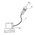
本プログラムは、パーソナルコンピュータに回転速度計10と通信する機能を実現させるためのものである。図7に回転速度計とパーソナルコンピュータとの通信状態図を示す。回転速度計10は、前述の如くUSBポート51を備えており、USBケーブル11によりパーソナルコンピュータ90と接続することができる。図8にパーソナルコンピュータの構成図を示す。パーソナルコンピュータ90は、主に、処理装置91と、表示装置92と、記憶装置93と、操作装置94と、接続装置95と、電源装置96とから構成される。
(1) Configuration of Personal Computer This program is for causing a personal computer to realize a function of communicating with the
処理装置91は、図8に示すとおり、パーソナルコンピュータ90の中枢を成す装置であり、例えばCPU等から校正されている。本プログラムは、処理装置91において動作する。表示装置92は、回転速度計10との接続状態や計測データ等を表示するためのものである。記憶装置93は、回転速度計10から取り込んだ計測データを記憶するためのものである。操作装置94は、処理装置91に対して指示を与えるためのものである。接続装置95は、USBケーブル11を接続するためのもので、回転速度計10と同様USBポートを有している。よって、パーソナルコンピュータ90の処理装置91は、接続装置95及び接続部50を介して、回転速度計10の制御部70に接続されている。電源装置96は、パーソナルコンピュータ90の電源を確保するためのもので、ACアダプタやバッテリ等がある。
As shown in FIG. 8, the
本プログラムは、パーソナルコンピュータ90に、回転速度計10と通信し計測データを取り込む等の各種手段を実現させる。以下に各種手段について説明する。
This program causes the
(2)プログラムの各種手段
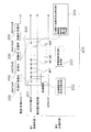
プログラムを起動させると、操作が可能なよう表示装置92に各モードに応じた画面が出力される。図9にプログラム動作時の画面構成図の一例を示す。プログラム動作時の計測手段としては、主に、主計測手段と、第4計測手段と、第5計測手段と、第6計測手段とがある。それに応じて、画面も主計測画面110と、第4計測画面130と、第5計測画面150と、第6計測画面170とから構成される。
(2) Various means of the program When the program is started, a screen corresponding to each mode is output to the
1)主計測手段
主計測手段は、プログラムを動作させた場合の初期状態で使用する手段であり、主計測画面110から操作する。図10に主計測画面の構成図の一例を示す。主計測手段では、主に、回転速度計10との接続状態の確認や後述の各モードへの切替を行うことができる。以下、各種手段について操作方法とともに説明する。
1) Main measurement means The main measurement means is used in the initial state when the program is operated, and is operated from the
(a)日時校正手段
日時校正手段は、回転速度計10の日時表示手段の日時をパーソナルコンピュータ90のシステム日時に校正するためのものである。主計測画面110の日時校正ボタン114を選択すると、回転速度計10の日時表示手段の日時を日時表示部111に表示されているシステム日時に合わせることができる。
(A) Date and time calibration means The date and time calibration means is for calibrating the date and time of the date and time display means of the
(b)状態表示手段
状態表示手段は、回転速度計10の状態を表示させるためのものである。主計測画面110の数値表示部112に、回転速度計10のバッテリの状態、回転速度計10との接続状態、計測データ及び単位が表示される。接続状態は、接続チェックボタン115により、手動で確認することができる。
(B) Status display means The status display means is for displaying the status of the
(c)単位切替手段
単位切替手段は、計測データの表示単位を切り替えるためのものである。単位切替ボタン113により所望の表示単位を選択できる。単位の種類は、前述の如く、回転速度と、周速度と、回転長さとがあり、回転速度計10の単位切替スイッチ43で選択可能な単位と同様である。回転速度計10がパーソナルコンピュータ90と通信している場合は、単位切替ボタン113にて選択された単位を優先適用するようになっている。
(C) Unit switching means The unit switching means is for switching the display unit of measurement data. A desired display unit can be selected by the
(d)記憶消去手段
記憶消去手段は、回転速度計10のメモリ部80に記憶されている計測データを消去するためのものである。主計測画面110にはクリアボタン119、122が設けられており、クリアボタン119、122により前述の第2計測手段及び第3計測手段にて計測した計測データをそれぞれ別々に消去することができる。例えば、クリアボタン119を選択すると、第2計測手段にて計測した計測データをメモリ部80から遠隔操作により消去できる。なお、回転速度計10に記憶されている計測データの件数が、メモリ件数表示118、121に表示される。
(D) Memory Erasing Unit The memory erasing unit is for erasing the measurement data stored in the
(e)モード切替手段
モード切替手段は、後述する第4、第5、及び第6計測手段への切替をするものである。主計測画面110には第4計測手段ボタン116、第5計測手段ボタン117、及び第6計測手段ボタン118が設けられている。各ボタンを選択すると、対応する各手段及び各画面に切り替わる。
(E) Mode switching means The mode switching means switches to fourth, fifth, and sixth measuring means described later. The
(f)アナログ出力選択手段
アナログ出力選択手段は、計測データのアナログ出力値のスケールを設定するためのものである。主計測画面110にはスケールを設定するためのアナログスケールセル124が設けられている。
(F) Analog output selection means The analog output selection means is for setting the scale of the analog output value of the measurement data. The
(g)計測間隔選択手段
計測間隔選択手段は、回転速度計10がデータを計測する間隔を選択するためのものである。主計測画面110には間隔選択ボタン123が設けられており、例えば、「0.5秒」を選択すると、回転速度計10は0.5秒おきに計測データを処理する。
(G) Measurement interval selection means The measurement interval selection means is for selecting an interval at which the
(h)その他の手段
その他、プログラムを終了させたい場合は、終了ボタン125を選択することによりプログラムは終了する。
(H) Other Means In addition, when it is desired to end the program, the program is ended by selecting the
2)第4計測手段
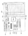
第4計測手段は、回転速度計10にて計測したデータをリアルタイムでパーソナルコンピュータ90側に取り込むためのものである。図11に第4計測画面の構成図の一例、図12に第4計測手段の模式図を示す。図10に示す主計測画面110の第4計測手段ボタン116を選択すると、主計測手段から第4計測手段へ切り替わり、画面も第4計測画面130に切り替わる。
2) Fourth measuring means The fourth measuring means is for taking data measured by the
(a)リスト表示手段
リスト表示手段は、回転速度計10からリアルタイムで取り込んだ計測データをリストにて表示するためのものである。図11に示す計測ボタン136を選択すると、計測データの取り込みが開始され、取り込まれた計測データがリスト137に表示される。計測データの取り込みについては、図12に基づいて説明する。図12は、上から電源・計測スイッチ41の操作状態、1つのメモリブロックにおける第4計測手段での計測状態を示す。回転速度計10からパーソナルコンピュータ90への計測データの取り込みは、一定の取込周期222おきに行われる。取り込みを行う直前に回転速度計10にて処理された計測データが取り込みの対象となる。例えば、取り込み直前の回転速度計10側の表示値がC3であれば、C3がパーソナルコンピュータ90側の表示値D3としてリスト137に表示される。よって、回転速度計10の計測データを全て取り込みたい場合は、取込周期222は計測間隔221よりも短くしておく必要がある。
(A) List display means The list display means is for displaying the measurement data taken in real time from the
取込周期222は、図11に示す取込周期選択ボタン142にて選択できる。計測中に計測ボタン136を選択すると、計測データの取り込みは終了する。計測開始時及び終了時の計測データは、図12に示すとおり、計測開始日時及び計測終了日時が付加されたデータ群223、224となっている。計測データの取り込みが終了すると、計測期間220中に取り込んだ計測データ中の最大値、最小値、平均値、及びデータ件数がそれぞれ図11に示す最大値セル138、最小値セル139、平均値セル140、及びデータ件数セル141に表示される。
The
(b)グラフ表示手段
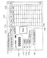
グラフ表示手段は、リスト表示手段により取り込んだ計測データをグラフ表示するためのものである。図11に示すグラフボタン135を選択すると、画面がグラフ表示画面146に切り替わる。図13にグラフ表示画面の構成図の一例を示す。計測データは、縦軸147を表示値、横軸148を計測時刻としてグラフにて表示される。縦軸147の表示単位は、主計測画面110の単位切替ボタン113により選択された単位を採用する。終了ボタン149を選択すると、図11に示す第4計測画面130に切り替わる。
(B) Graph display means The graph display means is for displaying the measurement data captured by the list display means in a graph. When the
(c)データ保存手段
データ保存手段は、リスト表示手段により取り込んだ計測データを記憶装置に記憶させるためのものである。図11に示すデータ保存ボタン134を選択すると、リスト137に表示されている計測データが記憶装置に記憶される。計測データは、様々なアプリケーションソフトでの利用を考慮し、例えば、CSV形式にて記憶される。CSV(Conmma Separated Values)形式とは、記憶されたデータ中の各フィールドをコンマ(“,”)で区切って並べたファイル形式のことで、データの汎用性が高くなる。
(C) Data storage means The data storage means is for storing the measurement data captured by the list display means in a storage device. When the data save
(d)トリガー手段
トリガー手段は、計測データの設定値を基準に計測開始及び停止を行うためのものである。図11に示すトリガー設定セル143にて計測開始及び停止する基準値を設定する。基準値設定後、計測ボタン136を選択すると、表示値が基準値より小さい場合は待機状態となる。また、表示値が基準値より大きくなると自動的に計測を開始する。計測中の状態は、前述のリスト表示手段及びグラフ表示手段と同様である。計測データの値がトリガー設定値より小さくなると、自動的に計測終了となる。計測ボタン136を再度選択すると、トリガー手段による計測は終了となる。
(D) Trigger means The trigger means is for starting and stopping measurement based on the set value of measurement data. A reference value for starting and stopping measurement is set in the
3)第5計測手段
第5計測手段は、回転速度計10に記憶されている計測データをパーソナルコンピュータ90側に取り込むためのものである。図14に第5計測画面の構成図の一例を示す。図10に示す主計測画面110の第5計測手段ボタン117を選択すると、主計測手段から第5計測手段へ切り替わり、画面も第5計測画面150に切り替わる。
3) Fifth measuring means The fifth measuring means is for taking in the measurement data stored in the
(a)リスト表示手段
リスト表示手段は、回転速度計10に記憶されている計測データを取り込み、リストにて表示するためのものである。図14に示す取込ボタン155を選択すると、回転速度計10に記憶された計測データのうち、前述の第2計測手段にて計測された計測データが全てパーソナルコンピュータ90側に取り込まれ、リスト156に表示される。回転速度計10に記憶されている計測データは、前述の如く、計測時刻、及び単位情報も付加されたデータとなっている。
(A) List display means The list display means takes in the measurement data stored in the
(b)データ保存手段
ファイル保存手段は、リスト表示手段により取り込んだ計測データを記憶装置93に記憶させるためのものである。図14に示すデータ保存ボタン154を選択すると、リスト156に表示されている計測データが記憶装置93に記憶される。計測データは、例えばCSV形式にて記憶される。
(B) Data storage means The file storage means is for storing the measurement data captured by the list display means in the
(c)記憶消去手段
記憶消去手段は、回転速度計10に記憶された計測データを遠隔操作により消去するためのものである。図14に示す記憶消去ボタン161を選択すると、回転速度計10に記憶された計測データのうち、前述の第2計測手段にて計測された計測データのみが回転速度計10のメモリ部80から消去される。
(C) Memory erasure means The memory erasure means is for erasing the measurement data stored in the
4)第6計測手段
第6計測手段は、回転速度計10に記憶されている計測データをパーソナルコンピュータ90側に取り込むためのものである。図15に第6計測画面の構成図の一例を示す。主計測画面110の第6計測手段ボタン120を選択すると、主計測手段から第6計測手段へ切り替わり、画面も第6計測画面170に切り替わる。
4) Sixth measuring means The sixth measuring means is for taking the measurement data stored in the
(a)リスト表示手段
リスト表示手段は、回転速度計10に記憶されている計測データを取り込み、リストにて表示するためのものである。図15に示す取込ボタン175を選択すると、回転速度計10に記憶された計測データのうち、前述の第3計測手段にて計測された計測データが全てパーソナルコンピュータ90側に取り込まれ、リスト176に表示される。回転速度計10に記憶されている計測データは、計測時刻、及び単位情報も付加されたデータとなっている。
(A) List display means The list display means takes in the measurement data stored in the
(b)データ保存手段
ファイル保存手段は、リスト表示手段により取り込んだ計測データを記憶装置93に記憶させるためのものである。図15に示すデータ保存ボタン174を選択すると、リスト176に表示されている計測データが記憶装置に記憶される。計測データは、CSV形式にて記憶される。
(B) Data storage means The file storage means is for storing the measurement data captured by the list display means in the
(c)記憶消去手段
記憶消去手段は、回転速度計10に記憶された計測データを遠隔で消去するためのものである。図15に示す記憶消去ボタン181を選択すると、回転速度計10に記憶された計測データのうち、前述の第3計測手段にて計測された計測データのみがメモリ部80から消去される。
(C) Memory erasing means The memory erasing means is for remotely erasing the measurement data stored in the
3.本発明の作用効果
本発明の作用効果を以下にまとめる。
3. Effects of the Present Invention The effects of the present invention are summarized below.
この回転速度計10では、接続部50がUSBポート51を有しているため、USB搭載機器であるパーソナルコンピュータ90にUSBポート51を介して計測データを送信することができ、回転速度計10の使用者がパーソナルコンピュータ90により計測データを電子データとして保存、利用することが容易となる。パーソナルコンピュータは様々なアプリケーションソフトを備えているため、使用者は目的に応じて適切なソフト等を利用し、計測データの整理、編集を行うことができる。その結果、計測データの利便性を高めることができる。
In the
また、この回転速度計10は接続部50が電源入力手段53を有しているため、USBポート51を介してパーソナルコンピュータ90の電源の一部を利用することができ、回転速度計に内蔵されたバッテリ等の消費を抑えることができる。またこの回転速度計10は、電源部60及び電源切替手段を備えているため、パーソナルコンピュータ90からの電源が入力されない場合でも、電源部60により電源のバックアップが可能となる。さらに、この回転速度計10は、パーソナルコンピュータ90からUSBポート51を介して電源が入力された場合に、優先的にその電源を選択することができ、電源部60の電力の消費を抑えることができる。
Further, since the
この回転速度計10では、第1計測手段により、所定の周期毎に演算処理を行った複数の計測データを表示部30に表示させることができるため、連続して計測した際に計測データの確認が容易となる。また、この回転速度計10では、不揮発性メモリを採用しているため、小容量の揮発性メモリを採用している従来の回転速度計に比べて、多くの計測データを長時間保存することができ、一度に多くの計測が可能となる。
In this
この回転速度計10では、日時表示手段を備えているため、計測データがいつ計測されたものかを容易に把握することができ、計測データを整理、編集する際に便利である。また、日時校正手段を備えているため、使用者は日時表示手段の日時をパーソナルコンピュータ90側の日時に容易に校正することができ、計測データの計測した日時がパーソナルコンピュータ90の日時表示に対して正確なものとすることができる。
Since the
以上より、本発明に係る回転速度計10は、計測したデータを一時的に確認するだけでなく、USBポート51を介してUSB搭載機器との通信を行うことにより、計測データを電子データとして送信することが可能となる。また、計測データに計測した日時を付加することができる。その結果、回転速度計10の使用者は、USB搭載機器で計測データを容易に保存、利用、整理、及び編集等することができるため、本発明に係る回転速度計10により、従来に比べて計測データの利便性を高めることができる。
As described above, the
4.その他の実施形態
本発明は係る上記実施形態に限定されるものではなく、本発明の範囲を逸脱することなく種々の変形又は修正が可能である。以下に他の実施形態について説明する。
4). Other Embodiments The present invention is not limited to the above-described embodiments, and various changes and modifications can be made without departing from the scope of the present invention. Other embodiments will be described below.
1)USB搭載機器
前述の実施形態では、USB搭載機器をパーソナルコンピュータ90として記載したが、USBを搭載していればこれに限定されない。例えば、PDA(Personal Degital Assistance)などの携帯情報端末等でもよい。
1) USB-equipped device In the above-described embodiment, the USB-equipped device is described as the
2)センサ部
前述の実施形態では、センサ部20は非接触式として記載したが、これに限定されない。例えば、非接触式計測部21に計測補助具25を装着して接触式としていたが、センサ部20に接触式計測部を設けてもよい。
2) Sensor part Although the
10 回転速度計
20 センサ部
21 非接触式計測部
30 表示部
40 操作部
41 電源・計測スイッチ
42 計測切替スイッチ
43 単位切替スイッチ
44 メモリスイッチ
50 接続部
51 USBポート
52 アナログ出力ポート
60 電源部
70 制御部
80 メモリ部
90 パーソナルコンピュータ
110 主計測画面
130 第4計測画面
146 グラフ表示画面
150 第5計測画面
170 第6計測画面
DESCRIPTION OF
Claims (8)
前記被計測物の回動を感知してその回動量に伴う信号を出力するセンサ部と、
前記センサ部からの信号が入力され、前記信号を所定の計測データに演算処理する演算手段と、
前記計測データを記憶する記憶手段と、
前記計測データを表示するための表示手段と、
他のUSB(Universal Serial Bus)搭載機器に対して前記計測データの通信を行うためのUSBと、
を備えた回転速度計。 A portable tachometer for measuring various data including the rotation speed of the object to be measured,
A sensor unit that senses the rotation of the object to be measured and outputs a signal associated with the amount of rotation;
A calculation means for inputting a signal from the sensor unit and calculating the signal into predetermined measurement data;
Storage means for storing the measurement data;
Display means for displaying the measurement data;
A USB for communicating the measurement data to other USB (Universal Serial Bus) devices;
Tachometer equipped with.
請求項1に記載の回転速度計。 Power supply input means for inputting the power supplied from the USB device via the USB,
The rotation speed meter according to claim 1.
請求項1または2に記載の回転速度計。 The USB-equipped device is a personal computer.
The tachometer according to claim 1 or 2.
請求項1から3のいずれかに記載の回転速度計。 For each predetermined period, the calculation unit performs the calculation process to obtain a plurality of measurement data, and the display unit includes a first measurement unit that displays the plurality of measurement data.
The tachometer according to any one of claims 1 to 3.
請求項1から4のいずれかに記載の回転速度計。 A date and time display means for displaying the date and time when the measurement data was obtained;
The tachometer according to any one of claims 1 to 4.
請求項1から5のいずれかに記載の回転速度計。 The date and time display means includes date and time calibration means for calibrating the date and time of the date and time display means so as to match the date and time display provided in the USB device.
The tachometer according to any one of claims 1 to 5.
請求項1から6のいずれかに記載の回転速度計。 The storage means is a nonvolatile memory capable of storing the measurement data even when no power is input.
The tachometer according to any one of claims 1 to 6.
前記電源供給手段からの電源と前記USB搭載機器から前記USBを介して入力される電源とのいずれかを選択して切り替える電源切替手段を備えた、
請求項1から7のいずれかに記載の回転速度計。 Power supply means for securing a power supply;
Comprising power switching means for selecting and switching between the power from the power supply means and the power input from the USB-equipped device via the USB;
The tachometer according to any one of claims 1 to 7.
Priority Applications (1)
| Application Number | Priority Date | Filing Date | Title |
|---|---|---|---|
| JP2004105615A JP2005291850A (en) | 2004-03-31 | 2004-03-31 | Tachometer |
Applications Claiming Priority (1)
| Application Number | Priority Date | Filing Date | Title |
|---|---|---|---|
| JP2004105615A JP2005291850A (en) | 2004-03-31 | 2004-03-31 | Tachometer |
Publications (1)
| Publication Number | Publication Date |
|---|---|
| JP2005291850A true JP2005291850A (en) | 2005-10-20 |
Family
ID=35324949
Family Applications (1)
| Application Number | Title | Priority Date | Filing Date |
|---|---|---|---|
| JP2004105615A Pending JP2005291850A (en) | 2004-03-31 | 2004-03-31 | Tachometer |
Country Status (1)
| Country | Link |
|---|---|
| JP (1) | JP2005291850A (en) |
Cited By (3)
| Publication number | Priority date | Publication date | Assignee | Title |
|---|---|---|---|---|
| KR100791319B1 (en) | 2006-01-11 | 2008-01-03 | (주) 그린텍아이엔씨 | Ultrasonic Doppler Flowmeter for Sewer Pipe |
| JP2014219744A (en) * | 2013-05-02 | 2014-11-20 | 日置電機株式会社 | Measurement device |
| US12355402B2 (en) | 2020-08-19 | 2025-07-08 | Kyocera International Inc. | Wideband amplifier linearization techniques |
-
2004
- 2004-03-31 JP JP2004105615A patent/JP2005291850A/en active Pending
Cited By (3)
| Publication number | Priority date | Publication date | Assignee | Title |
|---|---|---|---|---|
| KR100791319B1 (en) | 2006-01-11 | 2008-01-03 | (주) 그린텍아이엔씨 | Ultrasonic Doppler Flowmeter for Sewer Pipe |
| JP2014219744A (en) * | 2013-05-02 | 2014-11-20 | 日置電機株式会社 | Measurement device |
| US12355402B2 (en) | 2020-08-19 | 2025-07-08 | Kyocera International Inc. | Wideband amplifier linearization techniques |
Similar Documents
| Publication | Publication Date | Title |
|---|---|---|
| US8942940B2 (en) | Portable articulated arm coordinate measuring machine and integrated electronic data processing system | |
| US8615893B2 (en) | Portable articulated arm coordinate measuring machine having integrated software controls | |
| KR101178774B1 (en) | Fishing reel, fishing data display device, and fishing data display system | |
| CN104520665A (en) | Handheld measuring instrument | |
| WO2020096873A2 (en) | Orbital welding device with simplified handling | |
| JP2005291850A (en) | Tachometer | |
| US20190286093A1 (en) | Controller, control method, and control program | |
| JP2015513669A (en) | Portable articulated arm coordinate measuring machine with integrated software control | |
| EP3341152B1 (en) | A sensor module for a fabrication tool and manufacturing method | |
| JP2596264Y2 (en) | Pointer load torque measuring instrument | |
| RU104309U1 (en) | DEVICE FOR MEASURING MICROCLIMATE PARAMETERS | |
| CN113295121A (en) | Hand-push roller distance measuring instrument, hand-push roller distance measuring instrument monitoring device and distance measuring system | |
| CN223966047U (en) | Film thickness measuring device | |
| KR101644297B1 (en) | Cutting angle measurement apparatus | |
| CA2995002C (en) | A sensor module for a fabrication tool | |
| CN116576808A (en) | Digital space measuring method and device, measuring device | |
| KR200250885Y1 (en) | Easy-to-use portable meter having an automatic calibration function | |
| JPH07320019A (en) | Sensor card and measuring device using the same | |
| JP2004268234A (en) | Grinding attachment and its control method | |
| JP2009160105A (en) | Biological information measuring device | |
| KR20040047135A (en) | Laser | |
| JP2008125865A (en) | Sewing production control equipment |
Legal Events
| Date | Code | Title | Description |
|---|---|---|---|
| A621 | Written request for application examination |
Free format text: JAPANESE INTERMEDIATE CODE: A621 Effective date: 20070201 |
|
| A521 | Written amendment |
Free format text: JAPANESE INTERMEDIATE CODE: A821 Effective date: 20070613 |
|
| RD04 | Notification of resignation of power of attorney |
Free format text: JAPANESE INTERMEDIATE CODE: A7424 Effective date: 20070613 |
|
| A977 | Report on retrieval |
Free format text: JAPANESE INTERMEDIATE CODE: A971007 Effective date: 20090728 |
|
| A131 | Notification of reasons for refusal |
Free format text: JAPANESE INTERMEDIATE CODE: A131 Effective date: 20090731 |
|
| A02 | Decision of refusal |
Free format text: JAPANESE INTERMEDIATE CODE: A02 Effective date: 20091120 |