JP2005291828A - Sonic speed measuring method and device using ultrasonic microscope, and image diagnosing method and device - Google Patents
Sonic speed measuring method and device using ultrasonic microscope, and image diagnosing method and device Download PDFInfo
- Publication number
- JP2005291828A JP2005291828A JP2004105214A JP2004105214A JP2005291828A JP 2005291828 A JP2005291828 A JP 2005291828A JP 2004105214 A JP2004105214 A JP 2004105214A JP 2004105214 A JP2004105214 A JP 2004105214A JP 2005291828 A JP2005291828 A JP 2005291828A
- Authority
- JP
- Japan
- Prior art keywords
- pulse
- excitation
- reflected wave
- wave signal
- ultrasonic
- Prior art date
- Legal status (The legal status is an assumption and is not a legal conclusion. Google has not performed a legal analysis and makes no representation as to the accuracy of the status listed.)
- Granted
Links
- 238000000034 method Methods 0.000 title claims description 36
- 230000005284 excitation Effects 0.000 claims abstract description 118
- 238000012935 Averaging Methods 0.000 claims abstract description 20
- 230000005279 excitation period Effects 0.000 claims abstract description 14
- 238000005259 measurement Methods 0.000 claims description 56
- 230000008569 process Effects 0.000 claims description 13
- 238000002059 diagnostic imaging Methods 0.000 claims description 12
- 238000002405 diagnostic procedure Methods 0.000 claims description 9
- 238000000691 measurement method Methods 0.000 claims description 6
- 238000000605 extraction Methods 0.000 claims 2
- 238000012545 processing Methods 0.000 description 54
- 238000002360 preparation method Methods 0.000 description 34
- 238000003745 diagnosis Methods 0.000 description 20
- 238000001228 spectrum Methods 0.000 description 13
- 238000010586 diagram Methods 0.000 description 8
- 230000006870 function Effects 0.000 description 8
- 238000012937 correction Methods 0.000 description 6
- 230000015654 memory Effects 0.000 description 6
- 230000001360 synchronised effect Effects 0.000 description 6
- XLYOFNOQVPJJNP-UHFFFAOYSA-N water Substances O XLYOFNOQVPJJNP-UHFFFAOYSA-N 0.000 description 5
- 230000005540 biological transmission Effects 0.000 description 4
- 238000010186 staining Methods 0.000 description 4
- 238000006243 chemical reaction Methods 0.000 description 3
- 230000003111 delayed effect Effects 0.000 description 2
- 238000002474 experimental method Methods 0.000 description 2
- 230000003902 lesion Effects 0.000 description 2
- 230000003287 optical effect Effects 0.000 description 2
- 238000011160 research Methods 0.000 description 2
- 238000012827 research and development Methods 0.000 description 2
- 238000000926 separation method Methods 0.000 description 2
- 238000001356 surgical procedure Methods 0.000 description 2
- 230000009897 systematic effect Effects 0.000 description 2
- 230000001225 therapeutic effect Effects 0.000 description 2
- 238000002604 ultrasonography Methods 0.000 description 2
- 230000003936 working memory Effects 0.000 description 2
- AHVPOAOWHRMOBY-UHFFFAOYSA-N 2-(diethylamino)-1-[6,7-dimethoxy-1-[1-(6-methoxynaphthalen-2-yl)ethyl]-3,4-dihydro-1h-isoquinolin-2-yl]ethanone Chemical compound C1=C(OC)C=CC2=CC(C(C)C3C4=CC(OC)=C(OC)C=C4CCN3C(=O)CN(CC)CC)=CC=C21 AHVPOAOWHRMOBY-UHFFFAOYSA-N 0.000 description 1
- 230000003321 amplification Effects 0.000 description 1
- 230000002238 attenuated effect Effects 0.000 description 1
- 230000000903 blocking effect Effects 0.000 description 1
- 201000011510 cancer Diseases 0.000 description 1
- 230000008859 change Effects 0.000 description 1
- 230000001934 delay Effects 0.000 description 1
- 238000001514 detection method Methods 0.000 description 1
- 238000011161 development Methods 0.000 description 1
- 230000000694 effects Effects 0.000 description 1
- 239000012776 electronic material Substances 0.000 description 1
- 238000011156 evaluation Methods 0.000 description 1
- 239000011521 glass Substances 0.000 description 1
- 230000006872 improvement Effects 0.000 description 1
- 230000001678 irradiating effect Effects 0.000 description 1
- 238000003199 nucleic acid amplification method Methods 0.000 description 1
- 230000008520 organization Effects 0.000 description 1
- 230000010355 oscillation Effects 0.000 description 1
- 230000001575 pathological effect Effects 0.000 description 1
- 230000000704 physical effect Effects 0.000 description 1
- 238000007781 pre-processing Methods 0.000 description 1
- 230000009467 reduction Effects 0.000 description 1
- 230000004044 response Effects 0.000 description 1
- 238000007447 staining method Methods 0.000 description 1
- 238000009210 therapy by ultrasound Methods 0.000 description 1
- 230000007704 transition Effects 0.000 description 1
Images



Classifications
-
- G—PHYSICS
- G01—MEASURING; TESTING
- G01N—INVESTIGATING OR ANALYSING MATERIALS BY DETERMINING THEIR CHEMICAL OR PHYSICAL PROPERTIES
- G01N29/00—Investigating or analysing materials by the use of ultrasonic, sonic or infrasonic waves; Visualisation of the interior of objects by transmitting ultrasonic or sonic waves through the object
- G01N29/04—Analysing solids
- G01N29/06—Visualisation of the interior, e.g. acoustic microscopy
- G01N29/0609—Display arrangements, e.g. colour displays
-
- G—PHYSICS
- G01—MEASURING; TESTING
- G01N—INVESTIGATING OR ANALYSING MATERIALS BY DETERMINING THEIR CHEMICAL OR PHYSICAL PROPERTIES
- G01N2291/00—Indexing codes associated with group G01N29/00
- G01N2291/02—Indexing codes associated with the analysed material
- G01N2291/028—Material parameters
- G01N2291/02854—Length, thickness
-
- G—PHYSICS
- G01—MEASURING; TESTING
- G01N—INVESTIGATING OR ANALYSING MATERIALS BY DETERMINING THEIR CHEMICAL OR PHYSICAL PROPERTIES
- G01N2291/00—Indexing codes associated with group G01N29/00
- G01N2291/02—Indexing codes associated with the analysed material
- G01N2291/028—Material parameters
- G01N2291/0289—Internal structure, e.g. defects, grain size, texture
Landscapes
- Physics & Mathematics (AREA)
- Acoustics & Sound (AREA)
- Health & Medical Sciences (AREA)
- Life Sciences & Earth Sciences (AREA)
- Chemical & Material Sciences (AREA)
- Analytical Chemistry (AREA)
- Biochemistry (AREA)
- General Health & Medical Sciences (AREA)
- General Physics & Mathematics (AREA)
- Immunology (AREA)
- Pathology (AREA)
- Investigating Or Analyzing Materials By The Use Of Ultrasonic Waves (AREA)
- Ultra Sonic Daignosis Equipment (AREA)
Abstract
Description
この発明は、超音波顕微鏡を使用した音速測定方法、その音速測定装置、超音波顕微鏡を使用した画像診断方法およびその画像診断装置に関する。詳しくは超音波顕微鏡として特に、広帯域のパルス励起型超音波顕微鏡を使用して生体組織などの被測定物の音速を測定するに当たり、超音波振動子を間欠的に励起する期間内の一部期間を利用して集中的に複数のパルス励起を行って反射波信号を得ると共に、集中的に取得したこれら反射波信号を平均化することで、測定時間を犠牲にすることなく被測定物からの反射波信号のS/N(C/N)を改善して高解像化を図れる超音波顕微鏡を使用した音速測定方法およびその音速測定装置に関する。 The present invention relates to a sound velocity measuring method using an ultrasonic microscope, a sound velocity measuring device thereof, an image diagnostic method using an ultrasonic microscope, and an image diagnostic device thereof. Specifically, as an ultrasonic microscope, especially when measuring the speed of sound of a measurement object such as a living tissue using a broadband pulse excitation type ultrasonic microscope, a part of the period during which the ultrasonic transducer is intermittently excited The reflected wave signal is obtained by performing a plurality of pulse excitations intensively using the, and by averaging the reflected wave signals acquired intensively, the measurement time from the object to be measured is not sacrificed. The present invention relates to a sound speed measuring method using an ultrasonic microscope capable of improving the S / N (C / N) of a reflected wave signal and achieving high resolution, and a sound speed measuring apparatus thereof.
さらに、生体組織などの性状を音速像として取得するに当たり、高S/Nの音速情報に基づいて生体組織の音速像が得られる超音波顕微鏡を使用した画像診断方法およびその画像診断装置に関する。 Further, the present invention relates to an image diagnostic method using an ultrasonic microscope and an image diagnostic apparatus thereof that can obtain a sound velocity image of a living tissue based on sound velocity information of high S / N when acquiring properties such as a living tissue as a sound velocity image.
超音波顕微鏡を使用して試料の表面状態を観察したり、その音速を測定する手法は以前から知られている(例えば、非特許文献1)。 A technique for observing the surface state of a sample using an ultrasonic microscope and measuring the speed of sound has been known (for example, Non-Patent Document 1).
また、一方では生体組織の観察及び診断に、この超音波顕微鏡などが応用されるようになってきた。例えば、悪性腫瘍を切除するような場合、切除部位の組織を摘出したり、切除部位近傍の生体組織を摘出して組織観察する生体組織診断が行われている。 On the other hand, this ultrasonic microscope has been applied to the observation and diagnosis of living tissue. For example, when a malignant tumor is excised, biological tissue diagnosis is performed in which the tissue at the excision site is removed or the biological tissue near the excision site is excised and observed.
この生体組織診断に使用される診断装置(観察装置)として従来から光学顕微鏡が使用されている。これは摘出した生体組織を染色した状態でその切除面を光学顕微鏡で観察しているが、完全な染色を行うには1日以上待機しなければならないため、光学顕微鏡を使用した組織観察は術後になる。 Conventionally, an optical microscope has been used as a diagnostic apparatus (observation apparatus) used for this biological tissue diagnosis. In this state, the excised surface is observed with an optical microscope in a state where the extracted living tissue is stained. However, in order to perform complete staining, it is necessary to wait for one day or more. Later.
また、染色する場合でも術中に観察が可能なように術中迅速診断法も開発されているが、この場合には、通常の染色による場合には組織輪郭の内部に「染色によって塗り分けられる」はずの組織情報が、術中迅速診断法では失われてしまうことが報告されている。 In addition, an intraoperative rapid diagnosis method has been developed so that observation can be performed during surgery even when staining is performed. In this case, in the case of normal staining, the tissue outline should be “colored by staining”. It has been reported that the tissue information is lost by intraoperative rapid diagnosis.
このようなことから、従来の染色方法を用いないでも、術中に摘出した生体組織の診断を行える術中診断法や、術中診断装置の開発が切望されている。この要望に応えるものとして、超音波顕微鏡を使用した診断装置の研究および開発がなされている。 For this reason, development of an intraoperative diagnostic method and an intraoperative diagnostic apparatus capable of diagnosing a living tissue extracted during surgery without using a conventional staining method is eagerly desired. In response to this demand, research and development of a diagnostic apparatus using an ultrasonic microscope has been conducted.
超音波顕微鏡とは、生体組織に超音波を照射し、その反射波の強度や位相などを演算処理して可視像化しながら観察することで、その生体組織を診断する手法である(例えば非特許文献1参照)。 An ultrasonic microscope is a technique for diagnosing a living tissue by irradiating the living tissue with ultrasonic waves and observing the reflected wave intensity and phase, etc. while processing and visualizing it (for example, non-contrast). Patent Document 1).
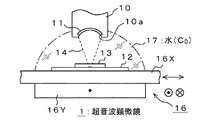
図7はこれを模式的に示した概念図であって、超音波顕微鏡1は送受波部10を有する。この送受波部10にはその先端部側に超音波振動子11が内蔵されている。送受波部10と対峙するようにガラス板などを使用したプレパラート(試料載置板)12が置かれ、このプレパラート12上に被測定物(例えば、生体組織切片)13が載置される。
FIG. 7 is a conceptual diagram schematically showing this, and the
そして、この被測定物13をターゲットとするように被測定物面に対して、超音波が水などの媒質17を介して照射される。超音波出射面10aは図示するように湾曲しており、超音波はビーム状に絞り込まれた状態で被測定物13の面に到達するようになされている。ビームの絞り込み方などで分解能が決まる。
Then, ultrasonic waves are applied to the surface of the object to be measured through the
被測定物13の面上を二次元走査できるように、この例では二次元走査手段16が設けられ、この二次元走査手段16に上述したプレパラート12が載置される。図7の例では、二次元走査手段16としてX−Yステージを使用した場合を示す。X−Yステージ16はXステージ16XとYステージ16Yとで構成される。
In this example, a two-
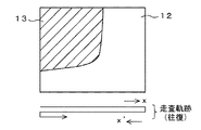
したがって、超音波出射側からの平面図は図8のようになり、また図9のようにx、x’方向(水平方向)への往復走査と、y方向への走査を行うことによって被測定物13に対して超音波を二次元的に走査することができる。
Therefore, the plan view from the ultrasonic wave emission side is as shown in FIG. 8, and as shown in FIG. 9, the measurement is performed by performing reciprocal scanning in the x and x ′ directions (horizontal direction) and scanning in the y direction. The
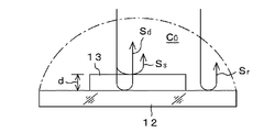
超音波顕微鏡1は音波の伝搬という定量化が容易な物理的パラメータを取り扱うのが特長である。具体的には反射波(反射波信号)の強度や位相をパラメータとして取り扱う。反射波を可視像として観察するため、図10のようにプレパラート12の面上に照射された超音波の反射波信号(参照反射波信号)Srと、被測定物13の面上に照射された超音波の反射波信号Soが利用される。
The
ここに、反射波信号Soは、被測定物13の表面から反射した反射波信号Ssと、その裏面側つまりプレパラート12の面で反射した反射波信号Sdとの干渉波である。
Here, the reflected wave signal So is an interference wave between the reflected wave signal Ss reflected from the surface of the
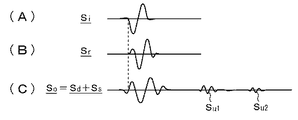
図11には超音波振動子11を従来のようにバースト信号で励起するのではなく、説明の都合上、広帯域のパルス信号で励起したときのそれぞれの波形が示されている。
FIG. 11 shows respective waveforms when the
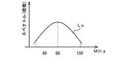
図11Aは超音波振動子11を励起する励起パルスSiの波形である。ほぼ1サイクルのパルス波形で、その周波数特性は図12のようになる。この例では、中心周波数が80MHz程度で、40〜150MHz程度までの帯域を持つ励起パルスが使用される。図11Bはそのとき得られる参照反射波信号Srの波形である。また図11Cは反射波信号SsとSdとが干渉した干渉反射波信号Soの波形が示されている。
FIG. 11A shows a waveform of an excitation pulse Si that excites the
図示する干渉反射波信号Soは、被測定物13として生体組織切片を用いたときの波形で、励起パルスSi自身の波形(Si’)のほかに、反射波信号Suが得られる。超音波は超音波振動子11と被測定物13との間で繰り返し反射されるものであるから、最初に得られる反射波信号を一次反射波信号Su1とすると、数次に至った反射波信号Su2,Su3,・・・が得られる。
The interference reflected wave signal So shown in the figure is a waveform when a biological tissue section is used as the
ここで、このような構成をなす超音波顕微鏡にあっては、得られた反射波信号Sr,Soの強度(反射波強度)や位相を利用して試料の音速が求められる。測定精度を高めるためには、S/Nのよい反射波信号を得ることのできる測定方法や測定装置であることが望ましい。また、この超音波顕微鏡を生体の画像診断として利用する場合には、被測定物13は摘出した生体組織切片となる。
Here, in the ultrasonic microscope having such a configuration, the sound velocity of the sample is obtained using the intensity (reflected wave intensity) and phase of the obtained reflected wave signals Sr and So. In order to increase the measurement accuracy, it is desirable that the measurement method or the measurement apparatus can obtain a reflected wave signal with a good S / N. When this ultrasonic microscope is used for image diagnosis of a living body, the
以下に画像診断について説明する。生体組織切片からの反射波の強度や位相に基づいて生体組織を評価することで、当該生体組織内における音響減衰評価が可能になる。 Image diagnosis will be described below. By evaluating the living tissue based on the intensity and phase of the reflected wave from the living tissue section, it is possible to evaluate the acoustic attenuation in the living tissue.
非特許文献2にも示されるように、従来におけるバースト信号を利用した超音波顕微鏡による診断ではこのように音響減衰による評価が主で、したがって、従来では生体組織の音速評価は全くなされていない。生体組織内に超音波を照射した場合、超音波は生体組織の性状によって得られる音速が相違することが知られている。
As shown in Non-Patent
つまり、生体組織と音速とは相関性が高く、生体組織が正常な組織である場合と、病変部のように変質した組織の場合とでは、その物理的性質の違い、換言すれば生体組織の弾性の違いが音速の違いとなって検知できる。 In other words, there is a high correlation between living tissue and sound velocity, and the difference in physical properties between the case where the living tissue is a normal tissue and the case where the tissue is altered like a lesion, in other words, the living tissue. Differences in elasticity can be detected as differences in sound speed.
超音波を使用する場合では、音響特性の相違から生体組織の違いとして「塗り分ける」ことが可能であることが、最近の諸種の実験によって確認されている。したがって、超音波による生体組織の性状診断を行うには、生体組織の音響特性をミクロンレベルで計測することが必要になる。 In the case of using ultrasonic waves, it has been confirmed by various kinds of recent experiments that it can be “painted” as a difference in biological tissue from a difference in acoustic characteristics. Therefore, in order to perform a property diagnosis of a living tissue using ultrasonic waves, it is necessary to measure the acoustic characteristics of the living tissue at a micron level.
その一方で、術中診断を可能にするためには、
(1)摘出生体組織切片の迅速な可視像生成が可能であること
(2)できれば、超音波顕微鏡を使用した診断装置の手術室内への搬入が可能であること
(3)診断のための装置操作が簡易であること
(4)目視できること
などの諸種の課題をクリアしなければならない。
On the other hand, to enable intraoperative diagnosis,
(1) It is possible to quickly generate a visible image of an excised living tissue section (2) If possible, it is possible to carry a diagnostic device using an ultrasonic microscope into an operating room (3) For diagnosis It is necessary to clear various problems such as simple operation of the apparatus (4) being visible.
さらには、商業ベースを考えると、比較的安価に提供できることも必要である。あまり高価であると、装置設置者にとって負担が大きく、その負担の一部は患者への医療費負担に還元されてしまうからである。 Furthermore, considering a commercial base, it is also necessary to be able to provide it at a relatively low cost. This is because if the cost is too high, the burden on the apparatus installer is large, and a part of the burden is reduced to the medical cost burden on the patient.
さて、従来の超音波顕微鏡を使用した診断装置は、上述したように単一周波数のバースト信号を超音波信号として利用し、反射した超音波信号の強度や位相を解析することで、生体組織の性状を観察している。 A diagnostic apparatus using a conventional ultrasonic microscope uses a single-frequency burst signal as an ultrasonic signal as described above, and analyzes the intensity and phase of the reflected ultrasonic signal, so that Observe the properties.
プレパラート12から直接反射された参照反射波信号Srと生体組織切片13からの反射波信号Soを用いて生体組織切片13の厚みdや生体組織の音速を算出することができる。その詳細は後述する。
Using the reference reflected wave signal Sr directly reflected from the
ところで、上述した表面反射波信号Ssと裏面反射波信号Sdとの時間差よりも、超音波振動子11に加えるバースト信号の持続時間を短くすることが難しいため、通常は表面反射波信号Ssと裏面反射波信号Sdとが互いに干渉した干渉反射波信号Soを用いて解析せざるを得ない。
By the way, since it is difficult to shorten the duration of the burst signal applied to the
干渉による影響をなくすため、干渉波を分離できるようにバースト信号の周波数を順次変化させて、そのときの反射波の強度と位相スペクトルを解析することで、生体組織の厚さと音速を算出している。 In order to eliminate the influence of interference, the burst signal frequency is sequentially changed so that the interference wave can be separated, and the intensity and phase spectrum of the reflected wave at that time are analyzed to calculate the thickness and sound speed of the living tissue. Yes.
研究室レベルで研究開発が進行しているこの超音波顕微鏡を使用した診断装置では、上述したようにバースト信号を使用した位相検波方式を採用している。上述したように得られた反射波の強度と位相スペクトルを解析して、生体組織の厚みや音速を算出し、得られた音響特性から生体組織の性状を診断するものであるから、可視像化するまでの処理時間が非常に長い。 In the diagnostic apparatus using the ultrasonic microscope, which is under research and development at the laboratory level, the phase detection method using the burst signal is adopted as described above. Analyzing the intensity and phase spectrum of the reflected wave obtained as described above, calculating the thickness and speed of sound of the living tissue, and diagnosing the properties of the living tissue from the obtained acoustic characteristics, so a visible image It takes a very long time to process.
例えば、2mm×2mmの生体組織切片を100×100ピクセルとして測定した場合でも10分以上費やしてしまう。したがってこれを300×300ピクセル程度まで測定精度を上げるためには90分程度の処理時間がかかることになり、病理判断を行う術中診断装置としては充分とは言えない。 For example, even when a 2 mm × 2 mm biological tissue section is measured as 100 × 100 pixels, it takes 10 minutes or more. Therefore, in order to increase the measurement accuracy up to about 300 × 300 pixels, it takes about 90 minutes of processing time, which is not sufficient as an intraoperative diagnostic apparatus for performing pathological judgment.
計測時間が長くかかるのは、さらに生体組織切片に対する走査速度が関与している。従来装置では生体組織切片をX−Yステージ16の上に載せ、これをx、y方向に間欠的に動かすことで、例えば100×100ピクセルの生体像を得ている。この間欠走査による生体像の取得が測定時間を遅延させる大きな要因となっている。さらに生体組織の切片から得られた反射波を処理して音速情報を得る信号処理速度の遅さも一因となっている。
The long measurement time further involves the scanning speed of the biological tissue section. In the conventional apparatus, a biological tissue section is placed on the
このような問題を解決するための超音波顕微鏡を使用した画像診断装置として、近年パルス励起による超音波顕微鏡を使用した画像診断装置の研究が進められている。 As an image diagnostic apparatus using an ultrasonic microscope for solving such a problem, research on an image diagnostic apparatus using an ultrasonic microscope based on pulse excitation has recently been advanced.
上述したようにほぼ1サイクル分の広帯域パルスを用いて超音波振動子を励起する方式である。このパルス励起型超音波顕微鏡を用いると共に、X−Yステージ16のx、y方向における走査速度を速め、さらに信号処理系を工夫することによって、超音波を照射してから最終的な診断画像を可視像として描画するまでの時間を、従来のバースト信号を使用した超音波顕微鏡よりも格段に短縮できることが確認された。
As described above, this is a method of exciting an ultrasonic transducer using a broadband pulse for approximately one cycle. By using this pulse excitation type ultrasonic microscope, the scanning speed in the x and y directions of the
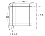
本出願人らによる実験によれば、図13のように、参照面としてのプレパラート12を含めた300×300ピクセルの画像を描画する場合でも2分以下に短縮できることが判った。もちろん、このような画像処理時間の短縮は、同時に超音波を収束させて照射する超音波ビームを使用したこと、超音波の励起周波数(ほぼ中心周波数)を80MHz程度に選定することなどが大きく寄与していることは明らかである。
According to the experiments by the present applicants, it was found that even when an image of 300 × 300 pixels including the
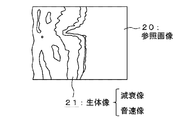
図14に超音波顕微鏡を使用して作成した生体組織の画像(生体像)の一例を示す。プレパラート12の面が参照画像20となり、生体組織切片が生体像21となって得られる。生体像は減衰像や音速像が考えられる。
FIG. 14 shows an example of a biological tissue image (biological image) created using an ultrasonic microscope. The surface of the
このようなパルス励起による超音波顕微鏡を使用した高速処理を可能にした画像診断装置にあって、超音波を照射したときの反射波から、照射点(測定点)での生体組織の音速を正確に算出するには、その前提として第1に被測定物(試料)の載置面の超音波に対する傾きがゼロであること(換言すれば、載置面が傾いていないこと)、第2に、得られた反射波信号のS/Nが良いことが少なくとも必要である。 In this diagnostic imaging device that enables high-speed processing using an ultrasonic microscope with pulse excitation, the sound velocity of biological tissue at the irradiation point (measurement point) is accurately determined from the reflected wave when irradiated with ultrasonic waves. As a precondition for the calculation, first, the inclination of the mounting surface of the object to be measured (sample) to the ultrasonic wave is zero (in other words, the mounting surface is not inclined), and secondly It is necessary at least that the S / N of the obtained reflected wave signal is good.
第1の課題に対しては、生体組織と超音波振動子(トランスデューサ)11が正対し、図10のように参照基板であるプレパラート12や生体組織切片13に対してそれぞれ直角に超音波が照射されることが必要である。 For the first problem, the living tissue and the ultrasonic transducer (transducer) 11 face each other, and as shown in FIG. It is necessary to be done.
生体組織切片13はプレパラート12の上に載せられており、このプレパラート12はさらにX−Yステージ16に載っているものであるから、超音波振動子11とプレパラート12および生体組織切片13がそれぞれ正対の関係にあるとは限らず、微少ではあるが、僅かな傾きを以て正対する場合が殆どである。この傾きがゼロでないと、参照反射波信号Srおよび干渉反射波信号Soから音速を正確に算出することができず、僅かな計測誤差が発生してしまう。
Since the
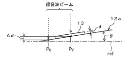
例えば、図15に示すように基準面refに対してプレパラート12の平面12aが傾きθをもっているときには、参照点Poと生体組織切片13が載置されているところの測定点Ppとの関係では、測定点Ppは、z軸方向(超音波出射方向)に対して参照点PoよりもΔdだけずれている。
For example, as shown in FIG. 15, when the plane 12a of the
このz軸方向での測定点Ppのずれによって、音速の算出誤差が生じ、この誤差による影響で、より精密で、きめ細かな画像診断の妨げとなるおそれがある。 The deviation of the measurement point Pp in the z-axis direction causes a sound speed calculation error, which may hinder a more precise and detailed image diagnosis due to the error.
特に、生体組織切片を観察するときは、この生体組織切片を極めて薄く切り落として使用する。通常4〜10μm程度の厚みとなるようにスライスする。これに対してプレパラート12の傾きは微調整後であっても1μm程度の調整誤差(傾き誤差)が発生しているのが常である。しかし、この調整誤差は生体組織切片の厚みからすると看過できない値であるから、極めて高精度に調整して、傾きを限りなくゼロに近づけなければならない。
In particular, when observing a biological tissue section, the biological tissue section is cut out very thinly and used. Usually, it slices so that it may become a thickness of about 4-10 micrometers. On the other hand, the inclination of the
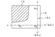
このずれΔdを機械的に補正する場合が考えられる。例えば図16に示すように生体組織切片13が載置されていないプレパラート12の平面12aの任意の点Poを基準点とし、これとx軸方向での任意の点P1およびy軸方向での任意の点P2をとり、基準点Poからみたプレパラート12のx軸方向の傾き(Δθx)がゼロとなるようにプレパラート12より、具体的にはXステージ16Xのx軸方向の傾きが微調整される。同様にしてy軸方向の傾き(Δθy)がゼロとなるようにYステージ16Yの傾きが微調整される。
A case where the deviation Δd is mechanically corrected can be considered. For example, as shown in FIG. 16, an arbitrary point Po on the plane 12a of the
このような機械的な微調整を繰り返し行うことで、超音波の出射方向とプレパラート12および生体組織切片13のそれぞれが直交するようになるので、音速の算出精度が高まる。
By repeatedly performing such mechanical fine adjustment, the ultrasonic wave emission direction and each of the
X−Yステージ16の超音波出射方向に対する傾きθは上述したように極めて僅かな値であるから、これを正確に微調整するためには相当の熟練を要するため、生体組織を診断する前の調整時間に相当時間を費やすことになる。結果として迅速で高精度な生体組織診断を阻害する要因となっている。しかも、この機械的な微調整は、熟練を要すると共に、生体組織を診断する都度実施しなければならないので、非常に面倒であるなどの問題も惹起しているので、電気的に補正することが試みられている。なお、電気的に補正することに関しては本発明の内容と共に説明することとする。
Since the inclination θ of the
パルス励振型の超音波顕微鏡や超音波治療装置としては特許文献1〜特許文献3などが知られている。
特許文献1は、パルス増幅器からのノイズを遮断するためのスイッチ回路を備えた超音波顕微鏡が開示されている。したがってこの発明とは直接関係のない技術である。
特許文献2は、パルス励振型超音波治療装置に関する技術であって、特にパルスの焦点位置がずれないような治療装置に関するもので、これまたこの発明の内容とは直接関係がない。
また、特許文献3は、三次元超音波顕微鏡に関する技術が開示されている。これは球面超音波によって三次元に対象物を観察できるようにしたもので、二次元観察を対象とするこの発明とはその技術が相違する。
ところで、このようなパルス励起による超音波顕微鏡を使用した高速処理を可能にした音速測定にあっては、超音波を照射したときに得られる反射波信号SoやSrのS/N(又はC/N、以下同じ)が大きくなければならない。画像診断装置にあっても、照射点(計測点)での生体組織の音速を正確に算出するには、反射波信号SoやSrのS/Nがよくなければならない。つまり上述した第2の課題を解決する必要がある。しかし、実際には得られる反射波信号のレベルは非常に低い。 By the way, in the sound velocity measurement that enables high-speed processing using an ultrasonic microscope by pulse excitation, the S / N (or C / C) of the reflected wave signal So or Sr obtained when the ultrasonic wave is irradiated. N, the same shall apply hereinafter) must be large. Even in the diagnostic imaging apparatus, the S / N of the reflected wave signals So and Sr must be good in order to accurately calculate the sound speed of the living tissue at the irradiation point (measurement point). That is, it is necessary to solve the second problem described above. However, in practice, the level of the reflected wave signal obtained is very low.
図11Cに示すように励起パルスSiに対応した反射波信号Si’に対し、実際に生体組織から得られる反射波信号Suのレベルは数分の1以下あるいはそれ以上の開きがある。 As shown in FIG. 11C, the level of the reflected wave signal Su actually obtained from the living tissue with respect to the reflected wave signal Si ′ corresponding to the excitation pulse Si has a difference of a fraction or less.
しかもこの反射波信号Si’には外来ノイズなどが混入し易い。さらには、超音波振動子11を励起する励起パルスSiに僅かなジッタがあると、測定精度に影響を及ぼすことになる。
Moreover, external noise or the like is likely to be mixed in the reflected wave signal Si ′. Furthermore, if there is a slight jitter in the excitation pulse Si for exciting the
反射波信号SuのS/Nを高めるためには、その受信部のゲインを大きくしたり、あるいは同一測定点での励起パルスを1回ではなく、数回行えばよい。前者の場合にはノイズの問題がある。後者の場合には、複数回の励起によって得られた反射波信号を総和して平均したり、増幅処理を行うことで、S/Nを高めることができる。 In order to increase the S / N ratio of the reflected wave signal Su, the gain of the receiving unit may be increased, or the excitation pulse at the same measurement point may be performed several times instead of once. In the former case, there is a problem of noise. In the latter case, the S / N can be increased by summing and averaging the reflected wave signals obtained by a plurality of excitations or performing amplification processing.
しかし、そうすると複数の測定点を間欠的に測定していることになるので、励起パルスの繰り返し回数分だけ測定時間がかかることになり、高速処理の隘路となる。高速処理を確保した状態で、S/Nの高い反射波信号を得る必要がある。 However, since a plurality of measurement points are measured intermittently in such a case, the measurement time is increased by the number of repetitions of the excitation pulse, which becomes a bottleneck for high-speed processing. It is necessary to obtain a reflected wave signal having a high S / N while ensuring high-speed processing.
このようなことから、超音波顕微鏡を用いて音速を測定する場合にあっては、反射波信号のS/Nが音速測定精度に影響を及ぼすことから、S/Nを改善することが極めて重要になる。そのことが結果として超音波顕微鏡を用いた画像診断装置に対する画像診断に大きく影響を及ぼすことになる。 For this reason, when measuring the speed of sound using an ultrasonic microscope, the S / N of the reflected wave signal affects the sound speed measurement accuracy, so it is extremely important to improve the S / N. become. As a result, this greatly affects the image diagnosis for the image diagnosis apparatus using the ultrasonic microscope.
そこで、この発明はこのような従来の課題を解決したものであって、間欠的に励起する間隔の中で集中的に複数回のパルス励起を行うことで、高速処理を担保したまま反射波信号のS/Nを高めることができるようにした、超音波顕微鏡を使用した音速測定方法、音速測定装置及びS/Nのよい反射波信号を用いた画像診断方法およびその画像診断装置を提案するものである。 Therefore, the present invention solves such a conventional problem, and performs reflected wave signal while ensuring high-speed processing by performing pulse excitation multiple times in an interval of intermittent excitation. Proposing a sound speed measurement method using an ultrasonic microscope, a sound speed measurement device, an image diagnosis method using a reflected wave signal having a good S / N, and an image diagnosis device for the same It is.
上述の課題を解決するため、請求項1に記載したこの発明に係る超音波顕微鏡を使用した音速測定方法は、超音波振動子をパルス励起することで被測定物の音速を測定するパルス励起型超音波顕微鏡を使用した音速測定方法であって、
励起パルスで上記超音波振動子を間欠的に励起すると共に、この間欠的な励起パルス間隔の中で集中的に複数個の励起パルスを短時間に励起する集中パルス励起ステップと、
この集中パルス励起期間中に得られる上記励起パルスからの反射波信号を平均化するステップと、
平均化した反射波信号に基づいて、上記被測定物の音速を算出するステップとを有することを特徴とする。
In order to solve the above-mentioned problem, a sound speed measuring method using an ultrasonic microscope according to the present invention described in
A concentration pulse excitation step of exciting the ultrasonic transducer intermittently with an excitation pulse and simultaneously exciting a plurality of excitation pulses in a short time in the intermittent excitation pulse interval;
Averaging the reflected wave signal from the excitation pulse obtained during the lumped pulse excitation period;
And calculating a sound speed of the object to be measured based on the averaged reflected wave signal.
請求項8に記載したこの発明に係る超音波顕微鏡を使用した音速測定装置は、超音波振動子をパルス励起することで被測定物の音速を測定するパルス励起型超音波顕微鏡を使用した音速測定装置であって、
上記超音波振動子に加える励起パルスの間欠励起間隔の中で、集中的に複数個の励起パルスを短時間に励起する集中パルス励起機能を有したパルサー部と、
上記被測定物を二次元走査する二次元走査手段と、
当該二次元走査手段に対する駆動手段と、
この駆動手段に供給される駆動パルスの生成手段と、
上記超音波振動子より得られる反射波信号を上記集中パルス励起期間ごとに平均化する信号演算手段とで構成され、
上記駆動パルス生成手段から上記パルサー部にパルス励起用のトリガー信号が供給されると共に、上記信号演算手段での平均化された信号が反射波信号として利用されることを特徴とする。
The sound speed measurement apparatus using the ultrasonic microscope according to the present invention described in
In the intermittent excitation interval of the excitation pulse applied to the ultrasonic vibrator, a pulsar unit having a concentrated pulse excitation function for exciting a plurality of excitation pulses in a short time in a concentrated manner,
Two-dimensional scanning means for two-dimensionally scanning the object to be measured;
Driving means for the two-dimensional scanning means;
Drive pulse generation means to be supplied to the drive means;
The signal calculation means for averaging the reflected wave signal obtained from the ultrasonic transducer for each of the concentrated pulse excitation periods,
A trigger signal for pulse excitation is supplied from the drive pulse generation means to the pulsar unit, and an averaged signal from the signal calculation means is used as a reflected wave signal.
また、請求項12に記載したこの発明に係る超音波顕微鏡を使用した画像診断方法は、超音波振動子をパルス励起することで被測定物の性状を音速像として取得するパルス励起型超音波顕微鏡を使用した画像診断方法であって、
励起パルスで上記超音波振動子を間欠的に励起すると共に、この間欠的な励起パルス間隔の中で集中的に複数個の励起パルスを短時間に励起する集中パルス励起ステップと、
この集中パルス励起期間中に得られる上記励起パルスからの反射波信号を平均化するステップと、
平均化した反射波信号に基づいて、上記被測定物の厚みを算出するステップと、
算出された上記厚みを用いて、上記被測定物の音速像を生成するための音速を算出するステップとを有することを特徴とする。
According to a twelfth aspect of the present invention, there is provided a diagnostic imaging method using an ultrasonic microscope according to the present invention, wherein a pulse excitation type ultrasonic microscope that obtains a property of an object to be measured as a sound velocity image by pulse exciting an ultrasonic transducer A diagnostic imaging method using
A concentration pulse excitation step of exciting the ultrasonic transducer intermittently with an excitation pulse and simultaneously exciting a plurality of excitation pulses in a short time in the intermittent excitation pulse interval;
Averaging the reflected wave signal from the excitation pulse obtained during the lumped pulse excitation period;
Calculating the thickness of the object to be measured based on the averaged reflected wave signal;
And calculating a sound velocity for generating a sound velocity image of the object to be measured using the calculated thickness.
また、請求項16に記載したこの発明に係る超音波顕微鏡を使用した画像診断装置は、超音波振動子をパルス励起することで被測定物の性状を音速像として取得するパルス励起型超音波顕微鏡を使用した画像診断装置であって、
上記超音波振動子に加える励起パルスの間欠励起間隔の中で、集中的に複数個の励起パルスを短時間に励起する集中パルス励起機能を有したパルサー部と、
上記被測定物を二次元走査する二次元走査手段と、
当該二次元走査手段に対する駆動手段と、
この駆動手段に供給される駆動パルスの生成手段と、
上記超音波振動子より得られる反射波信号を上記集中パルス励起期間ごとに平均化する信号演算手段と、
上記信号演算手段での平均化された反射波信号に基づいて上記被測定物の音速の算出と、算出した音速に基づいて音速像を生成する手段とで構成されたことを特徴とする。
According to a sixteenth aspect of the present invention, there is provided an image diagnostic apparatus using the ultrasonic microscope according to the present invention, wherein a pulse excitation type ultrasonic microscope that obtains a property of an object to be measured as a sound velocity image by pulse exciting an ultrasonic transducer. A diagnostic imaging apparatus using
In the intermittent excitation interval of the excitation pulse applied to the ultrasonic vibrator, a pulsar unit having a concentrated pulse excitation function for exciting a plurality of excitation pulses in a short time in a concentrated manner;
Two-dimensional scanning means for two-dimensionally scanning the object to be measured;
Driving means for the two-dimensional scanning means;
Drive pulse generation means to be supplied to the drive means;
A signal calculating means for averaging the reflected wave signal obtained from the ultrasonic transducer for each of the concentrated pulse excitation periods;
It is characterized by comprising calculation of the sound speed of the object to be measured based on the averaged reflected wave signal in the signal calculation means, and means for generating a sound speed image based on the calculated sound speed.
この発明では、X−Yステージは連続走査である。しかし、超音波振動子を励起するのは間欠的となる。この間欠的な励起期間の中で、さらに集中して複数個の励起パルスで短時間に超音波振動子を励起する。こうすることで、X−Yステージが連続走査した状態でも、ほぼ同一の測定点に対して超音波を照射することができる。そして、短時間のうちに複数回、超音波振動子を励起することで、複数個の反射波信号が得られる。これら複数個の反射波信号を平均化すれば、S/Nの高い反射波信号が得られる。 In the present invention, the XY stage is continuous scanning. However, it is intermittent to excite the ultrasonic transducer. During this intermittent excitation period, the ultrasonic transducer is excited in a short time with a plurality of excitation pulses. By so doing, even when the XY stage is continuously scanned, it is possible to irradiate ultrasonic waves to almost the same measurement point. Then, a plurality of reflected wave signals are obtained by exciting the ultrasonic transducer a plurality of times in a short time. If these plural reflected wave signals are averaged, a reflected wave signal having a high S / N can be obtained.
平均化するための反射波信号は一次反射波信号である。超音波振動子とプレパラートあるいは生体組織切片との間では多重反射が行われるから、この例ではそのうち最初に得られる反射波信号(一次反射波信号)を用いる。 The reflected wave signal for averaging is a primary reflected wave signal. Since multiple reflection is performed between the ultrasonic transducer and the preparation or the biological tissue section, in this example, a reflected wave signal (primary reflected wave signal) obtained first is used.
そのために、この一次反射波信号のみを抽出するためのゲートパルスを生成する。ゲートパルスは超音波振動子を励起する励起パルスに同期した信号から生成される。こうすることで、励起パルス生成のためのトリガー信号にたとえジッタがあったとしても、そのジッタの影響を受けることのないゲートパルスを生成できる。 Therefore, a gate pulse for extracting only the primary reflected wave signal is generated. The gate pulse is generated from a signal synchronized with the excitation pulse for exciting the ultrasonic transducer. By doing so, even if there is jitter in the trigger signal for generating the excitation pulse, it is possible to generate a gate pulse that is not affected by the jitter.
この発明では、生体組織などの画像診断を行うに当たっては、上述したS/N改善効果の高い一次反射波信号を利用する。この一次反射波信号と参照反射波信号の位相差などから生体組織切片の厚みが算出されると共に、この厚みから生体組織切片の音速が算出される。同一音速同士をつなぎ合わせることで得られる等音速線をモニタに描画することで生体組織の音速像が得られる。この音速像から生体組織を診断できる。 In the present invention, the above-described primary reflected wave signal having a high S / N improvement effect is used when performing an image diagnosis of a living tissue or the like. The thickness of the biological tissue slice is calculated from the phase difference between the primary reflected wave signal and the reference reflected wave signal, and the sound velocity of the biological tissue slice is calculated from the thickness. A sound velocity image of a living tissue can be obtained by drawing on the monitor an isosonic line obtained by connecting the same sound speeds. A living tissue can be diagnosed from this sound velocity image.
この発明では、超音波振動子が間欠的に励起されると共に、この間欠的な励起期間の中でさらに駐中してパルス励振を複数回短時間に行ったときの反射波信号を平均化した信号を反射波信号として使用するようにしたものである。 In the present invention, the ultrasonic transducer is intermittently excited, and the reflected wave signal is averaged when the pulse excitation is performed a plurality of times in a short period of time during the intermittent excitation period. The signal is used as a reflected wave signal.
これによれば、平均化された反射波信号であるのでS/N(またはC/N)が改善される。さらに、超音波振動子から出射した超音波信号に基づいて一次反射波信号をゲートするようにしたから、平均化する一次反射波信号のジッタがなくなりそれだけ高精度な一次反射波信号を抽出できる。 According to this, since it is an averaged reflected wave signal, S / N (or C / N) is improved. Furthermore, since the primary reflected wave signal is gated on the basis of the ultrasonic signal emitted from the ultrasonic transducer, the jitter of the averaged primary reflected wave signal is eliminated and a highly accurate primary reflected wave signal can be extracted.
さらに、この発明ではこの高S/N処理、低ジッタ処理された反射波信号に基づいて被測定物の音速を求め、この音速から被測定物の音速像を生成するようにしたものである。 Further, in the present invention, the sound speed of the object to be measured is obtained based on the reflected wave signal subjected to the high S / N processing and the low jitter process, and the sound speed image of the object to be measured is generated from the sound speed.
これによれば、S/Nのよい反射波信号を利用する関係で、高精度で高精細な可視像を得ることができるので高精度、高精密な画像診断を実現できる。 According to this, a high-precision and high-definition visible image can be obtained because a reflected wave signal having a good S / N is used, so that high-precision and high-precision image diagnosis can be realized.
続いて、この発明に係る超音波顕微鏡を使用した音速測定方法、その音速測定装置、画像診断方法およびその画像診断装置の好ましい実施例を図面を参照して詳細に説明する。 Next, preferred embodiments of a sound speed measuring method using the ultrasonic microscope according to the present invention, a sound speed measuring device, an image diagnostic method, and an image diagnostic device will be described in detail with reference to the drawings.
被測定物として生体組織切片を例示する。図17は傾き補正を電気的に行うための原理的説明に供する図である。以下に示す実施例としては、被測定物として生体組織の切片を用いてその厚みおよび音速を測定することで、生体組織の音速像を得るものに適用した例を述べる。 A biological tissue section is illustrated as an object to be measured. FIG. 17 is a diagram for explaining the principle for electrically performing tilt correction. As an example shown below, an example is described in which a slice of a living tissue is used as an object to be measured and its thickness and sound speed are measured to obtain a sound velocity image of the living tissue.
機械的調整によってプレパラート12の傾きを調整するのではなく、電気的な処理でこの機械的な傾きを補正するには、まずプレパラート12の平面方程式を解く必要がある。X−Yステージ16の傾きはプレパラート12の傾きに反映されるので、結局は生体組織切片13を載置しているプレパラート12の傾きを補正すればよいことになる。
Rather than adjusting the inclination of the
プレパラート12が傾いた状態での任意の点での平面方程式が算出できれば、その平面方程式によって表されるz軸の値そのものが傾きを含んだ値となっているので、生体組織切片13の厚みdをこの平面方程式を利用して算出するだけで、傾きを考慮した厚み算出となる。つまり、傾きによる影響を排除して厚みが算出されたことになる。
If the plane equation at an arbitrary point in the state where the
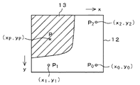
そのため、図17のように生体組織切片13が載置されていないプレパラート12の平面12aにおける任意の3点Po,P1,P2を指定する。そのうちの1点例えばPo(xo,yo)を参照点とする。残りの2点P1,P2の座標を(x1,y1)、(x2,y2)とする。
Therefore, arbitrary three points Po, P1, and P2 on the plane 12a of the
平面方程式は周知のように、
Z=ax+by+c ・・・・・(1)
(ここに、a,b,cは係数である)
である。したがって3点Po,P1,P2の平面方程式Zo,Z1,Z2は
Zo=axo+byo+c ・・・・・(2)
Z1=ax1+by1+c ・・・・・(3)
Z2=ax2+by2+c ・・・・・(4)
参照点Poの傾きは、基準点であるためゼロ(Zo=0)とする。
(2)〜(4)式から、係数a,b,cは、
As is well known, the plane equation is
Z = ax + by + c (1)
(Where a, b, and c are coefficients)
It is. Therefore, the plane equations Zo, Z1, Z2 of the three points Po, P1, P2 are Zo = axo + byo + c (2)
Z1 = ax1 + by1 + c (3)
Z2 = ax2 + by2 + c (4)
The inclination of the reference point Po is zero (Zo = 0) because it is a reference point.
From the equations (2) to (4), the coefficients a, b, and c are
となる。 It becomes.
したがって、生体組織切片13が載置されているプレパラート12の任意の測定点Px(xp、yp)での平面方程式は、上述した係数a,b,cから
Zp=axp+byp+c ・・・・・(6)
となる。このz軸方向の値Zp、すなわち参照点Poと測定点Pxとのz軸方向における距離差分Zpを傾き補正値として、その測定点Pxにおける厚みdpが算出される。
Accordingly, the plane equation at an arbitrary measurement point Px (xp, yp) of the
It becomes. Using the value Zp in the z-axis direction, that is, the distance difference Zp in the z-axis direction between the reference point Po and the measurement point Px, the thickness dp at the measurement point Px is calculated.
上述した測定点P1,P2での平面方程式Z1,Z2は以下のようにして算出できる。まず、各点Po,P1,P2での反射波信号Sro,Sr1,Sr2を得る。 The plane equations Z1 and Z2 at the measurement points P1 and P2 described above can be calculated as follows. First, the reflected wave signals Sro, Sr1, Sr2 at the points Po, P1, P2 are obtained.
次に、これら反射波信号Sro,Sr1,Sr2の周波数成分を得るためフーリエ変換(例えば高速フーリエ変換FFT)処理を施す。それぞれのフーリエ変換出力Fo,F1,F2から参照点Poを基準にしたフーリエ変換出力の比(F1/Fo)および(F2/Fo)を求める。このフーリエ変換出力の比は規格化スペクトルとなる。 Next, in order to obtain frequency components of these reflected wave signals Sro, Sr1, and Sr2, Fourier transform (for example, fast Fourier transform FFT) processing is performed. The ratios (F1 / Fo) and (F2 / Fo) of the Fourier transform outputs based on the reference point Po are obtained from the respective Fourier transform outputs Fo, F1, and F2. The ratio of the Fourier transform output is a normalized spectrum.
次に、この規格化スペクトルに関連した複素平面(周波数に対する位相の関係)より、φ/2πf(fは超音波信号の中心周波数)を求める。このφ/2πfは、結局参照点Poと測定点P1との間の傾きによって生ずる時間差Δto1となる。同様に参照点Poと測定点P2との傾きによって生ずる時間差Δto2が求まる。 Next, φ / 2πf (f is the center frequency of the ultrasonic signal) is obtained from a complex plane (phase relationship with respect to frequency) related to the normalized spectrum. This φ / 2πf eventually becomes the time difference Δto1 caused by the inclination between the reference point Po and the measurement point P1. Similarly, a time difference Δto2 caused by the inclination between the reference point Po and the measurement point P2 is obtained.
したがって、参照点Poと測定点P1までのz軸方向の値が、すなわち平面方程式Z1であり、これは超音波振動子10とプレパラート12との間に介在された媒質(通常は水)の音速をCoとしたとき、
Z1=Co・Δto1 ・・・・(7)
として求めることができる。Coは既知の値(=1600m/s)である。同様に、測定点P2における平面方程式Z2は、
Z2=Co・Δto2 ・・・・(8)
となり、これらの値Z1,Z2および上述した参照値Zo(=0)から上述した係数a,b,cを算出できる(式(5))。算出されたこれら係数a,b,cは生体組織切片13の厚み測定時に参照されるために、メモリ手段(RAMなど)に保存される。
Accordingly, the value in the z-axis direction from the reference point Po to the measurement point P1, that is, the plane equation Z1, is the sound velocity of the medium (usually water) interposed between the
Z1 = Co · Δto1 (7)
Can be obtained as Co is a known value (= 1600 m / s). Similarly, the plane equation Z2 at the measurement point P2 is
Z2 = Co · Δto2 (8)
Thus, the above-described coefficients a, b, c can be calculated from these values Z1, Z2 and the above-described reference value Zo (= 0) (formula (5)). The calculated coefficients a, b, and c are stored in a memory means (such as a RAM) for reference when measuring the thickness of the
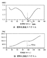
上述したように、生体組織切片13に超音波信号を照射すると、生体組織切片13の表面と背面からの反射波が干渉した干渉反射波信号Soが得られる。そこで、プレパラート12の表面からの参照反射波信号Srと生体組織切片13からの干渉反射波信号Soとをそれぞれフーリエ変換して、参照反射波信号Srと干渉反射波信号So(具体的には一次反射波信号Su1)と比較することで、規格化した強度スペクトルと同じく規格化した位相スペクトルを得ることができる。このスペクトル例を図18A,図18Bに示す。
As described above, when an ultrasonic signal is applied to the
そして、信号強度の極小点または極大点の周波数をfm、そのときの位相をφmとすると、生体組織切片13の表面と背面からの反射波は極小点では逆位相、極大点では同位相となっている。すなわち極小点においては生体組織切片13の表面からの反射波は背面からの反射波より(2n−1)πだけ進んでおり、{φm+(2n−1)π}となる(nは自然数)。生体組織切片13の厚さをd、水の音速をCoとすれば、
If the frequency of the signal intensity minimum point or maximum point is fm, and the phase at that time is φm, the reflected waves from the front and back surfaces of the
極大点においてはこの位相差が2nπとなっていることから、 Since this phase difference is 2nπ at the maximum point,
が成立している。一方、2dの距離を生体組織切片13内の音速Cで通過した反射波と、参照音速Coで通過した反射波の位相差がφmであるから、
Is established. On the other hand, the phase difference between the reflected wave that has passed through the distance of 2d at the sound velocity C in the
(9)式と(11)式を連立させて解くと、
d={φm+(2n−1)π}Co/4πfm ・・・(12)
のようにして生体組織切片13の厚さdを求めることができる。また、(10)式と(11)式を連立させて解くと、
Solving equations (9) and (11) simultaneously,
d = {φm + (2n−1) π} Co / 4πfm (12)
Thus, the thickness d of the
のように生体組織切片の音速Cが求まる。 Thus, the speed of sound C of the biological tissue slice is obtained.
一方、生体組織切片13の厚みdと音速Cを演算するときの周波数faは、図18Aに示す規格化強度スペクトルの最小値fm(この場合98MHz)を採用する。またその最小値fmでの位相φmは、図18Bの規格化位相スペクトル曲線より92degとなる。
On the other hand, the minimum value fm (98 MHz in this case) of the normalized intensity spectrum shown in FIG. 18A is adopted as the frequency fa when calculating the thickness d and the sound velocity C of the
厚みdと音速Cを演算するときには、fm=faとして代入するが、そのときの位相はリファレンス点となるプレパラート12上の参照点Poからの傾きによって生じたz軸方向(超音波出射方向)の距離差分Zpに相当する位相だけずれていることになる。したがって、この距離差分Zpに相当する位相分を補正する必要がある。距離差分Zpは(6)式によって算出できる。
When calculating the thickness d and the sound velocity C, fm = fa is substituted, but the phase at that time is in the z-axis direction (ultrasonic emission direction) generated by the inclination from the reference point Po on the
そこで、この距離差分Zpだけ補正した位相φmを以下のように演算する。 Therefore, the phase φm corrected by the distance difference Zp is calculated as follows.
このようにして算出した位相φmと、極小値での周波数fm(=fa)を、(12)式と(13)式に代入することで、距離差分Zpを補正した最終的な厚みdと音速Cを得ることができる。 By substituting the phase φm calculated in this way and the frequency fm (= fa) at the minimum value into the equations (12) and (13), the final thickness d and the sound velocity corrected for the distance difference Zp. C can be obtained.
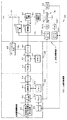
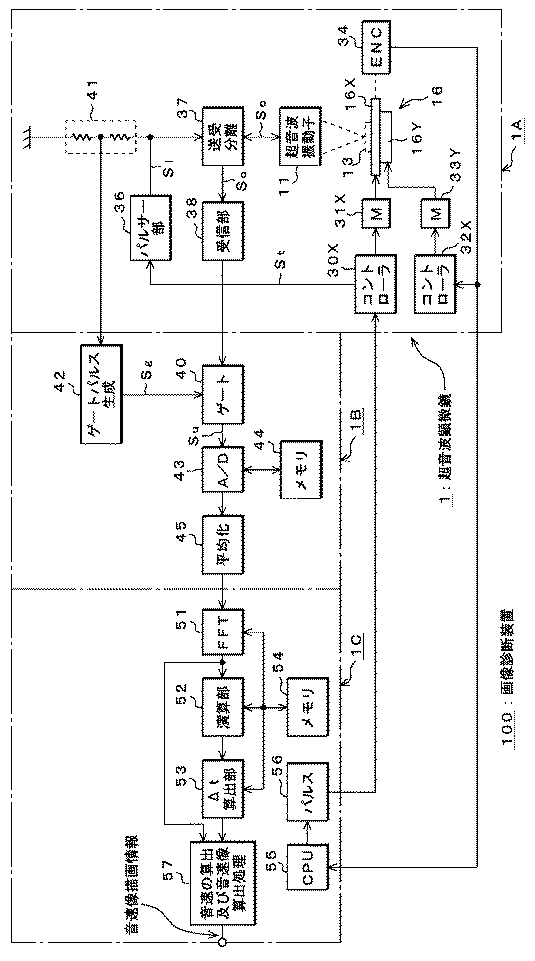
続いて、この発明に係る超音波顕微鏡を使用した画像診断装置100の一例を図1以下を参照して説明する。
Next, an example of an image
この画像診断装置100は大別して超音波顕微鏡1の本体部1Aと、第1の信号処理部1Bと第2の信号処理部1Cとで構成される。この画像診断装置100は、当然のことながら厚み測定装置としても機能する。相違する点は、厚み測定装置の場合には、後述するように音速像の算出処理部57が含まない点である。
The
したがってこの画像診断装置100は、超音波振動子11に加える励起パルスの間欠励起間隔の中で、集中的に複数個の励起パルスを短時間に励起する集中パルス励起機能を有したパルサー部36と、被測定物13を二次元走査する二次元走査手段16と、二次元走査手段16に対する駆動手段31X,33Yと、この駆動手段31X,33Yに供給される駆動パルスの生成手段56と、超音波振動子11より得られる反射波信号を集中パルス励起期間ごとに平均化する信号演算手段1Cと、平均化された反射波信号に基づいて被測定物13の音速の算出と、算出した音速に基づいて音速像を生成する手段57とで構成されていることになる。
Therefore, the
顕微鏡本体部1Aは、上述したように被測定物であるこの例では生体組織切片13を二次元的に動かすために二次元走査手段として使用されるX−Yステージ16が超音波振動子11と正対する。X−Yステージ16はそれぞれのステージ16X,16Yを駆動するモータ31X,33Yが設けられている。駆動モータ31X,33Yはステッピングモータやリニアモータを使用することができ、好ましくは高速かつ低振動のリニアモータが好適である。
In this example, which is the object to be measured as described above, the microscope main body 1A has an
ステッピングモータ、特にリニアモータを使用することで、Xステージ16Xを連続走査(連続送り)することが可能となり、そして、Yステージ16Yを間欠送りとなるように制御することで、X−Yステージ16の高速走査が可能になる。
By using a stepping motor, particularly a linear motor, the
駆動モータ31X,33Yにはそれぞれこれらに対する駆動信号を生成するためのコントローラ30X,32Yが設けられ、一方のコントローラ30Xには第2の信号処理部1Cで生成された駆動制御信号(パルス信号)が供給される。
The
この例ではXステージ16Xに関連してエンコーダ34が設けられ、このエンコーダ34によってXステージ16Xの走査位置が検出される。例えば、図13のようにプレパラート12を含めて300×300個の測定点(ピクセル)に分割したときには、1回のx方向における走査が300分割されることになるので、それぞれのピクセルの位置がこのエンコーダ34によって検出され、このエンコーダ出力に同期して駆動制御信号が生成される。
In this example, an
そのため、エンコーダ出力が第2の信号処理部1C内に設けられたCPU55に同期信号として供給されており、またCPU55にはパルス生成部56が関連され、したがってパルス生成部56ではエンコーダ出力に同期した駆動制御信号が生成される。詳細は割愛するも、このCPU55は装置全体の制御を司る制御部としても機能する。
Therefore, the encoder output is supplied as a synchronization signal to the
Xステージ16X用のコントローラ30Xからはさらに駆動制御信号に同期したトリガー信号Stが生成されて、これがパルサー部36に供給される。パルサー部36ではこのトリガー信号Stに同期したタイミングで励起パルスが生成される。
The
パルサー部36は超音波振動子11に対する励起パルスを生成するためのもので、この励起パルスは送受波分離部37を介して超音波振動子11に供給される。パルサー部36からの励起パルスSiは広帯域幅のパルス信号であって(図12参照)、この例では図11Aに示すように1サイクルの正弦波状をなすパルス信号が出力されるように構成されている。
The
パルサー部36は後述するように、トリガー信号Stによって間欠的に駆動されるが、この単位間欠周期の中で、さらに集中的に複数個の励起パルスが短時間に出力できるように構成されている。
As will be described later, the
超音波振動子11は送受波兼用の振動子が使用され、励起パルスによって励起されることで、ビーム状に絞られた超音波信号Siが出射される。同じ超音波振動子11で受波した反射波信号SrやSoのうち、生体組織切片13から得られる反射波信号Soは干渉波形である。これら反射波信号Sr,Soは送受波分離部37および受信部38を介して、信号演算部として機能する第1の信号処理部1Bに供給される。
As the
第1の信号処理部1Bはゲート回路40とゲートパルス生成回路42を有する。ゲートパルス生成回路42には励起パルスに同期したパルス信号が供給される。そのため、パルサー部36の出力段には抵抗分圧部41が設けられ、抵抗分圧部41で分圧された励起パルスSiがゲートパルス生成回路42に供給され、励起パルスSiより所定時間遅延したゲートパルスSgが生成される。
The first signal processing unit 1B includes a
一方、ゲート回路40には参照反射波信号Srと干渉反射波信号Soが供給され、上述したゲートパルスSgで干渉反射波信号Soのうち所望の信号部分のみがゲートされる。
On the other hand, the reference reflected wave signal Sr and the interference reflected wave signal So are supplied to the
ここで、干渉反射波信号Soは図11Cにも示すように超音波振動子11を励起する励起パルスSiに関連した反射波信号Si’とその反射波信号Suとが合成されたものである。超音波の反射波は超音波振動子11と生体組織切片13との間で反射が繰り返されることになるから、本来ではn次の反射波信号Suが多重信号として得られることになる。
Here, as shown in FIG. 11C, the interference reflected wave signal So is a combination of the reflected wave signal Si ′ related to the excitation pulse Si for exciting the
実施例では、そのうち最初に反射する反射波信号(一次反射波信号Su1という。)のみを抽出するため、励起パルスSiから所定時間だけ遅延したゲートパルスSgが使用されるものである。 In the embodiment, in order to extract only the reflected wave signal that is reflected first (referred to as the primary reflected wave signal Su1), the gate pulse Sg delayed by a predetermined time from the excitation pulse Si is used.
ゲートされた一次反射波信号Su1はA/D変換回路43に供給されてA/D変換処理されると共に、処理されたA/D変換出力がメモリ手段44に一時的に保存される。後述するように、超音波振動子11は所定周期で間欠的に励起されるが、この単位間欠周期の中で、さらに集中的に複数個の励起パルスが短時間に励起される。詳細は後述するとして、この例では7〜10回程度高速励起される。以下では8回高速励起した場合を示す。
The gated primary reflected wave signal Su1 is supplied to the A /
そして、それぞれがメモリ手段44に格納されると共に、8個目の一次反射波信号Su(8)を取得した後、後段の平均化回路45でこれら一次反射波信号Su1(1)、Su2(2)、・・・Su8(8)を用いて平均化される。このような平均化処理を施すのは、1つの一次反射波信号Su1だけでは充分なS/N(つまりC/N)が得られないためであり、S/Nを改善することが主目的である。
Each of them is stored in the memory means 44, and after the eighth primary reflected wave signal Su (8) is acquired, the primary reflected wave signals Su1 (1) and Su2 (2) are obtained by the averaging
また、上述したようにパルサー部38の出力段側に設けられた抵抗分圧部41で分圧された励起パルスSiを用いてゲートパルスSgを生成したのは、8回高速励起して8つの一次反射波信号Su1を得るときの、ゲートパルスSgのジッタを回避するためである。ゲートパルスSgにジッタがなければ、一次反射波信号Su1を平均化したときの同期ジッタ成分がゼロとなるため、安定した平均化出力を得ることができるからである。
In addition, as described above, the gate pulse Sg is generated using the excitation pulse Si divided by the resistance
なお、このような目的で使用できる高速処理可能なゲート機能付きA/Dボードとしては汎用の高速A/Dボード(例えば販売先が横河製作所である型番741025などのA/Dボード)を使用できる。 Note that a general-purpose high-speed A / D board (for example, an A / D board such as model number 741025 sold by Yokogawa Seisakusho) is used as an A / D board with a gate function capable of high-speed processing that can be used for such purposes. it can.
平均化処理された一次反射波信号Suは第2の信号処理部1Cに供給される。第2の信号処理部1Cでは、音速像を得るための前処理として、平面方程式のZの算出処理や係数a,b,cを算出するための補正値算出処理が行われる。その他に音速の算出処理および音速像の生成処理が行われる。 The averaged primary reflected wave signal Su is supplied to the second signal processing unit 1C. In the second signal processing unit 1C, as preprocessing for obtaining a sound velocity image, Z calculation processing of a plane equation and correction value calculation processing for calculating coefficients a, b, and c are performed. In addition, sound speed calculation processing and sound speed image generation processing are performed.
そのため、この第2の信号処理部1Cでは、一次反射波信号Su1が供給される高速フーリエ変換処理部51、フーリエ変換出力を演算処理する演算部52、演算処理された規格化スペクトルから時間差Δtを算出するΔt算出部53およびこれらの処理を行うときのワーキング用メモリ手段54などが設けられる。
Therefore, in the second signal processing unit 1C, the fast Fourier
さらに、時間差Δtのデータやフーリエ変換出力がそれぞれ供給される音速の算出と音速像生成処理部57が設けられる。この音速算出および音速像生成処理部57は画像描画部として機能することになる。時間差Δtは係数a,b,cを算出するときに供給されるデータであり、フーリエ変換出力は通常の音速像を生成するときに供給されるデータである。
Further, a sound speed calculation and sound speed image
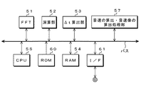
そして、CPU55内のROM60(図2参照)にストアされているz値算出のための処理プログラムや音速算出用処理プログラムさらには音速像算出用処理プログラムを実行することによって、上述したz値算出処理などが行われることになる。
Then, by executing a processing program for calculating the z value, a processing program for calculating the sound speed, and a processing program for calculating the sound speed stored in the ROM 60 (see FIG. 2) in the
このCPU55にはさらにコントローラ30Xに供給するためのパルス生成部56が関連され、CPU55からの同期パルスに同期してパルス生成部56が駆動される。CPU55にはさらに顕微鏡本体部1Aに設けられたエンコーダ34のエンコーダ出力が供給される。このエンコーダ出力に同期してCPU55から同期パルスが出力される。
The
したがって最終的にはエンコーダ34のエンコーダ出力に同期してトリガー信号Stが生成されるため、生体組織切片13の各ピクセルに同期してパルサー部36が励起されるので、確実にそれぞれのピクセルごとに超音波信号を照射できるようになる。
Therefore, since the trigger signal St is finally generated in synchronization with the encoder output of the
第2の信号処理部1Cの各部構成の関係は、コンピュータを中心にすると、図2のようにも書き替えることができる。上述したワーキング用のメモリ手段54は図2のRAMが使用されることになる。インタフェース61を介して一次反射波信号(デジタル信号)Su1が取り込まれる。
The relationship between the components of the second signal processing unit 1C can be rewritten as shown in FIG. The working memory means 54 uses the RAM shown in FIG. The primary reflected wave signal (digital signal) Su1 is taken in via the
画像描画部としても機能する音速像の算出処理部57では、等音速線によって描画されることで、生体組織切片13の組織がミクロン単位で描画される。同一音速同士をつなぎ合わせることで得られる等音速線をモニタ(図示せず)に描画することで生体組織の可視像(音速像)が得られる。この音速像から生体組織を観察し、診断できる。
In the sonic image
等音速線で囲まれる領域を同じ色で表示することでカラー表示が可能になり、これによって変質した生体組織を明確に識別できるようになる。表示色にグラデーションをかけることで組織の境界遷移がスムーズになる。もちろん、一次反射波信号Su1の減衰度(強度)を基準にして描画すると生体像として減衰像が得られる。 By displaying the area surrounded by the isosonic line in the same color, color display becomes possible, and this makes it possible to clearly identify the altered biological tissue. By applying gradation to the display color, the boundary transition of the organization becomes smooth. Of course, when drawing is performed based on the attenuation (intensity) of the primary reflected wave signal Su1, an attenuation image is obtained as a living body image.
続いて、図1に示した画像診断装置100の動作を図3以下を参照して説明する。
図3は一次反射波信号Su1のS/Nの説明図である。上述したように生体組織切片13を高速で二次元走査して最終的には計測を開始してから、5分、就中2分以下で音速像を描画できるようにするには、x方向への走査を高速連続走査して1ラインの走査時間を高速化する必要がある。
Next, the operation of the
FIG. 3 is an explanatory diagram of S / N of the primary reflected wave signal Su1. As described above, in order to be able to draw a sound velocity image within 5 minutes, especially 2 minutes or less after the
この例では、1ピクセルに対する計測時間が80μsec程度となるからトリガー信号Stの間隔も80μsecとなる(図3A)。 In this example, since the measurement time for one pixel is about 80 μsec, the interval of the trigger signal St is also 80 μsec (FIG. 3A).
トリガー信号Stに同期して励起パルスSiが得られる(図3B)。そしてその反射波は図3Cのようになる。励起パルスSiに関連した反射波信号Si’に対して大凡2μsec遅れて一次反射波信号Su1が、さらに2μsec遅れて二次反射波信号Su2が得られる。反射波信号Soの幅は100nsec程度である。 An excitation pulse Si is obtained in synchronization with the trigger signal St (FIG. 3B). The reflected wave is as shown in FIG. 3C. The primary reflected wave signal Su1 is obtained with a delay of about 2 μsec with respect to the reflected wave signal Si ′ related to the excitation pulse Si, and the secondary reflected wave signal Su2 is obtained with a delay of 2 μsec. The width of the reflected wave signal So is about 100 nsec.
最も単純な信号処理は、図3DのゲートパルスSgを用いて一次反射波信号Su1を抽出する処理であるが、これでは充分なS/Nが得られない。
S/Nを改善するには、複数回超音波振動子11を励起して同じ信号を得、これを平均化すればよい。しかし、そうするためには同じ走査位置で複数回の励起処理を行わなければならないので、次のピクセルに対する計測開始までに複数倍の時間がかかってしまう。これでは、高速画像処理を実現できない。
The simplest signal processing is processing for extracting the primary reflected wave signal Su1 using the gate pulse Sg of FIG. 3D, but this does not provide sufficient S / N.
In order to improve the S / N, the
そこで、超音波振動子11を間欠的に励起する時間間隔を保ったまま、さらにこの間欠励起時間内で集中的に複数個の励起パルスを短時間に励起することで、短時間に複数個の一次反射波信号を取得し、その平均化した信号を反射波信号として用いるようにする。具体例を図4を参照して説明する。
Therefore, while maintaining a time interval for intermittently exciting the
上述したように励起パルスSiに対する反射波信号Si’から一次反射波信号Su1が得られるまでの時間は大凡2μsecであり、この一次反射波信号Su1が最もS/Nがよく、二次以降の反射波信号Su2、・・・は超音波振動子11と生体組織切片13との間の多重反射信号であるためS/Nが悪い。
As described above, the time until the primary reflected wave signal Su1 is obtained from the reflected wave signal Si ′ with respect to the excitation pulse Si is about 2 μsec, and this primary reflected wave signal Su1 has the best S / N, and the secondary and subsequent reflections. Since the wave signal Su2,... Is a multiple reflection signal between the
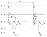
したがって、図4Aのように高速画像処理を実現するため間欠励起時間は図3の場合と同じにする。次に、使用する反射波信号としては一次反射波信号Su1のみとする。この反射波信号の取捨を行うため、ほぼ2μsec間隔で複数回(2回以上)、好ましくは7〜10回、例えば8回に亘り連続的に超音波振動子11を励起する。すなわち、図4Aに示すようにトリガー信号Stに対して、パルサー部36では図4Bに示すような2μsec間隔の励起パルスが8個連続的に生成される。
Therefore, the intermittent excitation time is made the same as in FIG. 3 in order to realize high-speed image processing as shown in FIG. 4A. Next, the primary reflected wave signal Su1 is the only reflected wave signal to be used. In order to dispose of the reflected wave signal, the
この2μsec間隔の励起パルスSiで超音波振動子11が励起される。その結果、図4Cに示すような反射波信号が得られる。
The
その一方で、励起パルスSiに同期したゲートパルスSg(図4D)が生成される。この連続的なゲートパルスSgで一次反射波信号Su1のみをゲートすれば、8個の一次反射波信号Su1が得られる(図4E)。図4Eは便宜的に並べて図示したものである。実際にはこのような時系列で信号が並ぶものではないことは明らかである。 On the other hand, a gate pulse Sg (FIG. 4D) synchronized with the excitation pulse Si is generated. If only the primary reflected wave signal Su1 is gated by this continuous gate pulse Sg, eight primary reflected wave signals Su1 are obtained (FIG. 4E). FIG. 4E is shown side by side for convenience. It is clear that the signals are not actually arranged in such a time series.
これら8個の一次反射波信号Su1(1)〜Su8(8)を平均化処理して、最終的な一次反射波信号Suが生成される(図4F)。この処理によって一次反射波信号SuのS/Nが改善されると共に、高速画像処理が可能になる。 These eight primary reflected wave signals Su1 (1) to Su8 (8) are averaged to generate a final primary reflected wave signal Su (FIG. 4F). This process improves the S / N of the primary reflected wave signal Su and enables high-speed image processing.
続いて、この発明に係る画像診断方法を実現する処理例を図5および図6のフローチャートを参照して説明する。 Next, a processing example for realizing the image diagnostic method according to the present invention will be described with reference to the flowcharts of FIGS.
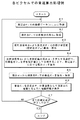
図5は、平面方程式における係数a,b,cを算出するための処理例を示すフローチャートであって、この算出処理プログラムは音速像を生成するための生成処理プログラムの一部としてプログラムされている場合と、単独にサブルーチンとしてプログラムされている場合がある。 FIG. 5 is a flowchart showing a processing example for calculating the coefficients a, b, and c in the plane equation, and this calculation processing program is programmed as a part of the generation processing program for generating the sound velocity image. Sometimes it is programmed as a subroutine alone.
以下はサブルーチンとしてプログラムしたときの処理例であり、この算出プログラムが起動されると、まずXYテーブル16を走査してプレパラート12上における任意の測定ポイント(測定点)Pi(i=0,1,2であって、Po,P1,P2)の座標データ(xi,yi){i=0,1,2であって、(x0,y0)、(x1,y1)、(x2,y2)}を取得する(ステップ71)。
The following is an example of processing when programmed as a subroutine. When this calculation program is started, first, the XY table 16 is scanned and any measurement point (measurement point) Pi (i = 0, 1, 1) on the
次に、これら測定ポイントPiでの反射波信号Sri(i=0,1,2であって、Sro,Sr1,Sr2)を取得すると共に(ステップ72)、得られた反射波信号Sriをそれぞれ高速フーリエ変換してフーリエ変換出力Fiを求める(ステップ73)。 Next, the reflected wave signals Sri (i = 0, 1, 2 and Sro, Sr1, Sr2) at these measurement points Pi are acquired (step 72), and the obtained reflected wave signals Sri are respectively transmitted at high speed. Fourier transform is performed to obtain a Fourier transform output Fi (step 73).
続いて、これらフーリエ変換出力Fiより参照フーリエ変換出力Froとの比(Fr1/FroおよびFr2/Fro)を演算して規格化スペクトルを求める(ステップ74)。 Subsequently, a normalized spectrum is obtained by calculating a ratio (Fr1 / Fro and Fr2 / Fro) with the reference Fourier transform output Fro from these Fourier transform outputs Fi (step 74).
このようにして求めた規格化スペクトルの周波数成分fと位相成分φから、
φ/2πfでの時間差Δti(i=1,2)を算出する(ステップ75)。
From the frequency component f and the phase component φ of the normalized spectrum thus obtained,
A time difference Δti (i = 1, 2) at φ / 2πf is calculated (step 75).
測定ポイントPi(i=1,2)における参照点Poからの時間差Δt1,Δt2と既知の音速Co(この例では水の音速)から、測定ポイントP1,P2での平面方程式Zi(i=1,2であって、Z1,Z2)を求める(ステップ76)。この平面方程式Ziが参照点Poに対する測定ポイントP1及びP2でのz値(傾き量)となる。 From the time differences Δt1, Δt2 from the reference point Po at the measurement point Pi (i = 1, 2) and the known sound velocity Co (the sound velocity of water in this example), the plane equation Zi (i = 1, 1) at the measurement points P1, P2. 2 and Z1 and Z2) are obtained (step 76). This plane equation Zi becomes the z value (inclination amount) at the measurement points P1 and P2 with respect to the reference point Po.
このような処理を経て算出した3つの平面方程式Zo,Z1,Z2より係数a,b,cが算出され、算出された係数a,b,cがメモリ手段54に保存される(ステップ77)。したがって、これら生体組織切片13の全ての測定点Pp(xp,yp)における平面方程式Zp、つまり参照点Poを基準にした測定ポイントPpでのz値Zpを算出できることになる。なお、この係数算出処理は音速像生成の前処理として被測定物である生体組織を観察する都度実行される。
Coefficients a, b and c are calculated from the three plane equations Zo, Z1 and Z2 calculated through such processing, and the calculated coefficients a, b and c are stored in the memory means 54 (step 77). Therefore, it is possible to calculate the plane equation Zp at all the measurement points Pp (xp, yp) of these
図6は傾き補正を含めた音速算出例を示すフローチャートであって、係数a,b,cはすでに保存されているものとする。
音速像生成処理プログラムが起動されると、CPU55からの指示に基づいてX−Yステージ16が駆動されてx方向への走査が開始されると共に、エンコーダ34からのエンコーダ出力に同期して駆動制御信号がコントローラ30Xに供給される。
FIG. 6 is a flowchart showing an example of sound speed calculation including inclination correction, and it is assumed that the coefficients a, b, and c are already stored.
When the sonic image generation processing program is started, the
この駆動制御信号に同期してトリガー信号Stがパルサー部36に供給され、超音波振動子11が励起される。この一連の処理によって得られたx方向における走査線上の測定点(ピクセル)Piの座標(xi,yi)(i=1〜300)を取得すると共に(ステップ81)、測定点Piでの反射波信号Soiを取得する(ステップ82)。反射波信号Soiとしては、ほぼ同一測定点Piからの得られた複数個、この例では8個の一次反射波信号Su1を平均した信号が利用される。
In synchronization with this drive control signal, a trigger signal St is supplied to the
続いて、この反射波信号Soiより測定点Piでの平面方程式、換言すれば測定点Piでのz値(傾き量)Zpが算出されて、これが保存される(ステップ83)。 Subsequently, a plane equation at the measurement point Pi, in other words, a z value (tilt amount) Zp at the measurement point Pi is calculated from the reflected wave signal Soi, and stored (step 83).
その後、反射波信号Soiと、参照すべき反射波信号Srとの時間差、反射波信号Soiの強度、位相差などから測定点Piでの生体組織切片の厚みdiが算出される(ステップ84)。この厚み算出過程でz値Zpが参照される。つまり、このステップ84でプレパラート12の傾きを含めた状態での厚みdiが得られ、傾きによる影響を除去した厚みdiとなる。
Thereafter, the thickness di of the biological tissue section at the measurement point Pi is calculated from the time difference between the reflected wave signal Soi and the reflected wave signal Sr to be referred to, the intensity of the reflected wave signal Soi, the phase difference, and the like (step 84). The z value Zp is referred to in this thickness calculation process. That is, in step 84, the thickness di including the inclination of the
次に、算出された厚みdiから測定点Piでの音速Ciが算出され、その値が描画プレーン(フレーム)として機能するメモリ手段54に保存される(ステップ85)。そしてこの音速Ciが等音速線のデータとして画面上に描画されると共に、描画情報としてさらにメモリ手段54の別のエリアに保存される(ステップ86)。 Next, the sound velocity Ci at the measurement point Pi is calculated from the calculated thickness di, and the value is stored in the memory means 54 functioning as a drawing plane (frame) (step 85). The sonic speed Ci is drawn on the screen as isosonic line data, and is further saved as drawing information in another area of the memory means 54 (step 86).
このような音速算出処理が全てのピクセル(例えば300×300ピクセル)に対して実行されるので(ステップ87)、全てのピクセルに対し音速データを取得することで、生体組織の等音速線を描画できる。等音速線をカラー表示して区別することで、カラー音速線が得られる。等音速線の描画によって生体組織の音速像が得られる。また各測定点Piでの反射波信号Soiより反射強度(減衰量)を得ることで、生体組織の減衰像を得ることができる。 Since such a sound speed calculation process is executed for all pixels (for example, 300 × 300 pixels) (step 87), by obtaining sound speed data for all pixels, an isosonic line of biological tissue is drawn. it can. A color sound speed line can be obtained by distinguishing the isosonic speed line by color display. A sonic image of a living tissue can be obtained by drawing an isosonic line. Further, an attenuation image of the biological tissue can be obtained by obtaining the reflection intensity (attenuation amount) from the reflected wave signal Soi at each measurement point Pi.
上述した実施例では、一次反射波信号Su1を平均化する回数を8回に選定したが、この回数設定は任意である。励起パルスSiの間欠励起周期として実施例では80μsecを例示したが、これも一例に過ぎない。80μsecよりも短周期による間欠励起が可能であるならば、生体組織切片に対する画素数(ピクセル数)を増やしても音速像の生成時間が増えることはないし、増加した分、解像度が増すので、より正確で、微視的な病変部を観察することが可能になる。 In the above-described embodiment, the number of times of averaging the primary reflected wave signal Su1 is selected as eight times, but this number setting is arbitrary. In the embodiment, 80 μsec is exemplified as the intermittent excitation cycle of the excitation pulse Si, but this is also merely an example. If intermittent excitation with a period shorter than 80 μsec is possible, the generation time of the sound velocity image does not increase even if the number of pixels (pixel number) for the biological tissue section is increased, and the resolution increases by the increased amount. An accurate and microscopic lesion can be observed.
もちろん、平均化回数を切り替えられるように構成することもできる。例えば、2回から10回程度までをそれぞれ段階的に切り替えて測定することもできる。その場合には、CPU55からの指令に基づいてパルサー部36に対し連続間欠発振回数が指定される。
Of course, it is also possible to change the averaging count. For example, the measurement can be performed by switching from 2 to 10 times step by step. In that case, the number of continuous intermittent oscillations is designated for the
上述した実施例では、被測定物として生体組織切片を用いたときの音速測定と、生体組織の音速像を得る場合にそれぞれ適用したが、被測定物の音速測定及び音速像の生成としては生体組織に限らず、種々の被測定物が測定対象となり得ることは明らかである。その他は実施例1と同じである。 In the above-described embodiments, the present invention is applied to the measurement of sound velocity when a biological tissue slice is used as the object to be measured and the case of obtaining the sound velocity image of the biological tissue. It is clear that various objects to be measured are not limited to tissues and can be measured. Others are the same as in the first embodiment.
この発明は、超音波顕微鏡を使用して試料の音速を測定する音速測定装置、生体組織、その他の被測定物の表面状態を観察したり診断したりする画像診断装置に適用できる。 The present invention can be applied to a sound velocity measuring device that measures the sound velocity of a sample using an ultrasonic microscope, an image diagnostic device that observes and diagnoses the surface state of a biological tissue and other objects to be measured.
1・・・超音波顕微鏡
11・・・超音波振動子
12・・・プレパラート
13・・・被測定物(生体組織切片)
16・・・X−Yステージ
16X・・・Xステージ
16Y・・・Yステージ
17・・・媒質(水)
21・・・音速像
1A・・・顕微鏡本体部
1B・・・第1の信号処理部
1C・・・第2の信号処理部
36・・・パルサー部
40・・・ゲート回路
42・・・ゲートパルス生成回路
45・・・平均化回路
51・・・FFT処理部
55・・・CPU
57・・・音速像生成処理部
DESCRIPTION OF
16 ...
21 ... sound velocity image 1A ... microscope main body 1B ... first signal processing unit 1C ... second
57 ... Sound velocity image generation processing unit
Claims (17)
励起パルスで上記超音波振動子を間欠的に励起すると共に、この間欠的な励起パルス間隔の中で集中的に複数個の励起パルスを短時間に励起する集中パルス励起ステップと、
この集中パルス励起期間中に得られる上記励起パルスからの反射波信号を平均化するステップと、
平均化した反射波信号に基づいて、上記被測定物の音速を算出するステップ
とを有することを特徴とする超音波顕微鏡を使用した音速測定方法。 A sound velocity measurement method using a pulse excitation type ultrasonic microscope that measures the sound velocity of an object to be measured by pulse exciting an ultrasonic transducer,
A concentration pulse excitation step of exciting the ultrasonic transducer intermittently with an excitation pulse and simultaneously exciting a plurality of excitation pulses in a short time in the intermittent excitation pulse interval;
Averaging the reflected wave signal from the excitation pulse obtained during the lumped pulse excitation period;
And a step of calculating a sound velocity of the object to be measured based on the averaged reflected wave signal.
ことを特徴とする請求項1記載の超音波顕微鏡を使用した音速測定方法。 2. The sound speed measurement method using an ultrasonic microscope according to claim 1, wherein the concentrated pulse excitation is performed in synchronization with a horizontal scan of the object to be measured.
上記励起パルスに関連した信号を除去した反射波信号を用いて平均化処理が行われる
ことを特徴とする請求項1記載の超音波顕微鏡を使用した音速測定方法。 A step for removing a signal related to an excitation pulse contained in the reflected wave signal;
The sound speed measurement method using an ultrasonic microscope according to claim 1, wherein the averaging process is performed using a reflected wave signal from which a signal related to the excitation pulse is removed.
ことを特徴とする請求項4記載の超音波顕微鏡を使用した音速測定方法。 5. The sound speed measuring method using an ultrasonic microscope according to claim 4, wherein the removing step is a step of extracting a primary reflected wave signal from the reflected wave signal.
ことを特徴とする請求項4記載の超音波顕微鏡を使用した音速測定方法。 An extraction gate pulse for extracting a primary reflected wave signal from the reflected wave signal is generated in synchronization with an excitation pulse applied to the ultrasonic transducer during the concentrated pulse excitation period. A sound speed measuring method using the ultrasonic microscope according to claim 4.
ことを特徴とする請求項5記載の超音波顕微鏡を使用した音速測定方法。 6. The sound speed measuring method using an ultrasonic microscope according to claim 5, wherein the gate pulse is generated in synchronization with the excitation pulse output from a pulsar unit that drives the ultrasonic transducer.
ことを特徴とする請求項1記載の超音波顕微鏡を使用した音速測定画方法。 The method according to claim 1, wherein the excitation pulse is a broadband pulse signal.
上記超音波振動子に加える励起パルスの間欠励起間隔の中で、集中的に複数個の励起パルスを短時間に励起する集中パルス励起機能を有したパルサー部と、
上記被測定物を二次元走査する二次元走査手段と、
当該二次元走査手段に対する駆動手段と、
この駆動手段に供給される駆動パルスの生成手段と、
上記超音波振動子より得られる反射波信号を上記集中パルス励起期間ごとに平均化する信号演算手段とで構成され、
上記駆動パルス生成手段から上記パルサー部にパルス励起用のトリガー信号が供給されると共に、上記信号演算手段での平均化された信号が反射波信号として利用される
ことを特徴とする超音波顕微鏡を使用した音速測定装置。 A sound velocity measuring device using a pulse excitation type ultrasonic microscope that measures the sound velocity of an object to be measured by pulse exciting an ultrasonic transducer,
In the intermittent excitation interval of the excitation pulse applied to the ultrasonic vibrator, a pulsar unit having a concentrated pulse excitation function for exciting a plurality of excitation pulses in a short time in a concentrated manner;
Two-dimensional scanning means for two-dimensionally scanning the object to be measured;
Driving means for the two-dimensional scanning means;
Drive pulse generation means to be supplied to the drive means;
It is composed of signal calculation means for averaging the reflected wave signal obtained from the ultrasonic transducer for each concentrated pulse excitation period,
An ultrasonic microscope characterized in that a trigger signal for pulse excitation is supplied from the drive pulse generating means to the pulsar unit, and an averaged signal from the signal calculating means is used as a reflected wave signal. Used sound speed measurement device.
ことを特徴とする請求項8記載の超音波顕微鏡を使用した音速測定装置。 9. The sound speed measuring apparatus using an ultrasonic microscope according to claim 8, wherein the pulsar unit is driven in synchronization with the two-dimensional scanning by using a trigger signal from the driving pulse generating means.
ことを特徴とする請求項8記載の超音波顕微鏡を使用した音速測定装置。 9. The super-wave circuit according to claim 8, wherein the signal calculation means is provided with a gate circuit, and the reflected wave signal is gated by a gate pulse generated based on an excitation pulse output from the pulsar unit. Sound velocity measuring device using an acoustic microscope.
ことを特徴とする請求項10記載の超音波顕微鏡を使用した音速測定装置。 11. The sound speed measuring apparatus using an ultrasonic microscope according to claim 10, wherein a primary reflected wave signal is gated among the reflected wave signals.
励起パルスで上記超音波振動子を間欠的に励起すると共に、この間欠的な励起パルス間隔の中で集中的に複数個の励起パルスを短時間に励起する集中パルス励起ステップと、
この集中パルス励起期間中に得られる上記励起パルスからの反射波信号を平均化するステップと、
平均化した反射波信号に基づいて、上記被測定物の厚みを算出するステップと、
算出された上記厚みを用いて、上記被測定物の音速像を生成するための音速を算出するステップとを
有することを特徴とする超音波顕微鏡を使用した画像診断方法。 An image diagnostic method using a pulse excitation type ultrasonic microscope that acquires a property of an object to be measured as a sound velocity image by pulse exciting an ultrasonic transducer,
A concentration pulse excitation step of exciting the ultrasonic transducer intermittently with an excitation pulse and simultaneously exciting a plurality of excitation pulses in a short time in the intermittent excitation pulse interval;
Averaging the reflected wave signal from the excitation pulse obtained during the lumped pulse excitation period;
Calculating the thickness of the object to be measured based on the averaged reflected wave signal;
And a step of calculating a sound speed for generating a sound speed image of the object to be measured using the calculated thickness. An image diagnostic method using an ultrasonic microscope, comprising:
上記励起パルスに関連した信号を除去した一次反射波信号を用いて平均化処理が行われる
ことを特徴とする請求項12記載の超音波顕微鏡を使用した画像診断方法。 A step for removing a signal related to an excitation pulse contained in the reflected wave signal;
13. The diagnostic imaging method using an ultrasonic microscope according to claim 12, wherein an averaging process is performed using a primary reflected wave signal from which a signal related to the excitation pulse is removed.
ことを特徴とする請求項13記載の超音波顕微鏡を使用した画像診断方法。 An extraction gate pulse for extracting a primary reflected wave signal from the reflected wave signal is generated in synchronization with an excitation pulse applied to the ultrasonic transducer during the concentrated pulse excitation period. An image diagnostic method using the ultrasonic microscope according to claim 13.
ことを特徴とする請求項14記載の超音波顕微鏡を使用した画像診断方法。 15. The diagnostic imaging method using an ultrasonic microscope according to claim 14, wherein the gate pulse is generated in synchronization with the excitation pulse output from a pulsar unit that drives the ultrasonic transducer.
上記超音波振動子に加える励起パルスの間欠励起間隔の中で、集中的に複数個の励起パルスを短時間に励起する集中パルス励起機能を有したパルサー部と、
上記被測定物を二次元走査する二次元走査手段と、
当該二次元走査手段に対する駆動手段と、
この駆動手段に供給される駆動パルスの生成手段と、
上記超音波振動子より得られる反射波信号を上記集中パルス励起期間ごとに平均化する信号演算手段と、
上記信号演算手段での平均化された反射波信号に基づいて上記被測定物の音速の算出と、算出した音速に基づいて音速像を生成する手段とで構成された
ことを特徴とする超音波顕微鏡を使用した画像診断装置。 An image diagnostic apparatus using a pulse excitation type ultrasonic microscope that acquires a property of an object to be measured as a sound velocity image by pulse exciting an ultrasonic transducer,
In the intermittent excitation interval of the excitation pulse applied to the ultrasonic vibrator, a pulsar unit having a concentrated pulse excitation function for exciting a plurality of excitation pulses in a short time in a concentrated manner;
Two-dimensional scanning means for two-dimensionally scanning the object to be measured;
Driving means for the two-dimensional scanning means;
Drive pulse generation means to be supplied to the drive means;
A signal calculating means for averaging the reflected wave signal obtained from the ultrasonic transducer for each of the concentrated pulse excitation periods;
An ultrasonic wave comprising: calculation of the sound speed of the object to be measured based on the averaged reflected wave signal in the signal calculating means; and means for generating a sound speed image based on the calculated sound speed Diagnostic imaging device using a microscope.
ことを特徴とする請求項16記載の超音波顕微鏡を使用した画像診断装置。
The signal calculation means is provided with a gate circuit, and a primary reflected wave signal of the reflected wave signal is gated by a gate pulse generated based on an excitation pulse output from the pulsar unit. An image diagnostic apparatus using the ultrasonic microscope according to claim 16.
Priority Applications (1)
| Application Number | Priority Date | Filing Date | Title |
|---|---|---|---|
| JP2004105214A JP4521585B2 (en) | 2004-03-31 | 2004-03-31 | Sonic velocity measuring method using ultrasonic microscope, sonic velocity measuring device, sonic velocity image acquiring method, and diagnostic imaging device |
Applications Claiming Priority (1)
| Application Number | Priority Date | Filing Date | Title |
|---|---|---|---|
| JP2004105214A JP4521585B2 (en) | 2004-03-31 | 2004-03-31 | Sonic velocity measuring method using ultrasonic microscope, sonic velocity measuring device, sonic velocity image acquiring method, and diagnostic imaging device |
Publications (2)
| Publication Number | Publication Date |
|---|---|
| JP2005291828A true JP2005291828A (en) | 2005-10-20 |
| JP4521585B2 JP4521585B2 (en) | 2010-08-11 |
Family
ID=35324929
Family Applications (1)
| Application Number | Title | Priority Date | Filing Date |
|---|---|---|---|
| JP2004105214A Expired - Fee Related JP4521585B2 (en) | 2004-03-31 | 2004-03-31 | Sonic velocity measuring method using ultrasonic microscope, sonic velocity measuring device, sonic velocity image acquiring method, and diagnostic imaging device |
Country Status (1)
| Country | Link |
|---|---|
| JP (1) | JP4521585B2 (en) |
Cited By (4)
| Publication number | Priority date | Publication date | Assignee | Title |
|---|---|---|---|---|
| JP2007171052A (en) * | 2005-12-22 | 2007-07-05 | Honda Electronic Co Ltd | Sonic velocity measuring method, sonic velocity measuring apparatus, and ultrasonic image inspection apparatus |
| JP2010104816A (en) * | 2008-06-18 | 2010-05-13 | Canon Inc | Photoacoustic imaging apparatus |
| JP2012251835A (en) * | 2011-06-01 | 2012-12-20 | Toshiba Corp | Valve diagnostic device and valve diagnostic method |
| US8920321B2 (en) | 2008-06-18 | 2014-12-30 | Canon Kabushiki Kaisha | Photoacoustic imaging apparatus |
Citations (5)
| Publication number | Priority date | Publication date | Assignee | Title |
|---|---|---|---|---|
| JPS61259168A (en) * | 1985-05-14 | 1986-11-17 | Olympus Optical Co Ltd | Gate timing change-over apparatus of ultrasonic microscope |
| JPH03262909A (en) * | 1990-03-13 | 1991-11-22 | Olympus Optical Co Ltd | Ultrasonic measuring instrument |
| JP2624749B2 (en) * | 1988-03-04 | 1997-06-25 | 日立建機株式会社 | Ultrasonic flaw detector |
| JP2002014083A (en) * | 2000-04-28 | 2002-01-18 | Nkk Corp | Method and apparatus for determining solidification state of cast slab and method for producing continuous cast slab |
| JP2003050117A (en) * | 2001-08-08 | 2003-02-21 | Olympus Optical Co Ltd | Thickness measuring method and thickness measuring device |
-
2004
- 2004-03-31 JP JP2004105214A patent/JP4521585B2/en not_active Expired - Fee Related
Patent Citations (5)
| Publication number | Priority date | Publication date | Assignee | Title |
|---|---|---|---|---|
| JPS61259168A (en) * | 1985-05-14 | 1986-11-17 | Olympus Optical Co Ltd | Gate timing change-over apparatus of ultrasonic microscope |
| JP2624749B2 (en) * | 1988-03-04 | 1997-06-25 | 日立建機株式会社 | Ultrasonic flaw detector |
| JPH03262909A (en) * | 1990-03-13 | 1991-11-22 | Olympus Optical Co Ltd | Ultrasonic measuring instrument |
| JP2002014083A (en) * | 2000-04-28 | 2002-01-18 | Nkk Corp | Method and apparatus for determining solidification state of cast slab and method for producing continuous cast slab |
| JP2003050117A (en) * | 2001-08-08 | 2003-02-21 | Olympus Optical Co Ltd | Thickness measuring method and thickness measuring device |
Cited By (4)
| Publication number | Priority date | Publication date | Assignee | Title |
|---|---|---|---|---|
| JP2007171052A (en) * | 2005-12-22 | 2007-07-05 | Honda Electronic Co Ltd | Sonic velocity measuring method, sonic velocity measuring apparatus, and ultrasonic image inspection apparatus |
| JP2010104816A (en) * | 2008-06-18 | 2010-05-13 | Canon Inc | Photoacoustic imaging apparatus |
| US8920321B2 (en) | 2008-06-18 | 2014-12-30 | Canon Kabushiki Kaisha | Photoacoustic imaging apparatus |
| JP2012251835A (en) * | 2011-06-01 | 2012-12-20 | Toshiba Corp | Valve diagnostic device and valve diagnostic method |
Also Published As
| Publication number | Publication date |
|---|---|
| JP4521585B2 (en) | 2010-08-11 |
Similar Documents
| Publication | Publication Date | Title |
|---|---|---|
| US6336899B1 (en) | Ultrasonic diagnosis apparatus | |
| JP5230589B2 (en) | Ultrasonic device, ultrasonic imaging program, and ultrasonic imaging method | |
| CN101797165B (en) | Ultrasonic diagnostic apparatus and controlling method of ultrasonic diagnostic apparatus | |
| EP2881041A1 (en) | Apparatus and method for ultrasonic diagnosis | |
| CN103025248B (en) | Image information acquiring apparatus and image information acquiring method | |
| KR20140020486A (en) | Method and apparatus for analyzing elastography of tissue using ultrasound | |
| JP2015065975A (en) | Subject information acquisition apparatus and control method thereof | |
| JP6108499B2 (en) | Method for imaging specular object and target anatomy in tissue using ultrasound and ultrasound imaging apparatus | |
| CN1293847C (en) | Ultrasonic diagnostic device and ultrasonic imaging method | |
| CN110151270B (en) | Vibration puncture device, frequency adjustment method and ultrasonic imaging system | |
| JP4654335B2 (en) | Ultrasonic image inspection method, ultrasonic image inspection apparatus | |
| JP4958475B2 (en) | Ultrasonic device | |
| JP2005319199A (en) | Ultrasonic diagnostic equipment | |
| JP7052530B2 (en) | Ultrasonic diagnostic equipment and ultrasonic signal processing method | |
| JP4521585B2 (en) | Sonic velocity measuring method using ultrasonic microscope, sonic velocity measuring device, sonic velocity image acquiring method, and diagnostic imaging device | |
| JP4521584B2 (en) | Sonic velocity measuring method using ultrasonic microscope, sonic velocity measuring device, sonic velocity image acquiring method using ultrasonic microscope, and diagnostic imaging device thereof | |
| JP2020138017A (en) | Ultrasonic diagnostic equipment | |
| JP5326132B2 (en) | Acoustic impedance measuring apparatus and acoustic impedance measuring method | |
| JP4830100B2 (en) | Inspected object measuring method and inspected object measuring apparatus | |
| JP4996141B2 (en) | Ultrasonic diagnostic equipment | |
| JP4613269B2 (en) | Sonic velocity measuring method and sonic velocity measuring device | |
| US20180149464A1 (en) | Automated optical coherence tomography scanning | |
| CN210447159U (en) | Vibration puncture device and ultrasonic imaging system | |
| JP4830099B2 (en) | Sonic velocity measuring method and sonic velocity measuring device | |
| JP4787914B2 (en) | Sonic velocity measuring method, sonic velocity measuring apparatus, and ultrasonic image inspection apparatus |
Legal Events
| Date | Code | Title | Description |
|---|---|---|---|
| RD04 | Notification of resignation of power of attorney |
Free format text: JAPANESE INTERMEDIATE CODE: A7424 Effective date: 20060607 |
|
| A621 | Written request for application examination |
Free format text: JAPANESE INTERMEDIATE CODE: A621 Effective date: 20070220 |
|
| A521 | Written amendment |
Free format text: JAPANESE INTERMEDIATE CODE: A821 Effective date: 20070220 |
|
| A977 | Report on retrieval |
Free format text: JAPANESE INTERMEDIATE CODE: A971007 Effective date: 20091022 |
|
| A131 | Notification of reasons for refusal |
Free format text: JAPANESE INTERMEDIATE CODE: A131 Effective date: 20091104 |
|
| A521 | Written amendment |
Free format text: JAPANESE INTERMEDIATE CODE: A523 Effective date: 20091228 |
|
| A131 | Notification of reasons for refusal |
Free format text: JAPANESE INTERMEDIATE CODE: A131 Effective date: 20100126 |
|
| A521 | Written amendment |
Free format text: JAPANESE INTERMEDIATE CODE: A523 Effective date: 20100329 |
|
| TRDD | Decision of grant or rejection written | ||
| A01 | Written decision to grant a patent or to grant a registration (utility model) |
Free format text: JAPANESE INTERMEDIATE CODE: A01 Effective date: 20100413 |
|
| A01 | Written decision to grant a patent or to grant a registration (utility model) |
Free format text: JAPANESE INTERMEDIATE CODE: A01 |
|
| A61 | First payment of annual fees (during grant procedure) |
Free format text: JAPANESE INTERMEDIATE CODE: A61 Effective date: 20100507 |
|
| R150 | Certificate of patent or registration of utility model |
Free format text: JAPANESE INTERMEDIATE CODE: R150 Ref document number: 4521585 Country of ref document: JP Free format text: JAPANESE INTERMEDIATE CODE: R150 |
|
| FPAY | Renewal fee payment (event date is renewal date of database) |
Free format text: PAYMENT UNTIL: 20130604 Year of fee payment: 3 |
|
| FPAY | Renewal fee payment (event date is renewal date of database) |
Free format text: PAYMENT UNTIL: 20130604 Year of fee payment: 3 |
|
| R250 | Receipt of annual fees |
Free format text: JAPANESE INTERMEDIATE CODE: R250 |
|
| R250 | Receipt of annual fees |
Free format text: JAPANESE INTERMEDIATE CODE: R250 |
|
| R250 | Receipt of annual fees |
Free format text: JAPANESE INTERMEDIATE CODE: R250 |
|
| R250 | Receipt of annual fees |
Free format text: JAPANESE INTERMEDIATE CODE: R250 |
|
| S111 | Request for change of ownership or part of ownership |
Free format text: JAPANESE INTERMEDIATE CODE: R313117 |
|
| R350 | Written notification of registration of transfer |
Free format text: JAPANESE INTERMEDIATE CODE: R350 |
|
| R250 | Receipt of annual fees |
Free format text: JAPANESE INTERMEDIATE CODE: R250 |
|
| LAPS | Cancellation because of no payment of annual fees |