JP2005291803A - Battery lifetime prediction device and power supply device using it - Google Patents
Battery lifetime prediction device and power supply device using it Download PDFInfo
- Publication number
- JP2005291803A JP2005291803A JP2004104441A JP2004104441A JP2005291803A JP 2005291803 A JP2005291803 A JP 2005291803A JP 2004104441 A JP2004104441 A JP 2004104441A JP 2004104441 A JP2004104441 A JP 2004104441A JP 2005291803 A JP2005291803 A JP 2005291803A
- Authority
- JP
- Japan
- Prior art keywords
- battery
- voltage
- power supply
- time
- terminals
- Prior art date
- Legal status (The legal status is an assumption and is not a legal conclusion. Google has not performed a legal analysis and makes no representation as to the accuracy of the status listed.)
- Granted
Links
- 230000010349 pulsation Effects 0.000 claims abstract description 38
- 238000003745 diagnosis Methods 0.000 claims abstract description 11
- 238000007599 discharging Methods 0.000 claims description 14
- 238000005259 measurement Methods 0.000 abstract 1
- 238000001514 detection method Methods 0.000 description 15
- 230000006866 deterioration Effects 0.000 description 15
- 238000006243 chemical reaction Methods 0.000 description 13
- 230000006870 function Effects 0.000 description 8
- HBBGRARXTFLTSG-UHFFFAOYSA-N Lithium ion Chemical compound [Li+] HBBGRARXTFLTSG-UHFFFAOYSA-N 0.000 description 3
- 230000007423 decrease Effects 0.000 description 3
- 229910001416 lithium ion Inorganic materials 0.000 description 3
- 230000004044 response Effects 0.000 description 2
- 238000004891 communication Methods 0.000 description 1
- 230000003247 decreasing effect Effects 0.000 description 1
- 238000010586 diagram Methods 0.000 description 1
- 230000000694 effects Effects 0.000 description 1
- 230000007613 environmental effect Effects 0.000 description 1
- 238000004519 manufacturing process Methods 0.000 description 1
- 238000000034 method Methods 0.000 description 1
- 230000009466 transformation Effects 0.000 description 1
Images
Classifications
-
- Y—GENERAL TAGGING OF NEW TECHNOLOGICAL DEVELOPMENTS; GENERAL TAGGING OF CROSS-SECTIONAL TECHNOLOGIES SPANNING OVER SEVERAL SECTIONS OF THE IPC; TECHNICAL SUBJECTS COVERED BY FORMER USPC CROSS-REFERENCE ART COLLECTIONS [XRACs] AND DIGESTS
- Y02—TECHNOLOGIES OR APPLICATIONS FOR MITIGATION OR ADAPTATION AGAINST CLIMATE CHANGE
- Y02E—REDUCTION OF GREENHOUSE GAS [GHG] EMISSIONS, RELATED TO ENERGY GENERATION, TRANSMISSION OR DISTRIBUTION
- Y02E60/00—Enabling technologies; Technologies with a potential or indirect contribution to GHG emissions mitigation
- Y02E60/10—Energy storage using batteries
Landscapes
- Tests Of Electric Status Of Batteries (AREA)
- Charge And Discharge Circuits For Batteries Or The Like (AREA)
- Secondary Cells (AREA)
Abstract
Description
この発明は、バッテリーでバックアップを行なう各種の電子機器において、当該バッテリーの高精度な寿命判断を行なうバッテリー寿命予測装置と、この装置を用いた例えば無停電電源装置などの電源装置に関するものである。 The present invention relates to a battery life prediction device that performs highly accurate life determination of a battery in various electronic devices that are backed up by a battery, and a power supply device such as an uninterruptible power supply using the device.
コンピュータ、通信装置、医療機器など多くの分野で使用されるスイッチング電源装置は、通常、商用電源からの交流入力電圧が供給されているが、常用している商用電源は、雷など様々な突発的自然災害により、瞬間的若しくは一定の時間停電することがある。このようなときに、スイッチング電源装置から電力が供給されなくなると、人命に係わったり、社会的混乱を招くことも考えられるため、停電時にも負荷に電力を供給し続けるバックアップ電源として、充放電可能なバッテリーが備えられている。 Switching power supply devices used in many fields such as computers, communication devices, and medical equipment are usually supplied with an AC input voltage from a commercial power supply. Due to natural disasters, power outages may occur momentarily or for a certain period of time. In such a case, if power is not supplied from the switching power supply device, it may be related to human life or cause social disruption, so it can be charged and discharged as a backup power supply that continues to supply power to the load even during power outages. The battery is equipped.
しかし、商用電源が停電になり、いざバッテリーを使おうとしたときに、当該バッテリーが劣化していると、バックアップ電源としての本来の役割を果たすことがない。そこで、電源装置の使用時には、バッテリーが劣化していないかどうかを常に診断しておくことが重要である。 However, when the commercial power supply fails and the battery is used, if the battery is deteriorated, it does not play the original role as a backup power supply. Therefore, it is important to always diagnose whether or not the battery has deteriorated when the power supply device is used.
バッテリーが劣化してくると、充電能力が低下してくるので、負荷を繋いで放電させると、正常なバッテリーに比較して、電圧の低下が速いことが知られている。例えば特許文献1では、バッテリーとしての蓄電池が満充電に達すると、当該蓄電池への充電を終了して蓄電池を開放し、そこから一定の待機時間が経過した時点で、この蓄電池の開放電圧や、場合によっては周辺の温度を加味して、蓄電池の容量を算出するようにしたバッテリーの劣化診断装置が開示されている。
バッテリーは、電子機器に使用される他の電子部品に比較した場合、温度上昇などの過酷な使用条件に対して、特に短命化となる特性を有しており、電子機器の故障原因の大半を占めるものである。しかし、バッテリーは外見だけでその寿命を判定することは困難であり、その使用される周囲環境条件、使用される回路の電気的条件により寿命は大きく変わるため、個々のバッテリーの寿命予測は、例えば、その使用時間や負荷条件等によっては、相当なばらつきがあり全く予測困難である。 Compared to other electronic components used in electronic devices, batteries have characteristics that make them especially short-lived under severe operating conditions such as temperature rise, and most of the causes of failure of electronic devices Occupy. However, it is difficult to determine the life of a battery only by its appearance, and the life varies greatly depending on the ambient environmental conditions used and the electrical conditions of the circuit used. Depending on the usage time, load conditions, etc., there is considerable variation and it is difficult to predict at all.
ところが、上記特許文献1に開示される診断装置は、先ず蓄電池を満充電にした直後の特殊な状態でなければ、バッテリーの容量を測定することができず、また、一定時間(例えば5時間)が経過した後の蓄電池の開放電圧を測定するので、劣化判定を行なうまでに長時間を要するという問題があった。さらに、バッテリーを負荷に接続していない状態での試験であるため、個々のバッテリーに対し、実際に負荷を繋いだ状態でどの程度劣化が進行しているのかを正確に判断することができなかった。 However, the diagnostic device disclosed in Patent Document 1 cannot measure the capacity of the battery unless it is in a special state immediately after the storage battery is fully charged. Since the open-circuit voltage of the storage battery after the lapse of time is measured, there is a problem that it takes a long time to perform the deterioration determination. In addition, since the test is performed with the battery not connected to the load, it is impossible to accurately determine how much deterioration has progressed for each battery with the load actually connected. It was.
本発明は上記の課題に着目してなされたもので、通常の使用状態において、個々のバッテリー毎に、短時間で高精度に劣化状態を診断することができるバッテリー寿命予測装置とこれを用いた電源装置を提供することをその目的とする。 The present invention has been made paying attention to the above problems, and in a normal use state, a battery life prediction apparatus capable of diagnosing a deterioration state with high accuracy in a short time for each individual battery and the same are used. An object is to provide a power supply device.
請求項1の発明は、バッテリーを充電する充電手段と、前記バッテリーを放電させる放電手段と、前記バッテリーの初期使用時に該バッテリーから負荷への出力電流を変化させながら、この出力電流と端子間電圧の脈動振幅値との関係を基本データとして記憶する記憶手段と、前記バッテリーの使用中に該バッテリーを前記放電手段により定期的に放電させ、このとき取り込んだ出力電流に対する端子間電圧の脈動振幅値と、前記基本データにある脈動振幅値との差分値が設定値を超えると、警報信号を出力する診断手段とを備えたバッテリー寿命予測装置である。 According to the first aspect of the present invention, there is provided charging means for charging a battery, discharging means for discharging the battery, and changing the output current from the battery to the load during the initial use of the battery, and the output current and the voltage between the terminals. Storage means for storing the relationship with the pulsation amplitude value of the battery as a basic data, and periodically discharging the battery by the discharge means during use of the battery, and the pulsation amplitude value of the voltage between the terminals with respect to the output current captured at this time And a diagnostic means for outputting an alarm signal when a difference value between the pulsation amplitude value in the basic data exceeds a set value.
本発明は、バッテリーの劣化が進んでくると、内部抵抗が高くなってくるために、放電時における端子間電圧の脈動振幅値が大きくなるという特性に着目してなされたものである。すなわち、通常のバッテリーの使用中に、このバッテリーを定期的に放電させ、このときのバッテリーの出力電流と、端子間電圧の脈動振幅値をそれぞれ診断手段に取り込み、この脈動振幅値がある値を超えて大きくなったら、診断手段から警報信号を出力する。このとき取り込まれるバッテリーの端子間電圧の脈動振幅値は、バッテリーを僅かに放電させるだけで測定可能であり、しかも負荷を繋いだ状態での測定であるため、短時間で高精度に劣化状態を診断することができる。 The present invention has been made by paying attention to the characteristic that the pulsation amplitude value of the inter-terminal voltage at the time of discharge increases because the internal resistance increases as the deterioration of the battery progresses. That is, during normal battery use, this battery is periodically discharged, the output current of the battery at this time and the pulsation amplitude value of the voltage between the terminals are taken into the diagnostic means, respectively, and this pulsation amplitude value is a certain value. When it exceeds the maximum value, an alarm signal is output from the diagnostic means. The pulsation amplitude value of the inter-terminal voltage of the battery that is captured at this time can be measured by slightly discharging the battery, and since it is measured with the load connected, the deterioration state can be accurately detected in a short time. Can be diagnosed.
また記憶手段には、個々のバッテリー毎に、初期状態における出力電流と端子間電圧の脈動振幅値との関係が基本データとして記憶されており、診断手段は放電時に取り込まれる端子間電圧の脈動振幅値と、この放電時と同じ出力電流に対応した出力電流に対応する端子間電圧の脈動振幅値との差分値に基づいて、警報信号を出力するか否かを判断するので、個々のバッテリーの特性に応じた正確な劣化状態の診断が可能になる。 The storage means stores, as basic data, the relationship between the output current in the initial state and the pulsation amplitude value of the inter-terminal voltage for each battery, and the diagnostic means stores the pulsation amplitude of the inter-terminal voltage taken in during discharge. Since whether or not to output an alarm signal is determined based on the difference between the value and the pulsation amplitude value of the voltage between terminals corresponding to the output current corresponding to the same output current as at the time of discharging, It is possible to accurately diagnose the deterioration state according to the characteristics.
請求項2の発明は、前記診断手段が、前記差分値の大きさにより、前記バッテリーの寿命残存時間を算出して、この算出結果を出力する寿命残存時間算出手段を備えているバッテリー寿命予測装置である。 According to a second aspect of the present invention, there is provided a battery life prediction apparatus, wherein the diagnosis means comprises life remaining time calculation means for calculating the remaining battery life time based on the difference value and outputting the calculation result. It is.
このような寿命残存時間算出部があれば、単にバッテリーが寿命に達したことを警報信号で出力するだけでなく、バッテリーの寿命残存時間がどの程度であるかを出力でき、バッテリーの寿命時期を前もって知ることが可能になる。 If there is such a life remaining time calculation unit, it can output not only an alarm signal that the battery has reached the end of its life, but also how much the remaining battery life is, It becomes possible to know in advance.
請求項3の発明は、前記診断手段をデジタルシグナルプロセッサで構成したものである。 According to a third aspect of the present invention, the diagnostic means comprises a digital signal processor.
このように、診断手段としてデジタルシグナルプロセッサ(DSP)を使うことにより、バッテリーの端子間電圧の脈動振幅値を高分解能および高速で演算処理することができ、また、寿命予測を行うための基本データを備えるとともに、高速比較演算ができるので、極めて短時間で高精度にバッテリーの劣化状態を診断して寿命を予測することができる。 Thus, by using a digital signal processor (DSP) as a diagnostic means, the pulsation amplitude value of the battery terminal voltage can be processed with high resolution and high speed, and basic data for life prediction In addition, since high-speed comparison can be performed, it is possible to predict the life by diagnosing the deterioration state of the battery with high accuracy in a very short time.
請求項4の発明は、上記バッテリー寿命予測装置を組み込んだ電源装置を対象としている。 The invention of claim 4 is directed to a power supply device incorporating the battery life prediction apparatus.
このようにすれば、電源装置自身に本発明における特徴を有するバッテリー寿命予測装置が組み込まれることになる。 If it does in this way, the battery life prediction apparatus which has the characteristic in this invention will be integrated in power supply device itself.
請求項1の発明によれば、通常の使用状態において、個々のバッテリー毎に、短時間で高精度に劣化状態を診断することができるバッテリー寿命予測装置を提供できる。 According to the first aspect of the present invention, it is possible to provide a battery life prediction apparatus capable of diagnosing a deterioration state with high accuracy in a short time for each battery in a normal use state.
請求項2の発明によれば、診断手段からの出力により、バッテリーの寿命時期を前もって知ることが可能になる。 According to the invention of claim 2, it becomes possible to know in advance the life time of the battery by the output from the diagnostic means.
請求項3の発明によれば、極めて短時間で高精度にバッテリーの劣化状態を診断して寿命を予測することができる。 According to the invention of claim 3, it is possible to predict the life by diagnosing the deterioration state of the battery with high accuracy in a very short time.
請求項4の発明によれば、電源装置にバッテリー寿命予測装置が組み込まれることで、使用中のバッテリーに対して、外部から一切手を加えることなく、単独の検出情報だけで、バッテリーの寿命をリアルタイムに且つ正確に診断することが可能な電源装置を提供できる。 According to the fourth aspect of the present invention, the battery life prediction device is incorporated in the power supply device, so that the battery life can be reduced by using only single detection information without any external changes to the battery in use. It is possible to provide a power supply device that can accurately diagnose in real time.
以下、本発明のバッテリー寿命予測装置を用いた好ましい実施形態につき、添付図面である図1および図2を参照して説明する。 Hereinafter, a preferred embodiment using the battery life prediction apparatus of the present invention will be described with reference to FIGS. 1 and 2 which are attached drawings.
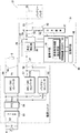
図1は、本発明のバッテリー寿命予測装置をスイッチング電源装置に適用した場合を示す。同図において、1は例えば商用電源51からの交流入力電圧Viが印加される主電源部としての独立した電源ユニットで、この電源ユニット1には交流若しくは直流の出力電圧Voが与えられる一乃至複数の負荷3が接続される。また21は、バックアップ電源として装置に取付けられるバッテリーパックであり、ここではリチウムイオン二次電池や鉛蓄電池などの充放電可能なバッテリー22の他に、好ましくはこのバッテリー22の過放電を防止する過放電保護回路や、過充電を防止する過充電保護回路(いずれも図示せず)が共に組み込まれている。
FIG. 1 shows a case where the battery life prediction apparatus of the present invention is applied to a switching power supply apparatus. In FIG. 1, reference numeral 1 denotes an independent power supply unit as a main power supply unit to which an AC input voltage Vi from a
電源ユニット1の入力端子52,52は、交流入力電圧Viの供給源としての商用電源51に接続され、この商用電源51からの入力電圧Viは整流ブリッジなどを含むフィルタ53と、昇圧チョッパ回路により構成されるPFC(力率改善)回路54とにより、昇圧された直流電圧VDC1に変換される。また、55は直流電圧VDC1を負荷3に適した直流出力電圧Vo1に変換するDC/DCコンバータである。当該直流出力電圧Vo1は、電源ユニット1に設けた出力端子56,56から負荷3に供給されるようになっている。なお、DC/DCコンバータ55や、このDC/DCコンバータ55から取り出せる直流出力電圧Vo1の数は、実施例中のものに限定されない。
The
本実施例では、負荷3に直流出力電圧Vo1を供給するDC/DCコンバータ55の他に、バッテリー22を充電するための給電電圧VCHGを出力端子59,59から出力する別なDC/DCコンバータ57が設けられる。一方、58はこの給電電圧VCHGを出力するDC/DCコンバータ57をバイパスするようにして接続されるバッテリーコンバータで、これは入力電圧Viの低下時または停電時にバッテリー22からの給電電圧を昇圧変換して、DC/DCコンバータ55の入力側に直流電圧VDC2を供給するものである。以上のように、ここに示す電源ユニット1は、交流入力電圧Viを直流出力電圧Vo1に変換するAC/DCユニットとして機能するが、負荷3に交流出力電圧を供給するAC/ACユニットとしての機能を有するものでも構わない。
In this embodiment, in addition to the DC /
前記電源ユニット1とバッテリーパック21との間には、電圧交換ユニット31が接続される。ここでは、電圧変換ユニット31に内蔵する各機能により、電源ユニット1にどのようなバッテリーパック21が取付けられた場合でも、電源ユニット1の内部は一切変更を行なわないようにしている点が注目される。電圧変換ユニット31は、電源ユニット1やバッテリーパック21とは別個の、独立したモジュールとして設けられるが、電源ユニット1の内部に着脱可能に設けてもよいし、バッテリーパック21に着脱可能に設けてもよい。
A
電圧変換ユニット31は外部に露出した端子として、前記バッテリーパック21を接続する電池接続端子23,23の他に、電源ユニット1の給電電圧VCHGが発生する電圧ラインに接続される本体電源接続端子24,24をそれぞれ備えている。また、DC/DCコンバータ57とバッテリー22との間には、このバッテリー22を充電する充電手段としての機能を有し、当該バッテリー22の仕様にあわせて、DC/DCコンバータ55からの給電電圧VCHGを昇圧または降圧するように設計および調整される昇圧・降圧部25が挿入接続される。具体的には、バッテリー22の最適充電電圧がDC/DCコンバータ57からの給電電圧VCHGよりも低いことが予め判っている場合は、当該給電電圧VCHGを最適充電電圧に降圧する降圧チョッパ電源(降圧部)が組み込まれ、逆にバッテリー22の最適充電電圧がDC/DCコンバータ57からの給電電圧VCHGよりも高いことが予め判っている場合は、当該給電電圧VCHGを最適充電電圧に昇圧する昇圧チョッパ電源(昇圧部)が組み込まれる。
In addition to the
また、昇圧・降圧部25からバッテリー22に与える電圧を、このバッテリー22の最適充電電圧に設定・調整するのに、電圧変換ユニット31に与えられる入力電圧(給電電圧VCHG)を検出する手段を設けたり、或いは決められた入力電圧に対し、バッテリー22の端子間電圧を検出する手段を設けたりしてもよい。さらには、二次電池の種類を物理的に判別する電池判別手段を電圧変換ユニット31に備え、使用する二次電池に応じて、降圧部若しくは昇圧部のいずれか一方を動作させる構成としてもよい。こうすれば、どのような二次電池に対しても、電圧変換ユニット31からバッテリーパック21に最適な電圧を供給できる。
Also, a means for detecting the input voltage (feed voltage VCHG) applied to the
一方、入力電圧Viの低下若しくは停電時にバッテリー22を放電させる放電手段としての放電回路27は、昇圧・降圧部25をバイパスして、電圧変換ユニット31の出力端子である一方の電池接続端子23から、電圧変換ユニット31の入力端子である一方の本体電源接続端子24にダイオード28を介して接続される放電ライン29により構成される。このダイオード28は、電源ユニット1からの給電電圧VCHGが昇圧・降圧部25を介さずにバッテリーパック21側に直接供給されるのを阻止する機能を有する。なお、バッテリー22がリチウムイオン二次電池の場合には、バッテリー22の満充電を検出すると、このバッテリー22への給電を停止して、バッテリー22を自己放電させる満充電検出部や、バッテリー22の端子間電圧が所要値にまで低下したのを検出すると、バッテリー22への給電を開始させる低電圧検出部を備えていてもよい。
On the other hand, a
41は、バッテリー22の放電時に、このバッテリー22の出力電流を検出する電流検出器としてのカレントトランスである。ここでの電流検出器はカレントトランスに限定されず、例えば抵抗器を挿入して、その両端間の電圧降下を測定してもよい。また、42はバッテリー22の端子間電圧を検出する電圧検出回路で、ここではバッテリー22の両端間に接続する抵抗器43,44の直列回路で構成され、当該抵抗器43,44の接続点からバッテリー22の端子間電圧に比例した検出電圧が出力されるようになっている。
45は、前記昇圧・降圧部25に内蔵するスイッチング素子(図示せず)にパルス駆動信号を供給すると共に、前記カレントトランス41および電流検出回路42からの検出出力を受けて、バッテリー22の劣化を診断する診断手段としての機能を備えた制御装置である。また46は、例えば製品の出荷前において、バッテリー22の初期使用時にバッテリー22から負荷への出力電流を変化させたときに、このバッテリー22の出力電流と端子間電圧の脈動振幅値(リップルのピーク−ピーク間電圧値)との関係を基本データとして記憶する記憶手段46である。その際、制御装置45は、前記カレントトランス41および電流検出回路42からの検出出力を、内蔵するA/Dコンバータでデジタル信号に変換し、バッテリー22の出力電流と端子間電圧の脈動振幅値をそれぞれ計測して、記憶手段46に記憶させる。特に、記憶手段46は不揮発性のメモリであることが好ましく、これにより出荷前に記憶手段46に記憶される基本データは、電源供給がなくてもその記憶内容が失われないようになっている。
45 supplies a pulse drive signal to a switching element (not shown) built in the step-up / step-down
制御装置45は、内蔵するタイマによって、バッテリー22の使用中にこのバッテリーを前記放電手段により定期的に放電させ、このとき取り込んだバッテリー22の出力電流に対する端子間電圧の脈動振幅値と、記憶手段46から読み出した基本データにある同じ出力電流に対する脈動振幅値との差分値が、予め記憶された設定値を超えると、例えば表示装置や報知装置などの出力装置47に警報信号を出力する診断手段48を備えている。また、ここでの診断手段48は、バッテリー22の使用に伴いその端子間電圧の脈動振幅値が次第に増大するのを利用して、バッテリー22の寿命残存時間を算出する寿命残存時間算出手段49を備えている。すなわち、この寿命残存時間算出手段49は、バッテリー22を放電する際に取り込まれるバッテリー22の出力電流に対する端子間電圧の脈動振幅値と、記憶手段46から読み出した基本データにある同じ出力電流に対する脈動振幅値との差分値との大きさにより、バッテリー22の寿命残存時間を算出して、この算出結果を出力装置47に出力する機能を有する。
The
なお、本実施例における制御装置45は、特に演算速度を速くするために、デジタルシグナルプロセッサ(DSP)を使用している。すなわち、バッテリー22の放電時に取得したデータと、出荷時に記憶手段46に記憶した基本データとを、同じ出力電流の条件をそろえて比較演算し、その結果を、寿命を予測するためのデータテーブルと比較して、予測した寿命を表示または報知するという動作を高速かつ高精度で行なっている。そしてここでは、制御装置45と、記憶手段46と、出力装置47などを含むバッテリー寿命予測装置50が、電源装置である電源ユニット1に組み込まれている。
Note that the
次に、上記構成について、その作用を説明する。商用電源51からの交流入力電圧Viが電源ユニット1内に正常に供給されている場合は、この交流入力電圧Viがフィルタ53およびPFC回路54により、昇圧された直流電圧VDC1に変換される。そして、PFC回路54からの直流電圧VDC1はDC/DCコンバータ55に印加され、このDC/DCコンバータ55で得られた直流出力電圧Vo1が、電源ユニット1に接続する負荷3に与えられると共に、バッテリー22を充電するための給電電圧VCHGがDC/DCコンバータ57から発生する。なお、これらの直流出力電圧Vo1および給電電圧VCHGは、DC/DCコンバータ55,57に内蔵する帰還回路(図示せず)により、その安定化が図られている。
Next, the effect | action is demonstrated about the said structure. When the AC input voltage Vi from the
一方、交流入力電圧Viの低下時若しくは停電時にも、負荷3に一定時間電力を供給させたい場合は、バッテリーパック21と電圧変換ユニット31を装着する。こうすると、DC/DCコンバータ57からの給電電圧VCHGは、昇圧・降圧部32によってリチウムイオン二次電池22の最適充電電圧に変換され、こ最適充電電圧にてバッテリー22が充電される。そのため、電源ユニット1の内部に手を加えなくても、バッテリーパック21に対応した電圧変換ユニット31を単に組み込むだけで、バッテリー22を最適な電圧で充電することができる。
On the other hand, when it is desired to supply power to the load 3 for a certain period of time even when the AC input voltage Vi drops or a power failure occurs, the
上記電圧変換ユニット31を組み込んだ状態で、交流入力電圧Viが低下若しくは停電すると、DC/DCコンバータ57から電圧変換ユニット31の本体電源接続端子24,24に与えられる給電電圧VCHGも低下する。こうなると、放電回路27を構成するダイオード28が導通してバッテリー22から電源ユニット1のバッテリーコンバータ58に給電が行なわれる。これを受けてバッテリーコンバータ58は、バッテリー22からの給電電圧を、PFC回路54からの直流電圧VDC1と略同レベルの直流電圧VDC2に昇圧し、この直流電圧VDC2をDC/DCコンバータ55の入力側に供給する。したがって、DC/DCコンバータ55の出力側に接続した負荷3は、バッテリー22の電力供給を受け続けることになる。
When the AC input voltage Vi decreases or a power failure occurs in the state where the
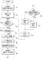
次に、バッテリー寿命予測装置50としての動作を、図2に示すフローチャートに基づき説明すると、ステップS1では、製品としての出荷時に、本体電源接続端子24,24を利用して工具用の電源ユニット1を接続し、負荷3を変えながら、制御装置45が商用電源51からの入力電圧Viを遮断したときのバッテリー22からの出力電流と端子間電圧を、カレントトランス41と電圧検出回路42からの検知出力によりそれぞれ読み込む。このとき、バッテリー22の端子間電圧は、無負荷から全負荷の範囲で何回か読み込むのが好ましい。制御装置45の診断手段48は、電圧検出回路42からの検知出力を解析して、バッテリー22の端子間電圧の脈動振幅値を算出する。こうして得られたバッテリー22の出力電流と端子間電圧の脈動振幅値との関係は、個々のバッテリー22毎に異なる独自の基本データとして記憶手段46に記憶される(ステップS2)。なお、バッテリー22の寿命を予測するためのデータテーブルは、製造時に制御装置45に記憶内蔵されている。
Next, the operation of the battery
その後、バッテリーパック21とこれに対応する電圧変換ユニット31が出荷され、任意の電源ユニット1と組み合わされる。電源装置全体の動作は上述したとおりである。ステップS3において、商用電源51からの交流入力電圧Viが正常に給電されている場合に、診断手段48は次のステップS4において、バッテリー22を放電させるための一定時間が経過したか否かを判断する。一定時間が経過したら、診断手段48は放電手段を構成する図示しないスイッチ手段を利用して、PFC回路54からの直流電圧VDC1を遮断し、バッテリー22を瞬間的に放電状態にさせる(ステップS5)。そして、次のステップS6では、バッテリー22からの出力電流と端子間電圧を、カレントトランス41と電圧検出回路42からの検知出力によりそれぞれ短時間連続して読み込み、その後、前記スイッチ手段を元の状態にして、PFC回路54からの直流電圧VDC1の供給を再開する(ステップS7)。
Thereafter, the
次のステップS8で、診断手段48は電圧検出回路42からの検知出力を解析して、バッテリー22の端子間電圧の脈動振幅値を算出する。そして、記憶手段46に記憶される出荷時の基本データから、同じ出力電流における振幅脈動値との差分値を算出し、この差分値が所定の寿命を予測するためのデータテーブルから得られた所定値を超えているか否かをステップS9で判断する。なお、ステップS6でデータを読み込めば、ステップS7とステップS8とは同時に行ってもよく、順番を入れ替えてもよい。
In the next step S8, the diagnosis means 48 analyzes the detection output from the
そして、今回のバッテリー放電時におけるバッテリー22の端子間電圧の脈動振幅値が許容範囲内にあり、ステップS9で判断される前記差分値が所定値を超えていない場合には、ステップS10にて正常である旨の信号が出力装置47に送出され、出力装置47は正常である旨の表示または報知を行って、次のステップS12でタイマをリセットして、次回の放電チェック(診断)に備える。また今回のバッテリー放電時におけるバッテリー22の端子間電圧の脈動振幅値が許容範囲を超えて増大しており、ステップS9で判断される前記差分値が所定値を超えている場合には、バッテリー21が劣化状態と判断して、出力装置47に警報信号が送出される。当該出力装置47は、ステップS11にてバッテリー22の劣化を知らせる表示または報知を行なうと共に、次のステップS12でタイマをリセットして、次回の放電チェック(診断)に備える。
If the pulsation amplitude value of the voltage between the terminals of the
また、図2に示すフローチャートに加えて、診断手段48に含まれる寿命残存時間算出手段49は、ステップS8で得られた差分値と、予め制御装置45に記憶したデータテーブルとから、バッテリー22の寿命残存時間がどの程度かを算出し、その算出結果を示す信号を出力装置47に送出する。これを受けて出力装置47は、バッテリー22の寿命残存時間を表示または報知することが可能になる。
Further, in addition to the flowchart shown in FIG. 2, the remaining lifetime calculation means 49 included in the diagnosis means 48 uses the difference value obtained in step S8 and the data table stored in the
以上のように上記実施例のバッテリー寿命予測装置50は、バッテリー22を充電する充電手段としての昇圧・降圧部25と、バッテリー22を放電させる放電手段としての放電回路27と、バッテリー22の初期使用時に、このバッテリー22から負荷3への出力電流を変化させながら、出力電流と端子間電圧の脈動振幅値との関係を基本データとして記憶する記憶手段46と、バッテリー22の使用中に、このバッテリー22を放電回路27により定期的に放電させ、このとき取り込んだバッテリー22の出力電流に対する端子間電圧の脈動振幅値と、前記基本データにある脈動振幅値との差分値が設定値を超えると、警報信号を出力する診断手段48とを備えている。
As described above, the battery
本実施例のバッテリー寿命予測装置50は、バッテリー22の劣化が進んでくると、その内部抵抗が高くなってくるために、放電時における端子間電圧の脈動振幅値が大きくなるという特性に着目してなされたものである。すなわち、通常のバッテリー22の使用中に、このバッテリー22を定期的に放電させ、このときのバッテリー22の出力電流と、端子間電圧の脈動振幅値をそれぞれ診断手段48に取り込み、この脈動振幅値がある値を超えて大きくなったら、診断手段48から警報信号を出力する。このとき取り込まれるバッテリー22の端子間電圧の脈動振幅値は、バッテリー22を僅かに放電させるだけで測定可能であり、しかも負荷3を繋いだ状態での測定であるため、短時間で高精度にバッテリー22の劣化状態を診断することができる。
The battery
また、本発明における診断手段48は、前記差分値の大きさにより、バッテリー22の寿命残存時間を算出して、この算出結果を出力する寿命残存時間算出手段49を備えている。
Further, the diagnostic means 48 according to the present invention includes life remaining time calculating means 49 for calculating the remaining life time of the
このような寿命残存時間算出手段49が診断手段48に設けられていれば、単にバッテリー22が寿命に達したことを警報信号で出力するだけでなく、バッテリー22の寿命残存時間がどの程度であるかを出力でき、バッテリー22の寿命時期を前もって知ることが可能になる。
If such a life remaining time calculating means 49 is provided in the diagnostic means 48, it is not only an alarm signal that the
さらに、本実施例の診断手段48はデジタルシグナルプロセッサで構成されているため、バッテリー22の端子間電圧の脈動振幅値を高分解能および高速で演算処理することができ、また、寿命予測を行うための基本データを備えるとともに、高速比較演算ができるので、極めて短時間で高精度にバッテリー22の劣化状態を診断して寿命を予測することができる。
Furthermore, since the diagnostic means 48 of the present embodiment is composed of a digital signal processor, the pulsation amplitude value of the voltage between the terminals of the
また、本実施例のバッテリー寿命予測装置50は、バッテリー22の寿命を懸念するあらゆる電子機器に適用可能であるが、とりわけ直流出力電圧Vo1を常時負荷3に供給する必要のある電源装置たる電源ユニット1に組み込むのが好ましい。こうすると、電源ユニット1自身に上記特徴を有するバッテリー寿命予測装置50が予め組み込まれることになる。
In addition, the battery
なお、本発明は上記実施例に限定されるものではなく、本発明の要旨の範囲において種々の変形実施が可能である。 In addition, this invention is not limited to the said Example, A various deformation | transformation implementation is possible in the range of the summary of this invention.
1 電源ユニット(電源装置)
3 負荷
22 バッテリー
25 昇圧・降圧部(充電手段)
27 放電回路(放電手段)
48 診断手段
49 寿命残存時間算出手段
50 バッテリー寿命予測装置
1 Power supply unit (power supply unit)
3 Load
22 battery
25 Booster / Buck unit (charging means)
27 Discharge circuit (discharge means)
48 Diagnostic tools
49 Means for calculating remaining lifetime
50 Battery life prediction device
Claims (4)
Priority Applications (1)
| Application Number | Priority Date | Filing Date | Title |
|---|---|---|---|
| JP2004104441A JP4147589B2 (en) | 2004-03-31 | 2004-03-31 | Battery life prediction device and power supply device using the same |
Applications Claiming Priority (1)
| Application Number | Priority Date | Filing Date | Title |
|---|---|---|---|
| JP2004104441A JP4147589B2 (en) | 2004-03-31 | 2004-03-31 | Battery life prediction device and power supply device using the same |
Publications (2)
| Publication Number | Publication Date |
|---|---|
| JP2005291803A true JP2005291803A (en) | 2005-10-20 |
| JP4147589B2 JP4147589B2 (en) | 2008-09-10 |
Family
ID=35324909
Family Applications (1)
| Application Number | Title | Priority Date | Filing Date |
|---|---|---|---|
| JP2004104441A Expired - Fee Related JP4147589B2 (en) | 2004-03-31 | 2004-03-31 | Battery life prediction device and power supply device using the same |
Country Status (1)
| Country | Link |
|---|---|
| JP (1) | JP4147589B2 (en) |
Cited By (4)
| Publication number | Priority date | Publication date | Assignee | Title |
|---|---|---|---|---|
| JP2009128194A (en) * | 2007-11-22 | 2009-06-11 | Electric Power Dev Co Ltd | Battery life deterioration judging device and method |
| CN110168841A (en) * | 2016-12-29 | 2019-08-23 | 威拓股份有限公司 | Hybrid battery charger/tester |
| KR20220011777A (en) * | 2019-06-05 | 2022-01-28 | 사일렉트릭, 인크. | Systems, devices and methods of cycle coulometry |
| JP2024513702A (en) * | 2021-03-18 | 2024-03-27 | インターナショナル・ビジネス・マシーンズ・コーポレーション | Selective discharge of rechargeable battery packs across system loads |
Families Citing this family (1)
| Publication number | Priority date | Publication date | Assignee | Title |
|---|---|---|---|---|
| JP5936711B2 (en) | 2012-12-26 | 2016-06-22 | 三菱電機株式会社 | Storage device life prediction apparatus and storage device life prediction method |
-
2004
- 2004-03-31 JP JP2004104441A patent/JP4147589B2/en not_active Expired - Fee Related
Cited By (8)
| Publication number | Priority date | Publication date | Assignee | Title |
|---|---|---|---|---|
| JP2009128194A (en) * | 2007-11-22 | 2009-06-11 | Electric Power Dev Co Ltd | Battery life deterioration judging device and method |
| CN110168841A (en) * | 2016-12-29 | 2019-08-23 | 威拓股份有限公司 | Hybrid battery charger/tester |
| JP2020504994A (en) * | 2016-12-29 | 2020-02-13 | ヴィート エヌブイ | Hybrid battery charger / tester |
| KR20220011777A (en) * | 2019-06-05 | 2022-01-28 | 사일렉트릭, 인크. | Systems, devices and methods of cycle coulometry |
| CN114175349A (en) * | 2019-06-05 | 2022-03-11 | 希利特里克公司 | System apparatus and method for cyclic coulometry |
| KR102468238B1 (en) | 2019-06-05 | 2022-11-16 | 사일렉트릭, 인크. | How to test an electrochemical cell |
| JP2024513702A (en) * | 2021-03-18 | 2024-03-27 | インターナショナル・ビジネス・マシーンズ・コーポレーション | Selective discharge of rechargeable battery packs across system loads |
| JP7786855B2 (en) | 2021-03-18 | 2025-12-16 | インターナショナル・ビジネス・マシーンズ・コーポレーション | Selective Discharge of Rechargeable Battery Packs Across a System Load |
Also Published As
| Publication number | Publication date |
|---|---|
| JP4147589B2 (en) | 2008-09-10 |
Similar Documents
| Publication | Publication Date | Title |
|---|---|---|
| JP5815195B2 (en) | Battery state detection device and battery pack incorporating the same | |
| US7183748B1 (en) | Electric charger and power supply device for portable terminal | |
| US9800066B2 (en) | Electricity distribution device, and controlling method for battery pack | |
| JP4668957B2 (en) | Charge control method and electronic device | |
| JP5225559B2 (en) | Battery pack abnormality determination method and battery pack | |
| JP4486046B2 (en) | Battery pack monitoring apparatus and method | |
| JP5561916B2 (en) | Battery status monitoring device | |
| JP3904489B2 (en) | Charge control circuit, charger, power supply circuit, information processing apparatus, and battery pack | |
| EP1355403A2 (en) | DC backup power supply device and method for diagnosing the same | |
| JP4960022B2 (en) | Battery pack and abnormality determination method thereof | |
| US7535201B2 (en) | Uninterruptible power supply system | |
| JP3859608B2 (en) | Battery pack, electronic device, remaining battery level prediction system, and semiconductor device | |
| KR20080104861A (en) | Inverter circuit control device and inverter circuit for battery life estimation | |
| JP4846755B2 (en) | Portable electronic devices | |
| JP4147589B2 (en) | Battery life prediction device and power supply device using the same | |
| JP2010019653A (en) | Battery residual capacity calculating system | |
| JP3317513B2 (en) | Charging circuit | |
| JP4079108B2 (en) | Uninterruptible power system | |
| JP4671590B2 (en) | Power supply type determination method, power supply type determination apparatus, and power supply apparatus | |
| US7602150B2 (en) | Battery device for electronic apparatus with rechargeable secondary battery, fuel cell and run time computing unit | |
| JP2003009407A (en) | Information terminal equipment | |
| JP4419093B2 (en) | Uninterruptible power supply and control method, and power storage device and method | |
| JP3135442B2 (en) | Battery life detector | |
| JP2004180428A (en) | On line determination method of battery deterioration, deterioration determination method of battery mounted on uninterruptible power supplying apparatus and uninterruptible power supplying apparatus | |
| JP2014149165A (en) | Dc power supply apparatus, degradation determination method of storage battery in dc power supply apparatus, storage battery degradation determination apparatus |
Legal Events
| Date | Code | Title | Description |
|---|---|---|---|
| A621 | Written request for application examination |
Free format text: JAPANESE INTERMEDIATE CODE: A621 Effective date: 20051207 |
|
| A977 | Report on retrieval |
Free format text: JAPANESE INTERMEDIATE CODE: A971007 Effective date: 20080514 |
|
| TRDD | Decision of grant or rejection written | ||
| A01 | Written decision to grant a patent or to grant a registration (utility model) |
Free format text: JAPANESE INTERMEDIATE CODE: A01 Effective date: 20080602 |
|
| A01 | Written decision to grant a patent or to grant a registration (utility model) |
Free format text: JAPANESE INTERMEDIATE CODE: A01 |
|
| A61 | First payment of annual fees (during grant procedure) |
Free format text: JAPANESE INTERMEDIATE CODE: A61 Effective date: 20080615 |
|
| FPAY | Renewal fee payment (event date is renewal date of database) |
Free format text: PAYMENT UNTIL: 20110704 Year of fee payment: 3 |
|
| R150 | Certificate of patent or registration of utility model |
Free format text: JAPANESE INTERMEDIATE CODE: R150 Ref document number: 4147589 Country of ref document: JP Free format text: JAPANESE INTERMEDIATE CODE: R150 |
|
| FPAY | Renewal fee payment (event date is renewal date of database) |
Free format text: PAYMENT UNTIL: 20110704 Year of fee payment: 3 |
|
| S533 | Written request for registration of change of name |
Free format text: JAPANESE INTERMEDIATE CODE: R313533 |
|
| FPAY | Renewal fee payment (event date is renewal date of database) |
Free format text: PAYMENT UNTIL: 20110704 Year of fee payment: 3 |
|
| R350 | Written notification of registration of transfer |
Free format text: JAPANESE INTERMEDIATE CODE: R350 |
|
| S531 | Written request for registration of change of domicile |
Free format text: JAPANESE INTERMEDIATE CODE: R313531 |
|
| FPAY | Renewal fee payment (event date is renewal date of database) |
Free format text: PAYMENT UNTIL: 20110704 Year of fee payment: 3 |
|
| R350 | Written notification of registration of transfer |
Free format text: JAPANESE INTERMEDIATE CODE: R350 |
|
| FPAY | Renewal fee payment (event date is renewal date of database) |
Free format text: PAYMENT UNTIL: 20110704 Year of fee payment: 3 |
|
| FPAY | Renewal fee payment (event date is renewal date of database) |
Free format text: PAYMENT UNTIL: 20120704 Year of fee payment: 4 |
|
| FPAY | Renewal fee payment (event date is renewal date of database) |
Free format text: PAYMENT UNTIL: 20130704 Year of fee payment: 5 |
|
| LAPS | Cancellation because of no payment of annual fees |