JP2005291727A - Biochemical analyzer - Google Patents
Biochemical analyzer Download PDFInfo
- Publication number
- JP2005291727A JP2005291727A JP2004102757A JP2004102757A JP2005291727A JP 2005291727 A JP2005291727 A JP 2005291727A JP 2004102757 A JP2004102757 A JP 2004102757A JP 2004102757 A JP2004102757 A JP 2004102757A JP 2005291727 A JP2005291727 A JP 2005291727A
- Authority
- JP
- Japan
- Prior art keywords
- sample
- reagent
- probe
- suction
- cuvette
- Prior art date
- Legal status (The legal status is an assumption and is not a legal conclusion. Google has not performed a legal analysis and makes no representation as to the accuracy of the status listed.)
- Withdrawn
Links
- 239000007788 liquid Substances 0.000 claims abstract description 88
- 239000003153 chemical reaction reagent Substances 0.000 claims abstract description 64
- 238000012742 biochemical analysis Methods 0.000 claims abstract description 8
- 238000007599 discharging Methods 0.000 claims abstract description 6
- 238000005259 measurement Methods 0.000 claims description 21
- 239000000523 sample Substances 0.000 abstract description 155
- 230000005587 bubbling Effects 0.000 abstract 1
- 238000004140 cleaning Methods 0.000 description 39
- 238000005070 sampling Methods 0.000 description 10
- 238000010586 diagram Methods 0.000 description 9
- 239000012488 sample solution Substances 0.000 description 5
- 238000003756 stirring Methods 0.000 description 5
- 238000001514 detection method Methods 0.000 description 4
- XLYOFNOQVPJJNP-UHFFFAOYSA-N water Substances O XLYOFNOQVPJJNP-UHFFFAOYSA-N 0.000 description 4
- 239000008280 blood Substances 0.000 description 3
- 210000004369 blood Anatomy 0.000 description 3
- 238000000691 measurement method Methods 0.000 description 3
- 238000005406 washing Methods 0.000 description 3
- 238000005187 foaming Methods 0.000 description 2
- 210000002700 urine Anatomy 0.000 description 2
- 238000013019 agitation Methods 0.000 description 1
- 238000001816 cooling Methods 0.000 description 1
- 230000003028 elevating effect Effects 0.000 description 1
- 230000002550 fecal effect Effects 0.000 description 1
- 210000003608 fece Anatomy 0.000 description 1
- 238000000034 method Methods 0.000 description 1
- 239000000843 powder Substances 0.000 description 1
- 239000002096 quantum dot Substances 0.000 description 1
Images
Landscapes
- Automatic Analysis And Handling Materials Therefor (AREA)
Abstract
Description
本発明は、測定容器内で試薬と検体を反応させ検体の生化学分析を行なう生化学分析装置に関する。 The present invention relates to a biochemical analyzer that performs a biochemical analysis of a specimen by reacting a reagent and the specimen in a measurement container.
人体の血液、尿、便等を検体とし、キュベットと呼ばれる透明の測定容器内にこの検体と試薬を注入して反応させ、その検体と試薬とからなる試料液の反応による呈色を光学的に測定することにより検体の生化学分析を行なう生化学分析装置が知られている(例えば特許文献1参照)。 Using human blood, urine, feces, etc. as a sample, inject the sample and reagent into a transparent measurement container called a cuvette to react, and optically display the color produced by the reaction of the sample solution consisting of the sample and the reagent. There is known a biochemical analyzer that performs biochemical analysis of a specimen by measuring (see, for example, Patent Document 1).
キュベット内に検体や試薬を注入するには、その検体や試薬を検体容器や試薬容器から吸入してキュベットに分注する中空のプローブを備え、その中空のプローブに検体や試薬を吸入させて分注する構成が採用される(特許文献2参照)。
上掲の特許文献2には、検体あるいは試薬等の試料液をキュベットに分注するにあたり、プローブ(ノズル)の先端とキュベット(反応セル)の底面との間が最適距離となるようにプローブ(ノズル)の高さ位置を調整して分注することが提案されている。この特許文献1中には、分注量が5μl(マイクロリットル)未満であれば最適距離を実質的に零とし、分注量が5μl以上であれば1mm乃至2mmの範囲の所定の距離とする、分注量が微量(5μl以下)である場合、ノズルの先端から吐出された試料は、先端と接触している反応セルの底面をつたって反応セルに分注される、一方、分注量が多量(5μl以上)である場合、先端から吐出された試料は自重で反応セルに落下し分注される、ここで、先端は、反応セルの底面と所定の距離だけ離してあるので、分注された試料がノズルに付着することはない、と記載されている。 In the above-mentioned Patent Document 2, in dispensing a sample solution such as a specimen or a reagent into a cuvette, a probe (nozzle) and a probe (nozzle) are arranged so that an optimum distance is provided between the tip of the probe (nozzle) and the bottom of the cuvette (reaction cell). It has been proposed to dispense by adjusting the height position of the nozzle. In Patent Document 1, the optimum distance is substantially zero if the dispensed amount is less than 5 μl (microliter), and the prescribed distance in the range of 1 mm to 2 mm if the dispensed amount is 5 μl or more. When the dispensing amount is very small (5 μl or less), the sample discharged from the tip of the nozzle is dispensed into the reaction cell through the bottom surface of the reaction cell that is in contact with the tip. Is a large amount (5 μl or more), the sample discharged from the tip falls into the reaction cell by its own weight and is dispensed. Here, the tip is separated from the bottom surface of the reaction cell by a predetermined distance. It is described that the injected sample does not adhere to the nozzle.
この特許文献2にはキュベット(反応セル)の内径寸法は記載されておらず、キュベット(反応セル)内に分注された試料液の高さとプローブ(ノズル)の先端高さとの関係は不明であるが、プローブ(ノズル)の先端が分注後の試料液中に入り込んでいるとそのプローブ(ノズル)に試料液を分注したときに空気も試料液容器に吐出されることになって試料液の飛散が生じたり試料液中に泡が発生するおそれがある。あるいは、プローブ(ノズル)の先端高さが分注後のキュベット(反応セル)に試料液の液面よりも高い場合、分注した試料液が水滴になってプローブ(ノズル)の先端に付いたままとなってしまうおそれがあり、分注量の誤差要因となる。 This patent document 2 does not describe the inner diameter of the cuvette (reaction cell), and the relationship between the height of the sample solution dispensed in the cuvette (reaction cell) and the tip height of the probe (nozzle) is unknown. However, if the tip of the probe (nozzle) enters the sample liquid after dispensing, the sample liquid is dispensed to the probe (nozzle), and air is also discharged into the sample liquid container. There is a possibility that the liquid may be scattered or bubbles may be generated in the sample liquid. Alternatively, when the tip height of the probe (nozzle) is higher than the liquid level of the sample liquid in the dispensed cuvette (reaction cell), the dispensed sample liquid becomes water droplets and attaches to the tip of the probe (nozzle). There is a risk that it will remain, causing an error in the dispensing amount.
本発明は、上記事情に鑑み、検体や試薬等の試料液を発泡等を避けながら正確な量だけ分注することのできる機能を備えた生化学分析装置を提供することを目的とする。 In view of the above circumstances, an object of the present invention is to provide a biochemical analyzer having a function capable of dispensing sample liquids such as specimens and reagents by an accurate amount while avoiding foaming.
上記目的を達成する本発明の生化学分析装置は、測定容器内で試薬と検体を反応させ検体の生化学分析を行なう生化学分析装置において、試薬あるいは検体を吸引および吐出する吸引吐出手段と、その吸引吐出手段が測定容器内に試薬あるいは検体を吐出するにあたり、吐出終了時の吸引吐出手段の下端が測定容器内の吐出終了時の液面高さに応じた高さとなるように吸引吐出手段の高さ位置を制御する吸引吐出手段昇降制御部とを備えたことを特徴とする。 The biochemical analyzer of the present invention that achieves the above object is a biochemical analyzer that performs a biochemical analysis of a sample by reacting the reagent and the sample in a measurement container, and a suction / discharge means for sucking and discharging the reagent or the sample, When the suction / discharge means discharges the reagent or sample into the measurement container, the suction / discharge means is such that the lower end of the suction / discharge means at the end of the discharge becomes a height corresponding to the liquid level at the end of the discharge in the measurement container. And a suction / ejecting means lifting / lowering control unit for controlling the height position.
尚、上記の「吐出終了時の吸引吐出手段の下端」は、吐出終了時点について言及したものである。 The above-mentioned “lower end of the suction / discharge means at the end of discharge” refers to the discharge end point.
ここで、本発明の生化学分析装置において、試薬と検体の保管された位置から吸引して、測定容器のある吐出位置まで吸引吐出手段を移動させる手段を有していることが好ましい。 Here, the biochemical analyzer of the present invention preferably includes means for sucking from the position where the reagent and specimen are stored and moving the suction / discharge means to a discharge position where the measurement container is located.
また、本発明の生化学分析装置において、上記吸引吐出手段昇降制御部は、測定容器内に既に試薬あるいは検体がある場合には、分注しようとしている試薬または検体の測定容器への分注が終了した時点の液面高さと一致する高さ位置で、吸引吐出手段を停止させることが好ましい。 Further, in the biochemical analyzer of the present invention, the suction / discharge means elevating control unit can dispense the reagent or sample to be dispensed into the measurement container when the reagent or sample is already present in the measurement container. It is preferable to stop the suction / discharge means at a height position that coincides with the liquid level at the time of completion.
本発明の生化学分析装置は、測定容器内の吐出終了時の液面高さを意識して吐出終了時の吸引吐出手段の下端をその吐出終了時の液面高さに応じた高さ位置となるように制御するものであるため、吸引吐出手段先端に水滴を残したり泡が発生することが防止され、泡の発生を避けつつ正確な量の分注が可能となる。 The biochemical analyzer of the present invention is designed so that the lower end of the suction / discharge means at the end of discharge is in accordance with the liquid level at the end of discharge in consideration of the liquid level at the end of discharge in the measurement container. Therefore, it is possible to prevent water droplets or bubbles from being generated at the tip of the suction and discharge means, and to dispense an accurate amount while avoiding the generation of bubbles.
以下、本発明の実施形態について説明する。 Hereinafter, embodiments of the present invention will be described.
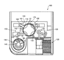
図1は、生化学分析装置の一実施形態を示す概要図である。 FIG. 1 is a schematic diagram showing an embodiment of a biochemical analyzer.
この生化学分析装置100には、ターンテーブル110が備えられており、そのターンテーブル110には、多数のキュベット20が円状に配置されている。
This
そのターンテーブル110の周囲には、検体供給部120、検体サンプリング部130、試薬保管部140、試薬サンプリング部150、撹拌部160、反応部170、および洗浄部180が配備されている。
Around the
検体供給部120には、多数の検体(例えば人体の血液、尿、便等)が各容器に入って配列されており、検体サンプリング部130には、その容器から検体を吸引してターンテーブル110上の多数の測定容器としてのキュベット20のうちのあらかじめプログラムされたキュベットに注入する検体ピペット131が備えられている。この検体ピペット131は、回転軸132を中心にして、検体供給部120と、洗浄部133と、ターンテーブル110上のキュベット20との間で往復回動し、検体供給部120に配列された検体容器から検体を吸引してその検体をターンテーブル110上のキュベット20に注入し、洗浄部133で次の検体の吸引のために洗浄される。
A large number of samples (for example, human blood, urine, stool, etc.) are arranged in each container in the
また、試薬保冷庫140は、試薬が入った試薬容器141を収容して所定の冷却温度に保冷するものであり、また、その試薬保冷庫140の上蓋142には吸入口143が設けられている。その試薬保冷庫140内の試薬容器141はターンテーブル上に置かれていて回転自在となっており、所望の試薬の入った試薬容器が吸入口143の下に配置されるようにそのターンテーブルが回転する。試薬サンプリング部150には、試薬ピペット151が備えられており、その試薬ピペット151は、回転軸152を中心にして、試薬保冷庫140の吸引口143と、洗浄部153と、ターンテーブル110上のキュベット20との間で往復回動し、試薬ピペット151の先端のプローブ(図示せず)を試薬保冷庫140の上蓋142の吸入口143に挿入してその下にある試薬容器141内の試薬を吸引し、その試薬をターンテーブル110上のキュベット20に注入し、洗浄部153で次の試薬の吸引のために洗浄される。
The
撹拌部160には、先端に棒状の撹拌子(図示せず)を備えた攪拌器161が備えられている。この撹拌器161は、回転軸162を中心にして、ターンテーブル110上のキュベット20と洗浄部163との間で往復回動し、キュベット20内に撹拌子を挿入してそのキュベット20内に注入されている検体と試薬を撹拌、混合し、洗浄部163ではその先端の撹拌子が次のキュベットが撹拌、混合のために洗浄される。
The stirring
反応部170には、キュベット20内の撹拌、混合された検体と試薬とからなる試料液の呈色反応の濃度検出のための測定を行なう測定器(図示せず)が配置されており、これにより検体の生化学分析が行なわれる。
The
さらに洗浄部180では、ターンテーブル110上の反応部170における測定の終了したキュベット20が洗浄され、次の検体の生化学分析のために再利用される。
Further, in the
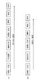
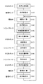
図2は、図1の生化学分析装置の動作シーケンス例を示す図である。 FIG. 2 is a diagram showing an example of an operation sequence of the biochemical analyzer of FIG.
図2(A)は、一般的な生化学分析を行なうときの動作シーケンスであり、先ず、ターンテーブル110上のあるキュベット20に試薬1が分注され、そのまま5分間、所定の温度に安定するよう温度調節が行なわれる。次いでその同じキュベット20に検体が分注され、さらに試薬2が分注され、撹拌されて測定が行なわれ、最後にそのキュベット20が洗浄される。この間約10分ほどの時間がかかる。このような動作シーケンスが、ターンテーブル110に載っている多数のキュベット20について並列的に実行される。
FIG. 2A shows an operation sequence when performing general biochemical analysis. First, the reagent 1 is dispensed into a
図2(B)は、便潜血測定時の動作シーケンスである。この場合、順に試薬1分注、検体分注、試薬2分注が行なわれ、撹拌、測定、洗浄が行なわれて、1検体あたり約6分で終了する。この場合も、ターンテーブル110に載せられている多数のキュベット20について、この動作シーケンスが並行的に実行される。
FIG. 2B shows an operation sequence during fecal occult blood measurement. In this case, reagent 1 dispensing, sample dispensing, and reagent 2 dispensing are sequentially performed, stirring, measurement, and washing are performed, and the process is completed in about 6 minutes per sample. Also in this case, this operation sequence is executed in parallel for a large number of
図1の生化学分析装置100には、図2(A),(B)に例示するような動作シーケンスが複数用意されており、その目的に応じて適切な動作シーケンスに切り替えられる。図1の生化学分析装置100では、動作シーケンスの切り替えは、オペレータによる手動操作で行われるが、その他にも、検体の種類に応じた検体容器を用い、その検体容器の種類を検出して動作シーケスを切り替えるようにしてもよい。
The
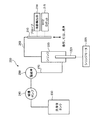
図3は、図1に示す生化学分析装置100の、検体サンプリング部130に検体ピペット131として示した、あるいは試薬サンプリング部150に試薬ピペット151として示した試料分注装置の構成図である。
FIG. 3 is a configuration diagram of the sample dispensing apparatus shown as the sample pipette 131 in the
この試料分注装置200には、吸引吐出手段としてのプローブ210と、シリンジ220と、洗浄液タンク230と、循環ポンプ240と、電磁弁250とが備えられており、プローブ210とシリンジ220との間は可撓性のチューブ260で接続され、洗浄液タンク230から循環ポンプ240および電磁弁250を経由してシリンジ220に至る経路は、配管270で洗浄液の流路が形成されている。
The
ここで、プローブ210は、試料液(試薬あるいは検体)を吸引、吐出するものであり、XYZロボット215によりその水平面上の位置(X,Y)と高さ位置(Z)が制御される。またこのプローブ210には、プローブ210の先端が液面に接したことを検出する液面検出部216が接続されている。またシリンジ220は、シリンジモータ225によりピストン221が駆動されることにより、プローブ210に、制御された量の試料液(試薬あるいは検体)を吸引および吐出させるものである。
Here, the
洗浄液タンク230には洗浄液(ここでは純水)が収容されており、循環ポンプ240は、洗浄液タンク230内の洗浄液を、配管270、シリンジ220、チューブ260を経由してプローブ210に送液する。
A cleaning liquid (pure water here) is stored in the cleaning
ここで、循環ポンプ240とシリンジ220との間には、配管270による洗浄液の流路を開閉する電磁弁250が配備されている。
Here, between the
XYZロボット215、シリンジモータ225、電磁弁250および循環ポンプ240の動作および動作タイミングは、後述する制御部(図4参照)により制御される。
The operations and operation timings of the
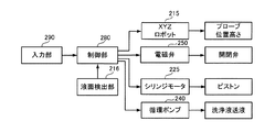
図4は、図3に示す試料分注装置の制御系統図である。 FIG. 4 is a control system diagram of the sample dispensing apparatus shown in FIG.
図1に示す生化学分析装置100の全体の制御を担うホスト制御部(図示せず)から、入力部290を介して、図3に示す試料分注装置の制御を担う制御部280に向けて、この試料分注装置280の動作に必要な制御情報が入力され、この制御部280は、その制御情報に従って、図3にも示すXYZロボット215、電磁弁250、シリンジモータ225および循環ポンプ240の動作および動作タイミングを制御する。XYZロボット215はプローブ210(図3参照)の位置と高さを制御し、電磁弁250は、その電磁弁250に備えられ開閉弁を制御することにより配管270による洗浄液の流路を開閉する。また、シリンジモータ225は、シリンジ220のピストン221を制御してプローブ210への試料液の吸入、吐出を制御する。さらに循環ポンプ240は、洗浄液タンク230内の洗浄液の送液を制御する。また、液面検出部216では、プローブ210の先端が試料液の液面に接触したか否かが検出され、その検出結果が制御部280に入力される。
From a host control unit (not shown) responsible for overall control of the
図5は、図4の制御部による、図3の試料分注装置の制御シーケンスを示す図である。ここでは、図3および図4も合わせて参照しながら説明する。 FIG. 5 is a diagram showing a control sequence of the sample dispensing apparatus of FIG. 3 by the control unit of FIG. Here, description will be made with reference to FIGS. 3 and 4 together.
先ずXYZロボット215によりプローブ210が洗浄位置に移動される(ステップS11)。
First, the
図1に示すように、検体サンプリング130、試薬サンプリング150のそれぞれについて洗浄部133,153が設けられている。
As shown in FIG. 1, cleaning
次いで、循環ポンプ240により洗浄液が送液されてプローブ210に送り込まれ、プローブ210先端から吐出されてプロープ210が洗浄される(ステップS12)。その後、電磁弁250による開閉弁が閉じられて配管270による洗浄液の流路が遮断される(ステップS13)。
Next, the cleaning liquid is sent by the
さらにその後、シリンジモータ225が動作し、ピストン221を動かしてプローブ210から洗浄液をさらに吐出させ(ステップS14)、次いで、シリンジモータ225によりピストン221を逆方向に動かして、洗浄液と試薬との混合を避けることを目的とした中間空気層形成のためにプローブ210の先端部分に空気を吸引する(ステップS15)。この空気層の、プローブ210の長手方向の寸法は5mm程度である。
Thereafter, the
次いで、XYZロボット215により、試料液を吸引するための吸引位置(図1の検体供給部120あるいは試料保冷庫140)にプローブ210を移動し(ステップS16)、プローブ210を下げて行って途中で試料液の液面が検出されると(ステップS17)、その液面高さを基準にしてプローブ21の高さを決定し、シリンジモータ225を動作させて試料を吸引する(ステップS18)。
Next, the
次いで、XYZロボット215により、プローブ210を今度は吐出位置(図1の生化学分析装置100のターンテーブル110上のキュベット20)に移動させる(ステップS19)。このとき、そのキュビット20の内寸法、そのキュベット20に既に試薬や検体が分注された状態にあるか否か、分注された状態にあるときのその液面の高さ位置は、既に分かっており、また、今回分注しようとしている試料液の量も分かっており、プローブ210は、その先端が今回分注しようとしている試料液のそのキュベット20への分注が終了した時点の液面高さと同一の高さ位置となるように高さ位置が調整される。
Next, the
次いで、シリンジモータ225が動作しピストン221を動かして、プローブ210内の試料液がそのプローブ210からキュベット20内に吐出される(ステップS20)。
Next, the
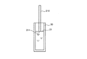
図6は、試料吐出後の液面高さとプローブ先端の高さとの位置関係を示す図である。 FIG. 6 is a diagram showing a positional relationship between the liquid level after the sample is discharged and the height of the probe tip.
プローブ210からキュベット20に試料液を吐出した後のキュベット20の液面高さ21とプローブ210の先端211の高さを一致させている。
The
このように、プローブ210の先端は、その試料液の吐出が終了した時点における液面高さと同じ高さ位置にあるため、プローブ210の先端に試料液が水滴となって付着したままになるのを避けることができる。このプローブ210から試料液を吐出する際、シリンジ220のピストン221のバックラッシュ補正等のために、ステップS15で吸引した空気層の空気もある程度(例えば2マイクロリットル程度)吐出されるが、プローブ210の先端がキュベット20内の試料液中に浸漬していると空気の吐出により試料が飛散したり試料中に泡が発生するおそれがある。これに対し、ここでは、プローブ210はキュベット20内の試料液中には浸漬されておらず、試料液の飛散が防止され、試料液中への空気の泡の発生も防止される。したがって、プローブ210からキュベット20への試料の分注量の精度を高精度に保つことができる。
In this way, the tip of the
図5に戻って説明を続ける。 Returning to FIG.
プローブ210からキュベット20への試料の吐出(分注)(ステップS20)が終了すると、今度はXYZロボット215によりプローブ210が再び洗浄位置に移動され(ステップS21)、電磁弁250が動作しその開閉弁が開かれて配管270による洗浄液の流路が形成され(ステップS22)、さらに循環ポンプ240が動作して、洗浄液タンク230中の洗浄液230が、配管270、シリンジ220、チューブ260およびプローブ210に流入し、プローブ210の先端から洗浄液を流し出してプローブ210が洗浄される(ステップS23)。その後、電磁弁250により洗浄液の流路が断たれ(ステップS13)、今度はシリンジモータ225による、プローブ210の先端からの洗浄液吐出が行なわれる(ステップS14)。以上の動作シーケンスが繰り返されて、図1の生化学分析装置100のターンテーブル110に並んだ多数のキュベット20への検体や試薬の分注が行なわれる。
When the discharge (dispensing) of the sample from the
ここで、ステップS12あるいはステップS23において、プローブ210内に洗浄液が送り込まれてプローブ210の先端から吐出されプローブ210が洗浄されているにもかかわらず、ステップS14で洗浄液をさらに吐出させるのは、ステップS13で電磁弁250が動作し洗浄液の流路が遮断された瞬間に電磁弁250の振動等に起因してプローブ210の先端において洗浄液中に空気の泡が混入するからである。これをこのままにして、ステップS14を省いて動作シーケンスを進めると、プローブ210に吸引される試料液の吸引量が安定せず、分注量の精度が下がるという問題や、混入した空気の泡がプローブ210の先端の内壁面に付着し、そこに試料液が吸引されると、その泡を形成している洗浄液が試料液に混入してしまいその試料液の濃度や量を変化させてしまうという問題が生じる。
Here, in step S12 or step S23, although the cleaning liquid is fed into the
そこでここでは上記のステップS14を置き、電磁弁250で洗浄液の流路を遮断した後、シリンジモータ225を動作させてプローブ210の先端から洗浄液をさらに吐出させている。こうすることにより、プローブ210の先端の、空気の泡が混入した部分が無くなり、その後、空気層を形成し(ステップS15)、試料液を、高精度に制御された量だけ吸引、吐出することができる。
Therefore, here, step S14 described above is set, the flow path of the cleaning liquid is blocked by the
尚、上記実施形態では図6に示すように、プローブ210からキュベット20に試料液を吐出した後のキュベット20の液面高さ21とプローブ210の先端211の高さを一致させているが、本発明では必ずしも同一高さである必要はなく、プローブ先端が液面高さに応じた高さであって、吐出終了時にプローブ先端に液滴が付いたままになることを避け、かつ、試料液中への発泡を避けることができる範囲内の高さであればよい。
In the above embodiment, as shown in FIG. 6, the
また、本実施の形態では、吸引吐出手段としてプローブ21を使用しているが、これに限定されるものではなく、ノズル、ノズルチップ等であっても適用が可能である。
In the present embodiment, the
さらにまた、本実施の形態では、測定容器をキュベット20としているが、これに限定されるものではなく、試験管等で測定方法に合った容器であれば適用が可能である。
Furthermore, in the present embodiment, the
また、本実施の形態では、攪拌部を必要としているが、検体の分注時に攪拌が十分に行われれば必ずしも必要とはならない。 Moreover, in this Embodiment, although the stirring part is required, if stirring is fully performed at the time of sample dispensing, it is not necessarily required.
また、本実施の形態では、キュベット20に測定を照射し透過光を検出しているが、測定方法に限定されるものではなく、電気的な測定方法等も適用が可能である。
In this embodiment, the
また、本実施の形態では、試薬は液体で分注しているとしているが、これに限定されるものではなく、試薬は粉末状であっても、あらかじめキュベット20内に入れられてあっても適用が可能である。
In the present embodiment, the reagent is dispensed as a liquid. However, the present invention is not limited to this, and the reagent may be in a powder form or may be placed in the
20 キュベット
100 生化学分析装置
110 ターンテーブル
120 検体供給部
130 検体サンプリング部
140 試薬保管庫
150 試薬サンプリング部
160 攪拌部
170 反応部
180 洗浄部
200 試料分注装置
210 プローブ
211 先端
215 XYZロボット
216 液面検出部
220 シリンジ
221 ピストン
225 シリンジモータ
230 洗浄液タンク
240 循環ポンプ
250 電磁弁
260 チューブ
270 配管
20
Claims (3)
試薬あるいは検体を吸引および吐出する吸引吐出手段と、
前記吸引吐出手段が予め所定量の試薬あるいは検体を吸引した状態で、前記吸引吐出手段が前記測定容器内に試薬あるいは検体を吐出するにあたり、吐出終了時の該吸引吐出手段の下端が該測定容器内の吐出終了時の液面高さに応じた高さとなるように該吸引吐出手段の高さ位置を制御する吸引吐出手段昇降制御部とを備えたことを特徴とする生化学分析装置。 In a biochemical analyzer that performs a biochemical analysis of a sample by reacting a reagent with the sample in a measurement container,
Aspirating and discharging means for aspirating and discharging a reagent or specimen;
When the suction / discharge means discharges the reagent or sample into the measurement container with the suction / discharge means sucking a predetermined amount of the reagent or sample in advance, the lower end of the suction / discharge means at the end of the discharge is the measurement container. A biochemical analyzer comprising: a suction / discharge means lifting / lowering control unit for controlling the height position of the suction / discharge means so as to be a height corresponding to the liquid level at the end of the discharge.
Priority Applications (1)
| Application Number | Priority Date | Filing Date | Title |
|---|---|---|---|
| JP2004102757A JP2005291727A (en) | 2004-03-31 | 2004-03-31 | Biochemical analyzer |
Applications Claiming Priority (1)
| Application Number | Priority Date | Filing Date | Title |
|---|---|---|---|
| JP2004102757A JP2005291727A (en) | 2004-03-31 | 2004-03-31 | Biochemical analyzer |
Publications (1)
| Publication Number | Publication Date |
|---|---|
| JP2005291727A true JP2005291727A (en) | 2005-10-20 |
Family
ID=35324840
Family Applications (1)
| Application Number | Title | Priority Date | Filing Date |
|---|---|---|---|
| JP2004102757A Withdrawn JP2005291727A (en) | 2004-03-31 | 2004-03-31 | Biochemical analyzer |
Country Status (1)
| Country | Link |
|---|---|
| JP (1) | JP2005291727A (en) |
Cited By (1)
| Publication number | Priority date | Publication date | Assignee | Title |
|---|---|---|---|---|
| JP2013061360A (en) * | 2013-01-10 | 2013-04-04 | Toshiba Corp | Automatic analyzer |
-
2004
- 2004-03-31 JP JP2004102757A patent/JP2005291727A/en not_active Withdrawn
Cited By (1)
| Publication number | Priority date | Publication date | Assignee | Title |
|---|---|---|---|---|
| JP2013061360A (en) * | 2013-01-10 | 2013-04-04 | Toshiba Corp | Automatic analyzer |
Similar Documents
| Publication | Publication Date | Title |
|---|---|---|
| EP2259073B1 (en) | Method of cleaning nozzle | |
| CN108700610B (en) | Automatic analyzer and cleaning method | |
| JP7305891B2 (en) | automatic analyzer | |
| WO2012105398A1 (en) | Automatic analyzing device | |
| JP2005241442A (en) | Cleaning device and method, and analyzer using it | |
| JP5661259B2 (en) | Automatic analyzer | |
| JP2003232799A (en) | Automatic analyzer | |
| JPH04115136A (en) | Particle measuring apparatus | |
| JPWO2019078030A1 (en) | Cleaning method for automatic analyzer and probe | |
| CN1900721B (en) | Automatic analysis device and dispensing method thereof | |
| JP7451252B2 (en) | automatic analyzer | |
| JP2014206381A (en) | Automatic analyzer | |
| JP2981070B2 (en) | Dispensing device capable of detergent cleaning and its cleaning method | |
| JPS6366466A (en) | Discrete type automatic analyzer | |
| JP2005257491A (en) | Automatic analyzer | |
| JP2008241508A (en) | Liquid stirring method | |
| EP1335853B1 (en) | Sample dispensing with liquid delivery without crossover | |
| JP2005249585A (en) | Autoanalyzer and analysis method | |
| JPH11153603A (en) | Biochemical automatic analyzer | |
| JP2005291729A (en) | Biochemical analyzer | |
| JP2005291727A (en) | Biochemical analyzer | |
| JP2008304334A (en) | Dispenser and autoanalyzer | |
| JP6355960B2 (en) | CLINICAL INSPECTION DEVICE AND CONTAINER CLEANING METHOD | |
| CN108713146B (en) | Solution discharge device and method for controlling discharge of solution | |
| JPH0639266A (en) | Liquid stirring method and apparatus |
Legal Events
| Date | Code | Title | Description |
|---|---|---|---|
| A300 | Withdrawal of application because of no request for examination |
Free format text: JAPANESE INTERMEDIATE CODE: A300 Effective date: 20070605 |