JP2005291656A - Vacuum drying method for tablets and granules - Google Patents
Vacuum drying method for tablets and granules Download PDFInfo
- Publication number
- JP2005291656A JP2005291656A JP2004110072A JP2004110072A JP2005291656A JP 2005291656 A JP2005291656 A JP 2005291656A JP 2004110072 A JP2004110072 A JP 2004110072A JP 2004110072 A JP2004110072 A JP 2004110072A JP 2005291656 A JP2005291656 A JP 2005291656A
- Authority
- JP
- Japan
- Prior art keywords
- container
- dried
- vacuum
- tablets
- guide member
- Prior art date
- Legal status (The legal status is an assumption and is not a legal conclusion. Google has not performed a legal analysis and makes no representation as to the accuracy of the status listed.)
- Pending
Links
Images


Landscapes
- Drying Of Solid Materials (AREA)
- Freezing, Cooling And Drying Of Foods (AREA)
Abstract
【課題】 比較的大容量の容器を使用した場合でも、より効率的に乾燥させることができる錠・粉粒体の真空乾燥方法を提供すること。
【解決手段】 錠剤又は粉粒体からなる被乾燥物3が投入された上部開口の容器2を真空室1内に収容し、真空室1内を真空状態に保ちながら前記容器2の被乾燥物3の積層内の下部領域にエアーを僅かにリークさせる。または、錠剤又は粉粒体からなる被乾燥物3が投入された上部開口の容器2を真空室1内に収容し、真空室1内を真空状態に保ちながら、前記容器2の被乾燥物3の積層内に上下方向に沿って設置したガイド部材4により水蒸気を上方にガイドさせる。
【選択図】 図1PROBLEM TO BE SOLVED: To provide a vacuum drying method for tablets / powder bodies that can be more efficiently dried even when a relatively large capacity container is used.
SOLUTION: A container 2 having an upper opening in which a material 3 to be dried made of tablets or powders is placed is accommodated in a vacuum chamber 1, and the material to be dried in the container 2 is kept in a vacuum state. 3 slightly leaks air into the lower region in the stack of 3. Alternatively, the container 2 having an upper opening into which the material 3 to be dried made of tablets or powders is placed in the vacuum chamber 1, and the material 3 to be dried in the container 2 is kept in a vacuum state. The water vapor is guided upward by the guide member 4 installed along the vertical direction in the stack.
[Selection] Figure 1
Description
本発明は、錠剤又は粉粒体の真空乾燥方法に関するものである。 The present invention relates to a vacuum drying method for tablets or powders.
錠剤や粉粒体の真空乾燥方法は、主として医薬品製造及び食品製造の分野で使用されている。
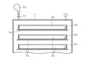
例えば、従来錠剤を真空乾燥する場合には、打錠工程で打錠された被乾燥物(錠剤)は図5で示すように大容量の容器(例えば缶)2へ投入され、この状態で乾燥工程に運ばれる。乾燥処理前において、被乾燥物3である錠剤群は容器2から定容量の布袋2aに定量ずつ小分けされ、布袋2a内に投入されたままの状態でトレイ2b(図6)に収容され、トレイ2bと適合して所定厚みになるように扁平に整形される。
図6で示すように、バルブ11を介して真空ポンプ10が設置された真空室1内には、棚1aが多段状に形成されており、各棚1aに錠剤入りの布袋2aを収容したトレイ2bをそれぞれ載せ、手前側の図示しない扉を閉めて真空室1を密閉し、真空ポンプ10により真空室1内を30Pa程度の真空状態(真空度)に保ち所定時間(5h程度〜15h)かけて乾燥させる。乾燥効率を高めるため、図示しない加熱手段により真空室1内を加熱する場合もある。
For example, when a conventional tablet is vacuum-dried, an object to be dried (tablet) compressed in the tableting process is put into a large-capacity container (for example, can) 2 as shown in FIG. Taken to the process. Prior to the drying treatment, the tablet group as the material to be dried 3 is subdivided from the
As shown in FIG. 6,
従来の真空乾燥方法では、乾燥処理前に大容量の容器2から小容量の布袋2aに小分けした後、トレイ2bに収容して布袋2aごと扁平に整形するので、乾燥処理前の作業に手間が掛かるほか、乾燥処理後は瓶詰め包装等のため布袋2aから取り出さなければならないので、乾燥処理後においても手間が掛かった。
また、布袋2aの詰め替え整形や布袋2aからの取り出しのため、錠剤相互の接触頻度が高く、錠剤等の表面品質を低下させるおそれがあった。
In the conventional vacuum drying method, the large-
Further, because the refill shaping of the
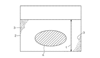
前述の問題を解消するためには、図5のように打錠後に容器2へ投入された状態のままで乾燥させるのが好ましいが、比較的大容量の容器2へ投入された錠剤や粉粒体等の被乾燥物3は、積層厚tが厚く乾燥効率が低下する。
発明者の実験によれば、容器2の周壁とその近傍及び上面とその近傍では錠剤相互間の隙間が大きく、水蒸気が上昇し易いため比較的乾燥効率が良好であるが、容器2がSUSの缶であって、被乾燥物3が錠径8mm,錠厚2.5mm程度の錠剤である場合、図5の細斜線で示す領域aでは、容器2の周壁及び上面の近傍の領域と比べ10〜16%程度乾燥効率が悪いことが判明した。
In order to solve the above-mentioned problem, it is preferable to dry the
According to the inventor's experiment, the peripheral wall of the
本発明の目的は、比較的大容量の容器2を使用した場合でも、より効率的に乾燥させることができる錠・粉粒体の真空乾燥方法を提供することにある。
An object of the present invention is to provide a vacuum drying method for tablets and granules that can be more efficiently dried even when a
本発明に係る第1の錠・粉粒体の真空乾燥方法は、前述の課題を解決するため、錠剤又は粉粒体からなる被乾燥物3が投入された上部開口の容器2を真空室1内に収容し、真空室1内を真空状態に保ちながら前記容器2の被乾燥物3の積層内の下部領域にエアーを僅かにリークさせることを最も主要な特徴とするものである。
In order to solve the above-described problems, the first method of vacuum drying a tablet / powder according to the present invention is to place a
本発明に係る第2の錠・粉粒体の真空乾燥方法は、前述の課題を解決するため、錠剤又は粉粒体からなる被乾燥物3が投入された上部開口の容器2を真空室1内に収容し、真空室1内を真空状態に保ちながら、前記容器2の被乾燥物3の積層内に上下方向に沿って設置したガイド部材4により水蒸気を上方にガイドさせることを最も主要な特徴とするものである。
In order to solve the above-described problems, the second method for vacuum drying a tablet / powder according to the present invention is to place a
本発明に係る第1の錠・粉粒体の真空乾燥方法によれば、真空状態で被乾燥物3から分離した水蒸気が、被乾燥物の積層内の株領域へリークされたエアーにより上方へ押し上げられるので乾燥が促進される。したがって、容器2が比較的大容量であっても効率的に乾燥される。
According to the first method for vacuum drying a tablet / powder according to the present invention, the water vapor separated from the material to be dried 3 in the vacuum state is upward due to the air leaked to the stock region in the layer of the material to be dried. Drying is promoted because it is pushed up. Therefore, even if the
本発明に係る第2の錠・粉粒体の真空乾燥方法によれば、被乾燥物3の積層内に上下方向に沿って設置したガイド部材4により、当該ガイド部材4の近傍では被乾燥物3の密度が小さくなり被乾燥物3相互間の隙間が大きくなるので、真空状態で被乾燥物3から発生した水蒸気がガイド部材4により上方へガイドされ、乾燥が促進される。したがって、容器が比較的大容量であっても効率的に乾燥する。
According to the vacuum drying method of the second tablet / powder according to the present invention, the material to be dried is provided in the vicinity of the
第1実施形態
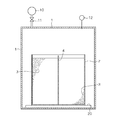
図1は、本発明に係る真空乾燥方法の第1実施形態を実施するための装置の断面図である。
手前側に図示しない扉を有する真空室1には、バルブ11を介して真空ポンプ10が設けられ、内部の真空度を計測する真空計12が設置されている。真空室1内には、台20上にステンレス製の円筒缶状の容器2が搬入されており、この容器2内には錠剤である被乾燥物3が投入されている。
真空室1には、先端部が容器2内の被乾燥物3の積層内の下部領域(容器2の内底部の中央領域)に達するように、リークチューブ5が差込み状態に設置されており、リークチューブ5の真空室1から外側に突き出した部分にはリークバルブ50とフィルタ51が設置されている。
リークチューブ5はフレキシブルチューブであり、先端部を上方に上げた状態に曲げ、この状態で被乾燥物3が投入された容器2を真空室1内に搬入し、その後リークチューブ5の先端部を被乾燥物3の積層内に差し込んで使用できるようになっている。
First Embodiment FIG. 1 is a cross-sectional view of an apparatus for carrying out a first embodiment of a vacuum drying method according to the present invention.
In a
In the
The
図1の装置により真空乾燥を行うには、被乾燥物3が投入された容器2を真空室1内に搬入し、リークチューブ5の先端部を図のように容器2の内底部中央の領域に差込み、真空室1の図示しない扉を閉めて密閉し、真空ポンプ10を作動させて真空室1内を真空脱気する。真空室1内が所定の真空度(例えば30Pa程度)に達したならば、リークバルブ50を僅かに開き外気を僅かに導入してリークさせ、真空室1内の真空度が90から130Pa程度になるように調整する。この状態で5時間程度運転する。リーク時の最適な真空度は110Pa程度である。
このように真空室1内を所定の真空状態に保った状態で、容器2内の被乾燥物3の積層内の下部領域にエアーを少しずつリークさせると、被乾燥物3から分離した水蒸気がリークされたエアーにより被乾燥物3相互の間で押し上げられるので、被乾燥物3が密集していても乾燥が促進される。
In order to perform vacuum drying using the apparatus of FIG. 1, the
When air is gradually leaked to the lower region in the stack of the objects to be dried 3 in the
実施例1
SUSの15L缶(φ270mm×h262mm)からなる容器2内に、錠径8mm,錠厚2.5mmであって水分含有率2.50%の錠剤を12kg投入し、リークチューブ5を使用せず真空室1内を30Paに保って5時間の乾燥を5回試みた(比較例1)。
他方、同様な条件で真空室1内が30Paに達した後、リークバルブ50を開いて容器2の内底部中央の領域にエアーをリークさせ、真空室1内を110Pa程度に保って5時間の乾燥を5回試みた(実施例1)。
両者の乾燥減量を測定したところ、比較例1では−1.152〜−1.160%であったのに対し、実施例1では−1.256〜−1.276%であり、実施例では比較例に対して9〜10%乾燥率が向上した。
Example 1
12 kg of tablets with a tablet diameter of 8 mm, a tablet thickness of 2.5 mm, and a moisture content of 2.50% were put into a
On the other hand, after the inside of the
When the loss on drying of both was measured, it was -1.152 to -1.160% in Comparative Example 1, whereas it was -1.256 to -1.276% in Example 1, and in the Example, Compared to the comparative example, the drying rate was improved by 9 to 10%.
第2実施形態
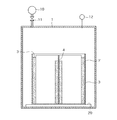
図2は、本発明に係る真空乾燥方法の第2実施形態を実施するための装置の断面図である。
真空室1には、バルブ11を介して真空ポンプ10が設置されているほか、真空計12が設置されている。
真空室1内の台20上には、内部に錠剤からなる被乾燥物3が投入された同様な容器2が搬入されている。容器2内には、当該容器2の内径よりもやや幅が狭くかつ当該容器2内を連続した二つの領域に区分するように、仕切状のガイド部材4が上下方向に沿って挿入され、真空室1内が真空状態になると被乾燥物3から分離した水蒸気がガイド部材4により上方にガイドされるように構成されている。ガイド部材4の材質は特に問わないが、この実施形態では肉厚0.5mm,高さ260mm,幅240mmのSUS板である。
Second Embodiment FIG. 2 is a cross-sectional view of an apparatus for carrying out a second embodiment of the vacuum drying method according to the present invention.
In the
On the table 20 in the
図2の装置により真空乾燥を行うには、図2のように被乾燥物3が投入された容器2内にガイド部材4を上下方向に設置し、真空ポンプ10により真空室1内を真空脱気して30Pa程度の真空度に保ち、所定時間(5時間程度)運転する。被乾燥物3の積層内に上下方向に沿って設置されたガイド部材4により、当該ガイド部材4の近傍では被乾燥物3の密度が小さくなり被乾燥物3相互間の隙間が大きくなるので、真空状態で被乾燥物3から発生した水蒸気が上方へ引っ張られるようにガイドされ、乾燥が促進される。したがって、容器が比較的大容量であっても効率的に乾燥する。
In order to perform vacuum drying with the apparatus of FIG. 2, the
実施例2
SUSの15L缶(φ270mm×h262mm)からなる容器2内に、錠径8mm,錠厚2.5mmであって水分含有率2.42%の錠剤を12kg投入し、ガイド部材4を使用せず真空室1内を30Paに保って5時間の乾燥を5回試みた(比較例2)。
他方、同様な条件で容器2内に仕切板状のガイド部材4を設置し、真空室1内を30Pa程度の真空度に保って5時間の乾燥を5回試みた(実施例2)。
両者の乾燥減量を測定したところ、比較例2では−1.115〜−1.117%であったのに対し、実施例2では−1.156〜−1.162%であり、実施例では比較例に対して3.6〜4%乾燥率が向上した。
Example 2
12 kg of tablets with a tablet diameter of 8 mm, a tablet thickness of 2.5 mm, and a moisture content of 2.42% were placed in a
On the other hand, a partition plate-shaped
When the loss on drying of both was measured, it was -1.115 to -1.117% in Comparative Example 2, whereas it was -1.156 to -1.162% in Example 2, and in the Example, The drying rate was improved by 3.6 to 4% relative to the comparative example.
第3実施形態
図3は、本発明に係る真空乾燥方法の第3実施形態を実施するための装置の断面図である。
この装置において、ガイド部材4は平面ほぼ十字状に形成した仕切状の部材であり、容器2内はガイド部材4により互いに連続する四つの領域に区分される。他の構成は図2の装置と同様である。
この装置を使用した乾燥方法では、ガイド部材4によって容器2内が四つの連続した領域に区分され、ガイド部材4と被乾燥物3との接触面積が図2の場合に比べほぼ倍になるので、その分乾燥効率がさらに向上する。
Third Embodiment FIG. 3 is a sectional view of an apparatus for carrying out a third embodiment of the vacuum drying method according to the present invention.
In this apparatus, the
In the drying method using this apparatus, the inside of the
実施例3
実施例2の場合と同様に、SUSの15L缶(φ270mm×h262mm)からなる容器2内に、錠径8mm,錠厚2.5mmであって水分含有率2.42%の錠剤を12kg投入し、図3で示すような平面十字状に組み合わせたSUS板(肉厚0.5mm,各幅240mm,高さ260mm)からなるガイド部材4を使用し、真空室1内を30Paに保って5時間の乾燥を5回試みた(実施例3)。
その乾燥減量を測定したところ、−1.1485〜−1.163%であり、実施例3では比較例2に対して3〜4.1%乾燥効率が向上した。
Example 3
As in the case of Example 2, 12 kg of tablets having a tablet diameter of 8 mm, a tablet thickness of 2.5 mm, and a moisture content of 2.42% were put into a
When the loss on drying was measured, it was -1.1485 to -1.163%, and in Example 3, the drying efficiency was improved by 3 to 4.1% compared to Comparative Example 2.
第4実施形態
図4は、本発明に係る真空乾燥方法の第4実施形態を実施するための装置の断面図である。
この装置において、ガイド部材4はφ90mm,肉厚0.5mm,高さ260mmのSUSの円筒であり、容器2内はガイド部材4により互いに独立した内外二つ領域に区分される。他の構成は図2の装置と同様である。
この装置を使用した乾燥方法では、ガイド部材4と被乾燥物との接触面積が図2の場合と比べて20%弱増大することと、円筒状のガイド部材4による煙突作用と類似した作用により真空下で被乾燥物3から分離した水蒸気が効率的に押し上げられるので、実験によれば図3の実施形態とほぼ同等の効果を奏する。
4th Embodiment FIG. 4: is sectional drawing of the apparatus for enforcing 4th Embodiment of the vacuum-drying method which concerns on this invention.
In this apparatus, the
In the drying method using this apparatus, the contact area between the
前記説明は被乾燥物3が錠剤である場合についてのみ説明したが、被乾燥物が粉粒体である場合にも同様に実施することができるものである。
本発明において、真空室1内を所定の真空状態に保った状態でガイド部材4を使用しながら容器2の内部にエアーをリークすれば、乾燥効率をさらに高めることができる。また、ガイド部材4は容器2内に被乾燥物3を投入した後に挿入しても実施することができるほか、あらかじめガイド部材4を容器2内に設置しても実施することができる。
真空室1内では蒸発熱が奪われて温度が低下するので、容器2内に設置するガイド部材4は、例えば内空部(外部に開放されていない)厚みが10mm前後の中空板や断熱材のように、急激に温度低下しない材質の物を使用するのが好ましい。
Although the said description demonstrated only the case where the to-
In the present invention, if air is leaked into the
Since the evaporation heat is taken away in the
1 真空室
1a 棚
10 真空ポンプ
11 バルブ
12 真空計
2 容器
2a 布袋
2b トレイ
20 台
3 被乾燥物
4 ガイド部材
5 リークチューブ
50 リークバルブ
51 フィルタ
DESCRIPTION OF
Claims (4)
Priority Applications (1)
| Application Number | Priority Date | Filing Date | Title |
|---|---|---|---|
| JP2004110072A JP2005291656A (en) | 2004-04-02 | 2004-04-02 | Vacuum drying method for tablets and granules |
Applications Claiming Priority (1)
| Application Number | Priority Date | Filing Date | Title |
|---|---|---|---|
| JP2004110072A JP2005291656A (en) | 2004-04-02 | 2004-04-02 | Vacuum drying method for tablets and granules |
Publications (1)
| Publication Number | Publication Date |
|---|---|
| JP2005291656A true JP2005291656A (en) | 2005-10-20 |
Family
ID=35324775
Family Applications (1)
| Application Number | Title | Priority Date | Filing Date |
|---|---|---|---|
| JP2004110072A Pending JP2005291656A (en) | 2004-04-02 | 2004-04-02 | Vacuum drying method for tablets and granules |
Country Status (1)
| Country | Link |
|---|---|
| JP (1) | JP2005291656A (en) |
Cited By (2)
| Publication number | Priority date | Publication date | Assignee | Title |
|---|---|---|---|---|
| JP2012197979A (en) * | 2011-03-22 | 2012-10-18 | Shin Ootsuka Kk | Device for drying workpiece, and device for cleaning and drying workpiece |
| US11815433B2 (en) | 2019-05-03 | 2023-11-14 | Shimadzu Corporation | Adsorption apparatus and chemiluminescence type nitrogen oxide concentration meter |
-
2004
- 2004-04-02 JP JP2004110072A patent/JP2005291656A/en active Pending
Cited By (2)
| Publication number | Priority date | Publication date | Assignee | Title |
|---|---|---|---|---|
| JP2012197979A (en) * | 2011-03-22 | 2012-10-18 | Shin Ootsuka Kk | Device for drying workpiece, and device for cleaning and drying workpiece |
| US11815433B2 (en) | 2019-05-03 | 2023-11-14 | Shimadzu Corporation | Adsorption apparatus and chemiluminescence type nitrogen oxide concentration meter |
Similar Documents
| Publication | Publication Date | Title |
|---|---|---|
| US20170275075A1 (en) | Vacuum Sealed Container for Perishable and Non Perishable Goods | |
| JP2020527688A5 (en) | ||
| US20140075889A1 (en) | System and method for storing items | |
| CN201276270Y (en) | Air conditioning fresh-keeping box | |
| JP2005291656A (en) | Vacuum drying method for tablets and granules | |
| CN208278615U (en) | A kind of agricultural product logistics transport case | |
| CN108146852A (en) | Shockproof transport case | |
| CN207341354U (en) | A kind of cellular-type self-heating meal box | |
| JP4042394B2 (en) | Manufacturing method of block-like freeze-dried foods | |
| CN111153049A (en) | Fruit and vegetable storage and transportation integrated packing box | |
| CN207823081U (en) | A kind of sample storing boxes | |
| CN203258950U (en) | Refrigerator | |
| CN102475126A (en) | Vacuum refrigeration fresh-keeping method for fruits and vegetables | |
| CN216735404U (en) | Freeze-drying reagent bottle storage box and storage box containing box | |
| CN206032098U (en) | Fresh -keeping case device of harmless transportation of agaricus bisporus | |
| CN216592709U (en) | Continuous feeding and discharging device of freeze-drying equipment | |
| CN207312217U (en) | A kind of Medicines cold chain transportation case | |
| ES2907267T3 (en) | Process for manufacturing a refrigeration and/or freezing device | |
| CN206278415U (en) | Tape roll packing box structure | |
| CN207465172U (en) | A kind of network transformer efficient storage device | |
| CN214980914U (en) | Wine bottle production is with effectual strorage device that prevents damp | |
| KR200410098Y1 (en) | Food packaging | |
| CN220119685U (en) | Bottom-drawing hollowed-out freeze-drying tray | |
| CN214297079U (en) | Packing box with separated storage | |
| CN104229187A (en) | Food seasoning evacuating device |