JP2005291628A - Helium re-liquefying device, purifier, valve mechanism, and condenser - Google Patents
Helium re-liquefying device, purifier, valve mechanism, and condenser Download PDFInfo
- Publication number
- JP2005291628A JP2005291628A JP2004107890A JP2004107890A JP2005291628A JP 2005291628 A JP2005291628 A JP 2005291628A JP 2004107890 A JP2004107890 A JP 2004107890A JP 2004107890 A JP2004107890 A JP 2004107890A JP 2005291628 A JP2005291628 A JP 2005291628A
- Authority
- JP
- Japan
- Prior art keywords
- helium
- purifier
- valve
- condenser
- storage tank
- Prior art date
- Legal status (The legal status is an assumption and is not a legal conclusion. Google has not performed a legal analysis and makes no representation as to the accuracy of the status listed.)
- Pending
Links
- 239000001307 helium Substances 0.000 title claims abstract description 184
- 229910052734 helium Inorganic materials 0.000 title claims abstract description 184
- SWQJXJOGLNCZEY-UHFFFAOYSA-N helium atom Chemical compound [He] SWQJXJOGLNCZEY-UHFFFAOYSA-N 0.000 title claims abstract description 180
- 230000007246 mechanism Effects 0.000 title claims description 15
- 239000007789 gas Substances 0.000 claims abstract description 92
- 238000001816 cooling Methods 0.000 claims abstract description 58
- 239000012535 impurity Substances 0.000 claims abstract description 53
- 239000007788 liquid Substances 0.000 claims abstract description 43
- 239000012530 fluid Substances 0.000 claims abstract description 16
- 238000013459 approach Methods 0.000 claims description 5
- 238000012545 processing Methods 0.000 claims description 5
- 230000007423 decrease Effects 0.000 claims description 2
- 239000010419 fine particle Substances 0.000 claims 1
- 238000010438 heat treatment Methods 0.000 claims 1
- 150000002371 helium Chemical class 0.000 abstract description 4
- IJGRMHOSHXDMSA-UHFFFAOYSA-N Atomic nitrogen Chemical compound N#N IJGRMHOSHXDMSA-UHFFFAOYSA-N 0.000 description 18
- RYGMFSIKBFXOCR-UHFFFAOYSA-N Copper Chemical compound [Cu] RYGMFSIKBFXOCR-UHFFFAOYSA-N 0.000 description 10
- 238000005259 measurement Methods 0.000 description 10
- 238000005192 partition Methods 0.000 description 10
- QVGXLLKOCUKJST-UHFFFAOYSA-N atomic oxygen Chemical compound [O] QVGXLLKOCUKJST-UHFFFAOYSA-N 0.000 description 9
- 229910052757 nitrogen Inorganic materials 0.000 description 9
- 239000001301 oxygen Substances 0.000 description 9
- 229910052760 oxygen Inorganic materials 0.000 description 9
- 238000011084 recovery Methods 0.000 description 9
- 229910052802 copper Inorganic materials 0.000 description 8
- 239000010949 copper Substances 0.000 description 8
- 239000000463 material Substances 0.000 description 8
- 239000004005 microsphere Substances 0.000 description 8
- 238000012546 transfer Methods 0.000 description 8
- 238000007710 freezing Methods 0.000 description 7
- 230000008014 freezing Effects 0.000 description 7
- 241000238366 Cephalopoda Species 0.000 description 4
- 238000000034 method Methods 0.000 description 4
- 239000011859 microparticle Substances 0.000 description 3
- 238000005057 refrigeration Methods 0.000 description 3
- 101100023111 Schizosaccharomyces pombe (strain 972 / ATCC 24843) mfc1 gene Proteins 0.000 description 2
- 210000004556 brain Anatomy 0.000 description 2
- 238000001514 detection method Methods 0.000 description 2
- 238000010586 diagram Methods 0.000 description 2
- 230000007177 brain activity Effects 0.000 description 1
- 239000000919 ceramic Substances 0.000 description 1
- 238000005516 engineering process Methods 0.000 description 1
- 239000008187 granular material Substances 0.000 description 1
- 230000005484 gravity Effects 0.000 description 1
- 230000005389 magnetism Effects 0.000 description 1
- 239000002245 particle Substances 0.000 description 1
- 230000002093 peripheral effect Effects 0.000 description 1
- 230000001105 regulatory effect Effects 0.000 description 1
- 230000009897 systematic effect Effects 0.000 description 1
Images




Classifications
-
- F—MECHANICAL ENGINEERING; LIGHTING; HEATING; WEAPONS; BLASTING
- F25—REFRIGERATION OR COOLING; COMBINED HEATING AND REFRIGERATION SYSTEMS; HEAT PUMP SYSTEMS; MANUFACTURE OR STORAGE OF ICE; LIQUEFACTION SOLIDIFICATION OF GASES
- F25B—REFRIGERATION MACHINES, PLANTS OR SYSTEMS; COMBINED HEATING AND REFRIGERATION SYSTEMS; HEAT PUMP SYSTEMS
- F25B43/00—Arrangements for separating or purifying gases or liquids; Arrangements for vaporising the residuum of liquid refrigerant, e.g. by heat
- F25B43/003—Filters
-
- F—MECHANICAL ENGINEERING; LIGHTING; HEATING; WEAPONS; BLASTING
- F25—REFRIGERATION OR COOLING; COMBINED HEATING AND REFRIGERATION SYSTEMS; HEAT PUMP SYSTEMS; MANUFACTURE OR STORAGE OF ICE; LIQUEFACTION SOLIDIFICATION OF GASES
- F25J—LIQUEFACTION, SOLIDIFICATION OR SEPARATION OF GASES OR GASEOUS OR LIQUEFIED GASEOUS MIXTURES BY PRESSURE AND COLD TREATMENT OR BY BRINGING THEM INTO THE SUPERCRITICAL STATE
- F25J1/00—Processes or apparatus for liquefying or solidifying gases or gaseous mixtures
- F25J1/006—Processes or apparatus for liquefying or solidifying gases or gaseous mixtures characterised by the refrigerant fluid used
- F25J1/0062—Light or noble gases, mixtures thereof
- F25J1/0065—Helium
-
- F—MECHANICAL ENGINEERING; LIGHTING; HEATING; WEAPONS; BLASTING
- F25—REFRIGERATION OR COOLING; COMBINED HEATING AND REFRIGERATION SYSTEMS; HEAT PUMP SYSTEMS; MANUFACTURE OR STORAGE OF ICE; LIQUEFACTION SOLIDIFICATION OF GASES
- F25J—LIQUEFACTION, SOLIDIFICATION OR SEPARATION OF GASES OR GASEOUS OR LIQUEFIED GASEOUS MIXTURES BY PRESSURE AND COLD TREATMENT OR BY BRINGING THEM INTO THE SUPERCRITICAL STATE
- F25J1/00—Processes or apparatus for liquefying or solidifying gases or gaseous mixtures
- F25J1/02—Processes or apparatus for liquefying or solidifying gases or gaseous mixtures requiring the use of refrigeration, e.g. of helium or hydrogen ; Details and kind of the refrigeration system used; Integration with other units or processes; Controlling aspects of the process
- F25J1/0243—Start-up or control of the process; Details of the apparatus used; Details of the refrigerant compression system used
- F25J1/0244—Operation; Control and regulation; Instrumentation
- F25J1/0245—Different modes, i.e. 'runs', of operation; Process control
- F25J1/0249—Controlling refrigerant inventory, i.e. composition or quantity
- F25J1/025—Details related to the refrigerant production or treatment, e.g. make-up supply from feed gas itself
-
- F—MECHANICAL ENGINEERING; LIGHTING; HEATING; WEAPONS; BLASTING
- F25—REFRIGERATION OR COOLING; COMBINED HEATING AND REFRIGERATION SYSTEMS; HEAT PUMP SYSTEMS; MANUFACTURE OR STORAGE OF ICE; LIQUEFACTION SOLIDIFICATION OF GASES
- F25J—LIQUEFACTION, SOLIDIFICATION OR SEPARATION OF GASES OR GASEOUS OR LIQUEFIED GASEOUS MIXTURES BY PRESSURE AND COLD TREATMENT OR BY BRINGING THEM INTO THE SUPERCRITICAL STATE
- F25J1/00—Processes or apparatus for liquefying or solidifying gases or gaseous mixtures
- F25J1/02—Processes or apparatus for liquefying or solidifying gases or gaseous mixtures requiring the use of refrigeration, e.g. of helium or hydrogen ; Details and kind of the refrigeration system used; Integration with other units or processes; Controlling aspects of the process
- F25J1/0243—Start-up or control of the process; Details of the apparatus used; Details of the refrigerant compression system used
- F25J1/0257—Construction and layout of liquefaction equipments, e.g. valves, machines
- F25J1/0275—Construction and layout of liquefaction equipments, e.g. valves, machines adapted for special use of the liquefaction unit, e.g. portable or transportable devices
- F25J1/0276—Laboratory or other miniature devices
-
- F—MECHANICAL ENGINEERING; LIGHTING; HEATING; WEAPONS; BLASTING
- F25—REFRIGERATION OR COOLING; COMBINED HEATING AND REFRIGERATION SYSTEMS; HEAT PUMP SYSTEMS; MANUFACTURE OR STORAGE OF ICE; LIQUEFACTION SOLIDIFICATION OF GASES
- F25J—LIQUEFACTION, SOLIDIFICATION OR SEPARATION OF GASES OR GASEOUS OR LIQUEFIED GASEOUS MIXTURES BY PRESSURE AND COLD TREATMENT OR BY BRINGING THEM INTO THE SUPERCRITICAL STATE
- F25J3/00—Processes or apparatus for separating the constituents of gaseous or liquefied gaseous mixtures involving the use of liquefaction or solidification
- F25J3/08—Separating gaseous impurities from gases or gaseous mixtures or from liquefied gases or liquefied gaseous mixtures
-
- F—MECHANICAL ENGINEERING; LIGHTING; HEATING; WEAPONS; BLASTING
- F25—REFRIGERATION OR COOLING; COMBINED HEATING AND REFRIGERATION SYSTEMS; HEAT PUMP SYSTEMS; MANUFACTURE OR STORAGE OF ICE; LIQUEFACTION SOLIDIFICATION OF GASES
- F25B—REFRIGERATION MACHINES, PLANTS OR SYSTEMS; COMBINED HEATING AND REFRIGERATION SYSTEMS; HEAT PUMP SYSTEMS
- F25B9/00—Compression machines, plants or systems, in which the refrigerant is air or other gas of low boiling point
- F25B9/002—Compression machines, plants or systems, in which the refrigerant is air or other gas of low boiling point characterised by the refrigerant
-
- F—MECHANICAL ENGINEERING; LIGHTING; HEATING; WEAPONS; BLASTING
- F25—REFRIGERATION OR COOLING; COMBINED HEATING AND REFRIGERATION SYSTEMS; HEAT PUMP SYSTEMS; MANUFACTURE OR STORAGE OF ICE; LIQUEFACTION SOLIDIFICATION OF GASES
- F25D—REFRIGERATORS; COLD ROOMS; ICE-BOXES; COOLING OR FREEZING APPARATUS NOT OTHERWISE PROVIDED FOR
- F25D19/00—Arrangement or mounting of refrigeration units with respect to devices or objects to be refrigerated, e.g. infrared detectors
-
- F—MECHANICAL ENGINEERING; LIGHTING; HEATING; WEAPONS; BLASTING
- F25—REFRIGERATION OR COOLING; COMBINED HEATING AND REFRIGERATION SYSTEMS; HEAT PUMP SYSTEMS; MANUFACTURE OR STORAGE OF ICE; LIQUEFACTION SOLIDIFICATION OF GASES
- F25J—LIQUEFACTION, SOLIDIFICATION OR SEPARATION OF GASES OR GASEOUS OR LIQUEFIED GASEOUS MIXTURES BY PRESSURE AND COLD TREATMENT OR BY BRINGING THEM INTO THE SUPERCRITICAL STATE
- F25J2205/00—Processes or apparatus using other separation and/or other processing means
- F25J2205/20—Processes or apparatus using other separation and/or other processing means using solidification of components
-
- F—MECHANICAL ENGINEERING; LIGHTING; HEATING; WEAPONS; BLASTING
- F25—REFRIGERATION OR COOLING; COMBINED HEATING AND REFRIGERATION SYSTEMS; HEAT PUMP SYSTEMS; MANUFACTURE OR STORAGE OF ICE; LIQUEFACTION SOLIDIFICATION OF GASES
- F25J—LIQUEFACTION, SOLIDIFICATION OR SEPARATION OF GASES OR GASEOUS OR LIQUEFIED GASEOUS MIXTURES BY PRESSURE AND COLD TREATMENT OR BY BRINGING THEM INTO THE SUPERCRITICAL STATE
- F25J2215/00—Processes characterised by the type or other details of the product stream
- F25J2215/30—Helium
-
- F—MECHANICAL ENGINEERING; LIGHTING; HEATING; WEAPONS; BLASTING
- F25—REFRIGERATION OR COOLING; COMBINED HEATING AND REFRIGERATION SYSTEMS; HEAT PUMP SYSTEMS; MANUFACTURE OR STORAGE OF ICE; LIQUEFACTION SOLIDIFICATION OF GASES
- F25J—LIQUEFACTION, SOLIDIFICATION OR SEPARATION OF GASES OR GASEOUS OR LIQUEFIED GASEOUS MIXTURES BY PRESSURE AND COLD TREATMENT OR BY BRINGING THEM INTO THE SUPERCRITICAL STATE
- F25J2245/00—Processes or apparatus involving steps for recycling of process streams
- F25J2245/90—Processes or apparatus involving steps for recycling of process streams the recycled stream being boil-off gas from storage
-
- F—MECHANICAL ENGINEERING; LIGHTING; HEATING; WEAPONS; BLASTING
- F25—REFRIGERATION OR COOLING; COMBINED HEATING AND REFRIGERATION SYSTEMS; HEAT PUMP SYSTEMS; MANUFACTURE OR STORAGE OF ICE; LIQUEFACTION SOLIDIFICATION OF GASES
- F25J—LIQUEFACTION, SOLIDIFICATION OR SEPARATION OF GASES OR GASEOUS OR LIQUEFIED GASEOUS MIXTURES BY PRESSURE AND COLD TREATMENT OR BY BRINGING THEM INTO THE SUPERCRITICAL STATE
- F25J2270/00—Refrigeration techniques used
- F25J2270/90—External refrigeration, e.g. conventional closed-loop mechanical refrigeration unit using Freon or NH3, unspecified external refrigeration
-
- F—MECHANICAL ENGINEERING; LIGHTING; HEATING; WEAPONS; BLASTING
- F25—REFRIGERATION OR COOLING; COMBINED HEATING AND REFRIGERATION SYSTEMS; HEAT PUMP SYSTEMS; MANUFACTURE OR STORAGE OF ICE; LIQUEFACTION SOLIDIFICATION OF GASES
- F25J—LIQUEFACTION, SOLIDIFICATION OR SEPARATION OF GASES OR GASEOUS OR LIQUEFIED GASEOUS MIXTURES BY PRESSURE AND COLD TREATMENT OR BY BRINGING THEM INTO THE SUPERCRITICAL STATE
- F25J2270/00—Refrigeration techniques used
- F25J2270/90—External refrigeration, e.g. conventional closed-loop mechanical refrigeration unit using Freon or NH3, unspecified external refrigeration
- F25J2270/912—Liquefaction cycle of a low-boiling (feed) gas in a cryocooler, i.e. in a closed-loop refrigerator
-
- F—MECHANICAL ENGINEERING; LIGHTING; HEATING; WEAPONS; BLASTING
- F25—REFRIGERATION OR COOLING; COMBINED HEATING AND REFRIGERATION SYSTEMS; HEAT PUMP SYSTEMS; MANUFACTURE OR STORAGE OF ICE; LIQUEFACTION SOLIDIFICATION OF GASES
- F25J—LIQUEFACTION, SOLIDIFICATION OR SEPARATION OF GASES OR GASEOUS OR LIQUEFIED GASEOUS MIXTURES BY PRESSURE AND COLD TREATMENT OR BY BRINGING THEM INTO THE SUPERCRITICAL STATE
- F25J2280/00—Control of the process or apparatus
- F25J2280/30—Control of a discontinuous or intermittent ("batch") process
-
- F—MECHANICAL ENGINEERING; LIGHTING; HEATING; WEAPONS; BLASTING
- F25—REFRIGERATION OR COOLING; COMBINED HEATING AND REFRIGERATION SYSTEMS; HEAT PUMP SYSTEMS; MANUFACTURE OR STORAGE OF ICE; LIQUEFACTION SOLIDIFICATION OF GASES
- F25J—LIQUEFACTION, SOLIDIFICATION OR SEPARATION OF GASES OR GASEOUS OR LIQUEFIED GASEOUS MIXTURES BY PRESSURE AND COLD TREATMENT OR BY BRINGING THEM INTO THE SUPERCRITICAL STATE
- F25J2290/00—Other details not covered by groups F25J2200/00 - F25J2280/00
- F25J2290/62—Details of storing a fluid in a tank
Landscapes
- Engineering & Computer Science (AREA)
- Physics & Mathematics (AREA)
- Mechanical Engineering (AREA)
- Thermal Sciences (AREA)
- General Engineering & Computer Science (AREA)
- Health & Medical Sciences (AREA)
- Clinical Laboratory Science (AREA)
- Chemical & Material Sciences (AREA)
- Analytical Chemistry (AREA)
- Power Engineering (AREA)
- Separation By Low-Temperature Treatments (AREA)
Abstract
Description
本発明は、極低温の液体ヘリウムを貯留する貯留槽で気化したヘリウムを回収し、再液化させて貯留槽に返送するためのヘリウム再液化処理に関し、特に、このようなヘリウム再液化処理に使用され得る精製器、ヘリウム再液化装置、弁機構および凝縮器に関する。 The present invention relates to helium reliquefaction processing for recovering helium vaporized in a storage tank storing cryogenic liquid helium, reliquefying it, and returning it to the storage tank, and in particular, used for such helium reliquefaction processing. To purifiers, helium reliquefaction devices, valve mechanisms and condensers that can be made.
従来から、生体磁気計測システム、心磁計、NMR装置、MRI装置等といった計測器等の冷却には、極低温(およそ4K)の液体ヘリウムが用いられている。かかる液体ヘリウムは、希少な資源であると共に比較的高価なものであることから、冷却過程で気化したヘリウムガスを大気に開放してしまうのは好ましいことではない。このため、ヘリウムガスの再利用を可能とするための技術として、極低温の液体ヘリウムを貯留する貯留槽で気化したヘリウムを回収し、再液化させて貯留槽に返送するヘリウム再液化装置が知られている(例えば、特許文献1および特許文献2参照。) Conventionally, cryogenic (approximately 4K) liquid helium has been used to cool measuring instruments such as biomagnetic measurement systems, magnetocardiographs, NMR apparatuses, and MRI apparatuses. Since such liquid helium is a scarce resource and relatively expensive, it is not preferable to release the helium gas vaporized in the cooling process to the atmosphere. For this reason, a helium re-liquefaction device that recovers helium vaporized in a storage tank storing cryogenic liquid helium, re-liquefies it, and returns it to the storage tank is known as a technology for enabling reuse of helium gas. (See, for example, Patent Document 1 and Patent Document 2.)
上述のヘリウム再液化装置は、ヘリウムをおよそ4Kにまで冷却可能なギフォードマクマホンサイクル冷凍機(以下、「GM冷凍機」という)と、このGM冷凍機に接続された凝縮器と、貯留槽から回収されたヘリウムガス中の不純物を冷却・固化させて捕捉する精製器とを含む。貯留槽で発生した低温(およそ4〜10K)のヘリウムガスは、凝縮器に送られ、極低温の液体ヘリウムへと再液化させられる。また、貯留槽で発生した比較的高温(およそ300K)のヘリウムガスは、循環ポンプによって回収されて精製器に導入され、そこでヘリウムガスから窒素や酸素といった不純物が除去される。精製器を通過したヘリウムガスは、GM冷凍機によって段階的に冷却された後、凝縮器に送られ、そこで極低温の液体ヘリウムへと再液化させられる。 The above-mentioned helium reliquefaction apparatus is recovered from a Gifford McMahon cycle refrigerator (hereinafter referred to as “GM refrigerator”) capable of cooling helium to approximately 4K, a condenser connected to the GM refrigerator, and a storage tank. A purifier that cools and solidifies the impurities in the helium gas. The low-temperature (approximately 4 to 10 K) helium gas generated in the storage tank is sent to the condenser and re-liquefied into cryogenic liquid helium. Further, the relatively high temperature (approximately 300 K) helium gas generated in the storage tank is collected by a circulation pump and introduced into a purifier, where impurities such as nitrogen and oxygen are removed from the helium gas. The helium gas that has passed through the purifier is cooled stepwise by the GM refrigerator and then sent to the condenser where it is reliquefied into cryogenic liquid helium.
上述のようなヘリウム再液化処理に用いられる精製器は、ヘリウムガス中の不純物を確実に捕捉して、下流側への不純物の流出を抑制可能なものでなければならない。また、精製器が不純物によって閉塞し始めた場合には、不純物の下流側への流出を確実に抑制しながら、精製器から確実に不純物を除去する必要がある。更に、精製器から凝縮器へと不純物が流入するおそれもあるので、その不純物を下流側に流出させないために、低温環境下で確実に作動する弁機構が必要不可欠である。 The purifier used for the helium reliquefaction process as described above must be capable of reliably capturing impurities in the helium gas and suppressing the outflow of impurities downstream. Further, when the purifier starts to be blocked by impurities, it is necessary to reliably remove impurities from the purifier while reliably suppressing the outflow of impurities to the downstream side. Furthermore, since impurities may flow from the purifier to the condenser, a valve mechanism that operates reliably in a low temperature environment is indispensable to prevent the impurities from flowing downstream.
本発明は、上述の一つまたはそれ以上の問題点を解決することに向けられる。 The present invention is directed to overcoming one or more of the problems as set forth above.
本発明の精製器は、極低温の液体ヘリウムを貯留する貯留槽で気化したヘリウムを回収し、再液化させて貯留槽に返送するヘリウム再液化処理に使用される。この精製器は、貯留槽から回収されたヘリウムガス中の不純物を冷却・固化させて捕捉するものであり、精製器本体と、多孔質性の捕捉手段とを備える。捕捉手段は、ヘリウムガスの流通を許容すると共に当該ヘリウムガスと十分に接触するように構成されており、精製器本体の出口側(最下流側)に配置されると共に例えばGM冷凍機等の冷熱源に接続されている。この精製器によれば、貯留槽から回収されるヘリウムガス中の窒素や酸素といった不純物を冷却・固化させて確実に捕捉することが可能となる。この場合、精製器本体の入口から捕捉手段の入口までの距離をできるだけ長くするとよい。また、精製器本体は、その入口から捕捉手段の入口までの間に、蛇行流路を含むとよい。 The purifier of the present invention is used for a helium reliquefaction process in which helium vaporized in a storage tank storing cryogenic liquid helium is recovered, reliquefied, and returned to the storage tank. This purifier cools and solidifies the impurities in the helium gas collected from the storage tank, and includes a purifier body and porous trapping means. The trapping means is configured to allow the helium gas to flow and to be in sufficient contact with the helium gas, and is disposed on the outlet side (the most downstream side) of the purifier main body and, for example, cold heat such as a GM refrigerator. Connected to the source. According to this purifier, impurities such as nitrogen and oxygen in the helium gas recovered from the storage tank can be reliably captured by cooling and solidifying. In this case, the distance from the inlet of the purifier body to the inlet of the capturing means should be made as long as possible. Further, the purifier main body may include a meandering channel between the inlet and the inlet of the capturing means.
好ましくは、捕捉手段は、高密度に集合させられた多数の微小粒状体を含む。この場合、ヘリウムガス中の不純物は、冷熱源からの冷熱により冷却されて固化し、多数の微小な粒状体同士の間に形成される微小な隙間に確実に捕捉される。また、微小粒状体のサイズは、ヘリウムガスの流れ方向に沿って段階的に変化させられるとよい。 Preferably, the capturing means includes a large number of microparticles gathered at a high density. In this case, the impurities in the helium gas are cooled and solidified by the cold heat from the cold heat source, and are reliably trapped in the minute gaps formed between the many minute particles. Further, the size of the micro granular material may be changed stepwise along the flow direction of the helium gas.
本発明の他の精製器も、極低温の液体ヘリウムを貯留する貯留槽で気化したヘリウムを回収し、再液化させて貯留槽に返送するヘリウム再液化処理に使用される。この精製器は、貯留槽から回収されたヘリウムガス中の不純物を冷却・固化させて捕捉するものであり、例えばGM冷凍機等の冷熱源に接続された精製器本体と、精製器本体の内部に並設された複数の冷却室とを備える。互いに隣り合う冷却室同士は、ヘリウムガスが一方の冷却室の内壁に沿って流通してから他方の冷却室に流れ込むように連通されており、これにより、ヘリウムガスが流通する蛇行流路が形成される。また、精製器本体の軸方向における冷却室の寸法は、精製器本体の出口に近づくにつれて小さくなっている。 Another purifier of the present invention is also used for the helium reliquefaction process in which helium vaporized in a storage tank storing cryogenic liquid helium is recovered, reliquefied, and returned to the storage tank. This purifier cools and solidifies the impurities in the helium gas collected from the storage tank and captures it, for example, a purifier main body connected to a cooling heat source such as a GM refrigerator, and the inside of the purifier main body. And a plurality of cooling chambers arranged side by side. Adjacent cooling chambers communicate with each other so that helium gas flows along the inner wall of one cooling chamber and then flows into the other cooling chamber, thereby forming a meandering channel through which helium gas flows. Is done. Moreover, the dimension of the cooling chamber in the axial direction of the purifier main body becomes smaller as it approaches the outlet of the purifier main body.
このような精製器では、精製器本体におけるヘリウムガスの流路をより一層長くし、各冷却室の壁面等とヘリウムガスとが接触する確立を高めることができる。また、精製器本体の軸方向における冷却室の寸法を精製器本体の出口に近づくにつれて小さくすることにより、ヘリウムガスを均一に冷却して、精製器の閉塞を良好に抑制することが可能となる。この場合、各冷却室の内部には、ヘリウムガスの進路を変えるように邪魔板が配置されていると好ましい。 In such a purifier, the flow path of the helium gas in the purifier main body can be further lengthened, and the establishment of contact between the wall surface of each cooling chamber and the helium gas can be enhanced. Further, by reducing the size of the cooling chamber in the axial direction of the purifier main body as it approaches the outlet of the purifier main body, it becomes possible to cool the helium gas uniformly and satisfactorily suppress clogging of the purifier. . In this case, it is preferable that a baffle plate is disposed inside each cooling chamber so as to change the course of the helium gas.
本発明のヘリウム再液化装置は、極低温の液体ヘリウムを貯留する貯留槽で気化したヘリウムを回収し、再液化させて貯留槽に返送するものである。このヘリウム再液化装置は、貯留槽から回収されたヘリウムガス中の不純物を冷却・固化させて捕捉する精製器と、精製器により捕捉された不純物を加熱するためのヒータと、精製器の流体入口に接続された吸引手段と、精製器の流体出口に接続された逆止弁とを備える。逆止弁は、弁入口および弁出口を有する本体と、本体の内部に配置されており、弁入口と弁出口との間の圧力差に応じて弁入口を開放または閉鎖するように移動することができる弁体とを含む。 The helium reliquefaction apparatus of the present invention collects helium vaporized in a storage tank storing cryogenic liquid helium, reliquefies it, and returns it to the storage tank. This helium reliquefaction device includes a purifier that cools and solidifies impurities in the helium gas recovered from the storage tank, a heater that heats the impurities captured by the purifier, and a fluid inlet of the purifier And a check valve connected to the fluid outlet of the purifier. The check valve is disposed inside the body having a valve inlet and a valve outlet, and moves so as to open or close the valve inlet depending on a pressure difference between the valve inlet and the valve outlet. And a valve body capable of
このヘリウム再液化装置では、精製器が閉塞を起こし始めた際に、ヒータと吸引手段とが作動させられる。ヒータが作動させられると、精製器により捕捉された不純物が加熱されて気化する。また、吸引手段が作動されると、逆止弁の弁入口側が弁出口側よりも低圧になり、弁体が弁入口を閉鎖するように移動する。これにより、精製器内で気化した不純物が逆止弁の下流側に流出することを阻止することができる。そして、精製器内で気化した不純物が吸引手段によって吸引されて外部に排出される。この結果、このヘリウム再液化装置では、不純物の下流側への流出を確実に抑制しながら、精製器から確実に不純物を除去することが可能となる。 In this helium reliquefaction apparatus, the heater and the suction means are operated when the purifier starts to block. When the heater is operated, the impurities captured by the purifier are heated and vaporized. When the suction means is operated, the valve inlet side of the check valve becomes lower in pressure than the valve outlet side, and the valve body moves so as to close the valve inlet. Thereby, the impurities vaporized in the purifier can be prevented from flowing out downstream of the check valve. The impurities vaporized in the purifier are sucked by the suction means and discharged to the outside. As a result, in this helium reliquefaction apparatus, it is possible to reliably remove impurities from the purifier while reliably suppressing the outflow of impurities to the downstream side.
本発明による弁機構は、低温環境下で使用される弁機構である。この弁機構は、弁入口および弁出口を有する本体と、本体の内部に配置されており、弁入口と弁出口との間の圧力差に応じて弁入口を開放または閉鎖するように移動することができる弁体とを含む。 The valve mechanism according to the present invention is a valve mechanism used in a low temperature environment. The valve mechanism is disposed inside the main body having a valve inlet and a valve outlet, and moves so as to open or close the valve inlet depending on a pressure difference between the valve inlet and the valve outlet. And a valve body capable of
この弁機構では、弁入口と弁出口との間に圧力差を生じさせるだけで、弁入口を開放または閉鎖することができる。従って、この弁機構は、例えばおよそ4〜40Kの低温環境下においても極めて確実に作動する。 In this valve mechanism, the valve inlet can be opened or closed only by creating a pressure difference between the valve inlet and the valve outlet. Therefore, this valve mechanism operates very reliably even in a low temperature environment of about 4 to 40K, for example.
好ましくは、弁機構の本体は、弁体を受けるテーパ面と、弁体の弁出口への移動を規制する規制手段とを含む。また、弁体は、球体であるとよく、錐体であってもよい。 Preferably, the main body of the valve mechanism includes a tapered surface that receives the valve body and a restricting unit that restricts movement of the valve body to the valve outlet. The valve body may be a sphere or a cone.
本発明による凝縮器は、極低温の液体ヘリウムを貯留する貯留槽で気化したヘリウムを回収し、再液化させて貯留槽に返送するヘリウム再液化処理に使用される。この凝縮器は、貯留槽から回収されたヘリウムガスを極低温の液体ヘリウムへと再液化させるものであり、凝縮器本体と、凝縮器本体に設けられた液溜め部とを備える。液溜め部は、凝縮器本体内で固化した不純物を液化ヘリウムと共に貯留する。従って、この凝縮器によれば、窒素や酸素といった不純物を確実に捕捉することが可能となる。 The condenser according to the present invention is used for helium reliquefaction processing in which helium vaporized in a storage tank storing cryogenic liquid helium is recovered, reliquefied, and returned to the storage tank. This condenser re-liquefies the helium gas collected from the storage tank into cryogenic liquid helium, and includes a condenser main body and a liquid reservoir provided in the condenser main body. The liquid reservoir stores the impurities solidified in the condenser body together with liquefied helium. Therefore, according to this condenser, impurities such as nitrogen and oxygen can be reliably captured.
好ましくは、この凝縮器は、凝縮器本体から貯留槽に液体ヘリウムを返送するための返送管と、凝縮器本体を傾斜させるための傾斜手段とを備え、凝縮器本体と返送管との接続部は、液溜め部に形成される液面のうち、傾斜手段によって凝縮器本体を傾斜させても変位しない位置に関連付けて配置される。これにより、貯留槽へと返送される液化ヘリウムに不純物が混入するのを確実に抑制することが可能となる。 Preferably, the condenser includes a return pipe for returning liquid helium from the condenser main body to the storage tank, and a tilting means for tilting the condenser main body, and a connection portion between the condenser main body and the return pipe. Is disposed in association with a position of the liquid surface formed in the liquid reservoir not to be displaced even when the condenser body is inclined by the inclination means. Thereby, it becomes possible to suppress reliably that an impurity mixes in the liquefied helium returned to a storage tank.
本発明によれば、極低温の液体ヘリウムを貯留する貯留槽で気化したヘリウムを回収し、再液化させて貯留槽に返送するためのヘリウム再液化処理を極めて円滑に長時間実行することが可能となる。 According to the present invention, helium reliquefaction processing for recovering helium vaporized in a storage tank storing cryogenic liquid helium, reliquefying it, and returning it to the storage tank can be performed very smoothly for a long time. It becomes.
以下、図面を参照しながら、本発明を実施するための最良の形態について詳細に説明する。 Hereinafter, the best mode for carrying out the present invention will be described in detail with reference to the drawings.
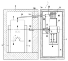
図1は、本発明によるヘリウム再液化装置を含む計測システムの一例である生体磁気計測システムを示す部分断面図である。生体磁気計測システム1は、脳の活動等を高時空間分解能で非侵襲的に計測可能な超電導量子干渉計(以下、「SQUID」という)2を備えており、人間の脳等から発せられる磁界を検出可能なものである。このSQUID2は、その内部におよそ4Kの液体ヘリウムを貯留するデュワー(貯留槽)3に内包されており、デュワー3内の液体ヘリウムによって動作温度であるおよそ4Kに冷却される。
FIG. 1 is a partial cross-sectional view showing a biomagnetic measurement system which is an example of a measurement system including a helium reliquefaction apparatus according to the present invention. The biomagnetic measurement system 1 includes a superconducting quantum interferometer (hereinafter referred to as “SQUID”) 2 capable of noninvasively measuring brain activity and the like with high spatio-temporal resolution, and a magnetic field generated from a human brain or the like. Can be detected. The SQUID 2 is contained in a dewar (storage tank) 3 that stores approximately 4K of liquid helium therein, and is cooled to approximately 4K, which is an operating temperature, by the liquid helium in the
SQUID2およびデュワー3は、非磁性体の隔壁4により画成された磁気シールド室SR内に配置されている。図1からわかるように、デュワー3は、支持部材5によって、水平に延びる軸6の周りに回動自在に支持されており、デュワー3の下方には、図示されない座部および図示されないベッドが配置される。これにより、生体磁気計測システム1では、デュワー3を軸6の周りに回動(傾斜)させることにより、座部に着座した被検者またはベッドに横たわった被検者の脳等から発せられる磁界を計測することができる。
The SQUID 2 and the
生体磁気計測システム1は、希少な資源であると共に比較的高価なヘリウムを有効に活用すべく、SQUID2の冷却によりデュワー(液体ヘリウム貯留槽)3内で気化したヘリウムを回収し、再液化させてデュワー3に返送するヘリウム再液化装置20を有している。ヘリウム再液化装置20は、後述のGM冷凍機等を収容するコールドチャンバ23や各種配管類を収容する容器26を有し、磁気シールド室SRの隣に配置された収容室AR内に配置されている。収容室ARを画成する隔壁7の内面には、ヘリウム再液化装置20から発せられる音や磁気の外部への漏洩を抑制するために、磁気シールド材が貼着されている。
The biomagnetic measurement system 1 collects the helium vaporized in the dewar (liquid helium storage tank) 3 by cooling the SQUID 2 and re-liquefies it in order to effectively use helium, which is a scarce resource and is relatively expensive. It has a
コールドチャンバ23および容器26の支持機構には、磁気シールド室SR内の軸6と同軸かつ水平に延びるシャフト8が固定されており、シャフト8は、支持ブロック9によって回転自在に支持されている。シャフト8には、ウォームギア機構等の減速機構10を介して回転ハンドル11が接続されており、回転ハンドル11を操作することにより、コールドチャンバ23や容器26をシャフト8の周りに回動させることができる。なお、容器26の下部には、カウンタウェイトWが取り付けられている。
A
また、生体磁気計測システム1は、磁気シールド室SRを画成する隔壁4と、当該隔壁4と対向する収容室ARの隔壁7とを貫通する駆動シャフト12を有している。収容室AR内のシャフト8と結合させた駆動シャフト12を回転させれば、磁気シールド室SR内から収容室AR内のコールドチャンバ23や容器26を回動(傾斜)させることができる。すなわち、生体磁気計測システム1では、患者の姿勢に合わせて磁気シールド室SR内のデュワー3を移動させた際に、収容室AR内のヘリウム再液化装置20をデュワー3の姿勢に合わせて移動させることができる。
In addition, the biomagnetic measurement system 1 includes a
図1に示されるように、デュワー3とヘリウム再液化装置20のコールドチャンバ23とは、多層構造を有するトランスファチューブ14を介して互いに接続される。トランスファチューブ14は、後述の高温回収管L1、第2冷却管L5、低温回収管L6および返送管L7を一体化させたものである。トランスファチューブ14は、磁気シールド室SRの隔壁4に形成された弧状の長穴4aと、収容室ARの隔壁7に形成された弧状の長穴7aとを貫通する。長穴4aおよび7aは、デュワー3やヘリウム再液化装置20の回動中心(軸6やシャフト8等)を中心として形成されている。長穴4aおよび7aには、デュワー3、ヘリウム再液化装置20およびトランスファチューブ14の移動が完了した段階で、磁気シールド材15が装填される。
As shown in FIG. 1, the
図2は、ヘリウム再液化装置20の系統図である。同図に示されるように、ヘリウム再液化装置20は、主として、循環ポンプ21、2台のGM冷凍機22、2台の精製器30、凝縮器40、GM冷凍機22、精製器30および凝縮器40を収容するコールドチャンバ23、デュワー3から比較的高温(およそ300K)のヘリウムガスを回収するための高温回収管L1を含む。各GM冷凍機22は、ヘリウムガスをおよそ40Kまで冷却するための第1冷凍部22aおよびヘリウムガスをおよそ4Kまで冷却するための第2冷凍部22bを有する。
FIG. 2 is a system diagram of the
高温回収管L1は、デュワー3の上部と循環ポンプ21の吸入口とに接続されており、中途にバルブV1、マスフローメータMF3および電磁弁EV1(ノーマルオープン)を有する。循環ポンプ21の吐出口には、ガス管L2の一端が接続されており、ガス管L2は、フィルタF1,F2およびF3、一定流量制御弁MFC1、流量計FMおよびバルブV2を中途に有する。ガス管L2の他端は、コールドチャンバ23内の一方の精製器30の流体入口に接続されている。この精製器30の流体出口には、逆止弁50を介して第1冷却管L3の一端が接続されている。第1冷却管L3は、一方のGM冷凍機22の第1冷凍部22aに配置される伝熱管HP1と、当該一方のGM冷凍機22の第2冷凍部22bに配置される伝熱管HP2とを有する。そして、第1冷却管L3の他端は、凝縮器40に接続されている。
The high temperature recovery pipe L1 is connected to the upper part of the
また、ガス管L2からは、フィルタF3と一定流量制御弁MFC1との間で、ガス管L4が分岐されている。ガス管L4は、一定流量制御弁MFC2、流量計FMおよびバルブV3を中途に有する。ガス管L4の他端は、コールドチャンバ23内の他方の精製器30の流体入口に接続されている。この精製器30の流体出口には、逆止弁50を介して第2冷却管L5の一端が接続されている。第2冷却管L5は、一方のGM冷凍機22の第2冷凍部22bに配置される伝熱管HP3を有する。そして、第2冷却管L5の他端は、デュワー3の上部に接続されている。なお、第2冷却管L5は、上述のトランスファチューブ14の最外層に設けられ、その中央を流通するヘリウムを保冷する役割を果たす。
Further, the gas pipe L4 is branched from the gas pipe L2 between the filter F3 and the constant flow control valve MFC1. The gas pipe L4 has a constant flow control valve MFC2, a flow meter FM, and a valve V3 in the middle. The other end of the gas pipe L4 is connected to the fluid inlet of the
デュワー3から蒸発した比較的高温(およそ300K)のヘリウムガスは、循環ポンプ21によってデュワー3から回収される。回収されたヘリウムガスの一部は、ガス管L2を介して一方の精製器30に送られ、この精製器30によりヘリウムガス中の窒素や酸素といった不純物が除去される。この精製器30から流出したヘリウムガスは、第1冷却管L3を流通する間に、一方のGM冷凍機22の第1冷凍部22aと、当該冷凍機22の第2冷凍部22bとで段階的に冷却された後、凝縮器40へと送られる。
The relatively high temperature (about 300 K) helium gas evaporated from the
凝縮器40は、2台のGM冷凍機22の第2冷凍部22bに接続されており、凝縮器40の器内温度は、各第2冷凍部22bによりおよそ4Kに保たれている。凝縮器40には、低温回収管L6と返送管L7とが接続されている。デュワー3で発生した低温(およそ4〜10K)のヘリウムガスは、低温回収管L6を介して凝縮器40に送られ、凝縮器40で極低温(およそ4K)の液体ヘリウムへと再液化させられる。同様に、第1冷却管L3からのヘリウムガスも、凝縮器40で極低温の液体ヘリウムへと再液化させられる。再液化されたヘリウムは、凝縮器40から返送管L7を介してデュワー3へと戻される。また、デュワー3から回収された比較的高温(およそ300K)のヘリウムガスの残りは、ガス管L4を介して他方の精製器30に送られ、この精製器30によりヘリウムガス中の窒素や酸素といった不純物が除去される。この精製器30から流出したヘリウムガスは、第2冷却管L5を流通する間に、一方のGM冷凍機22の第1冷凍部22aでおよそ40Kに冷却された後、デュワー3へと送られる。
The
一方、ガス管L2の循環ポンプ21とフィルタF1との間には、バルブV4、フィルタF4、マスフローメータMF4および電磁弁EV4を介してヘリウムボンベ24が接続されている。ヘリウムボンベ24は、常温(300K)のヘリウムガスを貯留するものである。これにより、ヘリウム再液化装置20では、電磁弁EV4とバルブV2とを開放させることにより、ヘリウムボンベ24からのヘリウムガスを第1冷却管L3に送り込み、凝縮器40で極低温の液体ヘリウムへと再液化させた上でデュワー3に供給(補充)することが可能となる。
On the other hand, a
更に、図2に示されるように、マスフローメータMF5が、電磁弁EV2(ノーマルクローズ)を介してガス管L2の流量計FMとバルブV2との間に、電磁弁EV3(ノーマルクローズ)を介してガス管L4の流量計FMとバルブV3との間に接続されている。そして、このマスフローメータMF5には、バルブV5および真空引きポートを介して排気ポンプ(吸引手段)25が接続されている。排気ポンプ25は、後述のように精製器30から不純物を除去する際に使用される。
Further, as shown in FIG. 2, the mass flow meter MF5 is connected between the flow meter FM of the gas pipe L2 and the valve V2 via the electromagnetic valve EV3 (normally closed) via the electromagnetic valve EV2 (normally closed). The gas pipe L4 is connected between the flow meter FM and the valve V3. An exhaust pump (suction means) 25 is connected to the mass flow meter MF5 via a valve V5 and a vacuum port. The
加えて、ヘリウム再液化装置20は、圧力センサP1,P2およびP3を有する。圧力センサP1は、デュワー3内のヘリウムガスの圧力を検出する。圧力センサP2は、第1冷却管L3に接続された精製器30の入口におけるヘリウムガスの圧力を検出し、圧力センサP3は、第2冷却管L5に接続された精製器30の入口におけるヘリウムガスの圧力を検出する。これらの圧力センサP1〜P3は、図示されない他のセンサと共にコントローラ(図示省略)に接続されている。このコントローラは、各種センサの検出値に基づいて、上述の循環ポンプ21、排気ポンプ25および各種バルブ等を制御する。
In addition, the
次に、上述のヘリウム再液化装置20の精製器30、逆止弁50および凝縮器40について、それぞれ詳細に説明する。
Next, the
(精製器)
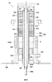
精製器30は、デュワー3から回収されたヘリウムガス中の不純物を冷却・固化させて捕捉するものであり、図3に示されるように、良好な熱伝導性を有する銅材等により概ね円筒状に形成された精製器本体301を有する。精製器30は、上述のコールドチャンバ23内に配置され、精製器30の周囲は真空雰囲気に保たれる。精製器本体301は、上部302と、上部302よりも大きい厚みを有する下部303とを含む。下部303には、環状の孔部303aが形成されており、孔部303aには、加熱ヒータHが配置される。精製器本体301(下部303)の下端部は、連結部材304を介してGM冷凍機22の第1冷凍部22aに連結されている。これにより、ヘリウム再液化装置20の稼動中、精製器本体301は、GM冷凍機22によっておよそ40Kに冷却される。精製器本体301(上部302)の上端部は、閉鎖部材305によって閉鎖されている。
(Purifier)
The
精製器本体301の中心には、円筒状の導入管306が配置されており、導入管306の周囲には、円筒状の内管307が導入管306と同軸に配置されている。内管307は、下部303の内壁面から内方に延びる支持部303bに固定されている。導入管306の上端は、固定部材308により、内管307の上端に固定されている。上述の閉鎖部材305と導入管306の上端との間には、空間が画成される。また、導入管306の外壁面、内管307の内壁面および固定部材308により、断熱空間309が画成される。この断熱空間309の内部は、精製器本体301の周囲と同様に真空雰囲気に保たれる。
A
精製器本体301の上部302の内壁面と、内管307の外壁面との間には、複数の流路形成部材310が精製器本体301の軸方向に配設されている。流路形成部材310は、良好な熱伝導性を有する銅材により形成されており、内管307が挿入される中心孔部と概ね扇形の開口部311とを有する天井部312と、天井部312の外周から下方に延びる筒状の側壁314とを有する(図3および図4参照)。そして上下に隣り合う流路形成部材310同士は、開口部311同士が上下に重なり合わないように配置され、上下に隣り合う流路形成部材310(天井部312)同士の間には、冷却室315が画成される。また、上下に隣り合う流路形成部材310(天井部312)同士の間には、仕切板319が配置されている。仕切板319は、上側の位置する開口部311の一方の側縁部(例えば図4における下側の側縁部)と、下側に位置する開口部311の他方の側縁部(例えば図5における上側の側縁部)とに固定され、冷却室315内の流体の基本的な流れ方向を一方向にする。
Between the inner wall surface of the
これにより、上下に隣り合う冷却室315同士は、ヘリウムガスが上側の冷却室315の内壁に沿って流通してから下側の冷却室315に流れ込むように連通され、この結果、ヘリウムガスが流通する蛇行流路が形成される。そして、各冷却室315の内部には、ヘリウムガスの進路を変えて冷却室315内にジグザグ流路を形成するように複数の邪魔板320が配置されている。更に、本実施形態において、流路形成部材310は、精製器本体301内の下側(下流側)に配置されるものほど低背とされる。従って、冷却室315の高さ(精製器本体310の軸方向における冷却室315の寸法)は、精製器本体301内の下端(出口324)に近づくにつれて小さくなる。
As a result, the cooling
精製器本体301の下部303の内壁面と、内管307の外壁面との間には、下部303の上端付近に位置するように多孔板(銅製金網)321が配置されている。この多孔板321の下方には、所定間隔を隔てて多孔板(銅製金網)322が配置されている。多孔板322と下部303の支持部303bとの間には、空間323が画成され、空間323には、出口管(流体出口)324が接続されている。
Between the inner wall surface of the
そして、多孔板321と多孔板322との間の空間には、多数の微小球体(微小粒体)が高密度に充填されている。これにより、精製器本体301の出口側(最下流側)に、流体の流通を許容すると共に当該流体と十分に接触可能な多孔性捕捉部325が形成される。本実施形態では、多孔性捕捉部325の上側のおよそ3分の1の領域に、直径2mmの銅球が充填されており、多孔性捕捉部325の中央のおよそ3分の1の領域に、直径1mmの銅球が充填されており、多孔性捕捉部325の下側のおよそ3分の1の領域に、直径0.5mmの銅球が充填されている。すなわち、本実施形態では、微小球体のサイズが流体の流れ方向に沿って段階的に変化させられている。なお、多孔性捕捉部325には、微小球体(微小粒体)の代わりに、折り畳まれたメッシュ材が配置されてもよい。
The space between the
上述の精製器30では、導入管306の入口(流体入口)306aにデュワー3から回収されたおよそ300Kのヘリウムガスが導入される。ヘリウムガスは、導入管306の内部を上昇し、導入管306の上端から流出する。導入管306の上端から流出したヘリウムガスは、複数の流路形成部材310によって導入管306の周囲に画成されている蛇行流路(各冷却室315)に流入する。
In the
最上段の冷却室315に流れ込んだヘリウムガスは、当該冷却室315の内壁(側壁314の内周面)に沿って流通し、開口部311を介して下方の冷却室315へと流れ込む。そして、ヘリウムガスは、順次下方の冷却室315へと流下していく。この際、各流路形成部材310は、精製器本体301を介してGM冷凍機22によっておよそ40Kに冷却されているので、ヘリウムガスは、流路形成部材310の天井部312、側壁314、仕切板319、邪魔板320と接触し、均一に冷却される。
The helium gas that has flowed into the
このように、精製器30では、精製器本体301の内部に上述の複数の冷却室315が上述のように配設されているので、精製器本体301におけるヘリウムガスの流路をより一層長くし、各冷却室315の壁面等とヘリウムガスとが接触する確立を高めることができる。また、冷却室315の高さを精製器本体301の出口に近づくにつれて小さくすることにより、ヘリウムガスを均一に冷却して、精製器30の閉塞を良好に抑制することが可能となる。
As described above, in the
最下段の冷却室315を流出したヘリウムガスは、多孔板321を介して多孔性捕捉部325に流入する。上述のように、多孔性捕捉部325は、高密度に集合させられた多数の銅製の微小球体を含み、これらの微小球体は、精製器本体301を介してGM冷凍機22によっておよそ40Kに冷却されている。従って、ヘリウムガスが多孔性捕捉部325の多数の微小球体同士の間に形成された微小な隙間を通過する際に、ヘリウムガス中の不純物は、微小球体を介して冷却されて固化し、微小な隙間に確実に捕捉されることになる。この結果、精製器30によれば、デュワー3から回収されるヘリウムガス中の窒素や酸素といった不純物を冷却・固化させて確実に捕捉することが可能となる。
The helium gas that has flowed out of the
また、本実施形態のように、微小球体のサイズをヘリウムガスの流れ方向に沿って段階的に減少させることにより、ヘリウムガス中の不純物を確実に捕捉して、不純物が精製器30から排出されてしまうことを確実に抑制することができる。更に、精製器本体301は、その入口306aから多孔性捕捉部325の入口(多孔板322)までの間に蛇行流路を含むので、入口306aから多孔性捕捉部325までの距離をできるだけ長くすることができる。これにより、多孔性捕捉部325の前段において、不純物をできるだけ捕捉すると共にヘリウムガスの温度を低下させておくことが可能となる。
Further, as in this embodiment, by reducing the size of the microsphere stepwise along the flow direction of the helium gas, the impurities in the helium gas are reliably captured and the impurities are discharged from the
(逆止弁)
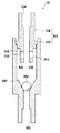
上述の精製器30の出口管324に接続される逆止弁50は、従来の逆止弁が動作し得なかった例えばおよそ4〜40Kの極低温環境下で使用され得るものである。図6に示されるように、逆止弁50は、弁本体501と、弁本体501の内部に移動自在に収容された弁体502とを有する。弁本体501は、下側半部503および上側半部504を含む。下側半部503および上側半部504は、何れも高い熱伝導性を有する銅材により概ね筒状に形成されている。また、本実施形態において、弁体502は、セラミック等の軽量かつ剛性の高い素材により球状に形成されている。
(Check valve)
The
下側半部503は、下端側に弁体502の直径よりも小さな内径を有する弁入口505を含むと共に、上端側に弁入口505(弁体502の直径)よりも大きな内径を有する腔部506を含む。そして、下側半部503の内部には、弁入口505と腔部506との間に、テーパ面507が形成されている。テーパ面507は、下から上に向かって拡げられており、このテーパ面507によって弁体502が受けられる。上側半部504は、上端側に弁出口508を含むと共に、下端側に弁体502の弁出口508への移動を規制する突起509を含む。突起509には、下側半部503の腔部506(弁入口505)と、上側半部504の弁出口508とを連通させる開口部510が形成されている。
The
この逆止弁50は、好ましくは、弁入口505が下に、弁出口508が上に位置する状態で使用される。精製器30から弁入口505にヘリウムガスが流れ込むと、軽量の弁体502は、ヘリウムガスによって弁出口508に向けて移動させられ、それにより、弁入口505が開放されることになる。そして、弁入口505から腔部506に流れ込んだヘリウムガスは、突起509の開口部510を介して弁出口508へと流れていく。また、弁体502の弁出口508への移動は、突起509の先端により規制される。一方、弁入口505に対するヘリウムガスの供給を停止させたり、弁入口505の圧力を弁出口508の圧力よりも小さく設定したりすると、弁体502は、弁入口505に向かって移動する。そして、弁体502は、テーパ面507と係合し、弁入口505を閉鎖することになる。
This
このように、弁体502は、弁入口505と弁出口508との間の圧力差に応じて弁入口505を開放または閉鎖するように移動する。従って、逆止弁50では、弁入口505と弁出口508との間に圧力差を生じさせるだけで、弁入口505を開放または閉鎖することができる。このような単純な構造を有しているため、逆止弁50は、4〜40Kの低温環境下においても極めて確実に作動する。なお、弁体502は、球状に形成される代わりに、テーパ面507に係合する錐体として形成されてもよい。
Thus, the
(精製器からの不純物の除去処理)
上述のヘリウム再液化装置20が稼動されていくと、上述の精製器30の多孔性捕捉部325等が固化した窒素や酸素といった不純物によって閉塞してしまうおそれがある。精製器30の多孔性捕捉部325等が閉塞してしまうおそれがある。そして、精製器30が閉塞を起こし始めた際には、圧力センサP2,P3によって検出される精製器30の入口におけるヘリウムガスの圧力が所定の閾値を上回る。このため、ヘリウム再液化装置20のコントローラは、例えば圧力センサP2の検出値が上記閾値を上回った際には、電磁弁EV2およびバルブV5を開放させると共に、排気ポンプ25を作動させる。また、コントローラは、適切なタイミングで冷凍機22を停止させ、第1冷却管L3に接続された精製器30の加熱ヒータHを作動させる。
(Removal of impurities from the purifier)
As the above-described
精製器30の加熱ヒータHが作動されると、当該精製器30の多孔性捕捉部325や、蛇行流路内に捕捉されている不純物が加熱されて気化する。また、排気ポンプ25が作動されると、逆止弁50の弁入口505が弁出口508よりも低圧になるので、弁体502は弁入口505を閉鎖するように移動する。これにより、精製器30内で気化した不純物が逆止弁50の下流側に流出するのを阻止することができる。そして、精製器30内で気化した不純物は、排気ポンプ25によって吸引されて外部に排出される。この結果、ヘリウム再液化装置20では、不純物の下流側への流出を確実に抑制しながら、精製器30から確実に不純物を除去することが可能となる。
When the heater H of the
なお、第2冷却管L5に接続された精製器30から不純物を除去する際には、電磁弁EV3およびバルブV5を開放させると共に、排気ポンプ25を作動させ、更に、当該精製器30の加熱ヒータHを作動させればよい。また、高温回収管L1には、図2に示されるように、中途に電磁弁EV5を有するヘリウム排出管が接続されており、上述の精製器30からの不純物の除去処理に際しては、電磁弁EV5が開放され、デュワー3内で気化したヘリウムガスは、ヘリウム排出管を介して大気中に排出される。
When removing impurities from the
(凝縮器)
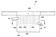
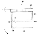
凝縮器40は、図7に示されるように、チャンバ402を有する凝縮器本体401と、多数の孔404を有する多孔性ブロック403(図7および図8参照)と、取付板405とを有する。凝縮器本体401、多孔性ブロック403および取付板405は、何れも、高い熱伝導性を有する銅材により形成されている。多孔性ブロック403の孔404は、それぞれ下方にのみ開口しており、多孔性ブロック403の上部は、取付板405の裏面中央部に固定される。同様に、凝縮器本体401の上端(開放端)も取付板405の裏面中央部に固定され、多孔性ブロック403はチャンバ402内に収容される。この際、多孔性ブロック403の下端面とチャンバ402の底面との間には空間が画成される。更に、凝縮器本体401の下部(チャンバ402の下方)には、チャンバ402に連なる液溜め部406が形成されている。
(Condenser)
As shown in FIG. 7, the
取付板405の両端部は、それぞれGM冷凍機22の第2冷凍部22bに接続され、これにより、ヘリウム再液化装置20の稼動中、凝縮器本体401、多孔性ブロック403および取付板405は、GM冷凍機22によっておよそ4Kに冷却される。また、凝縮器本体401には、デュワー3から低温(およそ4〜10K)のヘリウムガスを回収するための低温回収管L6がチャンバ402の上部と連通するように接続される。更に、凝縮器本体401には、第1冷却管L3がチャンバ402の下部と連通するように接続される。そして、凝縮器本体401には、再液化されたヘリウムをデュワー3へと返送するための返送管L7が接続される。
Both ends of the mounting
上述の凝縮器40では、凝縮器本体401のチャンバ402内に第1冷却管L3および低温回収管L6を介して低温(およそ4〜10K)のヘリウムガスが導入される。かかるヘリウムガスは、チャンバ402内において、多孔性ブロック403の孔404内に流入し、多孔性ブロック403等と熱交換することにより、再液化し、孔404からチャンバ402の底部へと滴下する。そして、再液化されたヘリウムは、返送管L7を介して適量ずつデュワー3に返送され、余剰のヘリウムは、液溜め部406内に貯留される。この際、ヘリウムガス中になお窒素や酸素といった不純物が残留していたとしても、不純物は、チャンバ402内でヘリウムと同様に冷却されて固化し、重力により液溜め部406の底に溜まっていくことになる。これにより、凝縮器40によれば、精製器30にて完全に処理しきれなかった窒素や酸素といった不純物を確実に捕捉可能となる。
In the
ところで、上述のように、患者の姿勢に合わせて磁気シールド室SR内のデュワー3が移動させられた際、収容室AR内のコールドチャンバ23や容器26もデュワー3の姿勢に合うように移動(傾斜)させられる。本実施形態では、ヘリウム再液化装置20が移動(傾斜)させられると、容器26内の凝縮器40は、図9の矢印方向に傾いていく。
By the way, as described above, when the
このため、本実施形態において、凝縮器40(取付板405)は、図9からわかるように、同図における矢印方向に微小角度θ(例えば2〜3°程度)だけ傾けた状態で2台のGM冷凍機22に連結されている。また、固化した不純物を液体ヘリウムと共に貯留する液溜め部406は、凝縮器40(容器26)の回動中心(シャフト8等)から最も遠くなるように凝縮器本体401に設けられている。そして、凝縮器本体401と返送管L7との接続部は、液溜め部406に形成される液面LLのうち、凝縮器本体401を傾斜させても変位しない位置(図8の液面LLの中心)の延長線上に配置される。これにより、凝縮器本体401が傾斜させられたとしても、デュワー3へと返送される液化ヘリウムに不純物が混入するのを確実に抑制することが可能となる。
For this reason, in this embodiment, as can be seen from FIG. 9, two condensers 40 (mounting plates 405) are tilted by a minute angle θ (for example, about 2 to 3 °) in the direction of the arrow in FIG. It is connected to the
なお、本発明は、その思想や主要な特徴から逸脱することなく、他のいかなる形態においても実施され得る。そのため、上述の実施形態は、あらゆる点で単なる例示にすぎず、限定的に解釈されてはならない。 It should be noted that the present invention can be implemented in any other form without departing from the concept and main features thereof. For this reason, the above-described embodiment is merely an example in all respects and should not be construed in a limited manner.
1 生体磁気計測システム
20 ヘリウム再液化装置
22 GM冷凍機
30 精製器
325 多孔性捕捉部
40 凝縮器
50 逆止弁
DESCRIPTION OF SYMBOLS 1
Claims (9)
精製器本体と、
前記ヘリウムガスの流通を許容すると共に当該ヘリウムガスと十分に接触するように構成されており、前記精製器本体の出口側に配置されると共に冷熱源に接続された多孔質性の捕捉手段とを備えることを特徴とする精製器。 Helium vaporized in a storage tank storing cryogenic liquid helium is recovered, re-liquefied and used for helium re-liquefaction treatment to return to the storage tank, and the impurities in the helium gas recovered from the storage tank are cooled. A purifier that solidifies and captures,
A purifier body,
A porous trapping means configured to allow the flow of the helium gas and to be in sufficient contact with the helium gas, disposed on the outlet side of the purifier body, and connected to a cold heat source; A purifier characterized by comprising.
冷熱源に接続された精製器本体と、
前記精製器本体の内部に並設された複数の冷却室とを備え、
互いに隣り合う前記冷却室同士は、ヘリウムガスが一方の冷却室の内壁に沿って流通してから他方の冷却室に流れ込むように連通されており、前記精製器本体の軸方向における前記冷却室の寸法は、前記精製器本体の出口に近づくにつれて小さくなっていることを特徴とする精製器。 Helium vaporized in a storage tank storing cryogenic liquid helium is recovered, re-liquefied and used for helium re-liquefaction treatment to return to the storage tank, and the impurities in the helium gas recovered from the storage tank are cooled. A purifier that solidifies and captures,
A purifier body connected to a cold heat source;
A plurality of cooling chambers arranged in parallel inside the purifier body,
The cooling chambers adjacent to each other are communicated so that helium gas flows along the inner wall of one cooling chamber and then flows into the other cooling chamber, and the cooling chambers in the axial direction of the purifier main body are connected to each other. The size of the purifier decreases as it approaches the outlet of the purifier body.
前記貯留槽から回収されたヘリウムガス中の不純物を冷却・固化させて捕捉する精製器と、
前記精製器により捕捉された不純物を加熱するためのヒータと、
前記精製器の流体入口に接続された吸引手段と、
前記精製器の流体出口に接続されており、弁入口および弁出口を有する本体と、前記本体の内部に配置されており、前記弁入口と前記弁出口との間の圧力差に応じて前記弁入口を開放または閉鎖するように移動することができる弁体とを含む逆止弁とを備えるヘリウム再液化装置。 A helium reliquefaction device that recovers helium vaporized in a storage tank storing cryogenic liquid helium, reliquefies it, and returns it to the storage tank,
A purifier that cools and solidifies impurities in the helium gas recovered from the storage tank;
A heater for heating impurities trapped by the purifier;
Suction means connected to the fluid inlet of the purifier;
A body connected to the fluid outlet of the purifier and having a valve inlet and a valve outlet; and disposed within the body, the valve depending on a pressure difference between the valve inlet and the valve outlet A helium reliquefaction device comprising a check valve including a valve body capable of moving to open or close the inlet.
弁入口および弁出口を有する本体と、
前記本体の内部に配置されており、前記弁入口と前記弁出口との間の圧力差に応じて前記弁入口を開放または閉鎖するように移動することができる弁体とを含む弁機構。 A valve mechanism used in a low temperature environment,
A body having a valve inlet and a valve outlet;
A valve mechanism that is disposed inside the main body and includes a valve body that can move to open or close the valve inlet according to a pressure difference between the valve inlet and the valve outlet.
凝縮器本体と、
前記凝縮器本体に設けられており、前記凝縮器本体内で固化した不純物を液化ヘリウムと共に貯留する液溜め部とを備えることを特徴とする凝縮器。 The helium vaporized in a storage tank storing cryogenic liquid helium is collected, re-liquefied, and used for helium re-liquefaction processing to be returned to the storage tank. A vessel,
The condenser body,
A condenser provided in the condenser body, and comprising a liquid reservoir for storing impurities solidified in the condenser body together with liquefied helium.
前記凝縮器本体と前記返送管との接続部は、前記液溜め部に形成される液面のうち、前記傾斜手段によって前記凝縮器本体を傾斜させても変位しない位置に関連付けて配置されていることを特徴とする請求項8に記載の凝縮器。
A return pipe for returning liquid helium from the condenser body to the storage tank; and a tilting means for tilting the condenser body;
The connecting portion between the condenser main body and the return pipe is disposed in association with a position where the condenser main body is not displaced even when the condenser main body is tilted by the tilting means on the liquid surface formed in the liquid reservoir. The condenser according to claim 8.
Priority Applications (2)
| Application Number | Priority Date | Filing Date | Title |
|---|---|---|---|
| JP2004107890A JP2005291628A (en) | 2004-03-31 | 2004-03-31 | Helium re-liquefying device, purifier, valve mechanism, and condenser |
| PCT/JP2005/006190 WO2005095877A1 (en) | 2004-03-31 | 2005-03-30 | Apparatus for re-liquefying helium, purifying device, valve mechanism and condenser |
Applications Claiming Priority (1)
| Application Number | Priority Date | Filing Date | Title |
|---|---|---|---|
| JP2004107890A JP2005291628A (en) | 2004-03-31 | 2004-03-31 | Helium re-liquefying device, purifier, valve mechanism, and condenser |
Publications (1)
| Publication Number | Publication Date |
|---|---|
| JP2005291628A true JP2005291628A (en) | 2005-10-20 |
Family
ID=35063871
Family Applications (1)
| Application Number | Title | Priority Date | Filing Date |
|---|---|---|---|
| JP2004107890A Pending JP2005291628A (en) | 2004-03-31 | 2004-03-31 | Helium re-liquefying device, purifier, valve mechanism, and condenser |
Country Status (2)
| Country | Link |
|---|---|
| JP (1) | JP2005291628A (en) |
| WO (1) | WO2005095877A1 (en) |
Cited By (2)
| Publication number | Priority date | Publication date | Assignee | Title |
|---|---|---|---|---|
| JP2008001539A (en) * | 2006-06-21 | 2008-01-10 | Univ Of Tokyo | Helium purifier |
| CN107621121A (en) * | 2017-09-22 | 2018-01-23 | 清华大学 | Combined type helium purification devices |
Families Citing this family (2)
| Publication number | Priority date | Publication date | Assignee | Title |
|---|---|---|---|---|
| GB2479003B (en) * | 2010-03-26 | 2016-09-07 | Iceoxford Ltd | Cryogenic apparatus |
| US20240401876A1 (en) * | 2021-09-24 | 2024-12-05 | L'air Liquide, Societe Anonyme Pour L'etude Et L’Exploitation Des Procedes Georges Claude | Process and apparatus for the recovery of boil-off gas from the liquefaction of hydrogen |
Family Cites Families (4)
| Publication number | Priority date | Publication date | Assignee | Title |
|---|---|---|---|---|
| JPS5886966U (en) * | 1981-12-08 | 1983-06-13 | 松下冷機株式会社 | fluid control valve |
| JPH09152051A (en) * | 1995-11-30 | 1997-06-10 | Sanyo Electric Co Ltd | Check valve |
| JP3183498B2 (en) * | 1997-03-07 | 2001-07-09 | 住友重機械工業株式会社 | Helium reliquefaction equipment |
| JP3645526B2 (en) * | 2002-01-25 | 2005-05-11 | 独立行政法人科学技術振興機構 | High performance helium gas purifier |
-
2004
- 2004-03-31 JP JP2004107890A patent/JP2005291628A/en active Pending
-
2005
- 2005-03-30 WO PCT/JP2005/006190 patent/WO2005095877A1/en not_active Ceased
Cited By (2)
| Publication number | Priority date | Publication date | Assignee | Title |
|---|---|---|---|---|
| JP2008001539A (en) * | 2006-06-21 | 2008-01-10 | Univ Of Tokyo | Helium purifier |
| CN107621121A (en) * | 2017-09-22 | 2018-01-23 | 清华大学 | Combined type helium purification devices |
Also Published As
| Publication number | Publication date |
|---|---|
| WO2005095877A1 (en) | 2005-10-13 |
Similar Documents
| Publication | Publication Date | Title |
|---|---|---|
| CN104471328B (en) | Reduce clogging in cryocooler systems such as those used in magnetic resonance imaging systems | |
| TWI411462B (en) | Fluid purification system with low temperature purifier | |
| JP7128544B2 (en) | heat exchangers, refrigerators and sintered bodies | |
| JP5931049B2 (en) | Cold water tank | |
| JP5043199B2 (en) | Method and system for freezing biological material at a controlled rate | |
| JP5229674B2 (en) | Gas fuel storage container and use thereof | |
| CN105983293B (en) | For purification gas device and method and regenerate the method for the gas | |
| JP2005291628A (en) | Helium re-liquefying device, purifier, valve mechanism, and condenser | |
| WO2015041726A1 (en) | Systems and methods for cryogenic refrigeration | |
| JP4565226B2 (en) | Refrigerant circulation device and refrigerant circulation method | |
| TW201102152A (en) | Continuous fine ash depressurization system | |
| JP3645526B2 (en) | High performance helium gas purifier | |
| US12163626B2 (en) | Cryostat for operation with liquid helium and method of operating the same | |
| JP2007218317A (en) | Low temperature liquid / gas hydrogen storage tank | |
| JPH04306472A (en) | Cryostat equipped with liquefying refrigerating machine | |
| JP3645551B2 (en) | Helium gas purifier with automatic shut-off valve | |
| TW200905076A (en) | Cryopump | |
| JP2011156536A (en) | Cleaning system and cleaning method | |
| JP2005012043A (en) | High thermal efficiency dewar | |
| JP6207430B2 (en) | Oil separator | |
| JP3708527B2 (en) | Control device and control method for circulating liquid helium reliquefaction device | |
| RU2215901C2 (en) | Adsorption pump | |
| JP2011131216A (en) | Cleaning system and washing method | |
| CN101238323A (en) | hydrogen storage device | |
| JPS59152202A (en) | Storage method of hydrogen |