JP2005291604A - Bathroom heating and drying machine - Google Patents
Bathroom heating and drying machine Download PDFInfo
- Publication number
- JP2005291604A JP2005291604A JP2004106005A JP2004106005A JP2005291604A JP 2005291604 A JP2005291604 A JP 2005291604A JP 2004106005 A JP2004106005 A JP 2004106005A JP 2004106005 A JP2004106005 A JP 2004106005A JP 2005291604 A JP2005291604 A JP 2005291604A
- Authority
- JP
- Japan
- Prior art keywords
- air
- bathroom
- heating
- damper
- heater
- Prior art date
- Legal status (The legal status is an assumption and is not a legal conclusion. Google has not performed a legal analysis and makes no representation as to the accuracy of the status listed.)
- Pending
Links
- 238000010438 heat treatment Methods 0.000 title claims abstract description 96
- 238000001035 drying Methods 0.000 title claims abstract description 17
- 238000009423 ventilation Methods 0.000 claims abstract description 24
- 238000007664 blowing Methods 0.000 claims abstract description 6
- 238000010981 drying operation Methods 0.000 claims description 12
- 238000003287 bathing Methods 0.000 description 1
- 230000008878 coupling Effects 0.000 description 1
- 238000010168 coupling process Methods 0.000 description 1
- 238000005859 coupling reaction Methods 0.000 description 1
- 230000007423 decrease Effects 0.000 description 1
- 239000000463 material Substances 0.000 description 1
- XLYOFNOQVPJJNP-UHFFFAOYSA-N water Substances O XLYOFNOQVPJJNP-UHFFFAOYSA-N 0.000 description 1
Images
Landscapes
- Central Heating Systems (AREA)
- Ventilation (AREA)
Abstract
Description
本発明は、戸建て住宅あるいは集合住宅などに設けられた浴室内の空気を換気したり、暖房したりする機能を備えた浴室暖房乾燥機に関する。 The present invention relates to a bathroom heater / dryer having a function of ventilating or heating air in a bathroom provided in a detached house or an apartment house.
近年の戸建て住宅や集合住宅などにおいては、浴室内の換気、暖房を行うために浴室暖房乾燥機を設置することが多くなっているが、従来の浴室暖房乾燥機として、例えば、特許文献1に記載のものがある。図7に示すように、従来の浴室暖房乾燥機70においては、吸気口71、吹出口72および排気口73を有する本体77内に送風ファン74が設けられ、吹出口72にヒータ74が配置され、本体77内にダンパ76が支軸76aを中心に揺動可能に設けられている。
In recent detached houses and apartment houses, bathroom heating dryers are often installed to ventilate and heat the bathroom. For example, Patent Literature 1 discloses a conventional bathroom heating dryer. There is a description. As shown in FIG. 7, in a conventional bathroom heater /
ダンパ76は、送風ファン74によって浴室内の吸気口71から吸い込まれた空気を吹出口72、排気口73に供給する際の分配比率を変更するためのものであり、浴室暖房乾燥機70の運転モードに応じてその位置が設定される。
The
図7(a)に示す暖房運転時は、ダンパ76は排気口73に向かう空気流路を閉塞する位置にあり、送風ファン74から供給される空気は全て吹出口72のみから温風となって浴室内へ吹き出される。これにより、浴室内の温度は、図9に示すように、暖房運転開始から10分経過後には25℃に達し、15分経過後には30℃近くまで上昇し、その後は30℃前後で推移する。
During the heating operation shown in FIG. 7A, the
なお、浴室暖房乾燥機の暖房能力は、暖房運転開始から15分経過後に浴室内の温度が25℃に達する程度が望ましい。ここで、15分という時間は浴槽に湯を張るのに要する平均的時間に基づいた数値であり、25℃という温度は入浴する者が入浴中に寒さを感じない温度である。 The heating capacity of the bathroom heater / dryer is preferably such that the temperature in the bathroom reaches 25 ° C. after 15 minutes from the start of the heating operation. Here, the time of 15 minutes is a numerical value based on the average time required to fill the bathtub with hot water, and the temperature of 25 ° C. is a temperature at which a person taking a bath does not feel cold during bathing.
また、換気運転時には、図7(b)に示すように、ヒータ75はOFF状態にあり、ダンパ76は吹出口72に向かう空気流路を閉塞する位置にあり、送風ファン74から供給される空気は全て排気口73へ排出される。
Further, during the ventilation operation, as shown in FIG. 7B, the
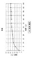
一方、乾燥運転時には、図7(c)に示すように、ダンパ76は、送風ファン74から供給された空気を吹出口72と排気口73の両方に分流する位置にある。これにより、浴室内から吸い込まれた空気は吹出口72から温風となって吹き出されると同時に、その一部は排気口73から排出される。乾燥運転時の浴室内の温度は、図10に示すグラフのように変化していくが、暖房運転開始から15分経過しても18℃程度であり、その後、徐々に昇温するものの、60分経過後においても25℃に達していないことが分かる。
On the other hand, during the drying operation, as shown in FIG. 7C, the
特許文献1などに記載された従来の浴室暖房乾燥機(浴室換気乾燥機)の場合、図7(a)に示す暖房運転時には、ダンパ76が吹出口72に向かう空気流路を閉塞する位置に設定されるため、送風ファン74から供給される空気は、排気口73に向かうことなく、全て吹出口72から温風となって吹き出される。このように、従来の浴室暖房乾燥機は、浴室内の空気を循環しながら暖房するので、比較的短時間で効率良く適正温度(25℃)まで上昇させることができる。
In the case of a conventional bathroom heating / drying machine (bathroom ventilation drying machine) described in Patent Document 1 or the like, at the time of heating operation shown in FIG. Therefore, all of the air supplied from the
一方、建築基準法の改正により、居室全体から常時一定量の換気を行うことが義務づけられているが、浴室暖房乾燥機で居室全体を換気する場合、暖房運転中は排気口を閉じて換気を中止してしまうため、一定の換気量を確保することができない。 On the other hand, due to the revision of the Building Standards Law, it is obliged to constantly ventilate the entire room from the whole room. Because it stops, it is not possible to secure a certain amount of ventilation.
本発明が解決しようとする課題は、暖房運転中においても浴室内の換気を行うことができ、且つ常時一定の換気風量と、満足できる暖房性能とを確保できる浴室暖房乾燥機を提供することにある。 The problem to be solved by the present invention is to provide a bathroom heater / dryer that can ventilate the bathroom even during heating operation, and that can ensure a constant ventilation air volume and satisfactory heating performance at all times. is there.
本発明の浴室暖房乾燥機は、浴室内の空気を吸い込んで吹出口、排気口の少なくとも一方へ供給する送風ファンと、開閉により前記送風ファンから前記吹出口、前記排気口へ供給される空気の送風および分配比率を設定するためのダンパと、前記送風ファンから供給される空気を加温して前記吹出口から吹き出すためのヒータとを備え、少なくとも暖房運転モードおよび乾燥運転モードを有する浴室暖房乾燥機であって、前記送風ファンおよびヒータが稼働する前記暖房運転モード時に前記ダンパを前記排気口が開状態となるようにするとともに、該ダンパの開度を前記乾燥運転モード時より小さい開度に設定することを特徴とする。 The bathroom heating dryer of the present invention sucks in the air in the bathroom and supplies it to at least one of the air outlet and the exhaust port, and the air supplied from the air fan to the air outlet and the exhaust port by opening and closing. A bathroom heating / drying system comprising a damper for setting the air blowing and distribution ratio, and a heater for heating the air supplied from the blower fan and blowing it out from the air outlet, having at least a heating operation mode and a drying operation mode The damper is opened in the heating operation mode in which the blower fan and the heater are operated, and the opening of the damper is smaller than that in the drying operation mode. It is characterized by setting.
このような構成とすることにより、暖房運転中、浴室内から吸い込まれた空気の一部は排気口に供給され、排気口を経由して外部へ排出されることとなるため、暖房運転中においても浴室内の換気を行うことができるようになり、満足する暖房性能を維持するとともに、一定の換気風量を確保することが可能となる。 By adopting such a configuration, during heating operation, a part of the air sucked from the bathroom is supplied to the exhaust port and discharged to the outside via the exhaust port. In addition, ventilation in the bathroom can be performed, and it is possible to maintain a satisfactory heating performance and to secure a constant ventilation air volume.
また、本発明の浴室暖房乾燥機は、浴室および/または他の居室に設けられた吸気口から空気を吸い込んで吹出口、排気口の少なくとも一方へ供給する送風ファンと、開閉により前記送風ファンから前記吹出口、前記排気口へ供給される空気の送風または分配比率を設定するダンパと、前記送風ファンから供給される空気を加温するヒータと、前記浴室および他の居室の吸気口に配設されたこれら吸気口の開度を調節するシャッタとを備え、少なくとも暖房運転モードおよび乾燥運転モードを有する浴室暖房乾燥機であって、前記送風ファンおよびヒータが稼働する前記暖房運転モード時に前記ダンパを前記排気口が開状態となるようにするとともに、該ダンパの開度を前記乾燥運転モード時より小さい開度に設定し、前記シャッタ開度を設定することを特徴とする。 In addition, the bathroom heater / dryer of the present invention includes a blower fan that sucks air from an air inlet provided in the bathroom and / or other living room and supplies the air to at least one of the air outlet and the air outlet, Arranged in the blower outlet, a damper for setting the blowing or distribution ratio of the air supplied to the exhaust port, a heater for heating the air supplied from the blower fan, and the intake ports of the bathroom and other living rooms A bathroom heater / dryer having at least a heating operation mode and a drying operation mode, wherein the damper is disposed in the heating operation mode in which the blower fan and the heater are operated. The exhaust opening is opened, the opening of the damper is set to an opening smaller than that in the dry operation mode, and the shutter opening is set. Characterized in that it.
このような構成とすれば、浴室および/または他の居室の換気および暖房を実行できるとともに、浴室および他の居室の吸気口に配設されたシャッタを移動させることで、浴室および他の居室の吸気口の吸気口の開度を調節できるため、一定の換気風量が常に維持できるよう調節でき、且つ快適な暖房を得ることができる。また、浴室のみから吸気したり、他の居室のみから吸気したり、浴室および他の居室から吸気したりすることができるため、換気したい場所や換気量の選択が可能となる。 With such a configuration, ventilation and heating of the bathroom and / or other living rooms can be performed, and the shutters disposed in the air inlets of the bathroom and other living rooms are moved to move the bathroom and other living rooms. Since the opening degree of the intake port of the intake port can be adjusted, it can be adjusted so that a constant ventilation airflow can be maintained at all times, and comfortable heating can be obtained. Moreover, since it can inhale only from a bathroom, can inhale only from another room, or can inhale from a bathroom and another room, it becomes possible to select the place to ventilate and the amount of ventilation.
ここで、前記ダンパおよび前記吸気ダンパの開度は、暖房運転中に換気風量を段階的に設定可能とすることが望ましい。このような構成とすることにより、予め決められた風量で換気できるダンパの開度を任意に設定することができるので、居室全体の面積に的確に対応した適切な風量で換気することが可能となる。 Here, it is desirable that the opening degree of the damper and the intake damper can set the ventilation air volume stepwise during the heating operation. By adopting such a configuration, it is possible to arbitrarily set the opening of the damper that can be ventilated with a predetermined air volume, so that it is possible to ventilate with an appropriate air volume that accurately corresponds to the area of the entire room. Become.
前記シャッタは、浴室側の吸気口を開閉させるべくスライド移動させることで、他の居室側の吸気口の開度を変化させる構成とすることができる。このような構成とすることにより、多室の換気量の調節が一つの機構で達成できるため浴室暖房乾燥機のコンパクト化を図ることができる。 The shutter can be configured to change the opening degree of the other air intake on the side of the room by sliding and moving the air intake on the bathroom side. By setting it as such a structure, since adjustment of the ventilation volume of multiple rooms can be achieved by one mechanism, the bathroom heating dryer can be made compact.
本発明の浴室暖房乾燥機により、暖房運転中においても、一定の換気風量を維持しつつ満足のいく暖房性能を確保することができる。 The bathroom heater / dryer of the present invention can ensure satisfactory heating performance while maintaining a constant ventilation air volume even during heating operation.
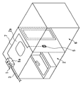
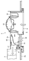
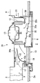
以下、図面に基づいて、本発明の実施の形態である浴室暖房乾燥機について説明する。図1は本発明の第1実施形態である浴室暖房乾燥機を浴室に設置した状態を示す斜視図であり、図2,図3は図1に示す浴室暖房乾燥機の垂直断面図である。 Hereinafter, a bathroom heating dryer according to an embodiment of the present invention will be described with reference to the drawings. FIG. 1 is a perspective view showing a state in which a bathroom heater / dryer according to a first embodiment of the present invention is installed in a bathroom, and FIGS. 2 and 3 are vertical sectional views of the bathroom heater / dryer shown in FIG.
図1に示すように、本実施形態の浴室暖房乾燥機1は浴室2の天井2aに配置され、本体ケーシング1aに排気ダクト3が連結されている。また、浴室暖房乾燥機1を操作するためのリモコン部5が脱衣場6の壁面に配置され、リモコン部5と浴室暖房乾燥機1との間には制御用の配線7が設けられている。
As shown in FIG. 1, the bathroom heating / drying machine 1 of this embodiment is arrange | positioned at the
図2に示すように、浴室暖房乾燥機1においては、本体ケーシング1aに、吸気口8、排気口9、吹出口10が設けられ、排気口9には排気ダクト3が接続されている。また、本体ケーシング1aの内部には、モータ13で駆動される送風ファン12と、送風ファン12から吹出口10に供給される空気を加温するためのヒータ14と、送風ファン12から吹出口10、排気口9へ供給される空気の分配比率を設定するためのダンパ15とが設けられている。ダンパ15は、空気流路17に、支軸15aを中心に揺動可能に配置されている。
As shown in FIG. 2, in the bathroom heater / dryer 1, a
浴室暖房乾燥機1を暖房運転させる場合、図2に示すように、乾燥運転時に設定させたダンパ15の開度と、従来の暖房運転時に設定させたダンパ15の閉状態のときとの中間位置より更に排気口9側に寄せた位置(排気口9が少し開状態となる位置)にダンパ15が設定される。したがって、送風ファン12の作用により吸気口8から吸い込まれ外気流路17に送り込まれる空気は、ダンパ15で二方向に分流され、一方は排気口9に向かって流れ、他方は吹出口10に向かって流れる。排気口9に向かって流れた空気は排気ダクト3へ流れ込み、その後、屋外へ排出される。吹出口10に向かって流れた空気はヒータ14によって加温され温風となって吹出口10から浴室2へ吹き出す。
When heating the bathroom heating / drying machine 1, as shown in FIG. 2, an intermediate position between the opening of the
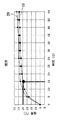
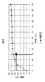
このように、暖房運転中、浴室2内から吸い込まれた空気は、温風となって吹出口10から吹き出すとともに、その一部は排気口9を経由して屋外へ排出されるため、暖房運転中においても浴室2内の換気を行うことができる。浴室暖房乾燥機1を図2に示すような暖房モードで運転したとき、運転開始後の浴室2の温度変化を測定すると、図8に示すグラフの折れ線19のような結果が得られた。折れ線19は、運転開始から15分経過時に一般的に人が暖房効果が得られたとして認める25℃まで昇温し、その後も25℃〜30℃の範囲内で僅かながら昇温している。
Thus, during the heating operation, the air sucked from the
このように、浴室暖房乾燥機1を暖房運転させた場合、運転開始後15分が経過した時点で浴室2内の温度は25℃に達しているため、浴室暖房乾燥機1は実用上問題のない暖房性能を有していることが判る。
Thus, when the bathroom heating / drying machine 1 is operated for heating, the temperature in the
図8に示すグラフの折れ線20は、従来の浴室暖房乾燥機をダンパ15が閉状態を維持したままで暖房運転した場合の浴室の温度変化を示すものである。従来の浴室暖房乾燥機をダンパ15が閉状態のままで暖房運転させた場合、運転開始から10分経過した時に、一般的に人が暖房効果が得られたとして認める25℃まで昇温し、その後も僅かながら昇温している。
The
図8に示すグラフの折れ線19,20を比較すると、どちらも25℃を超えると温度上昇率は小さくなり、折れ線19,20はいずれも横ばいとなっている。これはヒータの能力限界によるもので、加熱時間を長くしても温度を上げることはできない。そのため、要求以上の暖房温度を長時間続けることは省エネを考えると好ましくない。
Comparing the
従って、ダンパ15の開度は、浴室暖房乾燥機1を配置した室内温度が25℃となる経過点を確保でき、且つ25℃以上を維持可能な開度に設定することが最も好ましい。そして、このようなダンパ開度に設定することにより、無駄なエネルギーを使うことなく、満足のいく暖房性能を得ることができ、且つ常時一定換気風量をも確保することができる。
Therefore, it is most preferable that the opening degree of the
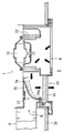
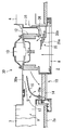
一方、ダンパ15は支軸15aを中心に揺動可能であるため、浴室暖房乾燥機1を暖房運転させる場合においても、図3に示すように、ダンパ15の位置を変更することにより、送風ファン12から吹出口10、排気口9へ供給される空気の分配比率を変更することできる。すなわち、浴室2の大きさ等により換気量を定めるダンパ15の位置を変化させることで、排気口9から排出される換気用の空気量を調整することができる。
On the other hand, since the
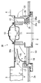
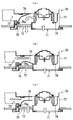
次に、図4〜図6を参照して、本発明の第2実施形態である浴室暖房乾燥機について説明する。図4〜図6は本発明の第2実施形態である浴室暖房乾燥機30を示す垂直断面図である。
Next, with reference to FIGS. 4-6, the bathroom heating dryer which is 2nd Embodiment of this invention is demonstrated. 4 to 6 are vertical sectional views showing a bathroom heater /
図4に示すように、本実施形態の浴室暖房乾燥機30においては、本体ケーシング30aに吸気口8、排気口9、吹出口10および吸気口31が設けられ、排気口9に排気ダクト3が接続され、他の居室と連通する吸気口31に吸気ダクト4が接続されている。また、本体ケーシング30aの内部には、モータ13で駆動される送風ファン12と、送風ファン12から吹出口10に供給される空気を加温するためのヒータ14と、送風ファン12から吹出口10、排気口9へ供給される空気の分配比率を設定するためのダンパ15と、が設けられている。ダンパ15は、空気流路17に、支軸15aを中心に揺動可能に配置されている。
As shown in FIG. 4, in the bathroom heating /
一方、本体ケーシング30aに設けられた、浴室以外の他の居室と連通する吸気口31の内側部分には、吸気路36と、この吸気路36を開閉するためのシャッタ35とが設けられている。シャッタ35は、本体ケーシング30aの内面に水平方向に延設された棚状部材35b上に積層状態に配置された複数の平板材35aと、これらの平板材35aを水平方向にスライド可能に保持する連結機構(図示せず)とによって形成されている。シャッタ35は複数の平板材35aを水平方向にスライドさせることにより、浴室2側の吸気口8および浴室以外の他の居室と連通する吸気口31を開閉することができる。
On the other hand, an
浴室2のみを暖房するために浴室暖房乾燥機30を運転させる場合、図4に示すように、シャッタ35を棚状部材35b上に積層状態に収納することによって吸気路36を閉塞すると、送風ファン12により吸気口8から吸い込まれて外気流路17に送り込まれる空気が、排気口9および吹出口10の両方へ供給される。このとき、乾燥運転時に設定させたダンパ15の開度と、従来の暖房運転時に設定させたダンパ15の閉となった状態との中間位置より更に排気口9側に寄せた位置(排気口9が少し開となる位置)にダンパ15が設定される。
When the bathroom heater /
この状態で、送風ファン12およびヒータ14を作動させると、送風ファン12の作用により吸気口8から吸い込まれ外気流路17に送り込まれる空気は、ダンパ15で二方向に分流され、一方は排気口9に向かって流れ、他方は吹出口10に向かって流れる。排気口9に向かって流れた空気は排気ダクト3へ流れ込み、その後、屋外へ排出される。吹出口10に向かって流れた空気はヒータ14によって加温され温風となって吹出口10から浴室2へ吹き出され、浴室2の暖房に供される。
When the
次に、図5に示すように、シャッタ35を水平方向にスライドさせて吸気口8を閉塞するとともに吸気路36を開放した状態で、送風ファン12およびヒータ14を作動させると、吸気口31を経由して他の居室からの空気が吸気路36に流れ込み、送風ファン12を経て空気流路17へ供給される空気は、ダンパ15で二方向に分流され、一方は排気口9に向かって流れ、他方は吹出口10に向かって流れる。
Next, as shown in FIG. 5, when the
排気口9に向かって流れた空気は排気ダクト3へ流れ込み、その後、屋外へ排出され、吹出口10に向かって流れた空気はヒータ14によって加温され温風となって吹出口10から浴室2へ吹き出され、浴室2の暖房に供される。このように、図5に示す状態にシャッタ35をセットして送風ファン12およびヒータ14を作動させることにより、浴室2の暖房を行うと同時に他の居室の換気とを行うことができる。
The air that flows toward the
これにより、暖房運転時においても、浴室2側からは換気されず、他の居室から換気されるので、一定の換気風量は常に確保することができる。また、浴室2は換気されないので、浴室2においては満足のいく暖房性能を得ることができる。
Thus, even during the heating operation, ventilation is not performed from the
次に、図6に示すように、シャッタ35を水平方向に半分程度スライドさせて吸気口8を半開状態にするとともに吸気路36も半開した状態で、送風ファン12およびヒータ14を作動させると、吸気口8から浴室2の空気が吸い込まれるとともに、他の居室からの空気が吸気口31を経由して吸気路36に流れ込み、送風ファン12を経て空気流路17へ供給される。
Next, as shown in FIG. 6, when the
空気流路17へ送られた空気は、ダンパ15で二方向に分流され、一方は排気口9に向かって流れ、他方は吹出口10に向かって流れる。排気口9に向かって流れた空気は排気ダクト3へ流れ込み、その後、屋外へ排出され、吹出口10に向かって流れた空気はヒータ14によって加温され温風となって吹出口10から浴室2へ吹き出され、浴室2の暖房に供される。
The air sent to the
このように、図6に示す半開状態にシャッタ35をセットして送風ファン12およびヒータ14を作動させることにより、浴室2の暖房および換気を行うと同時に他の居室の換気とを行うことができる。すなわち、浴室2および他の居室の両方の換気を並行して行うことができる。
In this way, by setting the
また、浴室暖房乾燥機30においては、シャッタ35の浴室2および/または他の居室の吸気口31の開度を変更したり、ダンパ15の開度位置を変更したりすることにより、居室全体の面積の違いに応じて換気風量を効率良く調節することができるため、居室全体の面積に的確に対応した適切な換気風量を設定することができ、且つ満足のいく暖房性能を得ることができる。
In the bathroom heater /
本発明の浴室暖房乾燥機は、戸建て住宅や集合住宅などに設けられた浴室内を換気、暖房する装置として利用することができる。 The bathroom heater / dryer of the present invention can be used as a device for ventilating and heating the interior of a bathroom provided in a detached house or an apartment house.
1,30 浴室暖房乾燥機
1a,30a 本体ケーシング
2 浴室
2a 天井
3 排気ダクト
4 吸気ダクト
5 リモコン部
6 脱衣場
7 配線
8,31 吸気口
9 排気口
10 吹出口
12 送風ファン
13 モータ
14 ヒータ
15 ダンパ
17 空気流路
19,20 折れ線
35 シャッタ
35a 板材
35b 棚状部材
36 吸気路
DESCRIPTION OF
Claims (4)
4. The bathroom heating according to claim 2, wherein the shutter is configured to change an opening degree of the air inlet on the other room side by sliding to open and close the air inlet on the bathroom side. 5. Dryer.
Priority Applications (1)
| Application Number | Priority Date | Filing Date | Title |
|---|---|---|---|
| JP2004106005A JP2005291604A (en) | 2004-03-31 | 2004-03-31 | Bathroom heating and drying machine |
Applications Claiming Priority (1)
| Application Number | Priority Date | Filing Date | Title |
|---|---|---|---|
| JP2004106005A JP2005291604A (en) | 2004-03-31 | 2004-03-31 | Bathroom heating and drying machine |
Publications (1)
| Publication Number | Publication Date |
|---|---|
| JP2005291604A true JP2005291604A (en) | 2005-10-20 |
Family
ID=35324726
Family Applications (1)
| Application Number | Title | Priority Date | Filing Date |
|---|---|---|---|
| JP2004106005A Pending JP2005291604A (en) | 2004-03-31 | 2004-03-31 | Bathroom heating and drying machine |
Country Status (1)
| Country | Link |
|---|---|
| JP (1) | JP2005291604A (en) |
Cited By (4)
| Publication number | Priority date | Publication date | Assignee | Title |
|---|---|---|---|---|
| JP2010164262A (en) * | 2009-01-16 | 2010-07-29 | Mitsubishi Electric Corp | Ventilating device |
| JP2011017485A (en) * | 2009-07-09 | 2011-01-27 | Toto Ltd | Bathroom drying machine |
| JP2014001879A (en) * | 2012-06-18 | 2014-01-09 | Mitsubishi Electric Corp | Bathroom dryer |
| JP2018141590A (en) * | 2017-02-28 | 2018-09-13 | パナソニックIpマネジメント株式会社 | Bathroom heating dryer |
-
2004
- 2004-03-31 JP JP2004106005A patent/JP2005291604A/en active Pending
Cited By (4)
| Publication number | Priority date | Publication date | Assignee | Title |
|---|---|---|---|---|
| JP2010164262A (en) * | 2009-01-16 | 2010-07-29 | Mitsubishi Electric Corp | Ventilating device |
| JP2011017485A (en) * | 2009-07-09 | 2011-01-27 | Toto Ltd | Bathroom drying machine |
| JP2014001879A (en) * | 2012-06-18 | 2014-01-09 | Mitsubishi Electric Corp | Bathroom dryer |
| JP2018141590A (en) * | 2017-02-28 | 2018-09-13 | パナソニックIpマネジメント株式会社 | Bathroom heating dryer |
Similar Documents
| Publication | Publication Date | Title |
|---|---|---|
| CN110023686B (en) | Heat exchange type ventilator | |
| WO2012127663A1 (en) | Bathroom dryer | |
| WO2012127662A1 (en) | Bathroom dryer | |
| JP4801022B2 (en) | Bathroom air conditioner with mist function | |
| JP2005291604A (en) | Bathroom heating and drying machine | |
| JP4354415B2 (en) | Heat exchange ventilator | |
| JP2005241160A (en) | Bathroom ventilating heating drying device | |
| JP3959181B2 (en) | Heat exchange ventilation system | |
| JP2004045016A (en) | Bath room heater with ventilating function | |
| JP2001108271A (en) | Ventilating device, air conditioning and ventilating system as well as building employing the ventilating device | |
| CN104748194B (en) | Bathroom air-conditioning system | |
| JP3959182B2 (en) | Heat exchange ventilation system | |
| JP4372698B2 (en) | Embedded ceiling heat exchange ventilator | |
| JP4463704B2 (en) | Damper device and heat exchange ventilator equipped with damper device | |
| JP4050680B2 (en) | Bathroom heating system | |
| JP2004257605A (en) | Bathroom ventilation, heating, and drying apparatus | |
| JP2005164114A (en) | Bathroom air conditioning system | |
| JP2563127B2 (en) | Indoor air circulation equipment | |
| JP2956468B2 (en) | Multi-room ventilation method, multi-room ventilation device and multi-room ventilation system | |
| JP4311036B2 (en) | Bathroom ventilation heating dryer | |
| KR100687054B1 (en) | Ventilation device and its operation method | |
| JP2006046685A (en) | Bathroom air conditioner | |
| JP2007024407A (en) | Residential ventilation system | |
| JP4857194B2 (en) | Bathroom heating system | |
| JP4304402B2 (en) | Bathroom ventilator |