JP2005291584A - Air-conditioning system - Google Patents

Air-conditioning system Download PDF

Info

Publication number
JP2005291584A
JP2005291584A JP2004105174A JP2004105174A JP2005291584A JP 2005291584 A JP2005291584 A JP 2005291584A JP 2004105174 A JP2004105174 A JP 2004105174A JP 2004105174 A JP2004105174 A JP 2004105174A JP 2005291584 A JP2005291584 A JP 2005291584A
Authority
JP
Japan
Prior art keywords
air
heat
sensible heat
adsorption
refrigerant
Prior art date
Legal status (The legal status is an assumption and is not a legal conclusion. Google has not performed a legal analysis and makes no representation as to the accuracy of the status listed.)
Granted
Application number
JP2004105174A
Other languages
Japanese (ja)
Other versions
JP3709482B2 (en
Inventor
Ryusuke Fujiyoshi
竜介 藤吉
Tomohiro Yabu
知宏 薮
Current Assignee (The listed assignees may be inaccurate. Google has not performed a legal analysis and makes no representation or warranty as to the accuracy of the list.)
Daikin Industries Ltd
Original Assignee
Daikin Industries Ltd
Priority date (The priority date is an assumption and is not a legal conclusion. Google has not performed a legal analysis and makes no representation as to the accuracy of the date listed.)
Filing date
Publication date
Priority to JP2004105174A priority Critical patent/JP3709482B2/en
Application filed by Daikin Industries Ltd filed Critical Daikin Industries Ltd
Priority to CN2008101694298A priority patent/CN101403517B/en
Priority to US10/591,055 priority patent/US7395677B2/en
Priority to EP05721316A priority patent/EP1736710A4/en
Priority to CNB200580006653XA priority patent/CN100473913C/en
Priority to KR1020067018129A priority patent/KR100720813B1/en
Priority to AU2005230499A priority patent/AU2005230499B2/en
Priority to PCT/JP2005/005266 priority patent/WO2005098321A1/en
Publication of JP2005291584A publication Critical patent/JP2005291584A/en
Application granted granted Critical
Publication of JP3709482B2 publication Critical patent/JP3709482B2/en
Anticipated expiration legal-status Critical
Expired - Fee Related legal-status Critical Current

Links

Images

Classifications

    • FMECHANICAL ENGINEERING; LIGHTING; HEATING; WEAPONS; BLASTING
    • F24HEATING; RANGES; VENTILATING
    • F24FAIR-CONDITIONING; AIR-HUMIDIFICATION; VENTILATION; USE OF AIR CURRENTS FOR SCREENING
    • F24F3/00Air-conditioning systems in which conditioned primary air is supplied from one or more central stations to distributing units in the rooms or spaces where it may receive secondary treatment; Apparatus specially designed for such systems
    • F24F3/06Air-conditioning systems in which conditioned primary air is supplied from one or more central stations to distributing units in the rooms or spaces where it may receive secondary treatment; Apparatus specially designed for such systems characterised by the arrangements for the supply of heat-exchange fluid for the subsequent treatment of primary air in the room units
    • F24F3/065Air-conditioning systems in which conditioned primary air is supplied from one or more central stations to distributing units in the rooms or spaces where it may receive secondary treatment; Apparatus specially designed for such systems characterised by the arrangements for the supply of heat-exchange fluid for the subsequent treatment of primary air in the room units with a plurality of evaporators or condensers
    • FMECHANICAL ENGINEERING; LIGHTING; HEATING; WEAPONS; BLASTING
    • F24HEATING; RANGES; VENTILATING
    • F24FAIR-CONDITIONING; AIR-HUMIDIFICATION; VENTILATION; USE OF AIR CURRENTS FOR SCREENING
    • F24F11/00Control or safety arrangements
    • F24F11/30Control or safety arrangements for purposes related to the operation of the system, e.g. for safety or monitoring
    • F24F11/41Defrosting; Preventing freezing
    • FMECHANICAL ENGINEERING; LIGHTING; HEATING; WEAPONS; BLASTING
    • F24HEATING; RANGES; VENTILATING
    • F24FAIR-CONDITIONING; AIR-HUMIDIFICATION; VENTILATION; USE OF AIR CURRENTS FOR SCREENING
    • F24F3/00Air-conditioning systems in which conditioned primary air is supplied from one or more central stations to distributing units in the rooms or spaces where it may receive secondary treatment; Apparatus specially designed for such systems
    • F24F3/12Air-conditioning systems in which conditioned primary air is supplied from one or more central stations to distributing units in the rooms or spaces where it may receive secondary treatment; Apparatus specially designed for such systems characterised by the treatment of the air otherwise than by heating and cooling
    • F24F3/14Air-conditioning systems in which conditioned primary air is supplied from one or more central stations to distributing units in the rooms or spaces where it may receive secondary treatment; Apparatus specially designed for such systems characterised by the treatment of the air otherwise than by heating and cooling by humidification; by dehumidification
    • F24F3/1411Air-conditioning systems in which conditioned primary air is supplied from one or more central stations to distributing units in the rooms or spaces where it may receive secondary treatment; Apparatus specially designed for such systems characterised by the treatment of the air otherwise than by heating and cooling by humidification; by dehumidification by absorbing or adsorbing water, e.g. using an hygroscopic desiccant
    • F24F3/1429Air-conditioning systems in which conditioned primary air is supplied from one or more central stations to distributing units in the rooms or spaces where it may receive secondary treatment; Apparatus specially designed for such systems characterised by the treatment of the air otherwise than by heating and cooling by humidification; by dehumidification by absorbing or adsorbing water, e.g. using an hygroscopic desiccant alternatively operating a heat exchanger in an absorbing/adsorbing mode and a heat exchanger in a regeneration mode
    • FMECHANICAL ENGINEERING; LIGHTING; HEATING; WEAPONS; BLASTING
    • F25REFRIGERATION OR COOLING; COMBINED HEATING AND REFRIGERATION SYSTEMS; HEAT PUMP SYSTEMS; MANUFACTURE OR STORAGE OF ICE; LIQUEFACTION SOLIDIFICATION OF GASES
    • F25BREFRIGERATION MACHINES, PLANTS OR SYSTEMS; COMBINED HEATING AND REFRIGERATION SYSTEMS; HEAT PUMP SYSTEMS
    • F25B13/00Compression machines, plants or systems, with reversible cycle
    • FMECHANICAL ENGINEERING; LIGHTING; HEATING; WEAPONS; BLASTING
    • F24HEATING; RANGES; VENTILATING
    • F24FAIR-CONDITIONING; AIR-HUMIDIFICATION; VENTILATION; USE OF AIR CURRENTS FOR SCREENING
    • F24F3/00Air-conditioning systems in which conditioned primary air is supplied from one or more central stations to distributing units in the rooms or spaces where it may receive secondary treatment; Apparatus specially designed for such systems
    • F24F3/12Air-conditioning systems in which conditioned primary air is supplied from one or more central stations to distributing units in the rooms or spaces where it may receive secondary treatment; Apparatus specially designed for such systems characterised by the treatment of the air otherwise than by heating and cooling
    • F24F3/14Air-conditioning systems in which conditioned primary air is supplied from one or more central stations to distributing units in the rooms or spaces where it may receive secondary treatment; Apparatus specially designed for such systems characterised by the treatment of the air otherwise than by heating and cooling by humidification; by dehumidification
    • F24F2003/1458Air-conditioning systems in which conditioned primary air is supplied from one or more central stations to distributing units in the rooms or spaces where it may receive secondary treatment; Apparatus specially designed for such systems characterised by the treatment of the air otherwise than by heating and cooling by humidification; by dehumidification using regenerators
    • FMECHANICAL ENGINEERING; LIGHTING; HEATING; WEAPONS; BLASTING
    • F24HEATING; RANGES; VENTILATING
    • F24FAIR-CONDITIONING; AIR-HUMIDIFICATION; VENTILATION; USE OF AIR CURRENTS FOR SCREENING
    • F24F2110/00Control inputs relating to air properties
    • F24F2110/10Temperature
    • F24F2110/12Temperature of the outside air
    • FMECHANICAL ENGINEERING; LIGHTING; HEATING; WEAPONS; BLASTING
    • F25REFRIGERATION OR COOLING; COMBINED HEATING AND REFRIGERATION SYSTEMS; HEAT PUMP SYSTEMS; MANUFACTURE OR STORAGE OF ICE; LIQUEFACTION SOLIDIFICATION OF GASES
    • F25BREFRIGERATION MACHINES, PLANTS OR SYSTEMS; COMBINED HEATING AND REFRIGERATION SYSTEMS; HEAT PUMP SYSTEMS
    • F25B2313/00Compression machines, plants or systems with reversible cycle not otherwise provided for
    • F25B2313/023Compression machines, plants or systems with reversible cycle not otherwise provided for using multiple indoor units

Abstract

<P>PROBLEM TO BE SOLVED: To restrain a cost increase caused by arranging a plurality of air conditioners using an adsorption heat exchanger and a size increase in a unit with built-in adsorption heat exchanger. <P>SOLUTION: This air-conditioning system 1 has a plurality of using units 2 and 3, a heat source unit 6, and connecting pipes 7 and 8 for connecting mutual both units, and treats an indoor latent heat load and a sensible heat load. The using unit 2 has the adsorption heat exchangers 22 and 23 for arranging an adsorbent on a surface, and can alternately perform adsorbing operation for adsorbing moisture in the air in the adsorbent by making its one function as an evaporator of a refrigerant and regenerating operation for separating the moisture from the adsorbent by making its other function as a condenser of the refrigerant. The using unit 3 has the adsorption heat exchangers 32 and 33 for arranging the adsorbent on a surface, and can also perform the adsorbing operation and the regenerating operation similar to the using unit 2. The heat source unit 6 has a compression mechanism 11 and an accumulator 62. <P>COPYRIGHT: (C)2006,JPO&NCIPI

Description

本発明は、空気調和システム、特に、蒸気圧縮式の冷凍サイクル運転を行うことによって、屋内の潜熱負荷及び顕熱負荷を処理する空気調和システムに関する。   The present invention relates to an air conditioning system, and more particularly to an air conditioning system that processes indoor latent heat load and sensible heat load by performing a vapor compression refrigeration cycle operation.

従来より、屋内の冷房と除湿を行う空気調和装置が知られている(例えば、特許文献1参照。)。このような空気調和装置は、熱源側熱交換器としての室外熱交換器と空気熱交換器としての室内熱交換器とを有する蒸気圧縮式の冷媒回路を備えており、この冷媒回路内に冷媒を循環させて冷凍サイクル運転を行う。そして、この空気調和装置は、室内熱交換器における冷媒の蒸発温度を室内空気の露点温度よりも低く設定し、屋内の空気中の水分を凝縮させることで屋内の除湿を行っている。   Conventionally, an air conditioner that performs indoor cooling and dehumidification is known (see, for example, Patent Document 1). Such an air conditioner includes a vapor compression refrigerant circuit having an outdoor heat exchanger as a heat source side heat exchanger and an indoor heat exchanger as an air heat exchanger, and the refrigerant circuit includes a refrigerant. Refrigeration cycle operation by circulating This air conditioner dehumidifies indoors by setting the evaporation temperature of the refrigerant in the indoor heat exchanger to be lower than the dew point temperature of the indoor air and condensing the moisture in the indoor air.

一方、表面に吸着剤が設けられた熱交換器を備えた除湿装置も知られている(例えば、特許文献2参照。)。このような除湿装置は、吸着剤が設けられた2つの熱交換器を備えており、2つの熱交換器の一方において空気中の水分を吸着して除湿する吸着動作を行い、2つの熱交換器の他方において吸着された水分を脱離させる再生動作を行う。その際、水分を吸着する方の熱交換器には冷却塔で冷却された水が供給され、再生される熱交換器には温排水が供給される。そして、この除湿装置は、吸着動作及び再生動作によって除湿された空気を屋内へ供給するようになっている。
国際公開第03/029728号パンフレット 特開平7−265649号公報
On the other hand, a dehumidifying device including a heat exchanger having an adsorbent on the surface is also known (see, for example, Patent Document 2). Such a dehumidifying apparatus includes two heat exchangers provided with an adsorbent, and performs an adsorption operation in which moisture in the air is adsorbed and dehumidified in one of the two heat exchangers. A regenerating operation for desorbing moisture adsorbed on the other side of the vessel is performed. At that time, water cooled by the cooling tower is supplied to the heat exchanger that adsorbs moisture, and hot waste water is supplied to the regenerated heat exchanger. And this dehumidification apparatus supplies the air dehumidified by adsorption | suction operation | movement and reproduction | regeneration operation | movement indoors.
International Publication No. 03/029728 Pamphlet JP-A-7-265649

上記前者の空気調和装置では、室内熱交換器での冷媒蒸発温度を屋内の空気の露点温度よりも低く設定し、空気中の水分を凝縮させることで屋内の潜熱負荷を処理している。つまり、室内熱交換器での冷媒の蒸発温度が屋内の空気の露点温度よりも高くても顕熱負荷の処理は可能であるが、その分だけ、潜熱負荷を処理するために室内熱交換器での冷媒の蒸発温度を低い値に設定しなければならなくなっている。このため、蒸気圧縮式の冷凍サイクルの高低圧差が大きくなり、圧縮機における消費動力が大きくなり、低いCOP(成績係数)しか得られないという問題があった。   In the former air conditioner, the refrigerant evaporating temperature in the indoor heat exchanger is set lower than the dew point temperature of indoor air, and the indoor latent heat load is processed by condensing moisture in the air. That is, even if the evaporation temperature of the refrigerant in the indoor heat exchanger is higher than the dew point temperature of the indoor air, the sensible heat load can be processed, but the indoor heat exchanger is used to process the latent heat load accordingly. It has become necessary to set the evaporation temperature of the refrigerant at a low value. For this reason, there is a problem that the difference between high and low pressures of the vapor compression refrigeration cycle is increased, the power consumption in the compressor is increased, and only a low COP (coefficient of performance) can be obtained.

また、上記後者の除湿装置では、冷却塔で冷却された冷却水、すなわち、屋内の温度に比べてそれほど温度の低くない冷却水を熱交換器へ供給している。したがって、この除湿装置では、屋内の潜熱負荷は処理できても顕熱負荷を処理できないという問題があった。
これに対して、本願発明者は、熱源側熱交換器と利用側熱交換器としての吸着熱交換器とを有する蒸気圧縮式の冷媒回路を備えた空気調和装置を発明している(例えば、特願2003−351268号参照。)。この空気調和装置は、表面に吸着剤が設けられた吸着熱交換器に空気中の水分を吸着させる吸着動作と吸着熱交換器から水分を脱離させる再生動作とを交互に行い、吸着熱交換器を通過した空気を屋内へ供給して屋内の顕熱負荷及び潜熱負荷を処理することができるものである。つまり、上記前者の空気調和装置のように空気中の水分を凝縮させて空気を除湿するのではなく、空気中の水分を吸着剤に吸着させて空気を除湿しているため、冷媒の蒸発温度を空気の露点温度よりも低く設定する必要がなく、冷媒の蒸発温度を空気の露点温度以上に設定しても空気の除湿が可能となる。このため、この空気調和装置によれば、空気を除湿する場合も冷媒の蒸発温度を従来よりも高い温度に設定することができ、冷凍サイクルの高低圧差を縮小することができる。この結果、圧縮機における消費動力を減らすことが可能となり、COPを向上させることができる。また、空気の除湿を行う場合に、吸着熱交換器において必要な冷媒の蒸発温度よりも低い温度に設定することによって、その屋内の顕熱負荷も併せて処理することができる。
In the latter dehumidifier, the cooling water cooled by the cooling tower, that is, the cooling water having a temperature not much lower than the indoor temperature is supplied to the heat exchanger. Therefore, this dehumidifier has a problem that the sensible heat load cannot be processed even if the indoor latent heat load can be processed.
In contrast, the inventor of the present application has invented an air conditioner including a vapor compression refrigerant circuit having a heat source side heat exchanger and an adsorption heat exchanger as a use side heat exchanger (for example, (See Japanese Patent Application No. 2003-351268.) This air conditioner performs adsorption heat exchange by alternately performing an adsorption operation for adsorbing moisture in the air to an adsorption heat exchanger with an adsorbent on the surface and a regeneration operation for desorbing moisture from the adsorption heat exchanger. The air passing through the vessel can be supplied indoors to handle indoor sensible heat load and latent heat load. That is, instead of condensing the moisture in the air and dehumidifying the air as in the former air conditioner, the moisture in the air is adsorbed by the adsorbent to dehumidify the air, so the evaporation temperature of the refrigerant Need not be set lower than the dew point temperature of the air, and the air can be dehumidified even if the evaporation temperature of the refrigerant is set higher than the dew point temperature of the air. For this reason, according to this air conditioning apparatus, even when air is dehumidified, the evaporation temperature of the refrigerant can be set to a higher temperature than before, and the high / low pressure difference of the refrigeration cycle can be reduced. As a result, power consumption in the compressor can be reduced, and COP can be improved. Moreover, when dehumidifying air, by setting the temperature lower than the evaporation temperature of the refrigerant necessary in the adsorption heat exchanger, the indoor sensible heat load can also be processed.

そして、本願発明者は、上記の吸着熱交換器を用いた空気調和装置をビル等の建物に設置される空気調和システム(いわゆる、マルチ空気調和システム)に適用しようとしているが、このような大規模な空気調和システムにおいては、上記の吸着熱交換器を用いた空気調和装置を複数台設置しなければならないため、吸着熱交換器の数に応じて熱源としての圧縮機を設置しなければならなくなり、コストアップ及びメンテナンス箇所が多くなるという問題点が生じてしまう。しかも、空気調和装置の運転負荷の変動に伴う冷媒循環量の増減により各空気調和装置の冷媒回路内に余剰冷媒が生じるため、冷媒循環量の減少に伴って発生する余剰冷媒を溜めるためのレシーバを吸着熱交換器の数に対応して接続しなければならなくなり、さらなるコストアップや吸着熱交換器を内蔵するユニットのサイズが大きくなるという問題が生じてしまう。   The inventor of the present application intends to apply an air conditioning apparatus using the above-described adsorption heat exchanger to an air conditioning system (a so-called multi-air conditioning system) installed in a building such as a building. In a large-scale air conditioning system, it is necessary to install a plurality of air conditioners using the adsorption heat exchanger described above, so a compressor as a heat source must be installed according to the number of adsorption heat exchangers. This causes problems that the cost increases and the number of maintenance points increases. In addition, since a surplus refrigerant is generated in the refrigerant circuit of each air conditioner due to an increase or decrease in the refrigerant circulation amount due to fluctuations in the operating load of the air conditioner, a receiver for accumulating surplus refrigerant generated as the refrigerant circulation amount decreases. Must be connected in accordance with the number of adsorption heat exchangers, resulting in further cost increase and an increase in the size of the unit containing the adsorption heat exchanger.

本発明の課題は、吸着熱交換器を用いた空気調和装置を複数台設置する際に生じるコストアップや吸着熱交換器を内蔵するユニットのサイズが大きくなるのを抑えることにある。   The subject of this invention is suppressing the increase in the cost which arises when installing several air conditioning apparatuses using an adsorption heat exchanger, and the size of the unit which incorporates an adsorption heat exchanger.

第1の発明にかかる空気調和システムは、蒸気圧縮式の冷凍サイクル運転を行うことによって、屋内の潜熱負荷及び顕熱負荷を処理する空気調和システムであって、複数の利用側冷媒回路と、熱源側冷媒回路と、吐出ガス連絡配管と、吸入ガス連絡配管とを備えている。利用側冷媒回路は、表面に吸着剤が設けられた2つの吸着熱交換器を有しており、2つの吸着熱交換器の一方を冷媒の蒸発器として機能させて空気中の水分を吸着剤に吸着させる吸着動作と、2つの吸着熱交換器の他方を冷媒の凝縮器として機能させて前記吸着剤から水分を脱離させる再生動作とを2つの吸着熱交換器の間で交互に行うことで空気を除湿又は加湿することが可能である。熱源側冷媒回路は、圧縮機構と、圧縮機構の吸入側に接続される液溜容器とを有する。吐出ガス連絡配管は、圧縮機構の吐出側に接続されており、利用側冷媒回路と熱源側冷媒回路とを接続する。吸入ガス連絡配管は、圧縮機構の吸入側に接続される。空気調和システムは、吸着熱交換器を通過した空気を屋内に供給することが可能である。   An air conditioning system according to a first aspect of the present invention is an air conditioning system that processes an indoor latent heat load and a sensible heat load by performing a vapor compression refrigeration cycle operation, and includes a plurality of usage-side refrigerant circuits, a heat source A side refrigerant circuit, a discharge gas communication pipe, and an intake gas communication pipe are provided. The usage-side refrigerant circuit has two adsorption heat exchangers with adsorbents on the surface, and allows one of the two adsorption heat exchangers to function as a refrigerant evaporator to remove moisture in the air. The adsorption operation to be adsorbed on and the regeneration operation to desorb moisture from the adsorbent by causing the other of the two adsorption heat exchangers to function as a refrigerant condenser are alternately performed between the two adsorption heat exchangers. It is possible to dehumidify or humidify the air. The heat source side refrigerant circuit has a compression mechanism and a liquid reservoir connected to the suction side of the compression mechanism. The discharge gas communication pipe is connected to the discharge side of the compression mechanism, and connects the use side refrigerant circuit and the heat source side refrigerant circuit. The suction gas communication pipe is connected to the suction side of the compression mechanism. The air conditioning system can supply the air that has passed through the adsorption heat exchanger indoors.

この空気調和システムでは、吸着熱交換器の吸着動作及び再生動作を交互に行うことで吸着熱交換器を通過する空気を除湿又は加湿することによって主として屋内の潜熱負荷を処理することが可能な複数の利用側冷媒回路が、吐出ガス連絡配管及び吸入ガス連絡配管を介して熱源側冷媒回路に接続されることによって、いわゆる、マルチ空気調和システムを構成している。つまり、利用側冷媒回路との間で蒸気圧縮式の冷凍サイクル運転を行うための熱源を複数の利用側冷媒回路に共通の1つの熱源にまとめるようにしている。これにより、吸着熱交換器を用いた空気調和装置を複数台設置する際に生じるコストアップやメンテナンス箇所の増加を抑えることができる。   In this air conditioning system, a plurality of indoor heat latent loads can be mainly processed by dehumidifying or humidifying the air passing through the adsorption heat exchanger by alternately performing the adsorption operation and the regeneration operation of the adsorption heat exchanger. The use side refrigerant circuit is connected to the heat source side refrigerant circuit via the discharge gas communication pipe and the intake gas communication pipe, thereby forming a so-called multi-air conditioning system. That is, the heat source for performing the vapor compression refrigeration cycle operation with the use side refrigerant circuit is combined into one heat source common to the plurality of use side refrigerant circuits. Thereby, it is possible to suppress an increase in cost and an increase in maintenance points that occur when a plurality of air conditioners using an adsorption heat exchanger are installed.

しかも、熱源側冷媒回路は、圧縮機構の吸入側に接続された液溜容器を有しており、この空気調和システムの運転負荷の変動に伴い、冷媒循環量が減少した場合に増加する余剰冷媒を溜めておくことができる。これにより、冷媒循環量の減少に伴って発生する余剰冷媒を溜めるためのレシーバを、利用側冷媒回路の数、すなわち、吸着熱交換器の数に対応して接続する必要がなくなり、これによるコストアップや吸着熱交換器を内蔵するユニットのサイズが大きくなるのを抑えることができる。   In addition, the heat source side refrigerant circuit has a liquid reservoir connected to the suction side of the compression mechanism, and surplus refrigerant that increases when the refrigerant circulation rate decreases due to fluctuations in the operating load of the air conditioning system. Can be stored. As a result, there is no need to connect receivers for accumulating surplus refrigerant generated as the refrigerant circulation amount decreases in accordance with the number of usage-side refrigerant circuits, that is, the number of adsorption heat exchangers. It is possible to suppress an increase in the size of the unit including the up and adsorption heat exchanger.

第2の発明にかかる空気調和システムは、第1の発明にかかる空気調和システムにおいて、熱源側冷媒回路は、圧縮機構の吐出側に接続される補助凝縮器を備えている。
この空気調和システムでは、圧縮機構の吐出側を流れる冷媒の一部を補助凝縮器によって凝縮させることによって、圧縮機構の吐出側の冷媒の圧力を低下させることができる。これにより、空気調和システムの運転負荷の変動に伴って冷媒循環量が減少することにより圧縮機構の吐出側の冷媒の圧力が一時的に増加する等の圧力変動が生じる場合であっても、吸着熱交換器を用いたマルチ空気調和システムを安定的に運転することができる。
An air conditioning system according to a second aspect is the air conditioning system according to the first aspect, wherein the heat source side refrigerant circuit includes an auxiliary condenser connected to the discharge side of the compression mechanism.
In this air conditioning system, the pressure of the refrigerant on the discharge side of the compression mechanism can be reduced by condensing a part of the refrigerant flowing on the discharge side of the compression mechanism with the auxiliary condenser. As a result, even if pressure fluctuation occurs, such as when the refrigerant pressure on the discharge side of the compression mechanism temporarily increases due to a decrease in the refrigerant circulation amount accompanying fluctuations in the operating load of the air conditioning system, A multi-air conditioning system using a heat exchanger can be stably operated.

第3の発明にかかる空気調和システムは、第1又は第2の発明にかかる空気調和システムにおいて、複数の第2の利用側冷媒回路と、第2の熱源側冷媒回路とを備えている。複数の第2の利用側冷媒回路は、空気熱交換器を有しており、冷媒と空気との熱交換を行うことが可能である。第2の熱源側冷媒回路は、第2の圧縮機構と熱源側熱交換器とを有している。空気調和システムは、空気熱交換器を通過した空気を屋内に供給することが可能である。   An air conditioning system according to a third aspect of the invention is the air conditioning system according to the first or second aspect of the invention, and includes a plurality of second use side refrigerant circuits and a second heat source side refrigerant circuit. The plurality of second usage-side refrigerant circuits have an air heat exchanger, and can exchange heat between the refrigerant and air. The second heat source side refrigerant circuit has a second compression mechanism and a heat source side heat exchanger. The air conditioning system can supply the air that has passed through the air heat exchanger indoors.

この空気調和システムでは、吸着熱交換器を有する複数の第1の利用側冷媒回路及び第1の熱源側熱交換器を含むシステムに加えて、空気熱交換器を通過する空気と熱交換することによって主として屋内の顕熱負荷を処理することが可能な複数の第2の利用側冷媒回路及び第2の熱源側冷媒回路を含むシステムを備えている。このため、吸着熱交換器を有する複数の第1の利用側冷媒回路及び第1の熱源側冷媒回路のシステムを主として屋内の潜熱負荷を処理する潜熱負荷処理システムとし、そして、空気熱交換器を有する複数の第2の利用側冷媒回路及び第2の熱源側冷媒回路のシステムを顕熱負荷処理システムとする空気調和システムを構成することができる。これにより、屋内の潜熱負荷及び顕熱負荷を2つの処理システムに分けて処理することができる。   In this air conditioning system, in addition to a system including a plurality of first usage-side refrigerant circuits having an adsorption heat exchanger and a first heat source side heat exchanger, heat exchange with air passing through the air heat exchanger is performed. Is provided with a system including a plurality of second use-side refrigerant circuits and second heat-source-side refrigerant circuits capable of mainly handling indoor sensible heat loads. Therefore, a system of a plurality of first use side refrigerant circuits and first heat source side refrigerant circuits having an adsorption heat exchanger is mainly used as a latent heat load processing system for processing an indoor latent heat load, and an air heat exchanger is The air conditioning system which makes the system of the some 2nd utilization side refrigerant circuit and 2nd heat source side refrigerant circuit which it has can use a sensible heat load processing system can be comprised. Thereby, indoor latent heat load and sensible heat load can be divided into two processing systems and processed.

第4の発明にかかる空気調和システムは、第3の発明にかかる空気調和システムにおいて、空気熱交換器のガス側に接続され、空気熱交換器を冷媒の蒸発器として機能させる際の空気熱交換器における冷媒の蒸発圧力を制御する圧力調節機構を備えている。
第5の発明にかかる空気調和システムは、第4の発明にかかる空気調和システムにおいて、屋内の空気の露点温度に基づいて、圧力調節機構によって、空気熱交換器を蒸発器として機能させる際の冷媒の蒸発圧力を制御する。
An air conditioning system according to a fourth aspect is the air conditioning system according to the third aspect, wherein the air conditioning system is connected to the gas side of the air heat exchanger and causes the air heat exchanger to function as a refrigerant evaporator. A pressure adjusting mechanism for controlling the evaporation pressure of the refrigerant in the container.
An air conditioning system according to a fifth aspect of the present invention is the air conditioning system according to the fourth aspect of the present invention, wherein the air heat exchanger is made to function as an evaporator by the pressure adjustment mechanism based on the dew point temperature of indoor air. To control the evaporation pressure.

この空気調和システムでは、屋内の空気の露点温度に基づいて、例えば、空気熱交換器における冷媒の蒸発温度が屋内の空気の露点温度以下にならないように、圧力調節機構を制御することによって、空気熱交換器の表面において空気中の水分が結露しないようにして、空気熱交換器におけるドレン水の発生を抑えることができる。これにより、第2の利用側冷媒回路を有するユニットにドレン配管が不要となり、第2の利用側冷媒回路を有するユニットの設置工事の省力化を図ることができる。   In this air conditioning system, based on the dew point temperature of the indoor air, for example, by controlling the pressure adjustment mechanism so that the evaporation temperature of the refrigerant in the air heat exchanger does not become lower than the dew point temperature of the indoor air, The generation of drain water in the air heat exchanger can be suppressed by preventing moisture in the air from condensing on the surface of the heat exchanger. Thereby, a drain pipe is not required for the unit having the second usage-side refrigerant circuit, and labor saving of the installation work of the unit having the second usage-side refrigerant circuit can be achieved.

ここで、屋内の空気の露点温度は、例えば、空気熱交換器を有するユニット内に設けられた露点センサを用いて、このユニット内に吸入される屋内の空気の露点温度を実測したり、空気熱交換器を有するユニットに設けられた温度・湿度センサを用いて、ユニット内に吸入される屋内の空気の温度及び湿度を実測してこれらの実測値から露点温度を演算してもよい。また、空気熱交換器を有するユニットが露点センサや温度・湿度センサを備えていない場合には、吸着熱交換器を有するユニットに設けられた露点センサ、温度・湿度センサの実測値を使用してもよい。   Here, the dew point temperature of indoor air can be measured, for example, by measuring the dew point temperature of indoor air sucked into this unit using a dew point sensor provided in the unit having an air heat exchanger, A temperature / humidity sensor provided in a unit having a heat exchanger may be used to actually measure the temperature and humidity of indoor air sucked into the unit and calculate the dew point temperature from these measured values. If the unit with an air heat exchanger does not have a dew point sensor or temperature / humidity sensor, use the measured values of the dew point sensor and temperature / humidity sensor provided on the unit with an adsorption heat exchanger. Also good.

第6の発明にかかる空気調和システムは、第5の発明にかかる空気調和システムにおいて、空気熱交換器における冷媒の圧力を検出する圧力検出機構を備えている。空気調和システムは、屋内の空気の露点温度から目標蒸発圧力値を演算し、圧力調節機構によって、圧力検出機構によって検出された冷媒の蒸発圧力が目標蒸発圧力値以上となるように制御する。   An air conditioning system according to a sixth aspect of the invention is the air conditioning system according to the fifth aspect of the invention, comprising a pressure detection mechanism for detecting the pressure of the refrigerant in the air heat exchanger. The air conditioning system calculates a target evaporating pressure value from the dew point temperature of indoor air, and controls the evaporating pressure of the refrigerant detected by the pressure detecting mechanism to be equal to or higher than the target evaporating pressure value by the pressure adjusting mechanism.

この空気調和システムでは、圧力調節機構による空気熱交換器における冷媒の蒸発圧力の制御値として、露点温度ではなく圧力検出機構によって実測される空気熱交換器の冷媒の蒸発圧力を用いているため、露点温度を用いて冷媒の蒸発圧力を制御する場合に比べて制御応答性を向上させることができる。
第7の発明にかかる空気調和システムは、第6の発明にかかる空気調和システムにおいて、空気熱交換器における結露の有無を検出する結露検出機構を備えている。空気調和システムは、結露検出機構において結露が検出された場合に、目標蒸発圧力値を変更する。
In this air conditioning system, as the control value of the refrigerant evaporation pressure in the air heat exchanger by the pressure adjustment mechanism, the evaporation pressure of the refrigerant in the air heat exchanger measured by the pressure detection mechanism is used instead of the dew point temperature. Control responsiveness can be improved compared to the case where the evaporation pressure of the refrigerant is controlled using the dew point temperature.
An air conditioning system according to a seventh aspect of the present invention is the air conditioning system according to the sixth aspect of the present invention, further comprising a condensation detection mechanism that detects the presence or absence of condensation in the air heat exchanger. The air conditioning system changes the target evaporation pressure value when dew condensation is detected by the dew condensation detection mechanism.

この空気調和システムでは、結露検出機構によって空気熱交換器における結露を確実に検出するとともに、結露が検出された場合に、例えば、目標蒸発圧力値を高くする変更を行うことによって、空気熱交換器における冷媒の蒸発温度を高くして、空気熱交換器における結露を確実に防ぐことができる。
第8の発明にかかる空気調和システムは、第3〜6の発明のいずれかにかかる空気調和システムにおいて、空気熱交換器における結露の有無を検出する結露検出機構を備えている。空気調和システムは、結露検出機構において結露が検出された場合に、第2の圧縮機構を停止する。
In this air conditioning system, the dew condensation detection mechanism reliably detects dew condensation in the air heat exchanger, and when dew condensation is detected, for example, by making a change to increase the target evaporation pressure value, the air heat exchanger The evaporating temperature of the refrigerant in can be increased, and condensation in the air heat exchanger can be reliably prevented.
An air conditioning system according to an eighth aspect of the present invention is the air conditioning system according to any of the third to sixth aspects, further comprising a dew condensation detection mechanism that detects the presence or absence of dew condensation in the air heat exchanger. The air conditioning system stops the second compression mechanism when dew condensation is detected by the dew condensation detection mechanism.

この空気調和システムでは、結露検出機構によって空気熱交換器における結露を確実に検出するとともに、結露が検出された場合に、第2の圧縮機構を停止するようにしているため、空気熱交換器における結露を確実に防ぐことができる。
第9の発明にかかる空気調和システムは、第3〜6の発明のいずれかにかかる空気調和システムにおいて、空気熱交換器における結露の有無を検出する結露検出機構を備えている。第2の利用側冷媒回路は、空気熱交換器の液側に接続された利用側膨張弁を備えている。空気調和システムは、結露検出機構において結露が検出された場合に、利用側膨張弁を閉止する。
In this air conditioning system, the dew condensation detection mechanism reliably detects dew condensation in the air heat exchanger, and when dew condensation is detected, the second compression mechanism is stopped. Condensation can be reliably prevented.
An air conditioning system according to a ninth aspect is the air conditioning system according to any one of the third to sixth aspects, further comprising a dew condensation detection mechanism that detects the presence or absence of dew condensation in the air heat exchanger. The second usage-side refrigerant circuit includes a usage-side expansion valve connected to the liquid side of the air heat exchanger. The air conditioning system closes the use side expansion valve when dew condensation is detected by the dew condensation detection mechanism.

この空気調和システムでは、結露検出機構によって空気熱交換器における結露を確実に検出するとともに、結露が検出された場合に、利用側膨張弁を閉止するようにしているため、空気熱交換器における結露を確実に防ぐことができる。   In this air conditioning system, the dew condensation detection mechanism reliably detects dew condensation in the air heat exchanger and closes the user side expansion valve when dew condensation is detected. Can be surely prevented.

以上の説明に述べたように、本発明によれば、以下の効果が得られる。
第1の発明では、吸着熱交換器を用いた空気調和装置を複数台設置する際に生じるコストアップやメンテナンス箇所の増加を抑えることができる。しかも、圧縮機構の吸入側に接続された液溜容器により、冷媒循環量の減少に伴って発生する余剰冷媒を溜めるためのレシーバを利用側冷媒回路の数、すなわち、吸着熱交換器の数に対応して接続する必要がなくなり、これによるコストアップや吸着熱交換器を内蔵するユニットのサイズが大きくなるのを抑えることができる。
As described above, according to the present invention, the following effects can be obtained.
In 1st invention, the increase in cost and the increase in a maintenance location which arise when installing two or more air conditioning apparatuses using an adsorption heat exchanger can be suppressed. Moreover, the number of receiver-side refrigerant circuits, that is, the number of adsorption heat exchangers, is used to store the excess refrigerant generated as the refrigerant circulation rate decreases by the liquid reservoir connected to the suction side of the compression mechanism. Corresponding connection is not necessary, and it is possible to suppress an increase in cost and an increase in the size of the unit incorporating the adsorption heat exchanger.

第2の発明では、圧縮機構の吐出側の冷媒の圧力が一時的に増加する等の圧力変動が生じる場合であっても、吸着熱交換器を用いたマルチ空気調和システムを安定的に運転することができる。
第3の発明では、吸着熱交換器を有する複数の第1の利用側冷媒回路及び第1の熱源側冷媒回路のシステムを主として屋内の潜熱負荷を処理する潜熱負荷処理システムとし、そして、空気熱交換器を有する複数の第2の利用側冷媒回路及び第2の熱源側冷媒回路のシステムを顕熱負荷処理システムとする空気調和システムを構成することができるため、屋内の潜熱負荷及び顕熱負荷を2つの処理システムに分けて処理することができる。
In the second aspect of the invention, the multi-air conditioning system using the adsorption heat exchanger is stably operated even when pressure fluctuation occurs such as a temporary increase in the pressure of the refrigerant on the discharge side of the compression mechanism. be able to.
In the third invention, the system of the plurality of first use side refrigerant circuits and the first heat source side refrigerant circuit having the adsorption heat exchanger is mainly a latent heat load processing system for processing an indoor latent heat load, and air heat Since an air-conditioning system having a plurality of second use side refrigerant circuits and second heat source side refrigerant circuits having an exchanger as a sensible heat load processing system can be configured, an indoor latent heat load and sensible heat load Can be divided into two processing systems.

第4及び第5の発明では、屋内の空気の露点温度に基づいて、例えば、空気熱交換器における冷媒の蒸発温度が屋内の空気の露点温度以下にならないように、圧力調節機構を制御することによって、空気熱交換器の表面において空気中の水分が結露しないようにして、空気熱交換器におけるドレン水の発生を抑えることができるため、第2の利用側冷媒回路を有するユニットにドレン配管が不要となり、第2の利用側冷媒回路を有するユニットの設置工事の省力化を図ることができる。   In the fourth and fifth aspects of the invention, based on the dew point temperature of the indoor air, for example, the pressure adjustment mechanism is controlled so that the evaporation temperature of the refrigerant in the air heat exchanger does not become lower than the dew point temperature of the indoor air. Thus, moisture in the air is not condensed on the surface of the air heat exchanger, and generation of drain water in the air heat exchanger can be suppressed. It becomes unnecessary, and the labor saving of the installation work of the unit having the second usage-side refrigerant circuit can be achieved.

第6の発明では、圧力調節機構による空気熱交換器における冷媒の蒸発圧力の制御値として、露点温度ではなく圧力検出機構によって実測される空気熱交換器の冷媒の蒸発圧力を用いているため、露点温度を用いて冷媒の蒸発圧力を制御する場合に比べて制御応答性を向上させることができる。
第7の発明では、結露検出機構によって空気熱交換器における結露を確実に検出するとともに、結露が検出された場合に、例えば、目標蒸発圧力値を高くする変更を行うことによって、空気熱交換器における冷媒の蒸発温度を高くして、空気熱交換器における結露を確実に防ぐことができる。
In the sixth invention, as the control value of the refrigerant evaporation pressure in the air heat exchanger by the pressure adjustment mechanism, the evaporation pressure of the refrigerant in the air heat exchanger measured by the pressure detection mechanism is used instead of the dew point temperature. Control responsiveness can be improved compared to the case where the evaporation pressure of the refrigerant is controlled using the dew point temperature.
In the seventh aspect of the invention, the dew condensation detection mechanism reliably detects dew condensation in the air heat exchanger, and when dew condensation is detected, for example, the air heat exchanger is changed by increasing the target evaporation pressure value. The evaporating temperature of the refrigerant in can be increased, and condensation in the air heat exchanger can be reliably prevented.

第8の発明では、結露検出機構によって空気熱交換器における結露を確実に検出するとともに、結露が検出された場合に、第2の圧縮機構を停止するようにしているため、空気熱交換器における結露を確実に防ぐことができる。
第9の発明では、結露検出機構によって空気熱交換器における結露を確実に検出するとともに、結露が検出された場合に、利用側膨張弁を閉止するようにしているため、空気熱交換器における結露を確実に防ぐことができる。
In the eighth invention, the condensation detection mechanism reliably detects condensation in the air heat exchanger, and when the condensation is detected, the second compression mechanism is stopped. Condensation can be reliably prevented.
In the ninth aspect of the invention, the condensation detection mechanism reliably detects condensation in the air heat exchanger and closes the use side expansion valve when condensation is detected. Can be surely prevented.

以下、図面に基づいて、本発明にかかる空気調和システムの実施形態について説明する。
[第1実施形態]
(1)空気調和システムの構成
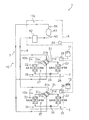
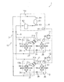
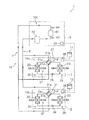
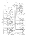
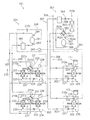
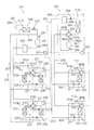
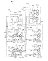
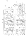
図1は、本発明にかかる第1実施形態の空気調和システム1の概略の冷媒回路図である。空気調和システム1は、蒸気圧縮式の冷凍サイクル運転を行うことによって、ビル等の屋内の潜熱負荷及び顕熱負荷を処理する空気調和システムである。空気調和システム1は、いわゆる、セパレート型のマルチ空気調和システムであり、主として、複数台(本実施形態では、2台)の利用ユニット2、3と、熱源ユニット6と、利用ユニット2、3と熱源ユニット6とを接続する連絡配管7、8とを備えている。本実施形態において、熱源ユニット6は、利用ユニット2、3に共通の熱源として機能する。また、本実施形態において、熱源ユニット6は、1台だけであるが、利用ユニット2、3の台数が多い場合等においては複数台を並列に接続していてもよい。
Hereinafter, an embodiment of an air conditioning system according to the present invention will be described based on the drawings.
[First Embodiment]
(1) Configuration of Air Conditioning System FIG. 1 is a schematic refrigerant circuit diagram of an air conditioning system 1 according to a first embodiment of the present invention. The air conditioning system 1 is an air conditioning system that processes an indoor latent heat load and a sensible heat load such as a building by performing a vapor compression refrigeration cycle operation. The air conditioning system 1 is a so-called separate type multi-air conditioning system, and mainly includes a plurality of (two in the present embodiment) usage units 2 and 3, a heat source unit 6, and usage units 2 and 3. Connecting pipes 7 and 8 for connecting the heat source unit 6 are provided. In the present embodiment, the heat source unit 6 functions as a heat source common to the utilization units 2 and 3. Further, in the present embodiment, only one heat source unit 6 is provided, but a plurality of units may be connected in parallel when the number of usage units 2 and 3 is large.

<利用ユニット>
利用ユニット2、3は、ビル等の屋内の天井に埋め込みや吊り下げ等により、壁掛け等により、又は、天井裏の空間に設置されている。利用ユニット2、3は、連絡配管7、8を介して熱源ユニット6に接続されており、熱源ユニット6との間で冷媒回路10を構成している。利用ユニット2、3は、この冷媒回路10内において冷媒を循環させて蒸気圧縮式の冷凍サイクル運転を行うことによって、屋内の潜熱負荷及び顕熱負荷を処理することが可能である。
<Usage unit>
The usage units 2 and 3 are installed in a ceiling or the like in a building or the like, embedded in a ceiling, or suspended from a wall, or in a space behind the ceiling. The utilization units 2 and 3 are connected to the heat source unit 6 via connection pipes 7 and 8, and constitute a refrigerant circuit 10 with the heat source unit 6. The utilization units 2 and 3 can process indoor latent heat load and sensible heat load by circulating a refrigerant in the refrigerant circuit 10 and performing a vapor compression refrigeration cycle operation.

次に、利用ユニット2、3の構成について説明する。尚、利用ユニット2と利用ユニット3とは同様の構成であるため、ここでは、利用ユニット2の構成のみ説明し、利用ユニット3の構成については、利用ユニット2の各部を示す20番台の符号の代わりに30番台の符号を付して、各部の説明を省略する。
利用ユニット2は、主として、冷媒回路10の一部を構成しており、空気を除湿又は加湿することが可能な利用側冷媒回路10aを備えている。この利用側冷媒回路10aは、主として、利用側四路切換弁21と、第1吸着熱交換器22と、第2吸着熱交換器23と、利用側膨張弁24とを備えている。
Next, the configuration of the usage units 2 and 3 will be described. Since the usage unit 2 and the usage unit 3 have the same configuration, only the configuration of the usage unit 2 will be described here. Instead, reference numerals in the 30s are attached, and descriptions of each part are omitted.
The usage unit 2 mainly constitutes a part of the refrigerant circuit 10 and includes a usage-side refrigerant circuit 10a that can dehumidify or humidify the air. The use side refrigerant circuit 10 a mainly includes a use side four-way switching valve 21, a first adsorption heat exchanger 22, a second adsorption heat exchanger 23, and a use side expansion valve 24.

利用側四路切換弁21は、利用側冷媒回路10aに流入する冷媒の流路を切り換えるための弁であり、その第1ポート21aは吐出ガス連絡配管7を介して熱源ユニット6の圧縮機構61(後述)の吐出側に接続されており、その第2ポート21bは吸入ガス連絡配管8を介して熱源ユニット6の圧縮機構61の吸入側に接続されており、その第3ポート21cは第1吸着熱交換器22のガス側端部に接続されており、第4ポート21dは第2吸着熱交換器23のガス側端部に接続されている。そして、利用側四路切換弁21は、第1ポート21aと第3ポート21cとを接続するとともに第2ポート21bと第4ポート21dとを接続(第1状態、図1の利用側四路切換弁21の実線を参照)したり、第1ポート21aと第4ポート21dとを接続するとともに第2ポート21bと第3ポート21cとを接続(第2状態、図1の利用側四路切換弁21の破線を参照)する切り換えを行うことが可能である。   The usage-side four-way switching valve 21 is a valve for switching the flow path of the refrigerant flowing into the usage-side refrigerant circuit 10 a, and the first port 21 a is a compression mechanism 61 of the heat source unit 6 via the discharge gas communication pipe 7. The second port 21b is connected to the suction side of the compression mechanism 61 of the heat source unit 6 via the suction gas communication pipe 8, and the third port 21c is the first port 21c. The fourth port 21 d is connected to the gas side end of the second adsorption heat exchanger 23, and is connected to the gas side end of the adsorption heat exchanger 22. The use-side four-way switching valve 21 connects the first port 21a and the third port 21c and connects the second port 21b and the fourth port 21d (first state, use-side four-way switching valve in FIG. 1). The first port 21a and the fourth port 21d are connected, and the second port 21b and the third port 21c are connected (second state, use side four-way switching valve in FIG. 1). It is possible to switch (see 21 dashed lines).

第1吸着熱交換器22及び第2吸着熱交換器23は、伝熱管と多数のフィンとにより構成されたクロスフィン式のフィン・アンド・チューブ型熱交換器である。具体的に、第1吸着熱交換器22及び第2吸着熱交換器23は、長方形板状に形成されたアルミニウム製の多数のフィンと、このフィンを貫通する銅製の伝熱管とを有している。尚、第1吸着熱交換器22及び第2吸着熱交換器23は、クロスフィン式のフィン・アンド・チューブ型熱交換器に限らず、他の形式の熱交換器、例えば、コルゲートフィン式の熱交換器等であってもよい。   The first adsorption heat exchanger 22 and the second adsorption heat exchanger 23 are cross fin type fin-and-tube heat exchangers configured by heat transfer tubes and a large number of fins. Specifically, the first adsorption heat exchanger 22 and the second adsorption heat exchanger 23 include a large number of aluminum fins formed in a rectangular plate shape, and a copper heat transfer tube penetrating the fins. Yes. The first adsorption heat exchanger 22 and the second adsorption heat exchanger 23 are not limited to cross-fin fin-and-tube heat exchangers, but other types of heat exchangers such as corrugated fin-type heat exchangers. It may be a heat exchanger or the like.

第1吸着熱交換器22及び第2吸着熱交換器23は、そのフィンの表面に吸着剤がディップ成形(浸漬成形)により担持されている。尚、フィン及び伝熱管の表面に吸着剤を担持させる方法としては、ディップ成形に限らず、吸着剤としての性能を損なわない限り、どのような方法でその表面に吸着剤を担持してもよい。この吸着剤としては、ゼオライト、シリカゲル、活性炭、親水性又は吸水性を有する有機高分子ポリマー系材料、カルボン酸基又はスルホン酸基を有するイオン交換樹脂系材料、感温性高分子等の機能性高分子材料などを用いることが可能である。   In the first adsorption heat exchanger 22 and the second adsorption heat exchanger 23, an adsorbent is supported on the surface of the fin by dip molding (immersion molding). The method for supporting the adsorbent on the surfaces of the fins and the heat transfer tubes is not limited to dip molding, and the adsorbent may be supported on the surface by any method as long as the performance as the adsorbent is not impaired. . As this adsorbent, functionalities such as zeolite, silica gel, activated carbon, organic polymer polymer material having hydrophilicity or water absorption, ion exchange resin material having carboxylic acid group or sulfonic acid group, temperature sensitive polymer, etc. A polymer material or the like can be used.

第1吸着熱交換器22及び第2吸着熱交換器23は、その外側に空気を通過させながら冷媒の蒸発器として機能させることで、その表面に担持された吸着剤に空気中の水分が吸着させることができる。また、第1吸着熱交換器22及び第2吸着熱交換器23は、その外側に空気を通過させながら冷媒の凝縮器として機能させることで、その表面に担持された吸着剤に吸着された水分を脱離させることができる。   The first adsorption heat exchanger 22 and the second adsorption heat exchanger 23 function as a refrigerant evaporator while allowing air to pass outside thereof, so that moisture in the air is adsorbed by the adsorbent supported on the surface of the first adsorption heat exchanger 22 and the second adsorption heat exchanger 23. Can be made. In addition, the first adsorption heat exchanger 22 and the second adsorption heat exchanger 23 function as a refrigerant condenser while allowing air to pass through the outside of the first adsorption heat exchanger 22 and the second adsorption heat exchanger 23. Can be desorbed.

利用側膨張弁24は、第1吸着熱交換器22の液側端部と第2吸着熱交換器23の液側端部との間に接続された電動膨張弁であり、凝縮器として機能する第1吸着熱交換器22及び第2吸着熱交換器23の一方から蒸発器として機能する第1吸着熱交換器22及び第2吸着熱交換器23の他方に送られる冷媒を減圧することができる。
また、利用ユニット2は、詳細は図示しないが、屋外の空気(以下、屋外空気OAとする)をユニット内に吸入するための外気吸入口と、ユニット内から屋外に空気を排出するための排気口と、屋内の空気(以下、屋内空気RAとする)をユニット内に吸入するための内気吸入口と、ユニット内から屋内に吹き出される空気(以下、供給空気SAとする)を供給するための給気口と、排気口に連通するようにユニット内に配置された排気ファンと、給気口に連通するようにユニット内に配置された給気ファンと、空気流路を切り換えるためのダンパー等からなる切換機構とを備えている。これにより、利用ユニット2は、屋外空気OAを外気吸入口からユニット内に吸入して第1又は第2吸着熱交換器22、23を通過させた後に給気口から屋内に供給空気SAとして供給したり、屋外空気OAを外気吸入口からユニット内に吸入して第1又は第2吸着熱交換器22、23を通過させた後に排気口から屋外に排出空気EAとして排出したり、屋内空気RAを内気吸入口からユニット内に吸入して第1又は第2吸着熱交換器22、23を通過させた後に給気口から屋内に供給空気SAとして供給したり、屋内空気RAを内気吸入口からユニット内に吸入して第1又は第2吸着熱交換器22、23を通過させた後に排気口から屋外に排出空気EAとして排出することができるようになっている。
The use side expansion valve 24 is an electric expansion valve connected between the liquid side end of the first adsorption heat exchanger 22 and the liquid side end of the second adsorption heat exchanger 23, and functions as a condenser. The refrigerant sent from one of the first adsorption heat exchanger 22 and the second adsorption heat exchanger 23 to the other of the first adsorption heat exchanger 22 and the second adsorption heat exchanger 23 functioning as an evaporator can be decompressed. .
Although not shown in detail, the utilization unit 2 has an outside air inlet for sucking outdoor air (hereinafter referred to as outdoor air OA) into the unit, and an exhaust for discharging air from inside the unit to the outdoors. To supply a mouth, an indoor air suction port for sucking indoor air (hereinafter referred to as indoor air RA) into the unit, and air (hereinafter referred to as supply air SA) blown into the unit from the inside of the unit Air supply port, an exhaust fan arranged in the unit so as to communicate with the exhaust port, an air supply fan arranged in the unit so as to communicate with the air supply port, and a damper for switching the air flow path And a switching mechanism made up of, and the like. As a result, the utilization unit 2 sucks the outdoor air OA from the outside air inlet into the unit, passes it through the first or second adsorption heat exchangers 22 and 23, and then supplies it as the supply air SA from the air inlet to the inside. Or after the outdoor air OA is sucked into the unit from the outside air inlet and passed through the first or second adsorption heat exchangers 22 and 23, it is discharged from the outlet to the outside as exhaust air EA, or the indoor air RA Is taken into the unit from the inside air inlet and passed through the first or second adsorption heat exchangers 22 and 23, and then supplied indoors as supply air SA from the air inlet, or indoor air RA is supplied from the inside air inlet. After being sucked into the unit and passed through the first or second adsorption heat exchangers 22 and 23, the air can be discharged from the exhaust port to the outside as exhaust air EA.

さらに、利用ユニット2は、ユニット内に吸入される屋内空気RAの温度及び相対湿度を検出するRA吸入温度・湿度センサ25と、ユニット内に吸入される屋外空気OAの温度及び相対湿度を検出するOA吸入温度・湿度センサ26と、ユニット内から屋内に供給される供給空気SAの温度を検出するSA供給温度センサ27と、利用ユニット2を構成する各部の動作を制御する利用側制御部28とを備えている。そして、利用側制御部28は、利用ユニット2の制御を行うために設けられたマイクロコンピュータやメモリを有しており、リモコン11及び後述の熱源ユニット6の熱源側制御部65を通じて、屋内の空気の目標温度及び目標湿度の入力信号等のやりとりを行ったり、熱源ユニット6との間で制御信号等のやりとりを行うこともできるようになっている。   Furthermore, the utilization unit 2 detects the temperature and relative humidity of the RA intake temperature / humidity sensor 25 that detects the temperature and relative humidity of the indoor air RA sucked into the unit, and the temperature and relative humidity of the outdoor air OA sucked into the unit. OA suction temperature / humidity sensor 26, SA supply temperature sensor 27 for detecting the temperature of supply air SA supplied indoors from within the unit, and use side control unit 28 for controlling the operation of each part constituting the use unit 2. It has. The use side control unit 28 includes a microcomputer and a memory provided for controlling the use unit 2, and the indoor air is supplied through the remote controller 11 and a heat source side control unit 65 of the heat source unit 6 described later. It is also possible to exchange input signals for the target temperature and target humidity, and to exchange control signals and the like with the heat source unit 6.

<熱源ユニット>
熱源ユニット6は、ビル等の屋上等に設置されており、連絡配管7、8を介して利用ユニット2、3に接続されており、利用ユニット2、3との間で冷媒回路10を構成している。
次に、熱源ユニット6の構成について説明する。熱源ユニット6は、主として、冷媒回路10の一部を構成しており、熱源側冷媒回路10cを備えている。この熱源側冷媒回路10cは、主として、圧縮機構61と、圧縮機構61の吸入側に接続されるアキュムレータ62とを備えている。
<Heat source unit>
The heat source unit 6 is installed on a rooftop of a building or the like, and is connected to the usage units 2 and 3 via connection pipes 7 and 8, and constitutes a refrigerant circuit 10 with the usage units 2 and 3. ing.
Next, the configuration of the heat source unit 6 will be described. The heat source unit 6 mainly constitutes a part of the refrigerant circuit 10 and includes a heat source side refrigerant circuit 10c. The heat source side refrigerant circuit 10 c mainly includes a compression mechanism 61 and an accumulator 62 connected to the suction side of the compression mechanism 61.

圧縮機構61は、本実施形態において、インバータ制御により運転容量を可変することが可能な容積式圧縮機である。本実施形態において、圧縮機構61は、1台の圧縮機であるが、これに限定されず、利用ユニットの接続台数等に応じて、2台以上の圧縮機が並列に接続されたものであってもよい。
アキュムレータ62は、利用側冷媒回路10a、10bの運転負荷の変動に伴う冷媒循環量の増減により発生する余剰冷媒を溜める容器である。
In the present embodiment, the compression mechanism 61 is a positive displacement compressor capable of varying the operation capacity by inverter control. In the present embodiment, the compression mechanism 61 is a single compressor, but is not limited to this, and two or more compressors are connected in parallel according to the number of units used and the like. May be.
The accumulator 62 is a container for accumulating surplus refrigerant generated by an increase or decrease in the amount of refrigerant circulation that accompanies fluctuations in the operating load of the usage-side refrigerant circuits 10a and 10b.

また、熱源ユニット6は、圧縮機構61の吸入圧力を検出する吸入圧力センサ63と、圧縮機構61の吐出圧力を検出する吐出圧力センサ64と、熱源ユニット6を構成する各部の動作を制御する熱源側制御部65とを備えている。そして、熱源側制御部65は、利用ユニット2の制御を行うために設けられたマイクロコンピュータやメモリを有しており、上述の利用ユニット2、3の利用側制御部28、38及び熱源側制御部65を通じて、制御信号等のやりとりを行うことができるようになっている。   The heat source unit 6 includes a suction pressure sensor 63 that detects the suction pressure of the compression mechanism 61, a discharge pressure sensor 64 that detects the discharge pressure of the compression mechanism 61, and a heat source that controls the operation of each part of the heat source unit 6. Side control unit 65. The heat source side control unit 65 includes a microcomputer and a memory provided to control the usage unit 2, and the usage side control units 28 and 38 of the above usage units 2 and 3 and the heat source side control. Through the unit 65, control signals and the like can be exchanged.

(2)空気調和システムの動作
次に、本実施形態の空気調和システム1の動作について説明する。空気調和システム1は、以下のような各種の除湿運転や加湿運転を行うことができる。
<全換気モード>
まず、全換気モードにおける除湿運転及び加湿運転について説明する。全換気モードにおいては、利用ユニット2、3の給気ファン及び排気ファンを運転すると、屋外空気OAが外気吸入口を通じてユニット内に吸入されて給気口を通じて供給空気SAとして屋内に供給され、屋内空気RAが内気吸入口を通じてユニット内に吸入されて排気口を通じて排出空気EAとして屋外に排出される運転が行われる。
(2) Operation | movement of an air conditioning system Next, operation | movement of the air conditioning system 1 of this embodiment is demonstrated. The air conditioning system 1 can perform the following various dehumidifying operations and humidifying operations.
<All ventilation modes>
First, the dehumidifying operation and the humidifying operation in the full ventilation mode will be described. In the full ventilation mode, when the air supply fan and the exhaust fan of the usage units 2 and 3 are operated, the outdoor air OA is drawn into the unit through the outside air inlet and supplied indoors as the supply air SA through the air inlet. An operation is performed in which the air RA is sucked into the unit through the inside air suction port and discharged to the outside as exhaust air EA through the exhaust port.

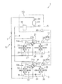
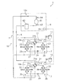
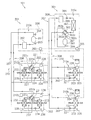
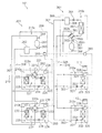
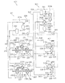
全換気モードの除湿運転中の動作について、図2、図3及び図4を用いて説明する。ここで、図2及び図3は、空気調和システム1における全換気モードの除湿運転時の動作を示す概略の冷媒回路図である。図4は、空気調和システム1を運転した場合における制御フロー図である。
除湿運転中には、図2及び図3に示されるように、例えば、利用ユニット2においては、第1吸着熱交換器22が凝縮器となって第2吸着熱交換器23が蒸発器となる第1動作と、第2吸着熱交換器23が凝縮器となって第1吸着熱交換器22が蒸発器となる第2動作とが交互に繰り返される。利用ユニット3においても同様に、第1吸着熱交換器32が凝縮器となって第2吸着熱交換器33が蒸発器となる第1動作と、第2吸着熱交換器33が凝縮器となって第1吸着熱交換器32が蒸発器となる第2動作とが交互に繰り返される。
The operation during the dehumidifying operation in the full ventilation mode will be described with reference to FIGS. 2, 3, and 4. Here, FIGS. 2 and 3 are schematic refrigerant circuit diagrams showing the operation during the dehumidifying operation in the total ventilation mode in the air conditioning system 1. FIG. 4 is a control flow diagram when the air conditioning system 1 is operated.
During the dehumidifying operation, as shown in FIGS. 2 and 3, for example, in the usage unit 2, the first adsorption heat exchanger 22 becomes a condenser and the second adsorption heat exchanger 23 becomes an evaporator. The first operation and the second operation in which the second adsorption heat exchanger 23 serves as a condenser and the first adsorption heat exchanger 22 serves as an evaporator are alternately repeated. Similarly, in the usage unit 3, the first adsorption heat exchanger 32 serves as a condenser and the second adsorption heat exchanger 33 serves as an evaporator, and the second adsorption heat exchanger 33 serves as a condenser. Thus, the second operation in which the first adsorption heat exchanger 32 becomes an evaporator is alternately repeated.

以下の説明では、2つの利用ユニット2、3の動作をまとめて記載する。
第1動作では、第1吸着熱交換器22、32についての再生動作と、第2吸着熱交換器23、33についての吸着動作とが並行して行われる。第1動作中は、図2に示されるように、利用側四路切換弁21、31が第1状態(図2の利用側四路切換弁21、31の実線を参照)に設定される。この状態で、圧縮機構61から吐出された高圧のガス冷媒は、吐出ガス連絡配管7、利用側四路切換弁21、31を通じて第1吸着熱交換器22、32に流入し、第1吸着熱交換器22、32を通過する間に凝縮する。そして、凝縮された冷媒は、利用側膨張弁24、34で減圧されて、その後、第2吸着熱交換器23、33を通過する間に蒸発し、利用側四路切換弁21、31、吸入ガス連絡配管8、アキュムレータ62を通じて圧縮機構61に再び吸入される(図2の冷媒回路10に付された矢印を参照)。
In the following description, the operations of the two usage units 2 and 3 will be described together.
In the first operation, the regeneration operation for the first adsorption heat exchangers 22 and 32 and the adsorption operation for the second adsorption heat exchangers 23 and 33 are performed in parallel. During the first operation, as shown in FIG. 2, the usage-side four-way switching valves 21 and 31 are set to the first state (see the solid lines of the usage-side four-way switching valves 21 and 31 in FIG. 2). In this state, the high-pressure gas refrigerant discharged from the compression mechanism 61 flows into the first adsorption heat exchangers 22 and 32 through the discharge gas communication pipe 7 and the use-side four-way switching valves 21 and 31, and the first adsorption heat. Condensation while passing through the exchangers 22, 32. The condensed refrigerant is depressurized by the use side expansion valves 24 and 34, and then evaporated while passing through the second adsorption heat exchangers 23 and 33, and the use side four-way switching valves 21 and 31 are sucked. The air is again sucked into the compression mechanism 61 through the gas communication pipe 8 and the accumulator 62 (see the arrow attached to the refrigerant circuit 10 in FIG. 2).

第1動作中において、第1吸着熱交換器22、32では、冷媒の凝縮により加熱された吸着剤から水分が脱離し、この脱離した水分が内気吸入口から吸入された屋内空気RAに付与される。第1吸着熱交換器22、32から脱離した水分は、屋内空気RAに同伴して排気口を通じて排出空気EAとして屋外へ排出される。第2吸着熱交換器23、33では、屋外空気OA中の水分が吸着剤に吸着されて屋外空気OAが除湿され、その際に生じた吸着熱が冷媒に吸熱されて冷媒が蒸発する。そして、第2吸着熱交換器23、33で除湿された屋外空気OAは、給気口を通って供給空気SAとして屋内へ供給される(図2の吸着熱交換器22、23、32、33の両側に付された矢印を参照)。   During the first operation, in the first adsorption heat exchangers 22 and 32, moisture is desorbed from the adsorbent heated by the condensation of the refrigerant, and the desorbed moisture is given to the indoor air RA sucked from the inside air intake port. Is done. The moisture desorbed from the first adsorption heat exchangers 22 and 32 is discharged to the outdoors as exhaust air EA through the exhaust port accompanying the indoor air RA. In the second adsorption heat exchangers 23 and 33, moisture in the outdoor air OA is adsorbed by the adsorbent and the outdoor air OA is dehumidified, and the adsorption heat generated at that time is absorbed by the refrigerant and the refrigerant evaporates. Then, the outdoor air OA dehumidified by the second adsorption heat exchangers 23 and 33 is supplied indoors as supply air SA through the air supply port (adsorption heat exchangers 22, 23, 32 and 33 in FIG. 2). (See arrows on both sides of the).

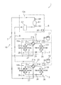
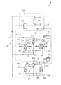
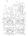
第2動作では、第1吸着熱交換器22、32についての吸着動作と、第2吸着熱交換器23、33についての再生動作とが並行して行われる。第2動作中は、図3に示されるように、利用側四路切換弁21、31が第2状態(図3の利用側四路切換弁21、31の破線を参照)に設定される。この状態で、圧縮機構61から吐出された高圧のガス冷媒は、吐出ガス連絡配管7、利用側四路切換弁21、31を通じて第2吸着熱交換器23、33に流入し、第2吸着熱交換器23、33を通過する間に凝縮する。そして、凝縮された冷媒は、利用側膨張弁24、34で減圧されて、その後、第1吸着熱交換器22、32を通過する間に蒸発し、利用側四路切換弁21、31、吸入ガス連絡配管8、アキュムレータ62を通じて圧縮機構61に再び吸入される(図3の冷媒回路10に付された矢印を参照)。   In the second operation, the adsorption operation for the first adsorption heat exchangers 22 and 32 and the regeneration operation for the second adsorption heat exchangers 23 and 33 are performed in parallel. During the second operation, as shown in FIG. 3, the usage-side four-way switching valves 21 and 31 are set to the second state (see the broken lines of the usage-side four-way switching valves 21 and 31 in FIG. 3). In this state, the high-pressure gas refrigerant discharged from the compression mechanism 61 flows into the second adsorption heat exchangers 23 and 33 through the discharge gas communication pipe 7 and the use-side four-way switching valves 21 and 31, and the second adsorption heat. Condensation while passing through exchangers 23, 33. The condensed refrigerant is depressurized by the use side expansion valves 24 and 34, and then evaporated while passing through the first adsorption heat exchangers 22 and 32, and the use side four-way switching valves 21 and 31 are sucked. The air is again sucked into the compression mechanism 61 through the gas communication pipe 8 and the accumulator 62 (see the arrow attached to the refrigerant circuit 10 in FIG. 3).

第2動作中において、第2吸着熱交換器23、33では、冷媒の凝縮により加熱された吸着剤から水分が脱離し、この脱離した水分が内気吸入口から吸入された屋内空気RAに付与される。第2吸着熱交換器23、33から脱離した水分は、屋内空気RAに同伴して排気口を通じて排出空気EAとして屋外へ排出される。第1吸着熱交換器22、32では、屋外空気OA中の水分が吸着剤に吸着されて屋外空気OAが除湿され、その際に生じた吸着熱が冷媒に吸熱されて冷媒が蒸発する。そして、第1吸着熱交換器22、32で除湿された屋外空気OAは、給気口を通って供給空気SAとして屋内へ供給される(図3の吸着熱交換器22、23、32、33の両側に付された矢印を参照)。   During the second operation, in the second adsorption heat exchangers 23 and 33, moisture is desorbed from the adsorbent heated by the condensation of the refrigerant, and the desorbed moisture is given to the indoor air RA sucked from the inside air intake port. Is done. The moisture desorbed from the second adsorption heat exchangers 23 and 33 is accompanied by the indoor air RA and discharged to the outdoors as exhaust air EA through the exhaust port. In the first adsorption heat exchangers 22 and 32, moisture in the outdoor air OA is adsorbed by the adsorbent and the outdoor air OA is dehumidified, and the adsorption heat generated at that time is absorbed by the refrigerant, and the refrigerant evaporates. The outdoor air OA dehumidified by the first adsorption heat exchangers 22 and 32 is supplied indoors as supply air SA through the air supply port (adsorption heat exchangers 22, 23, 32, and 33 in FIG. 3). (See arrows on both sides of the).

ここで、空気調和システム1において行われているシステム制御について説明する。
まず、リモコン11、12によって屋内の空気の目標温度及び目標相対湿度が設定されると、利用ユニット2、3の利用側制御部28、38には、これらの目標温度値及び目標相対湿度値とともに、RA吸入温度・湿度センサ25、35によって検出されたユニット内に吸入される屋内の空気の温度値及び相対湿度値と、OA吸入温度・湿度センサ26、36によって検出されたユニット内に吸入される屋外の空気の温度値及び相対湿度値とが入力される。
Here, the system control performed in the air conditioning system 1 will be described.
First, when the indoor air target temperature and target relative humidity are set by the remote controllers 11 and 12, the usage-side control units 28 and 38 of the usage units 2 and 3 have the target temperature value and the target relative humidity value. The temperature value and relative humidity value of indoor air sucked into the unit detected by the RA suction temperature / humidity sensors 25 and 35, and the air temperature sucked into the unit detected by the OA suction temperature / humidity sensors 26 and 36. The outdoor air temperature value and relative humidity value are input.

すると、ステップS1において、利用側制御部28、38は、屋内の空気の目標温度値及び目標相対湿度値からエンタルピの目標値又は絶対湿度の目標値を演算し、そして、RA吸入温度・湿度センサ25、35によって検出された温度値及び相対湿度値から屋内からユニット内に吸入される空気のエンタルピの現在値又は絶対湿度の現在値を演算し、両値の差(以下、必要潜熱能力値Δhとする)を演算する。ここで、必要潜熱能力値Δhは、上述のように屋内の空気のエンタルピの目標値又は絶対湿度の目標値と現在の屋内の空気のエンタルピ値又は絶対湿度値との差であるため、空気調和システム1において処理しなければならない潜熱負荷に相当するものである。そして、この必要潜熱能力値Δhの値を、利用ユニット2、3の処理能力を上げる必要があるかどうかを熱源側制御部65に知らせるための能力UP信号K1に変換する。例えば、Δhの絶対値が所定値よりも小さい場合(すなわち、屋内の空気の湿度値が目標湿度値に近い値であり、処理能力を増減する必要がない場合)には能力UP信号K1を「0」とし、Δhの絶対値が所定値よりも処理能力を上げなければならない方向に大きい場合(すなわち、除湿運転においては屋内の空気の湿度値が目標湿度値よりも高く、処理能力を上げる必要がある場合)には能力UP信号K1を「A」とし、Δhの絶対値が所定値よりも処理能力を下げなければならない方向に大きい場合(すなわち、除湿運転においては屋内の空気の湿度値が目標湿度値よりも低く、処理能力を下げる必要がある場合)には能力UP信号K1を「B」とする。   Then, in step S1, the use side control units 28 and 38 calculate the target value of enthalpy or the target value of absolute humidity from the target temperature value and target relative humidity value of indoor air, and the RA inhalation temperature / humidity sensor. The current value of the enthalpy of air sucked into the unit from the indoor or the current value of the absolute humidity is calculated from the temperature value and the relative humidity value detected by 25 and 35, and the difference between the two values (hereinafter referred to as the required latent heat capacity value Δh). )). Here, the necessary latent heat capacity value Δh is the difference between the target value of the indoor air enthalpy or the target value of absolute humidity and the current enthalpy value or absolute humidity value of the indoor air, as described above. This corresponds to the latent heat load that must be processed in the system 1. Then, the necessary latent heat capacity value Δh is converted into a capacity UP signal K1 for notifying the heat source side control section 65 whether or not the processing capacity of the utilization units 2 and 3 needs to be increased. For example, when the absolute value of Δh is smaller than a predetermined value (that is, when the humidity value of indoor air is close to the target humidity value and there is no need to increase or decrease the processing capacity), the capability UP signal K1 is set to “ 0, and when the absolute value of Δh is larger than the predetermined value in the direction in which the processing capacity must be increased (that is, in the dehumidifying operation, the humidity value of indoor air is higher than the target humidity value and the processing capacity needs to be increased) When the capacity UP signal K1 is “A” and the absolute value of Δh is larger than the predetermined value in the direction in which the processing capacity must be lowered (that is, in the dehumidifying operation, the humidity value of the indoor air is When the humidity is lower than the target humidity value and the processing capacity needs to be lowered, the capacity UP signal K1 is set to “B”.

次に、ステップS2において、熱源側制御部65は、利用側制御部28、38から伝送された利用ユニット2、3の能力UP信号K1を用いて、目標凝縮温度値TcS1及び目標蒸発温度値TeS1を演算する。例えば、目標凝縮温度値TcS1は、現在の目標凝縮温度値に利用ユニット2、3の能力UP信号K1を加算することによって演算される。また、目標蒸発温度値TeS1は、現在の目標蒸発温度値に利用ユニット2、3の能力UP信号K1を減算することによって演算される。これにより、能力UP信号K1の値が「A」の場合には、目標凝縮温度値TcS1は高くなり、目標蒸発温度値TeS1は低くなる。   Next, in step S2, the heat source side control unit 65 uses the capability UP signal K1 of the usage units 2 and 3 transmitted from the usage side control units 28 and 38, and uses the target condensation temperature value TcS1 and the target evaporation temperature value TeS1. Is calculated. For example, the target condensation temperature value TcS1 is calculated by adding the capability UP signal K1 of the usage units 2 and 3 to the current target condensation temperature value. Further, the target evaporation temperature value TeS1 is calculated by subtracting the capability UP signal K1 of the usage units 2 and 3 from the current target evaporation temperature value. Thereby, when the value of the capability UP signal K1 is “A”, the target condensing temperature value TcS1 becomes high and the target evaporation temperature value TeS1 becomes low.

次に、ステップS3において、空気調和システム1全体の凝縮温度及び蒸発温度の実測値に相当する値であるシステム凝縮温度値Tc1及びシステム蒸発温度値Te1を演算する。例えば、システム凝縮温度値Tc1及びシステム蒸発温度値Te1は、吸入圧力センサ63によって検出された圧縮機構61の吸入圧力値及び吐出圧力センサ64によって検出された圧縮機構61の吐出圧力値を、これらの圧力値における冷媒の飽和温度に換算することによって演算される。そして、システム凝縮温度値Tc1に対する目標凝縮温度値TcS1の温度差ΔTc1及びシステム蒸発温度値Te1に対する目標蒸発温度値TeS1の温度差ΔTe1を演算し、これらの温度差を除算することによって圧縮機構61の運転容量の増減の要否及び増減幅を決定する。   Next, in step S3, a system condensing temperature value Tc1 and a system evaporating temperature value Te1 which are values corresponding to actual measured values of the condensing temperature and the evaporating temperature of the entire air conditioning system 1 are calculated. For example, the system condensing temperature value Tc1 and the system evaporation temperature value Te1 are the suction pressure value of the compression mechanism 61 detected by the suction pressure sensor 63 and the discharge pressure value of the compression mechanism 61 detected by the discharge pressure sensor 64, respectively. It is calculated by converting into the refrigerant saturation temperature at the pressure value. Then, the temperature difference ΔTc1 of the target condensation temperature value TcS1 with respect to the system condensation temperature value Tc1 and the temperature difference ΔTe1 of the target evaporation temperature value TeS1 with respect to the system evaporation temperature value Te1 are calculated, and by dividing these temperature differences, the compression mechanism 61 Determine whether the operating capacity needs to be increased or decreased and the range of increase or decrease.

このようにして決定された圧縮機構61の運転容量を用いて、圧縮機構61の運転容量を制御することで、屋内の空気の目標温度及び目標相対湿度に近づけるシステム制御を行っている。例えば、温度差ΔTc1から温度差ΔTe1を差し引いた値が正値の場合には圧縮機構61の運転容量を増加させ、逆に、温度差ΔTc1から温度差ΔTe1を差し引いた値が負値の場合には圧縮機構61の運転容量を減少させるように制御する。   By controlling the operation capacity of the compression mechanism 61 using the operation capacity of the compression mechanism 61 determined in this way, system control is performed so as to approach the target temperature and target relative humidity of indoor air. For example, when the value obtained by subtracting the temperature difference ΔTe1 from the temperature difference ΔTc1 is a positive value, the operating capacity of the compression mechanism 61 is increased. Conversely, when the value obtained by subtracting the temperature difference ΔTe1 from the temperature difference ΔTc1 is a negative value Controls to reduce the operating capacity of the compression mechanism 61.

ここで、第1吸着熱交換器22、32及び第2吸着熱交換器23、33は、これらの吸着動作及び再生動作によって、空気中の水分を吸着したりや吸着された水分を空気中に脱離させる処理(以下、潜熱処理とする)だけでなく、通過する空気を冷却や加熱して温度を変化させる処理(以下、顕熱処理とする)も行っている。吸着熱交換器において得られる潜熱処理能力及び顕熱処理能力を第1動作及び第2動作、すなわち、吸着動作及び再生動作の切換時間間隔を横軸として表示したグラフを図5に示す。これによると、切換時間間隔を短くした場合(図5の時間C、潜熱優先モードとする)には潜熱処理、すなわち、空気中の水分を吸着したりや脱離させる処理が優先して行われるが、切換時間間隔を長くした場合(図5の時間D、顕熱優先モードとする)には顕熱処理、すなわち、空気を冷却や加熱して温度を変化させる処理が優先して行われることがわかる。例えば、蒸発器として機能する第1吸着熱交換器22、32及び第2吸着熱交換器23、33に空気を接触させると、最初は主として表面に設けられた吸着剤によって水分を吸着するため、この際に発生する吸着熱を処理することになるが、吸着剤の水分吸着容量近くまで水分を吸着してしまうと、その後は、主として空気を冷却することになるからである。また、凝縮器として機能する第1吸着熱交換器22、32及び第2吸着熱交換器23、33に空気を接触させると、最初は、主として表面に設けられた吸着剤の加熱処理により吸着剤に吸着された水分が空気中に脱離されることになるが、吸着剤に吸着された水分がほぼ脱離されてしまうと、その後は、主として空気を加熱することになるからである。そして、この切換時間間隔を利用側制御部28、38からの指令により変更することによって、潜熱処理能力に対する顕熱処理能力の割合(以下、顕熱処理能力比とする)を変更することができるようになっている。尚、後述のように、空気調和システム1は、通常運転時においては、主として潜熱処理を行うため、切換時間間隔を時間C、すなわち、潜熱優先モードに設定されている。   Here, the first adsorption heat exchangers 22 and 32 and the second adsorption heat exchangers 23 and 33 adsorb moisture in the air and desorb the adsorbed moisture into the air by the adsorption operation and the regeneration operation. In addition to the separation process (hereinafter referred to as latent heat treatment), a process of changing the temperature by cooling or heating the passing air (hereinafter referred to as sensible heat treatment) is also performed. FIG. 5 shows a graph in which the latent heat treatment capability and the sensible heat treatment capability obtained in the adsorption heat exchanger are displayed with the horizontal axis indicating the switching time interval between the first operation and the second operation, that is, the adsorption operation and the regeneration operation. According to this, when the switching time interval is shortened (time C in FIG. 5 is set to the latent heat priority mode), the latent heat treatment, that is, the process of adsorbing or desorbing moisture in the air is preferentially performed. When the switching time interval is lengthened (time D in FIG. 5, the sensible heat priority mode is set), it is understood that the sensible heat treatment, that is, the process of changing the temperature by cooling or heating the air is preferentially performed. . For example, when air is brought into contact with the first adsorption heat exchangers 22 and 32 and the second adsorption heat exchangers 23 and 33 functioning as an evaporator, moisture is first adsorbed mainly by an adsorbent provided on the surface. This is because the heat of adsorption generated at this time is processed, but if moisture is adsorbed to the vicinity of the moisture adsorption capacity of the adsorbent, air is mainly cooled thereafter. In addition, when air is brought into contact with the first adsorption heat exchangers 22 and 32 and the second adsorption heat exchangers 23 and 33 that function as condensers, the adsorbent is initially treated mainly by heat treatment of the adsorbent provided on the surface. This is because the moisture adsorbed on the air is desorbed in the air, but when the water adsorbed on the adsorbent is almost desorbed, the air is mainly heated thereafter. The ratio of the sensible heat treatment capacity to the latent heat treatment capacity (hereinafter referred to as the sensible heat treatment capacity ratio) can be changed by changing the switching time interval according to a command from the use side control units 28 and 38. It has become. As will be described later, since the air conditioning system 1 mainly performs the latent heat treatment during normal operation, the switching time interval is set to the time C, that is, the latent heat priority mode.

このように、この空気調和システム1では、全換気モードの除湿運転において、屋外の空気を除湿するとともに、切換時間間隔に応じて得られる顕熱処理能力によって冷却を行って屋内に供給する冷房運転を行うことができる。
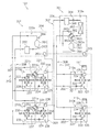
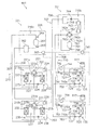
全換気モードの加湿運転中の動作について、図6及び図7を用いて説明する。ここで、図6及び図7は、空気調和システム1における全換気モードの加湿運転時の動作を示す概略の冷媒回路図である。尚、空気調和システム1において行われているシステム制御については、上述の全換気モードの除湿運転と同様であるため、説明を省略する。
As described above, in the air conditioning system 1, in the dehumidifying operation in the total ventilation mode, the outdoor air is dehumidified, and the cooling operation is performed by the sensible heat treatment capacity obtained according to the switching time interval and is supplied indoors. It can be carried out.
The operation during the humidifying operation in the full ventilation mode will be described with reference to FIGS. 6 and 7. Here, FIGS. 6 and 7 are schematic refrigerant circuit diagrams illustrating the operation during the humidifying operation in the total ventilation mode in the air conditioning system 1. In addition, about the system control currently performed in the air conditioning system 1, since it is the same as that of the above-mentioned dehumidification operation of all ventilation modes, description is abbreviate | omitted.

加湿運転中には、図6及び図7に示されるように、例えば、利用ユニット2においては、第1吸着熱交換器22が凝縮器となって第2吸着熱交換器23が蒸発器となる第1動作と、第2吸着熱交換器23が凝縮器となって第1吸着熱交換器22が蒸発器となる第2動作とが交互に繰り返される。利用ユニット3においても同様に、第1吸着熱交換器32が凝縮器となって第2吸着熱交換器33が蒸発器となる第1動作と、第2吸着熱交換器33が凝縮器となって第1吸着熱交換器32が蒸発器となる第2動作とが交互に繰り返される。以下、第1動作及び第2動作中における冷媒回路10内の冷媒の流れについては、上述の全換気モードの除湿運転と同様であるため、説明を省略し、第1動作及び第2動作中における空気の流れについてのみ説明する。   During the humidification operation, as shown in FIGS. 6 and 7, for example, in the utilization unit 2, the first adsorption heat exchanger 22 becomes a condenser and the second adsorption heat exchanger 23 becomes an evaporator. The first operation and the second operation in which the second adsorption heat exchanger 23 serves as a condenser and the first adsorption heat exchanger 22 serves as an evaporator are alternately repeated. Similarly, in the usage unit 3, the first adsorption heat exchanger 32 serves as a condenser and the second adsorption heat exchanger 33 serves as an evaporator, and the second adsorption heat exchanger 33 serves as a condenser. Thus, the second operation in which the first adsorption heat exchanger 32 is an evaporator is alternately repeated. Hereinafter, the flow of the refrigerant in the refrigerant circuit 10 during the first operation and the second operation is the same as the dehumidifying operation in the above-described all-ventilation mode, and thus the description thereof will be omitted, and during the first operation and the second operation. Only the air flow will be described.

第1動作中において、第1吸着熱交換器22、32では、冷媒の凝縮により加熱された吸着剤から水分が脱離し、この脱離した水分が外気吸入口から吸入された屋外空気OAに付与される。第1吸着熱交換器22、32から脱離した水分は、屋外空気OAに同伴して給気口を通じて供給空気SAとして屋内へ供給される。第2吸着熱交換器23、33では、屋内空気RA中の水分が吸着剤に吸着されて屋内空気RAが除湿され、その際に生じた吸着熱が冷媒に吸熱されて冷媒が蒸発する。そして、第2吸着熱交換器23、33で除湿された屋内空気RAは、排気口を通って排出空気EAとして屋外へ排出される(図6の吸着熱交換器22、23、32、33の両側に付された矢印を参照)。   During the first operation, in the first adsorption heat exchangers 22 and 32, moisture is desorbed from the adsorbent heated by the condensation of the refrigerant, and the desorbed moisture is given to the outdoor air OA sucked from the outside air inlet. Is done. The moisture desorbed from the first adsorption heat exchangers 22 and 32 is supplied indoors as the supply air SA through the air supply port along with the outdoor air OA. In the second adsorption heat exchangers 23 and 33, the moisture in the indoor air RA is adsorbed by the adsorbent to dehumidify the indoor air RA, and the heat of adsorption generated at that time is absorbed by the refrigerant and the refrigerant evaporates. Then, the indoor air RA dehumidified by the second adsorption heat exchangers 23 and 33 is discharged to the outside as exhaust air EA through the exhaust port (of the adsorption heat exchangers 22, 23, 32, and 33 in FIG. 6). (See arrows on both sides.)

第2動作中において、第2吸着熱交換器23、33では、冷媒の凝縮により加熱された吸着剤から水分が脱離し、この脱離した水分が外気吸入口から吸入された屋外空気OAに付与される。第2吸着熱交換器23、33から脱離した水分は、屋外空気OAに同伴して給気口を通じて供給空気SAとして屋内へ供給される。第1吸着熱交換器22、32では、屋内空気RA中の水分が吸着剤に吸着されて屋内空気RAが除湿され、その際に生じた吸着熱が冷媒に吸熱されて冷媒が蒸発する。そして、第1吸着熱交換器22、32で除湿された屋内空気RAは、排気口を通って排出空気EAとして屋外へ排出される(図7の吸着熱交換器22、23、32、33の両側に付された矢印を参照)。   During the second operation, in the second adsorption heat exchangers 23 and 33, moisture is desorbed from the adsorbent heated by the condensation of the refrigerant, and the desorbed moisture is given to the outdoor air OA sucked from the outside air inlet. Is done. The moisture desorbed from the second adsorption heat exchangers 23 and 33 is supplied indoors as the supply air SA through the air supply port along with the outdoor air OA. In the first adsorption heat exchangers 22 and 32, the moisture in the indoor air RA is adsorbed by the adsorbent to dehumidify the indoor air RA, and the heat of adsorption generated at that time is absorbed by the refrigerant and the refrigerant evaporates. Then, the indoor air RA dehumidified by the first adsorption heat exchangers 22 and 32 is discharged to the outside as exhaust air EA through the exhaust port (of the adsorption heat exchangers 22, 23, 32, and 33 in FIG. 7). See arrows on both sides).

ここで、第1吸着熱交換器22、32及び第2吸着熱交換器23、33は、上述の全換気モードの除湿運転と同様に、潜熱処理だけでなく、顕熱処理も行っている。
このように、この空気調和システム1では、全換気モードの加湿運転において、屋外の空気を加湿するとともに、切換時間間隔に応じて得られる顕熱処理能力によって加熱を行って屋内に供給する加湿運転を行うことができる。
Here, the first adsorption heat exchangers 22 and 32 and the second adsorption heat exchangers 23 and 33 perform not only the latent heat treatment but also the sensible heat treatment, as in the above-described dehumidifying operation in the full ventilation mode.
As described above, in the air conditioning system 1, in the humidification operation in the full ventilation mode, the outdoor air is humidified, and the humidification operation in which heating is performed by the sensible heat treatment ability obtained according to the switching time interval and the indoor air is supplied. It can be carried out.

<循環モード>
次に、循環モードにおける除湿運転及び加湿運転について説明する。循環モードにおいては、利用ユニット2、3の給気ファン及び排気ファンを運転すると、屋内空気RAが内気吸入口を通じてユニット内に吸入されて給気口を通じて供給空気SAとして屋内に供給され、屋外空気OAが外気吸入口を通じてユニット内に吸入されて排気口を通じて排出空気EAとして屋外に排出される運転が行われる。
<Circulation mode>
Next, the dehumidifying operation and the humidifying operation in the circulation mode will be described. In the circulation mode, when the air supply fan and the exhaust fan of the usage units 2 and 3 are operated, the indoor air RA is sucked into the unit through the inside air inlet and supplied indoors as the supply air SA through the air inlet, and the outdoor air An operation is performed in which OA is sucked into the unit through the outside air inlet and discharged to the outside as exhaust air EA through the outlet.

循環モードの除湿運転中の動作について、図8及び図9を用いて説明する。ここで、図8及び図9は、空気調和システム1における循環モードの除湿運転時の動作を示す概略の冷媒回路図である。尚、空気調和システム1において行われているシステム制御については、上述の全換気モードの除湿運転と同様であるため、説明を省略する。
除湿運転中には、図8及び図9に示されるように、例えば、利用ユニット2においては、第1吸着熱交換器22が凝縮器となって第2吸着熱交換器23が蒸発器となる第1動作と、第2吸着熱交換器23が凝縮器となって第1吸着熱交換器22が蒸発器となる第2動作とが交互に繰り返される。利用ユニット3においても同様に、第1吸着熱交換器32が凝縮器となって第2吸着熱交換器33が蒸発器となる第1動作と、第2吸着熱交換器33が凝縮器となって第1吸着熱交換器32が蒸発器となる第2動作とが交互に繰り返される。以下、第1動作及び第2動作中における冷媒回路10内の冷媒の流れについては、上述の全換気モードの除湿運転と同様であるため、説明を省略し、第1動作及び第2動作中における空気の流れについてのみ説明する。
The operation during the dehumidifying operation in the circulation mode will be described with reference to FIGS. Here, FIG. 8 and FIG. 9 are schematic refrigerant circuit diagrams showing the operation during the dehumidifying operation in the circulation mode in the air conditioning system 1. In addition, about the system control currently performed in the air conditioning system 1, since it is the same as that of the above-mentioned dehumidification operation of all ventilation modes, description is abbreviate | omitted.
During the dehumidifying operation, as shown in FIGS. 8 and 9, for example, in the usage unit 2, the first adsorption heat exchanger 22 becomes a condenser and the second adsorption heat exchanger 23 becomes an evaporator. The first operation and the second operation in which the second adsorption heat exchanger 23 serves as a condenser and the first adsorption heat exchanger 22 serves as an evaporator are alternately repeated. Similarly, in the usage unit 3, the first adsorption heat exchanger 32 serves as a condenser and the second adsorption heat exchanger 33 serves as an evaporator, and the second adsorption heat exchanger 33 serves as a condenser. Thus, the second operation in which the first adsorption heat exchanger 32 becomes an evaporator is alternately repeated. Hereinafter, the flow of the refrigerant in the refrigerant circuit 10 during the first operation and the second operation is the same as the above-described dehumidifying operation in the total ventilation mode, and thus the description thereof will be omitted, and during the first operation and the second operation. Only the flow of air will be described.

第1動作中において、第1吸着熱交換器22、32では、冷媒の凝縮により加熱された吸着剤から水分が脱離し、この脱離した水分が外気吸入口から吸入された屋外空気OAに付与される。第1吸着熱交換器22、32から脱離した水分は、屋外空気OAに同伴して排気口を通じて排出空気EAとして屋外へ排出される。第2吸着熱交換器23、33では、屋内空気RA中の水分が吸着剤に吸着されて屋内空気RAが除湿され、その際に生じた吸着熱が冷媒に吸熱されて冷媒が蒸発する。そして、第2吸着熱交換器23、33で除湿された屋内空気RAは、給気口を通って供給空気SAとして屋内へ供給される(図8の吸着熱交換器22、23、32、33の両側に付された矢印を参照)。   During the first operation, in the first adsorption heat exchangers 22 and 32, moisture is desorbed from the adsorbent heated by the condensation of the refrigerant, and the desorbed moisture is given to the outdoor air OA sucked from the outside air inlet. Is done. The moisture desorbed from the first adsorption heat exchangers 22 and 32 is discharged to the outdoors as exhaust air EA through the exhaust port accompanying the outdoor air OA. In the second adsorption heat exchangers 23 and 33, the moisture in the indoor air RA is adsorbed by the adsorbent to dehumidify the indoor air RA, and the heat of adsorption generated at that time is absorbed by the refrigerant and the refrigerant evaporates. Then, the indoor air RA dehumidified by the second adsorption heat exchangers 23 and 33 is supplied indoors as supply air SA through the air supply port (adsorption heat exchangers 22, 23, 32, and 33 in FIG. 8). (See arrows on both sides of the).

第2動作中において、第2吸着熱交換器23、33では、冷媒の凝縮により加熱された吸着剤から水分が脱離し、この脱離した水分が外気吸入口から吸入された屋外空気OAに付与される。第2吸着熱交換器23、33から脱離した水分は、屋外空気OAに同伴して排気口を通じて排出空気EAとして屋外へ排出される。第1吸着熱交換器22、32では、屋内空気RA中の水分が吸着剤に吸着されて屋内の空気が除湿され、その際に生じた吸着熱が冷媒に吸熱されて冷媒が蒸発する。そして、第1吸着熱交換器22、32で除湿された屋内空気RAは、給気口を通って供給空気SAとして屋内へ供給される(図9の吸着熱交換器22、23、32、33の両側に付された矢印を参照)。   During the second operation, in the second adsorption heat exchangers 23 and 33, moisture is desorbed from the adsorbent heated by the condensation of the refrigerant, and the desorbed moisture is given to the outdoor air OA sucked from the outside air inlet. Is done. The moisture desorbed from the second adsorption heat exchangers 23 and 33 is accompanied by the outdoor air OA and discharged to the outdoors as exhaust air EA through the exhaust port. In the first adsorption heat exchangers 22 and 32, the moisture in the indoor air RA is adsorbed by the adsorbent and the indoor air is dehumidified, and the adsorption heat generated at that time is absorbed by the refrigerant and the refrigerant evaporates. And the indoor air RA dehumidified by the 1st adsorption heat exchangers 22 and 32 is supplied indoors as supply air SA through an air supply opening (Adsorption heat exchangers 22, 23, 32, and 33 of FIG. 9). (See arrows on both sides of the).

ここで、第1吸着熱交換器22、32及び第2吸着熱交換器23、33は、潜熱処理だけでなく、顕熱処理も行っている。
このように、この空気調和システム1では、循環モードの除湿運転において、屋内の空気を除湿するとともに、切換時間間隔に応じて得られる顕熱処理能力によって冷却を行って屋内に供給する除湿運転を行うことができる。
Here, the first adsorption heat exchangers 22 and 32 and the second adsorption heat exchangers 23 and 33 perform not only latent heat treatment but also sensible heat treatment.
As described above, in the air conditioning system 1, in the dehumidifying operation in the circulation mode, the indoor air is dehumidified, and the dehumidifying operation in which cooling is performed by the sensible heat treatment capability obtained according to the switching time interval and the indoor air is supplied. be able to.

循環モードの加湿運転中の動作について、図10及び図11を用いて説明する。ここで、図10及び図11は、空気調和システム1における循環モードの除湿運転時の動作を示す概略の冷媒回路図である。尚、空気調和システム1において行われているシステム制御については、上述の全換気モードの除湿運転と同様であるため、説明を省略する。
加湿運転中には、図10及び図11に示されるように、例えば、利用ユニット2においては、第1吸着熱交換器22が凝縮器となって第2吸着熱交換器23が蒸発器となる第1動作と、第2吸着熱交換器23が凝縮器となって第1吸着熱交換器22が蒸発器となる第2動作とが交互に繰り返される。利用ユニット3においても同様に、第1吸着熱交換器32が凝縮器となって第2吸着熱交換器33が蒸発器となる第1動作と、第2吸着熱交換器33が凝縮器となって第1吸着熱交換器32が蒸発器となる第2動作とが交互に繰り返される。以下、第1動作及び第2動作中における冷媒回路10内の冷媒の流れについては、上述の全換気モードの除湿運転と同様であるため、説明を省略し、第1動作及び第2動作中における空気の流れについてのみ説明する。
The operation during the humidification operation in the circulation mode will be described with reference to FIGS. Here, FIG. 10 and FIG. 11 are schematic refrigerant circuit diagrams showing the operation during the dehumidifying operation in the circulation mode in the air conditioning system 1. In addition, about the system control currently performed in the air conditioning system 1, since it is the same as that of the above-mentioned dehumidification operation of all ventilation modes, description is abbreviate | omitted.
During the humidification operation, as shown in FIGS. 10 and 11, for example, in the usage unit 2, the first adsorption heat exchanger 22 becomes a condenser and the second adsorption heat exchanger 23 becomes an evaporator. The first operation and the second operation in which the second adsorption heat exchanger 23 serves as a condenser and the first adsorption heat exchanger 22 serves as an evaporator are alternately repeated. Similarly, in the usage unit 3, the first adsorption heat exchanger 32 serves as a condenser and the second adsorption heat exchanger 33 serves as an evaporator, and the second adsorption heat exchanger 33 serves as a condenser. Thus, the second operation in which the first adsorption heat exchanger 32 becomes an evaporator is alternately repeated. Hereinafter, the flow of the refrigerant in the refrigerant circuit 10 during the first operation and the second operation is the same as the above-described dehumidifying operation in the total ventilation mode, and thus the description thereof will be omitted, and during the first operation and the second operation. Only the flow of air will be described.

第1動作中において、第1吸着熱交換器22、32では、冷媒の凝縮により加熱された吸着剤から水分が脱離し、この脱離した水分が内気吸入口から吸入された屋内空気RAに付与される。第1吸着熱交換器22、32から脱離した水分は、屋内空気RAに同伴して給気口を通じて供給空気SAとして屋内へ供給される。第2吸着熱交換器23、33では、屋外空気OA中の水分が吸着剤に吸着されて屋外空気OAが除湿され、その際に生じた吸着熱が冷媒に吸熱されて冷媒が蒸発する。そして、第2吸着熱交換器23、33で除湿された屋外空気OAは、排気口を通って排出空気EAとして屋外へ排出される(図10の吸着熱交換器22、23、32、33の両側に付された矢印を参照)。   During the first operation, in the first adsorption heat exchangers 22 and 32, moisture is desorbed from the adsorbent heated by the condensation of the refrigerant, and the desorbed moisture is given to the indoor air RA sucked from the inside air intake port. Is done. The moisture desorbed from the first adsorption heat exchangers 22 and 32 is supplied indoors as the supply air SA through the air supply port along with the indoor air RA. In the second adsorption heat exchangers 23 and 33, moisture in the outdoor air OA is adsorbed by the adsorbent and the outdoor air OA is dehumidified, and the adsorption heat generated at that time is absorbed by the refrigerant and the refrigerant evaporates. Then, the outdoor air OA dehumidified by the second adsorption heat exchangers 23 and 33 is discharged outdoors as exhaust air EA through the exhaust port (of the adsorption heat exchangers 22, 23, 32, and 33 in FIG. 10). (See arrows on both sides.)

第2動作中において、第2吸着熱交換器23、33では、冷媒の凝縮により加熱された吸着剤から水分が脱離し、この脱離した水分が内気吸入口から吸入された屋内空気RAに付与される。第2吸着熱交換器23、33から脱離した水分は、屋内空気RAに同伴して給気口を通じて供給空気SAとして屋内へ供給される。第1吸着熱交換器22、32では、屋外空気OA中の水分が吸着剤に吸着されて屋外空気OAが除湿され、その際に生じた吸着熱が冷媒に吸熱されて冷媒が蒸発する。そして、第1吸着熱交換器22、32で除湿された屋外空気OAは、排気口を通って排出空気EAとして屋外へ排出される(図11の吸着熱交換器22、23、32、33の両側に付された矢印を参照)。   During the second operation, in the second adsorption heat exchangers 23 and 33, moisture is desorbed from the adsorbent heated by the condensation of the refrigerant, and the desorbed moisture is given to the indoor air RA sucked from the inside air intake port. Is done. The moisture desorbed from the second adsorption heat exchangers 23 and 33 is supplied indoors as the supply air SA through the air supply port along with the indoor air RA. In the first adsorption heat exchangers 22 and 32, moisture in the outdoor air OA is adsorbed by the adsorbent and the outdoor air OA is dehumidified, and the adsorption heat generated at that time is absorbed by the refrigerant, and the refrigerant evaporates. And the outdoor air OA dehumidified by the 1st adsorption heat exchangers 22 and 32 is discharged | emitted outdoors as exhaust air EA through an exhaust port (of the adsorption heat exchangers 22, 23, 32, and 33 of FIG. 11). (See arrows on both sides.)

ここで、第1吸着熱交換器22、32及び第2吸着熱交換器23、33は、上述の全換気モードの除湿運転と同様に、潜熱処理だけでなく、顕熱処理も行っている。
このように、この空気調和システム1では、循環モードの加湿運転において、屋内の空気を加湿するとともに、切換時間間隔に応じて得られる顕熱処理能力によって加熱を行って屋内に供給する加湿暖房運転を行うことができる。
Here, the first adsorption heat exchangers 22 and 32 and the second adsorption heat exchangers 23 and 33 perform not only the latent heat treatment but also the sensible heat treatment, as in the above-described dehumidifying operation in the full ventilation mode.
As described above, in the air conditioning system 1, in the humidification operation in the circulation mode, the indoor air is humidified, and the humidification heating operation in which the heating is performed by the sensible heat treatment capability obtained according to the switching time interval and the indoor air is supplied. It can be carried out.

<給気モード>
次に、給気モードにおける除湿運転及び加湿運転について説明する。給気モードにおいては、利用ユニット2、3の給気ファン及び排気ファンを運転すると、屋外空気OAが外気吸入口を通じてユニット内に吸入されて給気口を通じて供給空気SAとして屋内に供給され、屋外空気OAが外気吸入口を通じてユニット内に吸入されて排気口を通じて排出空気EAとして屋外に排出される運転が行われる。
<Air supply mode>
Next, the dehumidifying operation and the humidifying operation in the air supply mode will be described. In the air supply mode, when the air supply fan and the exhaust fan of the usage units 2 and 3 are operated, the outdoor air OA is sucked into the unit through the outside air inlet and supplied indoors as the supply air SA through the air inlet. An operation is performed in which the air OA is sucked into the unit through the outside air inlet and discharged to the outside as exhaust air EA through the exhaust port.

給気モードの除湿運転中の動作について、図12及び図13を用いて説明する。ここで、図12及び図13は、空気調和システム1における給気モードの除湿運転時の動作を示す概略の冷媒回路図である。尚、空気調和システム1において行われているシステム制御については、上述の全換気モードの除湿運転と同様であるため、説明を省略する。
除湿運転中には、図12及び図13に示されるように、例えば、利用ユニット2においては、第1吸着熱交換器22が凝縮器となって第2吸着熱交換器23が蒸発器となる第1動作と、第2吸着熱交換器23が凝縮器となって第1吸着熱交換器22が蒸発器となる第2動作とが交互に繰り返される。利用ユニット3においても同様に、第1吸着熱交換器32が凝縮器となって第2吸着熱交換器33が蒸発器となる第1動作と、第2吸着熱交換器33が凝縮器となって第1吸着熱交換器32が蒸発器となる第2動作とが交互に繰り返される。以下、第1動作及び第2動作中における冷媒回路10内の冷媒の流れについては、上述の全換気モードの除湿運転と同様であるため、説明を省略し、第1動作及び第2動作中における空気の流れについてのみ説明する。
The operation during the dehumidifying operation in the air supply mode will be described with reference to FIGS. Here, FIG. 12 and FIG. 13 are schematic refrigerant circuit diagrams showing the operation during the dehumidifying operation in the air supply mode in the air conditioning system 1. In addition, about the system control currently performed in the air conditioning system 1, since it is the same as that of the above-mentioned dehumidification operation of all ventilation modes, description is abbreviate | omitted.
During the dehumidifying operation, as shown in FIGS. 12 and 13, for example, in the usage unit 2, the first adsorption heat exchanger 22 becomes a condenser and the second adsorption heat exchanger 23 becomes an evaporator. The first operation and the second operation in which the second adsorption heat exchanger 23 serves as a condenser and the first adsorption heat exchanger 22 serves as an evaporator are alternately repeated. Similarly, in the usage unit 3, the first adsorption heat exchanger 32 serves as a condenser and the second adsorption heat exchanger 33 serves as an evaporator, and the second adsorption heat exchanger 33 serves as a condenser. Thus, the second operation in which the first adsorption heat exchanger 32 becomes an evaporator is alternately repeated. Hereinafter, the flow of the refrigerant in the refrigerant circuit 10 during the first operation and the second operation is the same as the above-described dehumidifying operation in the total ventilation mode, and thus the description thereof will be omitted, and during the first operation and the second operation. Only the flow of air will be described.

第1動作中において、第1吸着熱交換器22、32では、冷媒の凝縮により加熱された吸着剤から水分が脱離し、この脱離した水分が外気吸入口から吸入された屋外空気OAに付与される。第1吸着熱交換器22、32から脱離した水分は、屋外空気OAに同伴して排気口を通じて排出空気EAとして屋外へ排出される。第2吸着熱交換器23、33では、屋外空気OA中の水分が吸着剤に吸着されて屋外空気OAが除湿され、その際に生じた吸着熱が冷媒に吸熱されて冷媒が蒸発する。そして、第2吸着熱交換器23、33で除湿された屋外空気OAは、給気口を通って供給空気SAとして屋内へ供給される(図12の吸着熱交換器22、23、32、33の両側に付された矢印を参照)。   During the first operation, in the first adsorption heat exchangers 22 and 32, moisture is desorbed from the adsorbent heated by the condensation of the refrigerant, and the desorbed moisture is given to the outdoor air OA sucked from the outside air inlet. Is done. The moisture desorbed from the first adsorption heat exchangers 22 and 32 is discharged to the outdoors as exhaust air EA through the exhaust port accompanying the outdoor air OA. In the second adsorption heat exchangers 23 and 33, moisture in the outdoor air OA is adsorbed by the adsorbent and the outdoor air OA is dehumidified, and the adsorption heat generated at that time is absorbed by the refrigerant and the refrigerant evaporates. The outdoor air OA dehumidified by the second adsorption heat exchangers 23 and 33 is supplied indoors as supply air SA through the air supply port (adsorption heat exchangers 22, 23, 32, and 33 in FIG. 12). (See arrows on both sides of the).

第2動作中において、第2吸着熱交換器23、33では、冷媒の凝縮により加熱された吸着剤から水分が脱離し、この脱離した水分が外気吸入口から吸入された屋外空気OAに付与される。第2吸着熱交換器23、33から脱離した水分は、屋外空気OAに同伴して排気口を通じて排出空気EAとして屋外に排出される。第1吸着熱交換器22、32では、屋外空気OA中の水分が吸着剤に吸着されて屋外空気OAが除湿され、その際に生じた吸着熱が冷媒に吸熱されて冷媒が蒸発する。そして、第1吸着熱交換器22、32で除湿された屋外空気OAは、給気口を通って供給空気SAとして屋内へ供給される(図13の吸着熱交換器22、23、32、33の両側に付された矢印を参照)。   During the second operation, in the second adsorption heat exchangers 23 and 33, moisture is desorbed from the adsorbent heated by the condensation of the refrigerant, and the desorbed moisture is given to the outdoor air OA sucked from the outside air inlet. Is done. The moisture desorbed from the second adsorption heat exchangers 23 and 33 is accompanied by the outdoor air OA and discharged to the outdoors as exhaust air EA through the exhaust port. In the first adsorption heat exchangers 22 and 32, moisture in the outdoor air OA is adsorbed by the adsorbent and the outdoor air OA is dehumidified, and the adsorption heat generated at that time is absorbed by the refrigerant, and the refrigerant evaporates. And the outdoor air OA dehumidified by the 1st adsorption heat exchangers 22 and 32 is supplied indoors as supply air SA through an air supply port (Adsorption heat exchangers 22, 23, 32, and 33 of FIG. 13). (See arrows on both sides of the).

ここで、第1吸着熱交換器22、32及び第2吸着熱交換器23、33は、潜熱処理だけでなく、顕熱処理も行っている。
このように、この空気調和システム1では、給気モードの除湿運転において、屋外の空気を除湿するとともに、切換時間間隔に応じて得られる顕熱処理能力によって冷却を行って屋内に供給する除湿運転を行うことができる。
Here, the first adsorption heat exchangers 22 and 32 and the second adsorption heat exchangers 23 and 33 perform not only latent heat treatment but also sensible heat treatment.
As described above, in the air conditioning system 1, in the dehumidifying operation in the air supply mode, the outdoor air is dehumidified, and the dehumidifying operation in which cooling is performed by the sensible heat treatment ability obtained according to the switching time interval and the indoor air is supplied. It can be carried out.

給気モードの加湿運転中の動作について、図14及び図15を用いて説明する。ここで、図14及び図15は、空気調和システム1における給気モードの加湿運転時の動作を示す概略の冷媒回路図である。尚、空気調和システム1において行われているシステム制御については、上述の全換気モードの除湿運転と同様であるため、説明を省略する。
加湿運転中には、図14及び図15に示されるように、例えば、利用ユニット2においては、第1吸着熱交換器22が凝縮器となって第2吸着熱交換器23が蒸発器となる第1動作と、第2吸着熱交換器23が凝縮器となって第1吸着熱交換器22が蒸発器となる第2動作とが交互に繰り返される。利用ユニット3においても同様に、第1吸着熱交換器32が凝縮器となって第2吸着熱交換器33が蒸発器となる第1動作と、第2吸着熱交換器33が凝縮器となって第1吸着熱交換器32が蒸発器となる第2動作とが交互に繰り返される。以下、第1動作及び第2動作中における冷媒回路10内の冷媒の流れについては、上述の全換気モードの除湿運転と同様であるため、説明を省略し、第1動作及び第2動作中における空気の流れについてのみ説明する。
The operation during the humidifying operation in the air supply mode will be described with reference to FIGS. 14 and 15. Here, FIG. 14 and FIG. 15 are schematic refrigerant circuit diagrams showing the operation during the humidifying operation in the air supply mode in the air conditioning system 1. In addition, about the system control currently performed in the air conditioning system 1, since it is the same as that of the above-mentioned dehumidification operation of all ventilation modes, description is abbreviate | omitted.
14 and 15, during the humidification operation, for example, in the usage unit 2, the first adsorption heat exchanger 22 becomes a condenser and the second adsorption heat exchanger 23 becomes an evaporator. The first operation and the second operation in which the second adsorption heat exchanger 23 serves as a condenser and the first adsorption heat exchanger 22 serves as an evaporator are alternately repeated. Similarly, in the usage unit 3, the first adsorption heat exchanger 32 serves as a condenser and the second adsorption heat exchanger 33 serves as an evaporator, and the second adsorption heat exchanger 33 serves as a condenser. Thus, the second operation in which the first adsorption heat exchanger 32 becomes an evaporator is alternately repeated. Hereinafter, the flow of the refrigerant in the refrigerant circuit 10 during the first operation and the second operation is the same as the above-described dehumidifying operation in the total ventilation mode, and thus the description thereof will be omitted, and during the first operation and the second operation. Only the flow of air will be described.

第1動作中において、第1吸着熱交換器22、32では、冷媒の凝縮により加熱された吸着剤から水分が脱離し、この脱離した水分が外気吸入口から吸入された屋外空気OAに付与される。第1吸着熱交換器22、32から脱離した水分は、屋外空気OAに同伴して給気口を通じて供給空気SAとして屋内へ供給される。第2吸着熱交換器23、33では、屋外空気OA中の水分が吸着剤に吸着されて屋外の空気が除湿され、その際に生じた吸着熱が冷媒に吸熱されて冷媒が蒸発する。そして、第2吸着熱交換器23、33で除湿された屋外空気OAは、排気口を通って排出空気EAとして屋外へ排出される(図14の吸着熱交換器22、23、32、33の両側に付された矢印を参照)。   During the first operation, in the first adsorption heat exchangers 22 and 32, moisture is desorbed from the adsorbent heated by the condensation of the refrigerant, and the desorbed moisture is given to the outdoor air OA sucked from the outside air inlet. Is done. The moisture desorbed from the first adsorption heat exchangers 22 and 32 is supplied indoors as the supply air SA through the air supply port along with the outdoor air OA. In the second adsorption heat exchangers 23 and 33, the moisture in the outdoor air OA is adsorbed by the adsorbent and the outdoor air is dehumidified, and the adsorption heat generated at that time is absorbed by the refrigerant and the refrigerant evaporates. Then, the outdoor air OA dehumidified by the second adsorption heat exchangers 23 and 33 is discharged outdoors as exhaust air EA through the exhaust port (of the adsorption heat exchangers 22, 23, 32, and 33 in FIG. 14). (See arrows on both sides.)

第2動作中において、第2吸着熱交換器23、33では、冷媒の凝縮により加熱された吸着剤から水分が脱離し、この脱離した水分が外気吸入口から吸入された屋外空気OAに付与される。第2吸着熱交換器23、33から脱離した水分は、屋外空気OAに同伴して給気口を通じて供給空気SAとして屋内へ供給される。第1吸着熱交換器22、32では、屋外空気OA中の水分が吸着剤に吸着されて屋外空気OAが除湿され、その際に生じた吸着熱が冷媒に吸熱されて冷媒が蒸発する。そして、第1吸着熱交換器22、32で除湿された屋外空気OAは、排気口を通って排出空気EAとして屋外へ排出される(図15の吸着熱交換器22、23、32、33の両側に付された矢印を参照)。   During the second operation, in the second adsorption heat exchangers 23 and 33, moisture is desorbed from the adsorbent heated by the condensation of the refrigerant, and the desorbed moisture is given to the outdoor air OA sucked from the outside air inlet. Is done. The moisture desorbed from the second adsorption heat exchangers 23 and 33 is supplied indoors as the supply air SA through the air supply port along with the outdoor air OA. In the first adsorption heat exchangers 22 and 32, moisture in the outdoor air OA is adsorbed by the adsorbent and the outdoor air OA is dehumidified, and the adsorption heat generated at that time is absorbed by the refrigerant, and the refrigerant evaporates. Then, the outdoor air OA dehumidified by the first adsorption heat exchangers 22 and 32 is discharged to the outdoors as exhaust air EA through the exhaust port (of the adsorption heat exchangers 22, 23, 32, and 33 in FIG. 15). (See arrows on both sides.)

ここで、第1吸着熱交換器22、32及び第2吸着熱交換器23、33は、潜熱処理だけでなく、顕熱処理も行っている。
このように、この空気調和システム1では、給気モードの加湿運転において、屋外の空気を加湿するとともに、切換時間間隔に応じて得られる顕熱処理能力によって加熱を行って屋内に供給する加湿運転を行うことができる。
Here, the first adsorption heat exchangers 22 and 32 and the second adsorption heat exchangers 23 and 33 perform not only latent heat treatment but also sensible heat treatment.
Thus, in this air conditioning system 1, in the humidification operation in the air supply mode, the outdoor air is humidified, and the humidification operation in which heating is performed by the sensible heat treatment capability obtained according to the switching time interval and the indoor air is supplied. It can be carried out.

<排気モード>
次に、排気モードにおける除湿運転及び加湿運転について説明する。排気モードにおいては、利用ユニット2、3の給気ファン及び排気ファンを運転すると、屋内空気RAが内気吸入口を通じてユニット内に吸入されて給気口を通じて供給空気SAとして屋内に供給され、屋内空気RAが内気吸入口を通じてユニット内に吸入されて排気口を通じて排出空気EAとして屋外に排出される運転が行われる。
<Exhaust mode>
Next, the dehumidifying operation and the humidifying operation in the exhaust mode will be described. In the exhaust mode, when the air supply fan and the exhaust fan of the usage units 2 and 3 are operated, the indoor air RA is sucked into the unit through the indoor air inlet and supplied indoors as the supply air SA through the air inlet. An operation is performed in which RA is sucked into the unit through the inside air inlet and discharged to the outside as exhaust air EA through the outlet.

排気モードの除湿運転中の動作について、図16及び図17を用いて説明する。ここで、図16及び図17は、空気調和システム1における排気モードの除湿運転時の動作を示す概略の冷媒回路図である。尚、空気調和システム1において行われているシステム制御については、上述の全換気モードの除湿運転と同様であるため、説明を省略する。
除湿運転中には、図16及び図17に示されるように、例えば、利用ユニット2においては、第1吸着熱交換器22が凝縮器となって第2吸着熱交換器23が蒸発器となる第1動作と、第2吸着熱交換器23が凝縮器となって第1吸着熱交換器22が蒸発器となる第2動作とが交互に繰り返される。利用ユニット3においても同様に、第1吸着熱交換器32が凝縮器となって第2吸着熱交換器33が蒸発器となる第1動作と、第2吸着熱交換器33が凝縮器となって第1吸着熱交換器32が蒸発器となる第2動作とが交互に繰り返される。以下、第1動作及び第2動作中における冷媒回路10内の冷媒の流れについては、上述の全換気モードの除湿運転と同様であるため、説明を省略し、第1動作及び第2動作中における空気の流れについてのみ説明する。
The operation during the dehumidifying operation in the exhaust mode will be described with reference to FIGS. 16 and 17. Here, FIGS. 16 and 17 are schematic refrigerant circuit diagrams showing the operation during the dehumidifying operation in the exhaust mode in the air conditioning system 1. In addition, about the system control currently performed in the air conditioning system 1, since it is the same as that of the above-mentioned dehumidification operation of all ventilation modes, description is abbreviate | omitted.
During the dehumidifying operation, as shown in FIGS. 16 and 17, for example, in the utilization unit 2, the first adsorption heat exchanger 22 serves as a condenser and the second adsorption heat exchanger 23 serves as an evaporator. The first operation and the second operation in which the second adsorption heat exchanger 23 serves as a condenser and the first adsorption heat exchanger 22 serves as an evaporator are alternately repeated. Similarly, in the usage unit 3, the first adsorption heat exchanger 32 serves as a condenser and the second adsorption heat exchanger 33 serves as an evaporator, and the second adsorption heat exchanger 33 serves as a condenser. Thus, the second operation in which the first adsorption heat exchanger 32 becomes an evaporator is alternately repeated. Hereinafter, the flow of the refrigerant in the refrigerant circuit 10 during the first operation and the second operation is the same as the above-described dehumidifying operation in the total ventilation mode, and thus the description thereof will be omitted, and during the first operation and the second operation. Only the flow of air will be described.

第1動作中において、第1吸着熱交換器22、32では、冷媒の凝縮により加熱された吸着剤から水分が脱離し、この脱離した水分が内気吸入口から吸入された屋内空気RAに付与される。第1吸着熱交換器22、32から脱離した水分は、屋内空気RAに同伴して排気口を通じて排出空気EAとして屋外へ排出される。第2吸着熱交換器23、33では、屋内空気RA中の水分が吸着剤に吸着されて屋内空気RAが除湿され、その際に生じた吸着熱が冷媒に吸熱されて冷媒が蒸発する。そして、第2吸着熱交換器23、33で除湿された屋内空気RAは、給気口を通って供給空気SAとして屋内へ供給される(図16の吸着熱交換器22、23、32、33の両側に付された矢印を参照)。   During the first operation, in the first adsorption heat exchangers 22 and 32, moisture is desorbed from the adsorbent heated by the condensation of the refrigerant, and the desorbed moisture is given to the indoor air RA sucked from the inside air intake port. Is done. The moisture desorbed from the first adsorption heat exchangers 22 and 32 is discharged to the outdoors as exhaust air EA through the exhaust port accompanying the indoor air RA. In the second adsorption heat exchangers 23 and 33, the moisture in the indoor air RA is adsorbed by the adsorbent to dehumidify the indoor air RA, and the heat of adsorption generated at that time is absorbed by the refrigerant and the refrigerant evaporates. Then, the indoor air RA dehumidified by the second adsorption heat exchangers 23 and 33 is supplied indoors as supply air SA through the air supply port (adsorption heat exchangers 22, 23, 32, and 33 in FIG. 16). (See arrows on both sides of the).

第2動作中において、第2吸着熱交換器23、33では、冷媒の凝縮により加熱された吸着剤から水分が脱離し、この脱離した水分が内気吸入口から吸入された屋内空気RAに付与される。第2吸着熱交換器23、33から脱離した水分は、屋内空気RAに同伴して排気口を通じて排出空気EAとして屋外に排気される。第1吸着熱交換器22、32では、屋内空気RA中の水分が吸着剤に吸着されて屋内空気RAが除湿され、その際に生じた吸着熱が冷媒に吸熱されて冷媒が蒸発する。そして、第1吸着熱交換器22、32で除湿された屋内空気RAは、給気口を通って供給空気SAとして屋内へ供給される(図17の吸着熱交換器22、23、32、33の両側に付された矢印を参照)。   During the second operation, in the second adsorption heat exchangers 23 and 33, moisture is desorbed from the adsorbent heated by the condensation of the refrigerant, and the desorbed moisture is given to the indoor air RA sucked from the inside air intake port. Is done. The moisture desorbed from the second adsorption heat exchangers 23 and 33 is exhausted to the outdoors as exhaust air EA through the exhaust port accompanying the indoor air RA. In the first adsorption heat exchangers 22 and 32, the moisture in the indoor air RA is adsorbed by the adsorbent to dehumidify the indoor air RA, and the heat of adsorption generated at that time is absorbed by the refrigerant and the refrigerant evaporates. And the indoor air RA dehumidified by the 1st adsorption heat exchangers 22 and 32 is supplied indoors as supply air SA through an air supply port (Adsorption heat exchangers 22, 23, 32, and 33 of FIG. 17). (See arrows on both sides of the).

ここで、第1吸着熱交換器22、32及び第2吸着熱交換器23、33は、潜熱処理だけでなく、顕熱処理も行っている。
このように、この空気調和システム1では、排気モードの除湿運転において、屋内の空気を除湿するとともに、切換時間間隔に応じて得られる顕熱処理能力によって冷却を行って屋内に供給する除湿運転を行うことができる。
Here, the first adsorption heat exchangers 22 and 32 and the second adsorption heat exchangers 23 and 33 perform not only latent heat treatment but also sensible heat treatment.
Thus, in this air conditioning system 1, in the dehumidifying operation in the exhaust mode, the indoor air is dehumidified, and the dehumidifying operation in which cooling is performed by the sensible heat treatment ability obtained according to the switching time interval and the indoor air is supplied. be able to.

排気モードの加湿運転中の動作について、図18及び図19を用いて説明する。ここで、図18及び図19は、空気調和システム1における排気モードの加湿運転時の動作を示す概略の冷媒回路図である。空気調和システム1における排気モードの加湿運転時の動作を示す概略の冷媒回路図である。尚、空気調和システム1において行われているシステム制御については、上述の全換気モードの除湿運転と同様であるため、説明を省略する。   The operation during the humidifying operation in the exhaust mode will be described with reference to FIGS. Here, FIG. 18 and FIG. 19 are schematic refrigerant circuit diagrams showing the operation during the humidifying operation in the exhaust mode in the air conditioning system 1. FIG. 2 is a schematic refrigerant circuit diagram showing an operation during a humidifying operation in an exhaust mode in the air conditioning system 1. In addition, about the system control currently performed in the air conditioning system 1, since it is the same as that of the above-mentioned dehumidification operation of all ventilation modes, description is abbreviate | omitted.

加湿運転中には、図18及び図19に示されるように、例えば、利用ユニット2においては、第1吸着熱交換器22が凝縮器となって第2吸着熱交換器23が蒸発器となる第1動作と、第2吸着熱交換器23が凝縮器となって第1吸着熱交換器22が蒸発器となる第2動作とが交互に繰り返される。利用ユニット3においても同様に、第1吸着熱交換器32が凝縮器となって第2吸着熱交換器33が蒸発器となる第1動作と、第2吸着熱交換器33が凝縮器となって第1吸着熱交換器32が蒸発器となる第2動作とが交互に繰り返される。以下、第1動作及び第2動作中における冷媒回路10内の冷媒の流れについては、上述の全換気モードの除湿運転と同様であるため、説明を省略し、第1動作及び第2動作中における空気の流れについてのみ説明する。   During the humidification operation, as shown in FIGS. 18 and 19, for example, in the usage unit 2, the first adsorption heat exchanger 22 becomes a condenser and the second adsorption heat exchanger 23 becomes an evaporator. The first operation and the second operation in which the second adsorption heat exchanger 23 serves as a condenser and the first adsorption heat exchanger 22 serves as an evaporator are alternately repeated. Similarly, in the usage unit 3, the first adsorption heat exchanger 32 serves as a condenser and the second adsorption heat exchanger 33 serves as an evaporator, and the second adsorption heat exchanger 33 serves as a condenser. Thus, the second operation in which the first adsorption heat exchanger 32 is an evaporator is alternately repeated. Hereinafter, the flow of the refrigerant in the refrigerant circuit 10 during the first operation and the second operation is the same as the dehumidifying operation in the above-described all-ventilation mode, and thus the description thereof will be omitted, and during the first operation and the second operation. Only the air flow will be described.

第1動作中において、第1吸着熱交換器22、32では、冷媒の凝縮により加熱された吸着剤から水分が脱離し、この脱離した水分が内気吸入口から吸入された屋内空気RAに付与される。第1吸着熱交換器22、32から脱離した水分は、屋内空気RAに同伴して給気口を通じて供給空気SAとして屋内へ供給される。第2吸着熱交換器23、33では、屋内空気RA中の水分が吸着剤に吸着されて屋内空気RAが除湿され、その際に生じた吸着熱が冷媒に吸熱されて冷媒が蒸発する。そして、第2吸着熱交換器23、33で除湿された屋内空気RAは、排気口を通って排出空気EAとして屋外へ排出される(図18の吸着熱交換器22、23、32、33の両側に付された矢印を参照)。   During the first operation, in the first adsorption heat exchangers 22 and 32, moisture is desorbed from the adsorbent heated by the condensation of the refrigerant, and the desorbed moisture is given to the indoor air RA sucked from the inside air intake port. Is done. The moisture desorbed from the first adsorption heat exchangers 22 and 32 is supplied indoors as the supply air SA through the air supply port along with the indoor air RA. In the second adsorption heat exchangers 23 and 33, the moisture in the indoor air RA is adsorbed by the adsorbent to dehumidify the indoor air RA, and the heat of adsorption generated at that time is absorbed by the refrigerant and the refrigerant evaporates. Then, the indoor air RA dehumidified by the second adsorption heat exchangers 23 and 33 is discharged to the outside as exhaust air EA through the exhaust port (of the adsorption heat exchangers 22, 23, 32, and 33 in FIG. 18). (See arrows on both sides.)

第2動作中において、第2吸着熱交換器23、33では、冷媒の凝縮により加熱された吸着剤から水分が脱離し、この脱離した水分が内気吸入口から吸入された屋内空気RAに付与される。第2吸着熱交換器23、33から脱離した水分は、屋内空気SAに同伴して給気口を通じて供給空気SAとして屋内へ供給される。第1吸着熱交換器22、32では、屋内空気RA中の水分が吸着剤に吸着されて屋内空気RAが除湿され、その際に生じた吸着熱が冷媒に吸熱されて冷媒が蒸発する。そして、第1吸着熱交換器22、32で除湿された屋内空気RAは、排気口を通って排出空気EAとして屋外へ排出される(図19の吸着熱交換器22、23、32、33の両側に付された矢印を参照)。   During the second operation, in the second adsorption heat exchangers 23 and 33, moisture is desorbed from the adsorbent heated by the condensation of the refrigerant, and the desorbed moisture is given to the indoor air RA sucked from the inside air intake port. Is done. The moisture desorbed from the second adsorption heat exchangers 23 and 33 is supplied indoors as the supply air SA through the air supply port along with the indoor air SA. In the first adsorption heat exchangers 22 and 32, the moisture in the indoor air RA is adsorbed by the adsorbent to dehumidify the indoor air RA, and the heat of adsorption generated at that time is absorbed by the refrigerant and the refrigerant evaporates. And the indoor air RA dehumidified by the 1st adsorption heat exchangers 22 and 32 is discharged | emitted outdoors as exhaust air EA through an exhaust port (of the adsorption heat exchangers 22, 23, 32, and 33 of FIG. 19). (See arrows on both sides.)

ここで、第1吸着熱交換器22、32及び第2吸着熱交換器23、33は、潜熱処理だけでなく、顕熱処理も行っている。
このように、この空気調和システム1では、排気モードの加湿運転において、屋内の空気を加湿するとともに、切換時間間隔に応じて得られる顕熱処理能力によって加熱を行って屋内に供給する加湿運転を行うことができる。
Here, the first adsorption heat exchangers 22 and 32 and the second adsorption heat exchangers 23 and 33 perform not only latent heat treatment but also sensible heat treatment.
As described above, in the air conditioning system 1, in the humidification operation in the exhaust mode, the indoor air is humidified, and the humidification operation is performed in which heating is performed by the sensible heat treatment ability obtained according to the switching time interval and the indoor air is supplied. be able to.

<部分負荷運転>
次に、空気調和システム1を部分負荷運転する場合の動作について説明する。例として、図20及び図21に示されるように、全換気モードにおける除湿運転状態において、利用ユニット3の運転を停止し、利用ユニット2のみが運転している場合について説明する。ここで、図20及び図21は、空気調和システム1における全換気モードの除湿運転時の部分負荷運転の動作を示す概略の冷媒回路図である。
<Partial load operation>
Next, the operation when the air conditioning system 1 is partially loaded will be described. As an example, as shown in FIGS. 20 and 21, a case will be described in which the operation of the usage unit 3 is stopped and only the usage unit 2 is operating in the dehumidifying operation state in the total ventilation mode. Here, FIG. 20 and FIG. 21 are schematic refrigerant circuit diagrams showing the operation of the partial load operation during the dehumidifying operation in the full ventilation mode in the air conditioning system 1.

まず、利用ユニット3の利用側膨張弁34を閉止し、かつ、給気ファンや排気ファンを停止することによって利用ユニット3の運転を停止させる。すると、空気調和システム1においては、利用ユニット3の吸着熱交換器32、33の伝熱面積分だけ空気調和システム1全体としての吸着熱交換器の伝熱面積が減少することになる。そうすると、吸着熱交換器22、23のうち蒸発器として機能する吸着熱交換器においては、冷媒の蒸発温度と空気との温度差が増加し、吸着熱交換器22、23のうち凝縮器として機能する吸着熱交換器においては、冷媒の凝縮温度と空気との温度差が増加することになる。   First, the operation of the utilization unit 3 is stopped by closing the utilization side expansion valve 34 of the utilization unit 3 and stopping the air supply fan and the exhaust fan. Then, in the air conditioning system 1, the heat transfer area of the adsorption heat exchanger as the whole air conditioning system 1 decreases by the heat transfer area of the adsorption heat exchangers 32 and 33 of the utilization unit 3. Then, in the adsorption heat exchanger functioning as an evaporator among the adsorption heat exchangers 22 and 23, the temperature difference between the evaporation temperature of the refrigerant and air increases, and the adsorption heat exchangers 22 and 23 function as a condenser. In the adsorption heat exchanger, the temperature difference between the refrigerant condensing temperature and air increases.

そうすると、熱源ユニット6の熱源側制御部65は、図4のステップS2において演算される目標凝縮温度値TcS1に対してシステム凝縮温度値Tc1が高くなり、目標蒸発温度値TeS1に対してシステム蒸発温度値Te1が低くなるため、結果的に、圧縮機構61の運転容量を減少させるように制御することになる。
すると、冷媒回路10内を循環する冷媒量が減少して、冷媒回路10内に余剰冷媒が発生する。この余剰冷媒は、吸着熱交換器22、23、32、33内に溜まり込むことなく、アキュムレータ62に溜まることになる。これにより、圧縮機構61の吸入圧力の低下や吐出圧力の上昇、又は、吸着熱交換器22、23、32、33内への冷媒の溜まり込み等が抑えられて、部分負荷運転が安定的に行われる。
Then, the heat source side control unit 65 of the heat source unit 6 increases the system condensing temperature value Tc1 with respect to the target condensing temperature value TcS1 calculated in step S2 of FIG. 4, and the system evaporating temperature with respect to the target evaporating temperature value TeS1. Since the value Te <b> 1 becomes low, as a result, the operation capacity of the compression mechanism 61 is controlled to be decreased.
Then, the amount of refrigerant circulating in the refrigerant circuit 10 decreases, and surplus refrigerant is generated in the refrigerant circuit 10. The surplus refrigerant does not accumulate in the adsorption heat exchangers 22, 23, 32, and 33 but accumulates in the accumulator 62. As a result, a decrease in the suction pressure of the compression mechanism 61, an increase in the discharge pressure, or accumulation of refrigerant in the adsorption heat exchangers 22, 23, 32, and 33 is suppressed, so that partial load operation is stable. Done.

(3)空気調和システムの特徴
本実施形態の空気調和システム1には、以下のような特徴がある。
(A)
本実施形態の空気調和システム1では、吸着熱交換器22、23、32、33の吸着動作及び再生動作を交互に行うことで吸着熱交換器22、23、32、33を通過する空気を除湿又は加湿することによって主として屋内の潜熱負荷を処理することが可能な複数の利用側冷媒回路10a、10bを備えた利用ユニット2、3が、吐出ガス連絡配管7及び吸入ガス連絡配管8を介して、圧縮機構61を有する熱源側冷媒回路10cを備えた熱源ユニット6に接続されることによって、いわゆる、マルチ空気調和システムを構成している。つまり、利用側冷媒回路との間で蒸気圧縮式の冷凍サイクル運転を行うための熱源を複数の利用側冷媒回路に共通の1つの熱源にまとめるようにしている。これにより、吸着熱交換器を用いた空気調和装置を複数台設置する際に生じるコストアップやメンテナンス箇所の増加を抑えることができる。
(3) Features of the air conditioning system The air conditioning system 1 of the present embodiment has the following features.
(A)
In the air conditioning system 1 of the present embodiment, the air passing through the adsorption heat exchangers 22, 23, 32, and 33 is dehumidified by alternately performing the adsorption operation and the regeneration operation of the adsorption heat exchangers 22, 23, 32, and 33. Alternatively, the utilization units 2 and 3 having a plurality of utilization-side refrigerant circuits 10a and 10b capable of mainly processing indoor latent heat loads by humidification are provided via the discharge gas communication pipe 7 and the intake gas communication pipe 8. By connecting to the heat source unit 6 including the heat source side refrigerant circuit 10c having the compression mechanism 61, a so-called multi-air conditioning system is configured. That is, the heat source for performing the vapor compression refrigeration cycle operation with the use side refrigerant circuit is combined into one heat source common to the plurality of use side refrigerant circuits. Thereby, it is possible to suppress an increase in cost and an increase in maintenance points that occur when a plurality of air conditioners using an adsorption heat exchanger are installed.

(B)
しかも、熱源側冷媒回路10cは、圧縮機構61の吸入側に接続された液溜容器としてのアキュムレータ62を有しており、空気調和システム1の運転負荷の変動に伴い、冷媒循環量が減少した場合に増加する余剰冷媒を溜めておくことができる。これにより、冷媒循環量の減少に伴って発生する余剰冷媒を溜めるためのレシーバを、利用側冷媒回路10a、10bの数、すなわち、吸着熱交換器22、23、32、33の数に対応して接続する必要がなくなり、これによるコストアップや吸着熱交換器22、23、32、33を内蔵する利用ユニット2、3のサイズが大きくなるのを抑えることができる。
(B)
In addition, the heat source side refrigerant circuit 10c has an accumulator 62 as a liquid storage container connected to the suction side of the compression mechanism 61, and the refrigerant circulation amount has decreased due to fluctuations in the operating load of the air conditioning system 1. It is possible to store excess refrigerant that increases in some cases. Thereby, the receiver for accumulating the surplus refrigerant | coolant which generate | occur | produces with the reduction | decrease of refrigerant | coolant circulation amount respond | corresponds to the number of utilization side refrigerant circuit 10a, 10b, ie, the number of adsorption heat exchangers 22, 23, 32, 33. Therefore, it is possible to suppress the increase in cost and the size of the utilization units 2 and 3 containing the adsorption heat exchangers 22, 23, 32 and 33.

(4)変形例
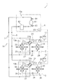
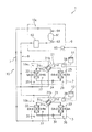
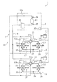
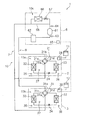
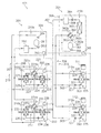
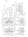
上述の実施形態の熱源ユニット6の熱源側冷媒回路10cにおいて、図22に示されるように、圧縮機構61の吐出側に補助凝縮器66を接続して、圧縮機構61から吐出されて利用ユニット2、3に送られる高圧のガス冷媒の一部を凝縮させることができるようにしてもよい。
(4) Modification In the heat source side refrigerant circuit 10c of the heat source unit 6 of the above-described embodiment, an auxiliary condenser 66 is connected to the discharge side of the compression mechanism 61 and discharged from the compression mechanism 61 as shown in FIG. Then, a part of the high-pressure gas refrigerant sent to the utilization units 2 and 3 may be condensed.

本変形例において、補助凝縮器66は、圧縮機構61の吐出管68の一部をバイパスするように接続されており、圧縮機構61から吐出されて利用ユニット2、3に送られる高圧のガス冷媒の一部をバイパスして凝縮させた後に、再び吐出管68を流れる高圧のガス冷媒に合流させることで、高圧のガス冷媒の圧力を低下させることができるようになっている。しかも、補助凝縮器66の入口側には、電磁弁67が接続されているため、急激な運転負荷の減少が生じた場合等のように、圧縮機構61の吐出圧力が過度に上昇する場合にのみ使用できるようにもなっている。   In this modification, the auxiliary condenser 66 is connected so as to bypass a part of the discharge pipe 68 of the compression mechanism 61, and is a high-pressure gas refrigerant that is discharged from the compression mechanism 61 and sent to the use units 2 and 3. After a part of the gas is bypassed and condensed, it is joined again to the high-pressure gas refrigerant flowing through the discharge pipe 68 so that the pressure of the high-pressure gas refrigerant can be reduced. In addition, since the solenoid valve 67 is connected to the inlet side of the auxiliary condenser 66, when the discharge pressure of the compression mechanism 61 increases excessively, such as when a sudden decrease in operating load occurs. It can only be used.

本変形例では、圧縮機構61の吐出側を流れる冷媒の一部を補助凝縮器66によって凝縮させることによって、圧縮機構61の吐出側の冷媒の圧力を低下させることができる。これにより、空気調和システム1の運転負荷の変動に伴って冷媒循環量が減少することにより圧縮機構61の吐出側の冷媒の圧力が一時的に増加する等の圧力変動が生じる場合であっても、吸着熱交換器22、23、32、33を用いたマルチ空気調和システムを安定的に運転することができる。
[第2実施形態]
(1)空気調和システムの構成
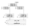
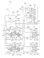
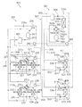
図23は、本発明にかかる第2実施形態の空気調和システム101の概略の冷媒回路図である。空気調和システム101は、蒸気圧縮式の冷凍サイクル運転を行うことによって、ビル等の屋内の潜熱負荷及び顕熱負荷を処理する空気調和システムである。空気調和システム101は、いわゆる、セパレート型のマルチ空気調和システムであり、主として屋内の潜熱負荷を処理する潜熱負荷処理システム201と、主として屋内の顕熱負荷を処理する顕熱負荷処理システム301とを備えている。
In this modification, the pressure of the refrigerant on the discharge side of the compression mechanism 61 can be reduced by condensing a part of the refrigerant flowing on the discharge side of the compression mechanism 61 by the auxiliary condenser 66. As a result, even if the pressure fluctuation occurs such as the refrigerant pressure on the discharge side of the compression mechanism 61 temporarily increases due to the refrigerant circulation amount decreasing with the fluctuation of the operating load of the air conditioning system 1. The multi-air conditioning system using the adsorption heat exchangers 22, 23, 32, and 33 can be stably operated.
[Second Embodiment]
(1) Configuration of Air Conditioning System FIG. 23 is a schematic refrigerant circuit diagram of an air conditioning system 101 according to a second embodiment of the present invention. The air conditioning system 101 is an air conditioning system that processes an indoor latent heat load and a sensible heat load such as a building by performing a vapor compression refrigeration cycle operation. The air conditioning system 101 is a so-called separate type multi-air conditioning system. I have.

潜熱負荷処理システム201は、第1実施形態の空気調和システム1と同様の構成であるため、第1実施形態の利用ユニット2の各部を示す符号をすべて200番台の符号に変え、さらに、各部の名称として「潜熱系統」の文言を付するのみとし(例えば、利用ユニット2は、潜熱系統利用ユニット202とする)、ここでは、各部の説明を省略する。
顕熱負荷処理システム301は、主として、複数台(本実施形態では、2台)の顕熱系統利用ユニット302、303と、顕熱系統熱源ユニット306と、顕熱系統利用ユニット302、303と顕熱系統熱源ユニット306とを接続する顕熱系統連絡配管307、308とを備えている。本実施形態において、顕熱系統熱源ユニット306は、顕熱系統利用ユニット302、303に共通の熱源として機能する。また、本実施形態において、顕熱系統熱源ユニット306は、1台だけであるが、顕熱系統利用ユニット302、303の台数が多い場合等においては複数台を並列に接続していてもよい。
Since the latent heat load processing system 201 has the same configuration as the air conditioning system 1 of the first embodiment, all the symbols indicating the respective parts of the utilization unit 2 of the first embodiment are changed to the codes of the 200 series, Only the word “latent heat system” is added as the name (for example, the utilization unit 2 is the latent heat system utilization unit 202), and description of each part is omitted here.
The sensible heat load processing system 301 mainly includes a plurality of (in this embodiment, two) sensible heat system use units 302 and 303, a sensible heat system heat source unit 306, a sensible heat system use units 302 and 303, and a sensible heat system use unit 302 and 303. Sensible heat system connection pipes 307 and 308 for connecting the heat system heat source unit 306 are provided. In this embodiment, the sensible heat system heat source unit 306 functions as a heat source common to the sensible heat system utilization units 302 and 303. In this embodiment, only one sensible heat system heat source unit 306 is provided. However, when the number of sensible heat system use units 302 and 303 is large, a plurality of sensible heat system heat source units 306 may be connected in parallel.

<顕熱系統利用ユニット>
顕熱系統利用ユニット302、303は、ビル等の屋内の天井に埋め込みや吊り下げ等により、壁掛け等により、又は、天井裏の空間に設置されている。顕熱系統利用ユニット302、303は、顕熱系統連絡配管307、308を介して顕熱系統熱源ユニット306に接続されており、顕熱系統熱源ユニット306との間で顕熱系統冷媒回路310を構成している。顕熱系統利用ユニット302、303は、この顕熱系統冷媒回路310内において冷媒を循環させて蒸気圧縮式の冷凍サイクル運転を行うことによって、主として屋内の顕熱負荷を処理することが可能である。そして、顕熱系統利用ユニット302は潜熱系統利用ユニット202と同じ空調空間に設置されており、顕熱系統利用ユニット303は潜熱系統利用ユニット203と同じ空調空間に設置されている。すなわち、潜熱系統利用ユニット202と顕熱系統利用ユニット302とがペアになって、ある空調空間の潜熱負荷及び顕熱負荷を処理しており、潜熱系統利用ユニット203と顕熱系統利用ユニット303とがペアになって、別の空調空間の潜熱負荷及び顕熱負荷を処理している。
<Sensible heat system use unit>
The sensible heat system utilization units 302 and 303 are installed in an indoor ceiling of a building or the like by being hung or suspended, by wall hanging, or in a space behind the ceiling. The sensible heat system use units 302 and 303 are connected to the sensible heat system heat source unit 306 via the sensible heat system connection pipes 307 and 308, and the sensible heat system heat source unit 306 is connected to the sensible heat system heat source unit 306. It is composed. The sensible heat system utilization units 302 and 303 can mainly handle indoor sensible heat loads by circulating the refrigerant in the sensible heat system refrigerant circuit 310 and performing a vapor compression refrigeration cycle operation. . The sensible heat system utilization unit 302 is installed in the same conditioned space as the latent heat system utilization unit 202, and the sensible heat system utilization unit 303 is installed in the same conditioned space as the latent heat system utilization unit 203. That is, the latent heat system utilization unit 202 and the sensible heat system utilization unit 302 are paired to process a latent heat load and a sensible heat load in a certain air-conditioned space. Are paired to process the latent heat load and sensible heat load of another air-conditioned space.

次に、顕熱系統利用ユニット302、303の構成について説明する。尚、顕熱系統利用ユニット302と顕熱系統利用ユニット303とは同様の構成であるため、ここでは、顕熱系統利用ユニット302の構成のみ説明し、顕熱系統利用ユニット303の構成については、顕熱系統利用ユニット302の各部を示す320番台の符号の代わりに330番台の符号を付して、各部の説明を省略する。   Next, the configuration of the sensible heat system utilization units 302 and 303 will be described. Since the sensible heat system use unit 302 and the sensible heat system use unit 303 have the same configuration, only the configuration of the sensible heat system use unit 302 will be described here. The reference numerals of the 330th series are attached instead of the reference numerals of the 320th series indicating the respective parts of the sensible heat system utilization unit 302, and description of each part is omitted.

顕熱系統利用ユニット302は、主として、顕熱系統冷媒回路310の一部を構成しており、空気を冷却又は加熱することが可能な顕熱系統利用側冷媒回路310aを備えている。この顕熱系統利用側冷媒回路310aは、主として、顕熱系統利用側膨張弁321と、空気熱交換器322とを備えている。本実施形態において、顕熱系統利用側膨張弁321は、冷媒流量の調節等を行うために、空気熱交換器322の液側に接続された電動膨張弁である。本実施形態において、空気熱交換器322は、伝熱管と多数のフィンとにより構成されたクロスフィン式のフィン・アンド・チューブ型熱交換器であり、冷媒と屋内空気RAとの熱交換を行うための機器である。本実施形態において、顕熱系統利用ユニット302は、ユニット内に屋内空気RAを吸入して、熱交換した後に、供給空気SAとして屋内に供給するための送風ファン(図示せず)を備えており、屋内空気RAと空気熱交換器322を流れる冷媒とを熱交換させることが可能である。   The sensible heat system utilization unit 302 mainly constitutes a part of the sensible heat system refrigerant circuit 310, and includes a sensible heat system utilization side refrigerant circuit 310a capable of cooling or heating air. The sensible heat system use side refrigerant circuit 310 a mainly includes a sensible heat system use side expansion valve 321 and an air heat exchanger 322. In the present embodiment, the sensible heat system utilization side expansion valve 321 is an electric expansion valve connected to the liquid side of the air heat exchanger 322 in order to adjust the refrigerant flow rate or the like. In the present embodiment, the air heat exchanger 322 is a cross-fin type fin-and-tube heat exchanger composed of heat transfer tubes and a large number of fins, and performs heat exchange between the refrigerant and the indoor air RA. Equipment. In this embodiment, the sensible heat system utilization unit 302 includes a blower fan (not shown) for supplying indoor air RA as supply air SA after sucking indoor air RA into the unit and exchanging heat. It is possible to exchange heat between the indoor air RA and the refrigerant flowing through the air heat exchanger 322.

また、顕熱系統利用ユニット302には、各種のセンサが設けられている。空気熱交換器322の液側には液冷媒の温度を検出する液側温度センサ323が設けられており、空気熱交換器322のガス側にはガス冷媒の温度を検出するガス側温度センサ324が設けられている。さらに、顕熱系統利用ユニット302には、ユニット内に吸入される屋内空気RAの温度を検出するRA吸入温度センサ325が設けられている。また、顕熱系統利用ユニット302は、顕熱系統利用ユニット302を構成する各部の動作を制御する顕熱系統利用側制御部328を備えている。そして、顕熱系統利用側制御部328は、顕熱系統利用ユニット302の制御を行うために設けられたマイクロコンピュータやメモリを有しており、リモコン111を通じて、屋内の空気の目標温度及び目標湿度の入力信号等のやりとりを行ったり、顕熱系統熱源ユニット306との間で制御信号等のやりとりを行うこともできるようになっている。   The sensible heat system utilization unit 302 is provided with various sensors. A liquid side temperature sensor 323 that detects the temperature of the liquid refrigerant is provided on the liquid side of the air heat exchanger 322, and a gas side temperature sensor 324 that detects the temperature of the gas refrigerant on the gas side of the air heat exchanger 322. Is provided. Further, the sensible heat system utilization unit 302 is provided with an RA suction temperature sensor 325 for detecting the temperature of the indoor air RA sucked into the unit. In addition, the sensible heat system utilization unit 302 includes a sensible heat system utilization side control unit 328 that controls the operation of each part constituting the sensible heat system utilization unit 302. The sensible heat system use side control unit 328 includes a microcomputer and a memory provided to control the sensible heat system use unit 302, and the indoor air target temperature and target humidity are controlled via the remote controller 111. Exchange of input signals and the like, and exchange of control signals and the like with the sensible heat system heat source unit 306 can also be performed.

<顕熱系統熱源ユニット>
顕熱系統熱源ユニット306は、ビル等の屋上等に設置されており、顕熱系統連絡配管307、308を介して顕熱系統利用ユニット302、303に接続されており、顕熱系統利用ユニット302、303との間で顕熱系統冷媒回路310を構成している。
次に、顕熱系統熱源ユニット306の構成について説明する。顕熱系統熱源ユニット306は、主として、顕熱系統冷媒回路310の一部を構成しており、顕熱系統熱源側冷媒回路310cを備えている。この顕熱系統熱源側冷媒回路310cは、主として、顕熱系統圧縮機構361と、顕熱系統熱源側四路切換弁362と、顕熱系統熱源側熱交換器363と、顕熱系統熱源側膨張弁364と、顕熱系統レシーバ368とを備えている。
<Sensible heat system heat source unit>
The sensible heat system heat source unit 306 is installed on the rooftop of a building or the like, and is connected to the sensible heat system utilization units 302 and 303 via the sensible heat system connection pipes 307 and 308. , 303 constitutes the sensible heat system refrigerant circuit 310.
Next, the configuration of the sensible heat system heat source unit 306 will be described. The sensible heat system heat source unit 306 mainly constitutes a part of the sensible heat system refrigerant circuit 310, and includes a sensible heat system heat source side refrigerant circuit 310c. The sensible heat system heat source side refrigerant circuit 310c mainly includes a sensible heat system compression mechanism 361, a sensible heat system heat source side four-way switching valve 362, a sensible heat system heat source side heat exchanger 363, and a sensible heat system heat source side expansion. A valve 364 and a sensible heat system receiver 368 are provided.

顕熱系統圧縮機構361は、本実施形態において、インバータ制御により運転容量を可変することが可能な容積式圧縮機である。本実施形態において、顕熱系統圧縮機構361は、1台の圧縮機であるが、これに限定されず、顕熱系統利用ユニットの接続台数等に応じて、2台以上の圧縮機が並列に接続されたものであってもよい。
顕熱系統熱源側四路切換弁362は、冷房運転と暖房運転との切り換え時に、顕熱系統熱源側冷媒回路310c内における冷媒の流路を切り換えるための弁であり、その第1ポート362aは顕熱系統圧縮機構361の吐出側に接続されており、その第2ポート362bは顕熱系統圧縮機構361の吸入側に接続されており、その第3ポート362cは顕熱系統熱源側熱交換器363のガス側端部に接続されており、その第4ポート362dは顕熱系統ガス連絡配管308に接続されている。そして、顕熱系統熱源側四路切換弁362は、第1ポート362aと第3ポート362cとを接続するとともに第2ポート362bと第4ポート362dとを接続(冷房運転状態、図23の顕熱系統熱源側四路切換弁362の実線を参照)したり、第1ポート362aと第4ポート362dとを接続するとともに第2ポート362bと第3ポート362cとを接続(暖房運転状態、図23の顕熱系統熱源側四路切換弁362の破線を参照)する切り換えを行うことが可能である。
In the present embodiment, the sensible heat system compression mechanism 361 is a positive displacement compressor capable of varying the operation capacity by inverter control. In this embodiment, the sensible heat system compression mechanism 361 is a single compressor, but is not limited to this, and two or more compressors are connected in parallel according to the number of connected sensible heat system utilization units. It may be connected.
The sensible heat system heat source side four-way switching valve 362 is a valve for switching the flow path of the refrigerant in the sensible heat system heat source side refrigerant circuit 310c when switching between the cooling operation and the heating operation, and the first port 362a thereof is The sensible heat system compression mechanism 361 is connected to the discharge side, the second port 362b is connected to the suction side of the sensible heat system compression mechanism 361, and the third port 362c is the sensible heat system heat source side heat exchanger. The third port 362 d is connected to the sensible heat system gas communication pipe 308. The sensible heat system heat source side four-way switching valve 362 connects the first port 362a and the third port 362c and connects the second port 362b and the fourth port 362d (cooling operation state, sensible heat in FIG. 23). System heat source side four-way switching valve 362 (see the solid line), and the first port 362a and the fourth port 362d are connected and the second port 362b and the third port 362c are connected (heating operation state, FIG. 23) It is possible to perform switching that refers to the broken line of the sensible heat system heat source side four-way switching valve 362).

顕熱系統熱源側熱交換器363は、本実施形態において、伝熱管と多数のフィンとにより構成されたクロスフィン式のフィン・アンド・チューブ型熱交換器であり、空気を熱源として冷媒と熱交換するための機器である。本実施形態において、顕熱系統熱源ユニット306は、ユニット内に屋外の空気を取り込み、送り出すための室外ファン(図示せず)を備えており、屋外の空気と顕熱系統熱源側熱交換器363を流れる冷媒とを熱交換させることが可能である。   In the present embodiment, the sensible heat system heat source side heat exchanger 363 is a cross-fin type fin-and-tube heat exchanger composed of heat transfer tubes and a large number of fins. It is equipment for exchange. In the present embodiment, the sensible heat system heat source unit 306 includes an outdoor fan (not shown) for taking in and sending outdoor air into the unit, and the outdoor air and sensible heat system heat source side heat exchanger 363. It is possible to exchange heat with the refrigerant flowing through

顕熱系統熱源側膨張弁364は、本実施形態において、顕熱系統液連絡配管307を介して顕熱系統熱源側熱交換器363と空気熱交換器322、332との間を流れる冷媒の流量の調節等を行うことが可能な電動膨張弁である。顕熱系統熱源側膨張弁364は、冷房運転時にはほぼ全開状態で使用され、暖房運転時には開度調節されて空気熱交換器322、332から顕熱系統液連絡配管307を介して顕熱系統熱源側熱交換器363に流入する冷媒を減圧するのに使用される。   In the present embodiment, the sensible heat system heat source side expansion valve 364 is a flow rate of the refrigerant flowing between the sensible heat system heat source side heat exchanger 363 and the air heat exchangers 322 and 332 via the sensible heat system liquid communication pipe 307. It is an electric expansion valve capable of adjusting the above. The sensible heat system heat source side expansion valve 364 is used in a substantially fully opened state during the cooling operation, and the opening degree is adjusted during the heating operation, and the sensible heat system heat source is supplied from the air heat exchangers 322 and 332 via the sensible heat system liquid connection pipe 307. Used to depressurize the refrigerant flowing into the side heat exchanger 363.

顕熱系統レシーバ368は、顕熱系統熱源側熱交換器363と空気熱交換器322、332との間を流れる冷媒を一時的に溜めるための容器である。本実施形態において、顕熱系統レシーバ368は、顕熱系統熱源側膨張弁364と顕熱系統液連絡配管307との間に接続されている。
また、顕熱系統熱源ユニット306には、各種のセンサが設けられている。具体的には、顕熱系統熱源ユニット306は、顕熱系統圧縮機構361の吸入圧力を検出する顕熱系統吸入圧力センサ366と、顕熱系統圧縮機構361の吐出圧力を検出する顕熱系統吐出圧力センサ367と、顕熱系統熱源ユニット306を構成する各部の動作を制御する顕熱系統熱源側制御部365とを備えている。そして、顕熱系統熱源側制御部365は、顕熱系統熱源ユニット306の制御を行うために設けられたマイクロコンピュータやメモリを有しており、顕熱系統利用ユニット302、303の顕熱系統利用側制御部328、338との間で制御信号を伝送できるようになっている。また、顕熱系統熱源側制御部365は、潜熱系統熱源側制御部265との間でも制御信号等のやりとりを行うことができるようになっている。さらに、顕熱系統熱源側制御部365は、潜熱系統熱源側制御部265を介して潜熱系統利用側制御部228、238との間でも制御信号のやりとりを行うことができるようになっている。
The sensible heat system receiver 368 is a container for temporarily storing the refrigerant flowing between the sensible heat system heat source side heat exchanger 363 and the air heat exchangers 322 and 332. In the present embodiment, the sensible heat system receiver 368 is connected between the sensible heat system heat source side expansion valve 364 and the sensible heat system liquid communication pipe 307.
The sensible heat system heat source unit 306 is provided with various sensors. Specifically, the sensible heat system heat source unit 306 includes a sensible heat system suction pressure sensor 366 that detects the suction pressure of the sensible heat system compression mechanism 361 and a sensible heat system discharge that detects the discharge pressure of the sensible heat system compression mechanism 361. A pressure sensor 367 and a sensible heat system heat source side control unit 365 that controls the operation of each part constituting the sensible heat system heat source unit 306 are provided. The sensible heat system heat source side control unit 365 includes a microcomputer and a memory provided for controlling the sensible heat system heat source unit 306, and uses the sensible heat system utilization units 302 and 303 for sensible heat system utilization. Control signals can be transmitted between the side control units 328 and 338. In addition, the sensible heat system heat source side control unit 365 can exchange control signals and the like with the latent heat system heat source side control unit 265. Further, the sensible heat system heat source side control unit 365 can exchange control signals with the latent heat system use side control units 228 and 238 via the latent heat system heat source side control unit 265.

(2)空気調和システムの動作
次に、本実施形態の空気調和システム101の動作について説明する。空気調和システム101は、屋内の潜熱負荷を潜熱負荷処理システム201で処理し、屋内の顕熱負荷を主として顕熱負荷処理システム301で処理することができる。以下に、各種の運転動作について説明する。
(2) Operation | movement of an air conditioning system Next, operation | movement of the air conditioning system 101 of this embodiment is demonstrated. The air conditioning system 101 can process an indoor latent heat load by the latent heat load processing system 201 and can process an indoor sensible heat load mainly by the sensible heat load processing system 301. Below, various driving | operation operations are demonstrated.

<除湿冷房運転>
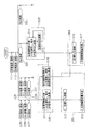
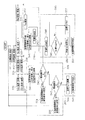
まず、潜熱負荷処理システム201を全換気モードで除湿運転を行いつつ、顕熱負荷処理システム301で冷房運転を行う冷房除湿運転における動作について、図24、図25及び図26を用いて説明する。ここで、図24及び図25は、空気調和システム101における全換気モードの除湿冷房運転時の動作を示す概略の冷媒回路図である。図26は、空気調和システム101における通常運転時の制御フロー図である。尚、図26においては、潜熱系統利用ユニット202及び顕熱系統利用ユニット302のペアと潜熱系統利用ユニット203及び顕熱系統利用ユニット303のペアとは同様の制御フローであるため、潜熱系統利用ユニット202及び顕熱系統利用ユニット303のペアの制御フローの図示を省略している。
<Dehumidifying and cooling operation>
First, the operation in the cooling and dehumidifying operation in which the latent heat load processing system 201 is dehumidified in the full ventilation mode and the sensible heat load processing system 301 performs the cooling operation will be described with reference to FIGS. 24, 25, and 26. Here, FIG. 24 and FIG. 25 are schematic refrigerant circuit diagrams showing the operation during the dehumidifying and cooling operation in the total ventilation mode in the air conditioning system 101. FIG. 26 is a control flow diagram during normal operation in the air conditioning system 101. In FIG. 26, the latent heat system utilization unit 202 and the sensible heat system utilization unit 302 pair and the latent heat system utilization unit 203 and the sensible heat system utilization unit 303 pair have the same control flow. The control flow of a pair of 202 and the sensible heat system utilization unit 303 is not shown.

まず、潜熱負荷処理システム201の動作について説明する。
潜熱負荷処理システム201の潜熱系統利用ユニット202においては、上述の潜熱負荷処理システム201の単独運転時の場合と同様に、第1吸着熱交換器222が凝縮器となって第2吸着熱交換器223が蒸発器となる第1動作と、第2吸着熱交換器223が凝縮器となって第1吸着熱交換器222が蒸発器となる第2動作とが交互に繰り返される。潜熱系統利用ユニット203においても同様に、第1吸着熱交換器232が凝縮器となって第2吸着熱交換器233が蒸発器となる第1動作と、第2吸着熱交換器233が凝縮器となって第1吸着熱交換器232が蒸発器となる第2動作とが交互に繰り返される。
First, the operation of the latent heat load processing system 201 will be described.
In the latent heat system utilization unit 202 of the latent heat load processing system 201, the first adsorption heat exchanger 222 serves as a condenser as in the case of the single operation of the latent heat load processing system 201 described above. The first operation in which 223 is an evaporator and the second operation in which the second adsorption heat exchanger 223 is a condenser and the first adsorption heat exchanger 222 is an evaporator are alternately repeated. Similarly, in the latent heat system use unit 203, the first operation in which the first adsorption heat exchanger 232 serves as a condenser and the second adsorption heat exchanger 233 serves as an evaporator, and the second adsorption heat exchanger 233 serves as a condenser. Thus, the second operation in which the first adsorption heat exchanger 232 becomes an evaporator is alternately repeated.

以下の説明では、2つの潜熱系統利用ユニット202、203の動作をまとめて記載する。
第1動作では、第1吸着熱交換器222、232についての再生動作と、第2吸着熱交換器223、233についての吸着動作とが並行して行われる。第1動作中は、図24に示されるように、潜熱系統利用側四路切換弁221、231が第1状態(図24の潜熱系統利用側四路切換弁221、231の実線を参照)に設定される。この状態で、潜熱系統圧縮機構261から吐出された高圧のガス冷媒は、潜熱系統吐出ガス連絡配管207、潜熱系統利用側四路切換弁221、231を通じて第1吸着熱交換器222、232に流入し、第1吸着熱交換器222、232を通過する間に凝縮する。そして、凝縮された冷媒は、潜熱系統利用側膨張弁224、234で減圧されて、その後、第2吸着熱交換器223、233を通過する間に蒸発し、潜熱系統利用側四路切換弁221、231、潜熱系統吸入ガス連絡配管208、潜熱系統アキュムレータ262を通じて潜熱系統圧縮機構261に再び吸入される(図24の潜熱系統冷媒回路210に付された矢印を参照)。
In the following description, the operations of the two latent heat system use units 202 and 203 will be described together.
In the first operation, the regeneration operation for the first adsorption heat exchangers 222 and 232 and the adsorption operation for the second adsorption heat exchangers 223 and 233 are performed in parallel. During the first operation, as shown in FIG. 24, the latent heat system use-side four-way switching valves 221 and 231 are in the first state (see the solid lines of the latent heat system use-side four-way switching valves 221 and 231). Is set. In this state, the high-pressure gas refrigerant discharged from the latent heat system compression mechanism 261 flows into the first adsorption heat exchangers 222 and 232 through the latent heat system discharge gas communication pipe 207 and the latent heat system use-side four-way switching valves 221 and 231. And condensed while passing through the first adsorption heat exchangers 222 and 232. The condensed refrigerant is depressurized by the latent heat system use side expansion valves 224 and 234 and then evaporated while passing through the second adsorption heat exchangers 223 and 233, and the latent heat system use side four-way switching valve 221 is used. 231, the latent heat system intake gas communication pipe 208, and the latent heat system accumulator 262 are again sucked into the latent heat system compression mechanism 261 (see the arrow attached to the latent heat system refrigerant circuit 210 in FIG. 24).

第1動作中において、第1吸着熱交換器222、232では、冷媒の凝縮により加熱された吸着剤から水分が脱離し、この脱離した水分が内気吸入口から吸入された屋内空気RAに付与される。第1吸着熱交換器222、232から脱離した水分は、屋内空気RAに同伴して排気口を通じて排出空気EAとして屋外へ排出される。第2吸着熱交換器223、233では、屋外空気OA中の水分が吸着剤に吸着されて屋外空気OAが除湿され、その際に生じた吸着熱が冷媒に吸熱されて冷媒が蒸発する。そして、第2吸着熱交換器223、233で除湿された屋外空気OAは、給気口を通って供給空気SAとして屋内へ供給される(図24の吸着熱交換器222、223、232、233の両側に付された矢印を参照)。   During the first operation, in the first adsorption heat exchangers 222 and 232, moisture is desorbed from the adsorbent heated by the condensation of the refrigerant, and the desorbed moisture is given to the indoor air RA sucked from the inside air intake port. Is done. The moisture desorbed from the first adsorption heat exchangers 222 and 232 is exhausted to the outdoors as exhaust air EA through the exhaust port accompanying the indoor air RA. In the second adsorption heat exchangers 223 and 233, the moisture in the outdoor air OA is adsorbed by the adsorbent and the outdoor air OA is dehumidified, and the adsorption heat generated at that time is absorbed by the refrigerant and the refrigerant evaporates. Then, the outdoor air OA dehumidified by the second adsorption heat exchangers 223, 233 is supplied indoors as supply air SA through the air supply port (adsorption heat exchangers 222, 223, 232, 233 in FIG. 24). (See arrows on both sides of the).

第2動作では、第1吸着熱交換器222、232についての吸着動作と、第2吸着熱交換器223、233についての再生動作とが並行して行われる。第2動作中は、図25に示されるように、潜熱系統利用側四路切換弁221、231が第2状態(図25の潜熱系統利用側四路切換弁221、231の破線を参照)に設定される。この状態で、潜熱系統圧縮機構261から吐出された高圧のガス冷媒は、潜熱系統吐出ガス連絡配管207、潜熱系統利用側四路切換弁221、231を通じて第2吸着熱交換器223、233に流入し、第2吸着熱交換器223、233を通過する間に凝縮する。そして、凝縮された冷媒は、潜熱系統利用側膨張弁224、234で減圧されて、その後、第1吸着熱交換器222、232を通過する間に蒸発し、潜熱系統利用側四路切換弁221、231、潜熱系統吸入ガス連絡配管208、潜熱系統アキュムレータ262を通じて潜熱系統圧縮機構261に再び吸入される(図25の潜熱系統冷媒回路210に付された矢印を参照)。   In the second operation, the adsorption operation for the first adsorption heat exchangers 222 and 232 and the regeneration operation for the second adsorption heat exchangers 223 and 233 are performed in parallel. During the second operation, as shown in FIG. 25, the latent heat system use-side four-way switching valves 221 and 231 are in the second state (see the broken lines of the latent heat system use-side four-way switching valves 221 and 231 in FIG. 25). Is set. In this state, the high-pressure gas refrigerant discharged from the latent heat system compression mechanism 261 flows into the second adsorption heat exchangers 223 and 233 through the latent heat system discharge gas communication pipe 207 and the latent heat system use side four-way switching valves 221 and 231. And condensed while passing through the second adsorption heat exchangers 223 and 233. The condensed refrigerant is depressurized by the latent heat system use side expansion valves 224 and 234 and then evaporated while passing through the first adsorption heat exchangers 222 and 232, and the latent heat system use side four-way switching valve 221. 231, the latent heat system intake gas communication pipe 208 and the latent heat system accumulator 262 are again sucked into the latent heat system compression mechanism 261 (see the arrow attached to the latent heat system refrigerant circuit 210 in FIG. 25).

第2動作中において、第2吸着熱交換器223、233では、冷媒の凝縮により加熱された吸着剤から水分が脱離し、この脱離した水分が内気吸入口から吸入された屋内空気RAに付与される。第2吸着熱交換器23、33から脱離した水分は、屋内空気RAに同伴して排気口を通じて排出空気EAとして屋外へ排出される。第1吸着熱交換器222、232では、屋外空気OA中の水分が吸着剤に吸着されて屋外空気OAが除湿され、その際に生じた吸着熱が冷媒に吸熱されて冷媒が蒸発する。そして、第1吸着熱交換器222、232で除湿された屋外空気OAは、給気口を通って供給空気SAとして屋内へ供給される(図25の吸着熱交換器222、223、232、233の両側に付された矢印を参照)。   During the second operation, in the second adsorption heat exchangers 223 and 233, moisture is desorbed from the adsorbent heated by the condensation of the refrigerant, and the desorbed moisture is given to the indoor air RA sucked from the inside air intake port. Is done. The moisture desorbed from the second adsorption heat exchangers 23 and 33 is accompanied by the indoor air RA and discharged to the outdoors as exhaust air EA through the exhaust port. In the first adsorption heat exchangers 222 and 232, the moisture in the outdoor air OA is adsorbed by the adsorbent and the outdoor air OA is dehumidified, and the adsorption heat generated at that time is absorbed by the refrigerant and the refrigerant evaporates. The outdoor air OA dehumidified by the first adsorption heat exchangers 222 and 232 is supplied indoors as supply air SA through the air supply port (adsorption heat exchangers 222, 223, 232, and 233 in FIG. 25). (See arrows on both sides of the).

ここで、空気調和システム101において行われているシステム制御について、潜熱負荷処理システム201に着目して説明する。
まず、リモコン111、112によって目標温度及び目標相対湿度が設定されると、潜熱系統利用ユニット202、203の潜熱系統利用側制御部228、238には、これらの目標温度値及び目標相対湿度値とともに、RA吸入温度・湿度センサ225、235によって検出されたユニット内に吸入される屋内の空気の温度値及び相対湿度値と、OA吸入温度・湿度センサ226、236によって検出されたユニット内に吸入される屋外の空気の温度値及び相対湿度値とが入力される。
Here, the system control performed in the air conditioning system 101 will be described by focusing on the latent heat load processing system 201.
First, when the target temperature and the target relative humidity are set by the remote controllers 111 and 112, the latent heat system use side control units 228 and 238 of the latent heat system use units 202 and 203 have the target temperature value and the target relative humidity value. The indoor air temperature value and relative humidity value sucked into the unit detected by the RA suction temperature / humidity sensors 225, 235, and the unit detected by the OA suction temperature / humidity sensors 226, 236 are sucked into the unit. The outdoor air temperature value and relative humidity value are input.

すると、ステップS11において、潜熱系統利用側制御部228、238は、屋内の空気の目標温度値及び目標相対湿度値からエンタルピの目標値又は絶対湿度の目標値を演算し、そして、RA吸入温度・湿度センサ225、235によって検出された温度値及び相対湿度値から屋内からユニット内に吸入される空気のエンタルピの現在値又は絶対湿度の現在値を演算し、両値の差である必要潜熱能力値Δhを演算する。そして、このΔhの値を、潜熱系統利用ユニット202、203の処理能力を上げる必要があるかどうかを潜熱系統熱源側制御部265に知らせるための能力UP信号K1に変換する。例えば、Δhの絶対値が所定値よりも小さい場合(すなわち、屋内の空気の湿度値が目標湿度値に近い値であり、処理能力を増減する必要がない場合)には能力UP信号K1を「0」とし、Δhの絶対値が所定値よりも処理能力を上げなければならない方向に大きい場合(すなわち、除湿運転においては屋内の空気の湿度値が目標湿度値よりも高く、処理能力を上げる必要がある場合)には能力UP信号K1を「A」とし、Δhの絶対値が所定値よりも処理能力を下げなければならない方向に大きい場合(すなわち、除湿運転においては屋内の空気の湿度値が目標湿度値よりも低く、処理能力を下げる必要がある場合)には能力UP信号K1を「B」とする。   Then, in step S11, the latent heat system use side control units 228 and 238 calculate the target value of enthalpy or the target value of absolute humidity from the target temperature value and target relative humidity value of indoor air, The current value of the enthalpy of air sucked into the unit from the indoor or the current value of the absolute humidity is calculated from the temperature value and the relative humidity value detected by the humidity sensors 225 and 235, and the necessary latent heat capacity value which is the difference between the two values Δh is calculated. Then, the value of Δh is converted into a capability UP signal K1 for notifying the latent heat system heat source side control unit 265 whether or not the processing capacity of the latent heat system utilization units 202 and 203 needs to be increased. For example, when the absolute value of Δh is smaller than a predetermined value (that is, when the humidity value of indoor air is close to the target humidity value and there is no need to increase or decrease the processing capacity), the capability UP signal K1 is set to “ 0, and when the absolute value of Δh is larger than the predetermined value in the direction in which the processing capacity must be increased (that is, in the dehumidifying operation, the humidity value of indoor air is higher than the target humidity value and the processing capacity needs to be increased) When the capacity UP signal K1 is “A” and the absolute value of Δh is larger than the predetermined value in the direction in which the processing capacity must be lowered (that is, in the dehumidifying operation, the humidity value of the indoor air is When the humidity is lower than the target humidity value and the processing capacity needs to be lowered, the capacity UP signal K1 is set to “B”.

次に、ステップS12において、潜熱系統熱源側制御部265は、潜熱系統利用側制御部228、238から潜熱系統熱源側制御部265へ伝送された潜熱系統利用ユニット202、203の能力UP信号K1を用いて、目標凝縮温度値TcS1及び目標蒸発温度値TeS1を演算する。例えば、目標凝縮温度値TcS1は、現在の目標凝縮温度値に潜熱系統利用ユニット202、203の能力UP信号K1を加算することによって演算される。また、目標蒸発温度値TeS1は、現在の目標蒸発温度値に潜熱系統利用ユニット202、203の能力UP信号K1を減算することによって演算される。これにより、能力UP信号K1の値が「A」の場合には、目標凝縮温度値TcS1は高くなり、目標蒸発温度値TeS1は低くなる。   Next, in step S12, the latent heat system heat source side control unit 265 receives the capability UP signal K1 of the latent heat system utilization units 202 and 203 transmitted from the latent heat system utilization side control units 228 and 238 to the latent heat system heat source side control unit 265. The target condensing temperature value TcS1 and the target evaporating temperature value TeS1 are calculated. For example, the target condensation temperature value TcS1 is calculated by adding the capability UP signal K1 of the latent heat system utilization units 202 and 203 to the current target condensation temperature value. Further, the target evaporation temperature value TeS1 is calculated by subtracting the capability UP signal K1 of the latent heat system use units 202 and 203 from the current target evaporation temperature value. Thereby, when the value of the capability UP signal K1 is “A”, the target condensing temperature value TcS1 becomes high and the target evaporation temperature value TeS1 becomes low.

次に、ステップS13において、潜熱負荷処理システム201全体の凝縮温度及び蒸発温度の実測値に相当する値であるシステム凝縮温度値Tc1及びシステム蒸発温度値Te1を演算する。例えば、システム凝縮温度値Tc1及びシステム蒸発温度値Te1は、潜熱系統吸入圧力センサ263によって検出された潜熱系統圧縮機構261の吸入圧力値及び潜熱系統吐出圧力センサ264によって検出された潜熱系統圧縮機構261の吐出圧力値を、これらの圧力値における冷媒の飽和温度に換算することによって演算される。そして、システム凝縮温度値Tc1に対する目標凝縮温度値TcS1の温度差ΔTc1及びシステム蒸発温度値Te1に対する目標蒸発温度値TeS1の温度差ΔTe1を演算し、これらの温度差を除算することによって潜熱系統圧縮機構261の運転容量の増減の要否及び増減幅を決定する。   Next, in step S13, a system condensing temperature value Tc1 and a system evaporating temperature value Te1 that are values corresponding to actual measured values of the condensing temperature and the evaporating temperature of the entire latent heat load processing system 201 are calculated. For example, the system condensation temperature value Tc1 and the system evaporation temperature value Te1 are the suction pressure value of the latent heat system compression mechanism 261 detected by the latent heat system suction pressure sensor 263 and the latent heat system compression mechanism 261 detected by the latent heat system discharge pressure sensor 264. Is calculated by converting the discharge pressure value to the saturation temperature of the refrigerant at these pressure values. Then, a temperature difference ΔTc1 of the target condensing temperature value TcS1 with respect to the system condensing temperature value Tc1 and a temperature difference ΔTe1 of the target evaporating temperature value TeS1 with respect to the system evaporating temperature value Te1 are calculated, and the latent heat system compression mechanism is divided by dividing these temperature differences. The necessity of increase / decrease in the operating capacity 261 and the increase / decrease range are determined.

このようにして決定された潜熱系統圧縮機構261の運転容量を用いて、潜熱系統圧縮機構261の運転容量を制御することで、屋内の空気の目標相対湿度に近づけるシステム制御を行っている。例えば、温度差ΔTc1から温度差ΔTe1を差し引いた値が正値の場合には潜熱系統圧縮機構261の運転容量を増加させ、逆に、温度差ΔTc1から温度差ΔTe1を差し引いた値が負値の場合には潜熱系統圧縮機構261の運転容量を減少させるように制御する。   By using the operation capacity of the latent heat system compression mechanism 261 determined in this way, the operation capacity of the latent heat system compression mechanism 261 is controlled to perform system control to bring it closer to the target relative humidity of indoor air. For example, when the value obtained by subtracting the temperature difference ΔTe1 from the temperature difference ΔTc1 is a positive value, the operating capacity of the latent heat system compression mechanism 261 is increased, and conversely, the value obtained by subtracting the temperature difference ΔTe1 from the temperature difference ΔTc1 is a negative value. In this case, control is performed so as to reduce the operating capacity of the latent heat system compression mechanism 261.

次に、顕熱負荷処理システム301の動作について説明する。
顕熱負荷処理システム301の顕熱系統熱源ユニット306の顕熱系統熱源側四路切換弁362が冷房運転状態(第1ポート362aと第3ポート362cとが接続され、かつ、第2ポート362bと第4ポート362dとが接続された状態)になっている。また、顕熱系統利用ユニット302、303の顕熱系統利用側膨張弁321、331は、冷媒を減圧するように開度調節されている。顕熱系統熱源側膨張弁364は開けられた状態になっている。
Next, the operation of the sensible heat load processing system 301 will be described.
The sensible heat system heat source side four-way switching valve 362 of the sensible heat system heat source unit 306 of the sensible heat load processing system 301 is in a cooling operation state (the first port 362a and the third port 362c are connected, and the second port 362b The fourth port 362d is connected). Moreover, the opening degree of the sensible heat system utilization side expansion valves 321 and 331 of the sensible heat system utilization units 302 and 303 is adjusted so as to depressurize the refrigerant. The sensible heat system heat source side expansion valve 364 is opened.

このような顕熱系統冷媒回路310の状態において、顕熱系統熱源ユニット306の顕熱系統圧縮機構361を起動すると、顕熱系統圧縮機構361から吐出された高圧のガス冷媒は、顕熱系統熱源側四路切換弁362を通過して顕熱系統熱源側熱交換器363に流入し凝縮されて液冷媒となる。この液冷媒は、顕熱系統熱源側膨張弁364、顕熱系統レシーバ368及び顕熱系統液連絡配管307を通じて、顕熱系統利用ユニット302、303に送られる。そして、顕熱系統利用ユニット302、303に送られた液冷媒は、顕熱系統利用側膨張弁321、331で減圧された後、空気熱交換器322、332において、ユニット内に吸入された屋内空気RAとの熱交換によって蒸発して低圧のガス冷媒となる。このガス冷媒は、顕熱系統ガス連絡配管308を通じて顕熱系統熱源ユニット306の顕熱系統圧縮機構361に再び吸入される。一方、空気熱交換器322、332において冷媒との熱交換により冷却された屋内空気RAは、供給空気SAとして屋内に供給される。尚、顕熱系統利用側膨張弁321、331は、後述のように、空気熱交換器322、332における過熱度SH、すなわち、液側温度センサ323、333によって検出された空気熱交換器322、332の液側の冷媒温度値と、ガス側温度センサ324、334によって検出された空気熱交換器322、332のガス側の冷媒温度値との温度差が目標過熱度SHSになるように開度制御がなされている。   In such a state of the sensible heat system refrigerant circuit 310, when the sensible heat system compression mechanism 361 of the sensible heat system heat source unit 306 is activated, the high-pressure gas refrigerant discharged from the sensible heat system compression mechanism 361 becomes the sensible heat system heat source. It passes through the side four-way switching valve 362 and flows into the sensible heat system heat source side heat exchanger 363 and is condensed to become a liquid refrigerant. This liquid refrigerant is sent to the sensible heat system utilization units 302 and 303 through the sensible heat system heat source side expansion valve 364, the sensible heat system receiver 368, and the sensible heat system liquid communication pipe 307. The liquid refrigerant sent to the sensible heat system utilization units 302 and 303 is depressurized by the sensible heat system utilization side expansion valves 321 and 331, and then taken indoors by the air heat exchangers 322 and 332. It evaporates by heat exchange with the air RA and becomes a low-pressure gas refrigerant. This gas refrigerant is again drawn into the sensible heat system compression mechanism 361 of the sensible heat system heat source unit 306 through the sensible heat system gas communication pipe 308. On the other hand, the indoor air RA cooled by the heat exchange with the refrigerant in the air heat exchangers 322 and 332 is supplied indoors as the supply air SA. As will be described later, the sensible heat system use side expansion valves 321 and 331 have superheat degree SH in the air heat exchangers 322 and 332, that is, the air heat exchanger 322 detected by the liquid side temperature sensors 323 and 333, The opening degree is such that the temperature difference between the liquid side refrigerant temperature value 332 and the gas side refrigerant temperature value of the air heat exchangers 322 and 332 detected by the gas side temperature sensors 324 and 334 becomes the target superheat degree SHS. Control is being made.

ここで、空気調和システム101において行われているシステム制御について、顕熱負荷処理システム301に着目して説明する。
まず、リモコン111、112によって目標温度が設定されると、顕熱系統利用ユニット302、303の顕熱系統利用側制御部328、338には、これらの目標温度値とともに、RA吸入温度センサ325、335によって検出されたユニット内に吸入される屋内の空気の温度値が入力される。
Here, the system control performed in the air conditioning system 101 will be described by focusing on the sensible heat load processing system 301.
First, when the target temperature is set by the remote controllers 111 and 112, the sensible heat system use side control units 328 and 338 of the sensible heat system use units 302 and 303 have the RA intake temperature sensor 325, The temperature value of the indoor air sucked into the unit detected by 335 is input.

すると、ステップS14において、顕熱系統利用側制御部328、338は、屋内の空気の目標温度値とRA吸入温度・湿度センサ225、235によって検出された温度値との温度差(以下、必要顕熱能力値ΔTとする)を演算する。ここで、必要顕熱能力値ΔTは、上述のように屋内の空気の目標温度値と現在の屋内の空気の温度値との差であるため、空気調和システム101において処理しなければならない顕熱負荷に相当するものである。そして、この必要顕熱能力値ΔTの値を、顕熱系統利用ユニット302、303の処理能力を上げる必要があるかどうかを顕熱系統熱源側制御部365に知らせるための能力UP信号K2に変換する。例えば、ΔTの絶対値が所定値よりも小さい場合(すなわち、屋内の空気の温度値が目標温度値に近い値であり、処理能力を増減する必要がない場合)には能力UP信号K2を「0」とし、ΔTの絶対値が所定値よりも処理能力を上げなければならない方向に大きい場合(すなわち、冷房運転においては屋内の空気の温度値が目標温度値よりも高く、処理能力を上げる必要がある場合)には能力UP信号K2を「a」とし、ΔTの絶対値が所定値よりも処理能力を下げなければならない方向に大きい場合(すなわち、冷房運転においては屋内の空気の温度値が目標温度値よりも低く、処理能力を下げる必要がある場合)には能力UP信号K2を「b」とする。   Then, in step S14, the sensible heat system use side control units 328 and 338 determine the temperature difference between the target temperature value of the indoor air and the temperature value detected by the RA inhalation temperature / humidity sensors 225 and 235 (hereinafter, necessary sensible temperature). Heat capacity value ΔT). Here, since the required sensible heat capacity value ΔT is the difference between the target temperature value of indoor air and the current temperature value of indoor air as described above, the sensible heat that must be processed in the air conditioning system 101. It corresponds to a load. Then, the value of the required sensible heat capacity value ΔT is converted into a capacity UP signal K2 for informing the sensible heat system heat source side control unit 365 whether or not it is necessary to increase the processing capacity of the sensible heat system utilization units 302 and 303. To do. For example, when the absolute value of ΔT is smaller than a predetermined value (that is, when the temperature value of indoor air is close to the target temperature value and there is no need to increase or decrease the processing capacity), the capability UP signal K2 is set to “ 0, and the absolute value of ΔT is larger than the predetermined value in the direction in which the processing capacity must be increased (that is, in the cooling operation, the temperature value of the indoor air is higher than the target temperature value and the processing capacity needs to be increased). When the capacity UP signal K2 is “a” and the absolute value of ΔT is larger than the predetermined value in the direction in which the processing capacity must be lowered (that is, in the cooling operation, the temperature value of the indoor air is When the temperature is lower than the target temperature value and the processing capacity needs to be lowered), the capacity UP signal K2 is set to “b”.

次に、ステップS15において、顕熱系統利用側制御部328、338は、必要顕熱能力値ΔTの値に応じて、目標過熱度SHSの値を変更する。例えば、顕熱系統利用ユニット302、303の処理能力を下げる必要がある場合(能力UP信号K2が「b」の場合)には、目標過熱度SHSを大きくして、空気熱交換器322、332における冷媒と空気との交換熱量を小さくするように顕熱系統利用側膨張弁321、331の開度を制御する。   Next, in step S15, the sensible heat system use side control units 328 and 338 change the value of the target superheat degree SHS according to the value of the required sensible heat capacity value ΔT. For example, when it is necessary to reduce the processing capacity of the sensible heat system utilization units 302 and 303 (when the capacity UP signal K2 is “b”), the target superheat degree SHS is increased and the air heat exchangers 322 and 332 are increased. The opening degree of the sensible heat system use side expansion valves 321 and 331 is controlled so as to reduce the amount of heat exchanged between the refrigerant and the air.

また、ステップS16において、顕熱系統熱源側制御部365は、顕熱系統利用側制御部328、338から顕熱系統熱源側制御部365へ伝送された顕熱系統利用ユニット302、303の能力UP信号K2を用いて、目標凝縮温度値TcS2及び目標蒸発温度値TeS2を演算する。例えば、目標凝縮温度値TcS2は、現在の目標凝縮温度値に顕熱系統利用ユニット302、303の能力UP信号K2を加算することによって演算される。また、目標蒸発温度値TeS2は、現在の目標蒸発温度値に顕熱系統利用ユニット302、303の能力UP信号K2を減算することによって演算される。これにより、能力UP信号K2の値が「a」の場合には、目標凝縮温度TcS2は高くなり、目標蒸発温度値TeS2は低くなる。尚、上述したように、潜熱負荷処理システム201においては潜熱処理とともに顕熱処理が行われるため、目標凝縮温度値TcS2及び目標蒸発温度値TeS2の演算をするにあたり、潜熱負荷処理システム201において潜熱負荷の処理とともに処理される顕熱負荷の処理能力(発生顕熱処理能力)を考慮した演算方法を採用しているが、ここでは説明せず、後述する。   In step S16, the sensible heat system heat source side control unit 365 increases the capacity of the sensible heat system use units 302 and 303 transmitted from the sensible heat system use side control units 328 and 338 to the sensible heat system heat source side control unit 365. A target condensation temperature value TcS2 and a target evaporation temperature value TeS2 are calculated using the signal K2. For example, the target condensation temperature value TcS2 is calculated by adding the capability UP signal K2 of the sensible heat system utilization units 302 and 303 to the current target condensation temperature value. Further, the target evaporation temperature value TeS2 is calculated by subtracting the capability UP signal K2 of the sensible heat system utilization units 302 and 303 from the current target evaporation temperature value. As a result, when the value of the capability UP signal K2 is “a”, the target condensation temperature TcS2 is increased and the target evaporation temperature value TeS2 is decreased. As described above, in the latent heat load processing system 201, the sensible heat treatment is performed together with the latent heat treatment. Therefore, in calculating the target condensation temperature value TcS2 and the target evaporation temperature value TeS2, the latent heat load processing system 201 determines the latent heat load. A calculation method that takes into account the processing capacity of the sensible heat load (generated sensible heat processing capacity) processed together with the processing is adopted, but will not be described here and will be described later.

次に、ステップS17において、顕熱負荷処理システム301全体の凝縮温度及び蒸発温度の実測値に相当する値であるシステム凝縮温度値Tc2及びシステム蒸発温度値Te2を演算する。例えば、システム凝縮温度値Tc2及びシステム蒸発温度値Te2は、顕熱系統吸入圧力センサ366によって検出された顕熱系統圧縮機構361の吸入圧力値及び顕熱系統吐出圧力センサ367によって検出された顕熱系統圧縮機構361の吐出圧力値を、これらの圧力値における冷媒の飽和温度に換算することによって演算される。そして、システム凝縮温度値Tc2に対する目標凝縮温度値TcS2の温度差ΔTc2及びシステム蒸発温度値Te2に対する目標蒸発温度値TeS2の温度差ΔTe2を演算する。そして、冷房運転の場合には、温度差ΔTe2から顕熱系統圧縮機構361の運転容量の増減の要否及び増減幅を決定する。   Next, in step S17, a system condensing temperature value Tc2 and a system evaporating temperature value Te2 that are values corresponding to actual measured values of the condensing temperature and the evaporating temperature of the entire sensible heat load treatment system 301 are calculated. For example, the system condensation temperature value Tc2 and the system evaporation temperature value Te2 are the suction pressure value of the sensible heat system compression mechanism 361 detected by the sensible heat system suction pressure sensor 366 and the sensible heat detected by the sensible heat system discharge pressure sensor 367. Calculation is performed by converting the discharge pressure value of the system compression mechanism 361 into the saturation temperature of the refrigerant at these pressure values. Then, a temperature difference ΔTc2 of the target condensation temperature value TcS2 with respect to the system condensation temperature value Tc2 and a temperature difference ΔTe2 of the target evaporation temperature value TeS2 with respect to the system evaporation temperature value Te2 are calculated. In the case of the cooling operation, necessity / increase / decrease in the operation capacity of the sensible heat system compression mechanism 361 is determined from the temperature difference ΔTe2.

このようにして決定された顕熱系統圧縮機構361の運転容量を用いて、顕熱系統圧縮機構361の運転容量を制御することで、顕熱系統利用ユニット302、303の目標温度に近づけるシステム制御を行っている。例えば、温度差ΔTe2が正値の場合には顕熱系統圧縮機構361の運転容量を減少させ、逆に、温度差ΔTe2が負値の場合には顕熱系統圧縮機構361の運転容量を増加させるように制御する。   By using the operating capacity of the sensible heat system compression mechanism 361 determined in this way, the system control to bring the target temperature of the sensible heat system utilization units 302 and 303 closer to the target temperature by controlling the operation capacity of the sensible heat system compression mechanism 361. It is carried out. For example, when the temperature difference ΔTe2 is a positive value, the operating capacity of the sensible heat system compression mechanism 361 is decreased. Conversely, when the temperature difference ΔTe2 is a negative value, the operating capacity of the sensible heat system compression mechanism 361 is increased. To control.

このように、この空気調和システム101では、空気調和システム101全体として処理しなければならない潜熱負荷(必要潜熱処理能力、Δhに相当)と、空気調和システム101全体として処理しなければならない顕熱負荷(必要顕熱処理能力、ΔTに相当)とが、潜熱負荷処理システム201及び顕熱負荷処理システム301を用いて処理されている。ここで、潜熱負荷処理システム201の処理能力の増減は、主として潜熱系統圧縮機構261の運転容量の制御によって行われている。また、顕熱負荷処理システム301の処理能力の増減は、主として顕熱系統圧縮機構361の運転容量の制御によって行われている。つまり、潜熱負荷処理システム201の処理能力の増減と、顕熱負荷処理システム301の処理能力の増減とは、基本的に別々に行われている。   Thus, in this air conditioning system 101, the latent heat load (necessary latent heat treatment capacity, corresponding to Δh) that must be processed as the entire air conditioning system 101 and the sensible heat load that must be processed as the entire air conditioning system 101. (Necessary sensible heat treatment capacity, corresponding to ΔT) is processed using the latent heat load treatment system 201 and the sensible heat load treatment system 301. Here, the increase or decrease in the processing capacity of the latent heat load processing system 201 is mainly performed by controlling the operation capacity of the latent heat system compression mechanism 261. The increase or decrease in the processing capacity of the sensible heat load processing system 301 is mainly performed by controlling the operating capacity of the sensible heat system compression mechanism 361. That is, increase / decrease in the processing capacity of the latent heat load processing system 201 and increase / decrease in the processing capacity of the sensible heat load processing system 301 are basically performed separately.

一方、潜熱負荷処理システム201による潜熱負荷の処理においては、上述のように、吸着熱交換器222、223、232、233の吸着動作又は再生動作によって、潜熱負荷処理システム201において潜熱処理とともに顕熱処理が行われる。つまり、潜熱負荷処理システム201において潜熱処理とともに行われる顕熱処理の処理能力を発生顕熱処理能力Δtとすると、顕熱負荷処理システム301によって処理しなければならない顕熱負荷は、必要顕熱処理能力値ΔTから発生顕熱処理能力Δtを差し引いた分でよいことになる。それにもかかわらず、潜熱負荷処理システム201の処理能力の増減と顕熱負荷処理システム301の処理能力の増減とが基本的に別々に行われているため、顕熱負荷処理システム301の処理能力が発生顕熱処理能力Δtの分だけ過多になってしまう。   On the other hand, in the latent heat load processing by the latent heat load processing system 201, as described above, the latent heat treatment system 201 and the sensible heat treatment are performed in the latent heat load processing system 201 by the adsorption operation or regeneration operation of the adsorption heat exchangers 222, 223, 232, 233. Is done. That is, if the processing capacity of the sensible heat treatment performed together with the latent heat treatment in the latent heat load processing system 201 is the generated sensible heat processing capacity Δt, the sensible heat load that must be processed by the sensible heat load processing system 301 is the required sensible heat processing capacity value ΔT. Therefore, it is sufficient to subtract the generated sensible heat treatment ability Δt. Nevertheless, since the increase or decrease in the processing capacity of the latent heat load processing system 201 and the increase or decrease in the processing capacity of the sensible heat load processing system 301 are basically performed separately, the processing capacity of the sensible heat load processing system 301 is reduced. Excessive heat treatment capacity Δt will be excessive.

このため、この空気調和システム101では、上記のような関係を考慮して、以下のようなシステム制御を行っている。
まず、潜熱系統利用側制御部228、238においては、上述のRA吸入温度・湿度センサ225、235によって検出されたユニット内に吸入される屋内の空気の温度値及び相対湿度値等とともに、SA供給温度センサ227、237によって検出されたユニット内から屋内に供給される空気の温度値が入力されているため、ステップS18において、RA吸入温度・湿度センサ225、235によって検出された温度値と、SA供給温度センサ227、237によって検出された温度値との温度差である発生顕熱能力値Δtを演算する。そして、この発生顕熱能力値Δtの値を、顕熱系統利用ユニット302、303の処理能力を下げる必要があるかどうかを顕熱系統熱源側制御部365に知らせるための顕熱処理信号K3に変換する。例えば、Δtの絶対値が所定値よりも小さい場合(すなわち、潜熱系統利用ユニット202、203から屋内に供給される空気の温度値が屋内の空気の温度値に近い値であり、顕熱系統利用ユニット302、303の処理能力を増減する必要がない場合)には顕熱処理信号K3を「0」とし、Δtの絶対値が所定値よりも顕熱系統利用ユニット302、303の処理能力を下げなければならない方向に大きい場合(すなわち、冷房運転においては潜熱系統利用ユニット202、203から屋内に供給される空気の温度値が屋内の空気の温度値よりも低い値であり、顕熱系統利用ユニット302、303の処理能力を下げる必要がある場合)には顕熱処理信号K3を「a’」とする。
For this reason, in this air conditioning system 101, the following system control is performed in consideration of the above relationship.
First, the latent heat system use side control units 228 and 238 supply the SA supply together with the temperature value and relative humidity value of the indoor air sucked into the unit detected by the RA intake temperature / humidity sensors 225 and 235 described above. Since the temperature value of the air supplied indoors from the inside of the unit detected by the temperature sensors 227 and 237 is input, the temperature value detected by the RA intake temperature / humidity sensors 225 and 235 in step S18, and the SA A generated sensible heat capacity value Δt, which is a temperature difference from the temperature values detected by the supply temperature sensors 227 and 237, is calculated. Then, the value of the generated sensible heat capacity value Δt is converted into a sensible heat treatment signal K3 for informing the sensible heat system heat source side control unit 365 whether or not the processing capacity of the sensible heat system utilization units 302 and 303 needs to be lowered. To do. For example, when the absolute value of Δt is smaller than a predetermined value (that is, the temperature value of the air supplied indoors from the latent heat system use units 202 and 203 is close to the temperature value of the indoor air, and the sensible heat system is used) When it is not necessary to increase or decrease the processing capacity of the units 302 and 303), the sensible heat treatment signal K3 should be set to “0”, and the processing power of the sensible heat system utilization units 302 and 303 must be lowered below the predetermined value of Δt. If the air temperature is large in the direction that must be (that is, in the cooling operation, the temperature value of the air supplied indoors from the latent heat system use units 202 and 203 is lower than the temperature value of the indoor air, and the sensible heat system use unit 302 , 303), the sensible heat treatment signal K3 is set to “a ′”.

そして、ステップS16において、顕熱系統熱源側制御部365は、顕熱系統利用側制御部328、338から顕熱系統熱源側制御部365へ伝送された顕熱系統利用ユニット302、303の能力UP信号K2を用いて、目標凝縮温度値TcS2及び目標蒸発温度値TeS2を演算する際に、潜熱系統利用側制御部228、238から潜熱系統熱源側制御部265を通じて顕熱系統熱源側制御部365へ伝送された顕熱処理信号K3を考慮して演算する。目標凝縮温度値TcS2は、現在の目標凝縮温度値に顕熱系統利用ユニット302、303の能力UP信号K2を加算するとともに、顕熱処理信号K3を減算することによって演算される。また、目標蒸発温度値TeS2は、現在の目標蒸発温度値に顕熱系統利用ユニット302、303の能力UP信号K2を減算するとともに、顕熱処理信号K3を加算することによって演算される。これにより、顕熱処理信号K3の値が「a’」の場合には、目標凝縮温度TcS2は低くなり、目標蒸発温度値TeS2は高くなるため、結果的に、顕熱系統利用ユニット302、303の処理能力を下げる方向に目標凝縮温度値TcS2及び目標蒸発温度値TeS2の値を変更することができる。   In step S16, the sensible heat system heat source side control unit 365 increases the capacity of the sensible heat system use units 302 and 303 transmitted from the sensible heat system use side control units 328 and 338 to the sensible heat system heat source side control unit 365. When calculating the target condensation temperature value TcS2 and the target evaporation temperature value TeS2 using the signal K2, the latent heat system use side control units 228 and 238 pass through the latent heat system heat source side control unit 265 to the sensible heat system heat source side control unit 365. The calculation is performed in consideration of the transmitted sensible heat treatment signal K3. The target condensation temperature value TcS2 is calculated by adding the capability UP signal K2 of the sensible heat system utilization units 302 and 303 to the current target condensation temperature value and subtracting the sensible heat treatment signal K3. Further, the target evaporation temperature value TeS2 is calculated by subtracting the capability UP signal K2 of the sensible heat system utilization units 302 and 303 from the current target evaporation temperature value and adding the sensible heat treatment signal K3. Thereby, when the value of the sensible heat treatment signal K3 is “a ′”, the target condensation temperature TcS2 becomes low and the target evaporation temperature value TeS2 becomes high. As a result, the sensible heat system utilization units 302 and 303 The target condensing temperature value TcS2 and the target evaporating temperature value TeS2 can be changed in the direction of decreasing the processing capacity.

そして、ステップS17において、冷房運転の場合には、顕熱処理信号K3を考慮した目標蒸発温度値TeS2に基づいて温度差ΔTe2を演算し、顕熱系統圧縮機構361の運転容量の増減の要否及び増減幅を決定する。
このようにして決定された顕熱系統圧縮機構361の運転容量を用いて、顕熱系統圧縮機構361の運転容量を制御することで、顕熱系統利用ユニット302、303の目標温度に近づけるシステム制御を行っている。例えば、温度差ΔTe2が正値の場合には顕熱系統圧縮機構361の運転容量を減少させ、逆に、温度差ΔTe2が負値の場合には顕熱系統圧縮機構361の運転容量を増加させるように制御する。
In step S17, in the case of the cooling operation, the temperature difference ΔTe2 is calculated based on the target evaporation temperature value TeS2 considering the sensible heat treatment signal K3, and whether or not the operation capacity of the sensible heat system compression mechanism 361 needs to be increased or decreased. Determine the range of increase or decrease.
By using the operating capacity of the sensible heat system compression mechanism 361 determined in this way, the system capacity to control the operating capacity of the sensible heat system compression mechanism 361 to approach the target temperature of the sensible heat system utilization units 302 and 303. It is carried out. For example, when the temperature difference ΔTe2 is a positive value, the operating capacity of the sensible heat system compression mechanism 361 is decreased. Conversely, when the temperature difference ΔTe2 is a negative value, the operating capacity of the sensible heat system compression mechanism 361 is increased. To control.

これにより、空気調和システム101では、潜熱負荷処理システム201において潜熱処理とともに行われる顕熱処理の処理能力である発生顕熱処理能力に相当する発生顕熱能力値Δtを演算し、この発生顕熱処理能力Δtを考慮して顕熱系統圧縮機構361の運転容量を制御することによって、顕熱負荷処理システム301における顕熱処理能力が過多にならないようにすることができる。これにより、屋内の目標空気温度に対する収束性を向上させることができる。   As a result, the air conditioning system 101 calculates the generated sensible heat capacity value Δt corresponding to the generated sensible heat treatment capacity, which is the processing capacity of the sensible heat treatment performed together with the latent heat treatment in the latent heat load processing system 201, and this generated sensible heat treatment capacity Δt. By controlling the operating capacity of the sensible heat system compression mechanism 361 in consideration of the above, it is possible to prevent the sensible heat treatment capacity in the sensible heat load treatment system 301 from becoming excessive. Thereby, the convergence property with respect to the indoor target air temperature can be improved.

尚、ここでは、除湿冷房運転の例として、潜熱負荷処理システム201を全換気モードの除湿運転を行いながら顕熱負荷処理システム301の冷房運転を行う場合について説明したが、潜熱負荷処理システム201を循環モードや給気モード等の他のモードで除湿運転を行う場合であっても適用可能である。
<加湿暖房運転>
次に、潜熱負荷処理システム201を全換気モードで加湿運転を行いつつ、顕熱負荷処理システム301で暖房運転を行う加湿暖房運転における動作について、図26〜図28を用いて説明する。ここで、図27及び図28は、空気調和システム101における全換気モードの加湿暖房運転時の動作を示す概略の冷媒回路図である。
Here, as an example of the dehumidifying and cooling operation, the case where the cooling operation of the sensible heat load processing system 301 is performed while the latent heat load processing system 201 is performing the dehumidifying operation in the full ventilation mode has been described. The present invention is applicable even when the dehumidifying operation is performed in other modes such as a circulation mode and an air supply mode.
<Humidification heating operation>
Next, the operation in the humidifying and heating operation in which the latent heat load processing system 201 performs the humidifying operation in the full ventilation mode and the sensible heat load processing system 301 performs the heating operation will be described with reference to FIGS. Here, FIG. 27 and FIG. 28 are schematic refrigerant circuit diagrams showing the operation during humidification heating operation in the total ventilation mode in the air conditioning system 101.

まず、潜熱負荷処理システム201の動作について説明する。
潜熱負荷処理システム201の潜熱系統利用ユニット202においては、上述の潜熱負荷処理システム201の単独運転時の場合と同様に、第1吸着熱交換器222が凝縮器となって第2吸着熱交換器223が蒸発器となる第1動作と、第2吸着熱交換器223が凝縮器となって第1吸着熱交換器222が蒸発器となる第2動作とが交互に繰り返される。潜熱系統利用ユニット203においても同様に、第1吸着熱交換器232が凝縮器となって第2吸着熱交換器233が蒸発器となる第1動作と、第2吸着熱交換器233が凝縮器となって第1吸着熱交換器232が蒸発器となる第2動作とが交互に繰り返される。
First, the operation of the latent heat load processing system 201 will be described.
In the latent heat system utilization unit 202 of the latent heat load processing system 201, the first adsorption heat exchanger 222 serves as a condenser as in the case of the single operation of the latent heat load processing system 201 described above. The first operation in which 223 is an evaporator and the second operation in which the second adsorption heat exchanger 223 is a condenser and the first adsorption heat exchanger 222 is an evaporator are alternately repeated. Similarly, in the latent heat system use unit 203, the first operation in which the first adsorption heat exchanger 232 serves as a condenser and the second adsorption heat exchanger 233 serves as an evaporator, and the second adsorption heat exchanger 233 serves as a condenser. Thus, the second operation in which the first adsorption heat exchanger 232 becomes an evaporator is alternately repeated.

以下の説明では、2つの潜熱系統利用ユニット202、203の動作をまとめて記載する。
第1動作では、第1吸着熱交換器222、232についての再生動作と、第2吸着熱交換器223、233についての吸着動作とが並行して行われる。第1動作中は、図27に示されるように、潜熱系統利用側四路切換弁221、231が第1状態(図27の潜熱系統利用側四路切換弁221、231の実線を参照)に設定される。この状態で、潜熱系統圧縮機構261から吐出された高圧のガス冷媒は、潜熱系統吐出ガス連絡配管207、潜熱系統利用側四路切換弁221、231を通じて第1吸着熱交換器222、232に流入し、第1吸着熱交換器222、232を通過する間に凝縮する。そして、凝縮された冷媒は、潜熱系統利用側膨張弁224、234で減圧されて、その後、第2吸着熱交換器223、233を通過する間に蒸発し、潜熱系統利用側四路切換弁221、231、潜熱系統吸入ガス連絡配管208、潜熱系統アキュムレータ262を通じて潜熱系統圧縮機構261に再び吸入される(図27の潜熱系統冷媒回路210に付された矢印を参照)。
In the following description, the operations of the two latent heat system use units 202 and 203 will be described together.
In the first operation, the regeneration operation for the first adsorption heat exchangers 222 and 232 and the adsorption operation for the second adsorption heat exchangers 223 and 233 are performed in parallel. During the first operation, as shown in FIG. 27, the latent heat system use-side four-way switching valves 221 and 231 are in the first state (refer to the solid lines of the latent heat system use-side four-way switching valves 221 and 231). Is set. In this state, the high-pressure gas refrigerant discharged from the latent heat system compression mechanism 261 flows into the first adsorption heat exchangers 222 and 232 through the latent heat system discharge gas communication pipe 207 and the latent heat system use-side four-way switching valves 221 and 231. And condensed while passing through the first adsorption heat exchangers 222 and 232. The condensed refrigerant is depressurized by the latent heat system use side expansion valves 224 and 234 and then evaporated while passing through the second adsorption heat exchangers 223 and 233, and the latent heat system use side four-way switching valve 221 is used. 231, the latent heat system intake gas communication pipe 208 and the latent heat system accumulator 262 are again sucked into the latent heat system compression mechanism 261 (see the arrow attached to the latent heat system refrigerant circuit 210 in FIG. 27).

第1動作中において、第1吸着熱交換器222、232では、冷媒の凝縮により加熱された吸着剤から水分が脱離し、この脱離した水分が外気吸入口から吸入された屋外空気OAに付与される。第1吸着熱交換器222、232から脱離した水分は、屋外空気OAに同伴して給気口を通じて供給空気SAとして屋内へ供給される。第2吸着熱交換器223、233では、屋内空気RA中の水分が吸着剤に吸着されて屋内空気RAが除湿され、その際に生じた吸着熱が冷媒に吸熱されて冷媒が蒸発する。そして、第2吸着熱交換器223、233で除湿された屋内空気RAは、排気口を通って排出空気EAとして屋外へ排出される(図27の吸着熱交換器222、223、232、233の両側に付された矢印を参照)。   During the first operation, in the first adsorption heat exchangers 222 and 232, moisture is desorbed from the adsorbent heated by the condensation of the refrigerant, and the desorbed moisture is given to the outdoor air OA sucked from the outside air inlet. Is done. The moisture desorbed from the first adsorption heat exchangers 222 and 232 is supplied indoors as the supply air SA through the air supply port along with the outdoor air OA. In the second adsorption heat exchangers 223 and 233, moisture in the indoor air RA is adsorbed by the adsorbent and the indoor air RA is dehumidified, and the heat of adsorption generated at that time is absorbed by the refrigerant and the refrigerant evaporates. Then, the indoor air RA dehumidified by the second adsorption heat exchangers 223 and 233 is discharged to the outside as exhaust air EA through the exhaust port (of the adsorption heat exchangers 222, 223, 232, and 233 in FIG. 27). (See arrows on both sides.)

第2動作では、第1吸着熱交換器222、232についての吸着動作と、第2吸着熱交換器223、233についての再生動作とが並行して行われる。第2動作中は、図28に示されるように、潜熱系統利用側四路切換弁221、231が第2状態(図28の潜熱系統利用側四路切換弁221、231の破線を参照)に設定される。この状態で、潜熱系統圧縮機構261から吐出された高圧のガス冷媒は、潜熱系統吐出ガス連絡配管207、潜熱系統利用側四路切換弁221、231を通じて第2吸着熱交換器223、233に流入し、第2吸着熱交換器223、233を通過する間に凝縮する。そして、凝縮された冷媒は、潜熱系統利用側膨張弁224、234で減圧されて、その後、第1吸着熱交換器222、232を通過する間に蒸発し、潜熱系統利用側四路切換弁221、231、潜熱系統吸入ガス連絡配管208、潜熱系統アキュムレータ262を通じて潜熱系統圧縮機構261に再び吸入される(図28の潜熱系統冷媒回路210に付された矢印を参照)。   In the second operation, the adsorption operation for the first adsorption heat exchangers 222 and 232 and the regeneration operation for the second adsorption heat exchangers 223 and 233 are performed in parallel. During the second operation, as shown in FIG. 28, the latent heat system use-side four-way switching valves 221 and 231 are in the second state (refer to the broken lines of the latent heat system use-side four-way switching valves 221 and 231). Is set. In this state, the high-pressure gas refrigerant discharged from the latent heat system compression mechanism 261 flows into the second adsorption heat exchangers 223 and 233 through the latent heat system discharge gas communication pipe 207 and the latent heat system use side four-way switching valves 221 and 231. And condensed while passing through the second adsorption heat exchangers 223 and 233. The condensed refrigerant is depressurized by the latent heat system use side expansion valves 224 and 234 and then evaporated while passing through the first adsorption heat exchangers 222 and 232, and the latent heat system use side four-way switching valve 221. 231, the latent heat system intake gas communication pipe 208, and the latent heat system accumulator 262 are again sucked into the latent heat system compression mechanism 261 (see the arrow attached to the latent heat system refrigerant circuit 210 in FIG. 28).

第2動作中において、第2吸着熱交換器223、233では、冷媒の凝縮により加熱された吸着剤から水分が脱離し、この脱離した水分が外気吸入口から吸入された屋外空気OAに付与される。第2吸着熱交換器223、233から脱離した水分は、屋外空気OAに同伴して給気口を通じて供給空気SAとして屋内へ供給される。第1吸着熱交換器222、232では、屋内空気RA中の水分が吸着剤に吸着されて屋内空気RAが除湿され、その際に生じた吸着熱が冷媒に吸熱されて冷媒が蒸発する。そして、第1吸着熱交換器222、232で除湿された屋内空気RAは、排気口を通って排出空気EAとして屋外へ排出される(図28の吸着熱交換器222、223、232、233の両側に付された矢印を参照)。   During the second operation, in the second adsorption heat exchangers 223 and 233, moisture is desorbed from the adsorbent heated by the condensation of the refrigerant, and the desorbed moisture is given to the outdoor air OA sucked from the outside air inlet. Is done. The moisture desorbed from the second adsorption heat exchangers 223 and 233 is supplied indoors as supply air SA through the air supply port along with the outdoor air OA. In the first adsorption heat exchangers 222 and 232, the moisture in the indoor air RA is adsorbed by the adsorbent to dehumidify the indoor air RA, and the heat of adsorption generated at that time is absorbed by the refrigerant and the refrigerant evaporates. Then, the indoor air RA dehumidified by the first adsorption heat exchangers 222 and 232 is discharged to the outside as exhaust air EA through the exhaust port (of the adsorption heat exchangers 222, 223, 232, and 233 in FIG. 28). See arrows on both sides).

ここで、空気調和システム101において行われているシステム制御について、潜熱負荷処理システム201に着目して説明する。
まず、リモコン111、112によって目標温度及び目標相対湿度が設定されると、潜熱系統利用ユニット202、203の潜熱系統利用側制御部228、238には、これらの目標温度値及び目標相対湿度値とともに、RA吸入温度・湿度センサ225、235によって検出されたユニット内に吸入される屋内の空気の温度値及び相対湿度値と、OA吸入温度・湿度センサ226、236によって検出されたユニット内に吸入される屋外の空気の温度値及び相対湿度値とが入力される。
Here, the system control performed in the air conditioning system 101 will be described by focusing on the latent heat load processing system 201.
First, when the target temperature and the target relative humidity are set by the remote controllers 111 and 112, the latent heat system use side control units 228 and 238 of the latent heat system use units 202 and 203 have the target temperature value and the target relative humidity value. The indoor air temperature value and relative humidity value sucked into the unit detected by the RA suction temperature / humidity sensors 225, 235, and the unit detected by the OA suction temperature / humidity sensors 226, 236 are sucked into the unit. The outdoor air temperature value and relative humidity value are input.

すると、ステップS11において、潜熱系統利用側制御部228、238は、屋内の空気の目標温度値及び目標相対湿度値からエンタルピの目標値又は絶対湿度の目標値を演算し、そして、RA吸入温度・湿度センサ225、235によって検出された温度値及び相対湿度値から屋内からユニット内に吸入される空気のエンタルピの現在値又は絶対湿度の現在値を演算し、両値の差である必要潜熱能力値Δhを演算する。そして、このΔhの値を、潜熱系統利用ユニット202、203の処理能力を上げる必要があるかどうかを潜熱系統熱源側制御部265に知らせるための能力UP信号K1に変換する。例えば、Δhの絶対値が所定値よりも小さい場合(すなわち、屋内の空気の湿度値が目標湿度値に近い値であり、処理能力を増減する必要がない場合)には能力UP信号K1を「0」とし、Δhの絶対値が所定値よりも処理能力を上げなければならない方向に大きい場合(すなわち、加湿運転においては屋内の空気の湿度値が目標湿度値よりも低く、処理能力を上げる必要がある場合)には能力UP信号K1を「A」とし、Δhの絶対値が所定値よりも処理能力を下げなければならない方向に大きい場合(すなわち、加湿運転においては屋内の空気の湿度値が目標湿度値よりも高く、処理能力を下げる必要がある場合)には能力UP信号K1を「B」とする。   Then, in step S11, the latent heat system use side control units 228 and 238 calculate the target value of enthalpy or the target value of absolute humidity from the target temperature value and target relative humidity value of indoor air, The current value of the enthalpy of air sucked into the unit from the indoor or the current value of the absolute humidity is calculated from the temperature value and the relative humidity value detected by the humidity sensors 225 and 235, and the necessary latent heat capacity value which is the difference between the two values Δh is calculated. Then, the value of Δh is converted into a capability UP signal K1 for notifying the latent heat system heat source side control unit 265 whether or not the processing capacity of the latent heat system utilization units 202 and 203 needs to be increased. For example, when the absolute value of Δh is smaller than a predetermined value (that is, when the humidity value of indoor air is close to the target humidity value and there is no need to increase or decrease the processing capacity), the capability UP signal K1 is set to “ 0, and when the absolute value of Δh is larger than the predetermined value in the direction in which the processing capacity must be increased (that is, in the humidification operation, the humidity value of indoor air is lower than the target humidity value and the processing capacity needs to be increased) When the capacity UP signal K1 is “A” and the absolute value of Δh is larger than the predetermined value in the direction in which the processing capacity must be lowered (that is, in the humidification operation, the humidity value of indoor air is If it is higher than the target humidity value and the processing capacity needs to be lowered), the capacity UP signal K1 is set to “B”.

次に、ステップS12において、潜熱系統熱源側制御部265は、潜熱系統利用側制御部228、238から潜熱系統熱源側制御部265へ伝送された潜熱系統利用ユニット202、203の能力UP信号K1を用いて、目標凝縮温度値TcS1及び目標蒸発温度値TeS1を演算する。例えば、目標凝縮温度値TcS1は、現在の目標凝縮温度値に潜熱系統利用ユニット202、203の能力UP信号K1を加算することによって演算される。また、目標蒸発温度値TeS1は、現在の目標蒸発温度値に潜熱系統利用ユニット202、203の能力UP信号K1を減算することによって演算される。これにより、能力UP信号K1の値が「A」の場合には、目標凝縮温度値TcS1は高くなり、目標蒸発温度値TeS1は低くなる。   Next, in step S12, the latent heat system heat source side control unit 265 receives the capability UP signal K1 of the latent heat system utilization units 202 and 203 transmitted from the latent heat system utilization side control units 228 and 238 to the latent heat system heat source side control unit 265. The target condensing temperature value TcS1 and the target evaporating temperature value TeS1 are calculated. For example, the target condensation temperature value TcS1 is calculated by adding the capability UP signal K1 of the latent heat system utilization units 202 and 203 to the current target condensation temperature value. Further, the target evaporation temperature value TeS1 is calculated by subtracting the capability UP signal K1 of the latent heat system use units 202 and 203 from the current target evaporation temperature value. Thereby, when the value of the capability UP signal K1 is “A”, the target condensing temperature value TcS1 becomes high and the target evaporation temperature value TeS1 becomes low.

次に、ステップS13において、潜熱負荷処理システム201全体の凝縮温度及び蒸発温度の実測値に相当する値であるシステム凝縮温度値Tc1及びシステム蒸発温度値Te1を演算する。例えば、システム凝縮温度値Tc1及びシステム蒸発温度値Te1は、潜熱系統吸入圧力センサ263によって検出された潜熱系統圧縮機構261の吸入圧力値及び潜熱系統吐出圧力センサ264によって検出された潜熱系統圧縮機構261の吐出圧力値を、これらの圧力値における冷媒の飽和温度に換算することによって演算される。そして、システム凝縮温度値Tc1に対する目標凝縮温度値TcS1の温度差ΔTc1及びシステム蒸発温度値Te1に対する目標蒸発温度値TeS1の温度差ΔTe1を演算し、これらの温度差を除算することによって潜熱系統圧縮機構261の運転容量の増減の要否及び増減幅を決定する。   Next, in step S13, a system condensing temperature value Tc1 and a system evaporating temperature value Te1 that are values corresponding to actual measured values of the condensing temperature and the evaporating temperature of the entire latent heat load processing system 201 are calculated. For example, the system condensation temperature value Tc1 and the system evaporation temperature value Te1 are the suction pressure value of the latent heat system compression mechanism 261 detected by the latent heat system suction pressure sensor 263 and the latent heat system compression mechanism 261 detected by the latent heat system discharge pressure sensor 264. Is calculated by converting the discharge pressure value to the saturation temperature of the refrigerant at these pressure values. Then, a temperature difference ΔTc1 of the target condensing temperature value TcS1 with respect to the system condensing temperature value Tc1 and a temperature difference ΔTe1 of the target evaporating temperature value TeS1 with respect to the system evaporating temperature value Te1 are calculated, and the latent heat system compression mechanism is divided by dividing these temperature differences. The necessity of increase / decrease in the operating capacity 261 and the increase / decrease range are determined.

このようにして決定された潜熱系統圧縮機構261の運転容量を用いて、潜熱系統圧縮機構261の運転容量を制御することで、屋内の空気の目標相対湿度に近づけるシステム制御を行っている。例えば、温度差ΔTc1から温度差ΔTe1を差し引いた値が正値の場合には潜熱系統圧縮機構261の運転容量を増加させ、逆に、温度差ΔTc1から温度差ΔTe1を差し引いた値が負値の場合には潜熱系統圧縮機構261の運転容量を減少させるように制御する。   By using the operation capacity of the latent heat system compression mechanism 261 determined in this way, the operation capacity of the latent heat system compression mechanism 261 is controlled to perform system control to bring it closer to the target relative humidity of indoor air. For example, when the value obtained by subtracting the temperature difference ΔTe1 from the temperature difference ΔTc1 is a positive value, the operating capacity of the latent heat system compression mechanism 261 is increased, and conversely, the value obtained by subtracting the temperature difference ΔTe1 from the temperature difference ΔTc1 is a negative value. In this case, control is performed so as to reduce the operating capacity of the latent heat system compression mechanism 261.

次に、顕熱負荷処理システム301の動作について説明する。
顕熱負荷処理システム301の顕熱系統熱源ユニット306の顕熱系統熱源側四路切換弁362が暖房運転状態(第1ポート362aと第4ポート362dとが接続され、かつ、第2ポート362bと第3ポート362cとが接続された状態)になっている。また、顕熱系統利用ユニット302、303の顕熱系統利用側膨張弁321、331は、顕熱系統利用ユニット302、303の暖房負荷に応じて、開度調節されている。顕熱系統熱源側膨張弁364は、冷媒を減圧するように開度調節されている。
Next, the operation of the sensible heat load processing system 301 will be described.
The sensible heat system heat source side four-way switching valve 362 of the sensible heat system heat source unit 306 of the sensible heat load processing system 301 is in a heating operation state (the first port 362a and the fourth port 362d are connected, and the second port 362b The third port 362c is connected). Moreover, the opening degree of the sensible heat system utilization side expansion valves 321 and 331 of the sensible heat system utilization units 302 and 303 is adjusted according to the heating load of the sensible heat system utilization units 302 and 303. The opening degree of the sensible heat system heat source side expansion valve 364 is adjusted so as to depressurize the refrigerant.

このような顕熱処理冷媒回路310の状態において、顕熱系統熱源ユニット306の顕熱系統圧縮機構361を起動すると、顕熱系統圧縮機構361から吐出された高圧のガス冷媒は、顕熱系統熱源側四路切換弁362、顕熱系統ガス連絡配管308を通じて、顕熱系統利用ユニット302、303に送られる。そして、顕熱系統利用ユニット302、303に送られた高圧のガス冷媒は、空気熱交換器322、332において、ユニット内に吸入された屋内空気RAとの熱交換によって凝縮されて液冷媒となり、顕熱系統利用側膨張弁321、331及び顕熱系統液連絡配管307を通じて、顕熱系統熱源ユニット306に送られる。一方、空気熱交換器322、332において冷媒との熱交換により加熱された屋内空気RAは、供給空気SAとして屋内に供給される。そして、顕熱系統熱源ユニット306に送られた液冷媒は、顕熱系統レシーバ368を通過し、顕熱系統熱源側膨張弁364で減圧された後に、顕熱系統熱源側熱交換器363で蒸発されて低圧のガス冷媒となり、顕熱系統熱源側四路切換弁362を通じて顕熱系統圧縮機構361に再び吸入される。尚、顕熱系統利用側膨張弁321、331は、後述のように、空気熱交換器322、332の過冷却度SC、すなわち、液側温度センサ323、333によって検出された空気熱交換器322、332の液側の冷媒温度値と、ガス側温度センサ324、334によって検出された空気熱交換器322、332のガス側の冷媒温度値との温度差が目標過冷却度SCSになるように開度制御がなされている。   When the sensible heat system compression mechanism 361 of the sensible heat system heat source unit 306 is activated in such a state of the sensible heat system refrigerant circuit 310, the high-pressure gas refrigerant discharged from the sensible heat system compression mechanism 361 is transferred to the sensible heat system heat source side. It is sent to the sensible heat system utilization units 302 and 303 through the four-way switching valve 362 and the sensible heat system gas communication pipe 308. The high-pressure gas refrigerant sent to the sensible heat system utilization units 302 and 303 is condensed by the heat exchange with the indoor air RA sucked into the units in the air heat exchangers 322 and 332 and becomes liquid refrigerant, It is sent to the sensible heat system heat source unit 306 through the sensible heat system use side expansion valves 321 and 331 and the sensible heat system liquid communication pipe 307. On the other hand, the indoor air RA heated by the heat exchange with the refrigerant in the air heat exchangers 322 and 332 is supplied indoors as the supply air SA. Then, the liquid refrigerant sent to the sensible heat system heat source unit 306 passes through the sensible heat system receiver 368 and is depressurized by the sensible heat system heat source side expansion valve 364, and then evaporated by the sensible heat system heat source side heat exchanger 363. As a result, the refrigerant becomes low-pressure gas refrigerant and is sucked into the sensible heat system compression mechanism 361 again through the sensible heat system heat source side four-way switching valve 362. The sensible heat system use side expansion valves 321 and 331 are, as will be described later, the subcool degree SC of the air heat exchangers 322 and 332, that is, the air heat exchanger 322 detected by the liquid side temperature sensors 323 and 333. 332 so that the temperature difference between the liquid side refrigerant temperature value of 332 and the refrigerant temperature value of the gas side of the air heat exchangers 322 and 332 detected by the gas side temperature sensors 324 and 334 becomes the target supercooling degree SCS. The opening degree is controlled.

ここで、空気調和システム101において行われているシステム制御について、顕熱負荷処理システム301に着目して説明する。
まず、リモコン111、112によって目標温度が設定されると、顕熱系統利用ユニット302、303の顕熱系統利用側制御部328、338には、これらの目標温度値とともに、RA吸入温度センサ325、335によって検出されたユニット内に吸入される屋内の空気の温度値が入力される。
Here, the system control performed in the air conditioning system 101 will be described by focusing on the sensible heat load processing system 301.
First, when the target temperature is set by the remote controllers 111 and 112, the sensible heat system use side control units 328 and 338 of the sensible heat system use units 302 and 303 have the RA intake temperature sensor 325, The temperature value of the indoor air sucked into the unit detected by 335 is input.

すると、ステップS14において、顕熱系統利用側制御部328、338は、屋内の空気の目標温度値とRA吸入温度・湿度センサ225、235によって検出された温度値との温度差(以下、必要顕熱能力値ΔTとする)を演算する。ここで、必要顕熱能力値ΔTは、上述のように屋内の空気の目標温度値と現在の屋内の空気の温度値との差であるため、空気調和システム101において処理しなければならない顕熱負荷に相当するものである。そして、この必要顕熱能力値ΔTの値を、顕熱系統利用ユニット302、303の処理能力を上げる必要があるかどうかを顕熱系統熱源側制御部365に知らせるための能力UP信号K2に変換する。例えば、ΔTの絶対値が所定値よりも小さい場合(すなわち、屋内の空気の温度値が目標温度値に近い値であり、処理能力を増減する必要がない場合)には能力UP信号K2を「0」とし、ΔTの絶対値が所定値よりも処理能力を上げなければならない方向に大きい場合(すなわち、暖房運転においては屋内の空気の温度値が目標温度値よりも低く、処理能力を上げる必要がある場合)には能力UP信号K2を「a」とし、ΔTの絶対値が所定値よりも処理能力を下げなければならない方向に大きい場合(すなわち、暖房運転においては屋内の空気の温度値が目標温度値よりも高く、処理能力を下げる必要がある場合)には能力UP信号K2を「b」とする。   Then, in step S14, the sensible heat system use side control units 328 and 338 determine the temperature difference between the target temperature value of the indoor air and the temperature value detected by the RA inhalation temperature / humidity sensors 225 and 235 (hereinafter, necessary sensible temperature). Heat capacity value ΔT). Here, since the required sensible heat capacity value ΔT is the difference between the target temperature value of indoor air and the current temperature value of indoor air as described above, the sensible heat that must be processed in the air conditioning system 101. It corresponds to a load. Then, the value of the required sensible heat capacity value ΔT is converted into a capacity UP signal K2 for informing the sensible heat system heat source side control unit 365 whether or not it is necessary to increase the processing capacity of the sensible heat system utilization units 302 and 303. To do. For example, when the absolute value of ΔT is smaller than a predetermined value (that is, when the temperature value of indoor air is close to the target temperature value and there is no need to increase or decrease the processing capacity), the capability UP signal K2 is set to “ 0, and the absolute value of ΔT is larger than the predetermined value in the direction in which the processing capacity must be increased (that is, in the heating operation, the temperature value of the indoor air is lower than the target temperature value, and it is necessary to increase the processing capacity. When the capacity UP signal K2 is “a” and the absolute value of ΔT is larger than the predetermined value in the direction in which the processing capacity must be lowered (that is, in the heating operation, the temperature value of indoor air is When the temperature is higher than the target temperature value and the processing capacity needs to be lowered), the capacity UP signal K2 is set to “b”.

次に、ステップS15において、顕熱系統利用側制御部328、338は、必要顕熱能力値ΔTの値に応じて、目標過冷却度SCSの値を変更する。例えば、顕熱系統利用ユニット302、303の処理能力を下げる必要がある場合(能力UP信号K2が「b」の場合)には、目標過冷却度SCSを大きくして、空気熱交換器322、332における冷媒と空気との交換熱量を小さくするように顕熱系統利用側膨張弁321、331の開度を制御する。   Next, in step S15, the sensible heat system use side control units 328 and 338 change the value of the target supercooling degree SCS according to the value of the required sensible heat capacity value ΔT. For example, when it is necessary to reduce the processing capacity of the sensible heat system utilization units 302 and 303 (when the capacity UP signal K2 is “b”), the target supercooling degree SCS is increased and the air heat exchanger 322, The opening degree of the sensible heat system use side expansion valves 321 and 331 is controlled so as to reduce the amount of heat exchanged between the refrigerant and air in 332.

また、ステップS16において、顕熱系統熱源側制御部365は、顕熱系統利用側制御部328、338から顕熱系統熱源側制御部365へ伝送された顕熱系統利用ユニット302、303の能力UP信号K2を用いて、目標凝縮温度値TcS2及び目標蒸発温度値TeS2を演算する。例えば、目標凝縮温度値TcS2は、現在の目標凝縮温度値に顕熱系統利用ユニット302、303の能力UP信号K2を加算することによって演算される。また、目標蒸発温度値TeS2は、現在の目標蒸発温度値に顕熱系統利用ユニット302、303の能力UP信号K2を減算することによって演算される。これにより、能力UP信号K2の値が「a」の場合には、目標凝縮温度TcS2は高くなり、目標蒸発温度値TeS2は低くなる。尚、上述したように、潜熱負荷処理システム201においては潜熱処理とともに顕熱処理が行われるため、目標凝縮温度値TcS2及び目標蒸発温度値TeS2の演算をするにあたり、潜熱負荷処理システム201において潜熱負荷の処理とともに処理される顕熱負荷の処理能力(発生顕熱処理能力)を考慮した演算方法を採用しているが、ここでは説明せず、後述する。   In step S16, the sensible heat system heat source side control unit 365 increases the capacity of the sensible heat system use units 302 and 303 transmitted from the sensible heat system use side control units 328 and 338 to the sensible heat system heat source side control unit 365. A target condensation temperature value TcS2 and a target evaporation temperature value TeS2 are calculated using the signal K2. For example, the target condensation temperature value TcS2 is calculated by adding the capability UP signal K2 of the sensible heat system utilization units 302 and 303 to the current target condensation temperature value. Further, the target evaporation temperature value TeS2 is calculated by subtracting the capability UP signal K2 of the sensible heat system utilization units 302 and 303 from the current target evaporation temperature value. As a result, when the value of the capability UP signal K2 is “a”, the target condensation temperature TcS2 is increased and the target evaporation temperature value TeS2 is decreased. As described above, in the latent heat load processing system 201, the sensible heat treatment is performed together with the latent heat treatment. Therefore, in calculating the target condensation temperature value TcS2 and the target evaporation temperature value TeS2, the latent heat load processing system 201 determines the latent heat load. A calculation method that takes into account the processing capacity of the sensible heat load (generated sensible heat processing capacity) processed together with the processing is adopted, but will not be described here and will be described later.

次に、ステップS17において、顕熱負荷処理システム301全体の凝縮温度及び蒸発温度の実測値に相当する値であるシステム凝縮温度値Tc2及びシステム蒸発温度値Te2を演算する。例えば、システム凝縮温度値Tc2及びシステム蒸発温度値Te2は、顕熱系統吸入圧力センサ366によって検出された顕熱系統圧縮機構361の吸入圧力値及び顕熱系統吐出圧力センサ367によって検出された顕熱系統圧縮機構361の吐出圧力値を、これらの圧力値における冷媒の飽和温度に換算することによって演算される。そして、システム凝縮温度値Tc2に対する目標凝縮温度値TcS2の温度差ΔTc2及びシステム蒸発温度値Te2に対する目標蒸発温度値TeS2の温度差ΔTe2を演算する。そして、暖房運転の場合には、温度差ΔTc2から顕熱系統圧縮機構361の運転容量の増減の要否及び増減幅を決定する。   Next, in step S17, a system condensing temperature value Tc2 and a system evaporating temperature value Te2 that are values corresponding to actual measured values of the condensing temperature and the evaporating temperature of the entire sensible heat load treatment system 301 are calculated. For example, the system condensation temperature value Tc2 and the system evaporation temperature value Te2 are the suction pressure value of the sensible heat system compression mechanism 361 detected by the sensible heat system suction pressure sensor 366 and the sensible heat detected by the sensible heat system discharge pressure sensor 367. Calculation is performed by converting the discharge pressure value of the system compression mechanism 361 into the saturation temperature of the refrigerant at these pressure values. Then, a temperature difference ΔTc2 of the target condensation temperature value TcS2 with respect to the system condensation temperature value Tc2 and a temperature difference ΔTe2 of the target evaporation temperature value TeS2 with respect to the system evaporation temperature value Te2 are calculated. In the case of the heating operation, whether or not the operation capacity of the sensible heat system compression mechanism 361 needs to be increased or decreased is determined from the temperature difference ΔTc2.

このようにして決定された顕熱系統圧縮機構361の運転容量を用いて、顕熱系統圧縮機構361の運転容量を制御することで、顕熱系統利用ユニット302、303の目標温度に近づけるシステム制御を行っている。例えば、温度差ΔTc2が正値の場合には潜熱系統圧縮機構261の運転容量を増加させ、逆に、温度差ΔTc2が負値の場合には潜熱系統圧縮機構261の運転容量を減少させるように制御する。   By using the operating capacity of the sensible heat system compression mechanism 361 determined in this way, the system control to bring the target temperature of the sensible heat system utilization units 302 and 303 closer to the target temperature by controlling the operation capacity of the sensible heat system compression mechanism 361. It is carried out. For example, when the temperature difference ΔTc2 is a positive value, the operation capacity of the latent heat system compression mechanism 261 is increased. Conversely, when the temperature difference ΔTc2 is a negative value, the operation capacity of the latent heat system compression mechanism 261 is decreased. Control.

この場合においても、吸着熱交換器222、223、232、233の吸着動作又は再生動作によって、潜熱負荷処理システム201において潜熱処理とともに顕熱処理が行われているため、顕熱負荷処理システム301の処理能力が発生顕熱処理能力Δtの分だけ過多になる現象が生じている。
このため、この空気調和システム101では、除湿冷房運転時と同様のシステム制御を行っている。
Even in this case, since the sensible heat treatment is performed together with the latent heat treatment in the latent heat load treatment system 201 by the adsorption operation or the regeneration operation of the adsorption heat exchangers 222, 223, 232, 233, the processing of the sensible heat load treatment system 301 is performed. A phenomenon has occurred in which the capacity becomes excessive by the amount of the generated sensible heat treatment capacity Δt.
For this reason, in this air conditioning system 101, the same system control as in the dehumidifying and cooling operation is performed.

まず、潜熱系統利用側制御部228、238においては、上述のRA吸入温度・湿度センサ225、235によって検出されたユニット内に吸入される屋内の空気の温度値及び相対湿度値等とともに、SA供給温度センサ227、237によって検出されたユニット内から屋内に供給される空気の温度値が入力されているため、ステップS18において、RA吸入温度・湿度センサ225、235によって検出された温度値と、SA供給温度センサ227、237によって検出された温度値との温度差である発生顕熱能力値Δtを演算する。そして、この発生顕熱能力値Δtの値を、顕熱系統利用ユニット302、303の処理能力を下げる必要があるかどうかを顕熱系統熱源側制御部365に知らせるための顕熱処理信号K3に変換する。例えば、Δtの絶対値が所定値よりも小さい場合(すなわち、潜熱系統利用ユニット202、203から屋内に供給される空気の温度値が屋内の空気の温度値に近い値であり、顕熱系統利用ユニット302、303の処理能力を増減する必要がない場合)には顕熱処理信号K3を「0」とし、Δtの絶対値が所定値よりも顕熱系統利用ユニット302、303の処理能力を下げなければならない方向に大きい場合(すなわち、暖房運転においては潜熱系統利用ユニット202、203から屋内に供給される空気の温度値が屋内の空気の温度値よりも高い値であり、顕熱系統利用ユニット302、303の処理能力を下げる必要がある場合)には顕熱処理信号K3を「a’」とする。   First, the latent heat system use side control units 228 and 238 supply the SA supply together with the temperature value and relative humidity value of the indoor air sucked into the unit detected by the RA intake temperature / humidity sensors 225 and 235 described above. Since the temperature value of the air supplied indoors from within the unit detected by the temperature sensors 227 and 237 is input, in step S18, the temperature value detected by the RA suction temperature / humidity sensors 225 and 235, and the SA A generated sensible heat capacity value Δt, which is a temperature difference from the temperature values detected by the supply temperature sensors 227 and 237, is calculated. Then, the value of the generated sensible heat capacity value Δt is converted into a sensible heat treatment signal K3 for informing the sensible heat system heat source side control unit 365 whether or not the processing capacity of the sensible heat system utilization units 302 and 303 needs to be lowered. To do. For example, when the absolute value of Δt is smaller than a predetermined value (that is, the temperature value of the air supplied indoors from the latent heat system use units 202 and 203 is close to the temperature value of the indoor air, and the sensible heat system is used) When it is not necessary to increase or decrease the processing capacity of the units 302 and 303), the sensible heat treatment signal K3 should be set to “0”, and the processing power of the sensible heat system utilization units 302 and 303 must be lowered below the predetermined value of Δt. If it is large in the direction that must be (that is, in the heating operation, the temperature value of the air supplied indoors from the latent heat system use units 202 and 203 is higher than the temperature value of the indoor air, and the sensible heat system use unit 302 , 303), the sensible heat treatment signal K3 is set to “a ′”.

そして、ステップS16において、顕熱系統熱源側制御部365は、顕熱系統利用側制御部328、338から顕熱系統熱源側制御部365へ伝送された顕熱系統利用ユニット302、303の能力UP信号K2を用いて、目標凝縮温度値TcS2及び目標蒸発温度値TeS2を演算する際に、潜熱系統利用側制御部228、238から潜熱系統熱源側制御部265を通じて顕熱系統熱源側制御部365へ伝送された顕熱処理信号K3を考慮して演算する。目標凝縮温度値TcS2は、現在の目標凝縮温度値に顕熱系統利用ユニット302、303の能力UP信号K2を加算するとともに、顕熱処理信号K3を減算することによって演算される。また、目標蒸発温度値TeS2は、現在の目標蒸発温度値に顕熱系統利用ユニット302、303の能力UP信号K2を減算するとともに、顕熱処理信号K3を加算することによって演算される。これにより、顕熱処理信号K3の値が「a’」の場合には、目標凝縮温度TcS2は低くなり、目標蒸発温度値TeS2は高くなるため、結果的に、顕熱系統利用ユニット302、303の処理能力を下げる方向に目標凝縮温度値TcS2及び目標蒸発温度値TeS2の値を変更することができる。   In step S16, the sensible heat system heat source side control unit 365 increases the capacity of the sensible heat system use units 302 and 303 transmitted from the sensible heat system use side control units 328 and 338 to the sensible heat system heat source side control unit 365. When calculating the target condensation temperature value TcS2 and the target evaporation temperature value TeS2 using the signal K2, the latent heat system use side control units 228 and 238 pass through the latent heat system heat source side control unit 265 to the sensible heat system heat source side control unit 365. The calculation is performed in consideration of the transmitted sensible heat treatment signal K3. The target condensation temperature value TcS2 is calculated by adding the capability UP signal K2 of the sensible heat system utilization units 302 and 303 to the current target condensation temperature value and subtracting the sensible heat treatment signal K3. Further, the target evaporation temperature value TeS2 is calculated by subtracting the capability UP signal K2 of the sensible heat system utilization units 302 and 303 from the current target evaporation temperature value and adding the sensible heat treatment signal K3. Thereby, when the value of the sensible heat treatment signal K3 is “a ′”, the target condensation temperature TcS2 becomes low and the target evaporation temperature value TeS2 becomes high. As a result, the sensible heat system utilization units 302 and 303 The target condensing temperature value TcS2 and the target evaporating temperature value TeS2 can be changed in the direction of decreasing the processing capacity.

そして、ステップS17において、暖房運転の場合には、顕熱処理信号K3を考慮した目標凝縮温度値TcS2に基づいて温度差ΔTc2を演算し、顕熱系統圧縮機構361の運転容量の増減の要否及び増減幅を決定する。
このようにして決定された顕熱系統圧縮機構361の運転容量を用いて、顕熱系統圧縮機構361の運転容量を制御することで、顕熱系統利用ユニット302、303の目標温度に近づけるシステム制御を行っている。例えば、温度差ΔTc2が正値の場合には顕熱系統圧縮機構361の運転容量を増加させ、逆に、温度差ΔTc2が負値の場合には顕熱系統圧縮機構361の運転容量を減少させるように制御する。
In step S17, in the case of heating operation, the temperature difference ΔTc2 is calculated based on the target condensation temperature value TcS2 considering the sensible heat treatment signal K3, and whether or not the operating capacity of the sensible heat system compression mechanism 361 needs to be increased or decreased, and Determine the range of increase or decrease.
By using the operating capacity of the sensible heat system compression mechanism 361 determined in this way, the system capacity to control the operating capacity of the sensible heat system compression mechanism 361 to approach the target temperature of the sensible heat system utilization units 302 and 303. It is carried out. For example, when the temperature difference ΔTc2 is a positive value, the operating capacity of the sensible heat system compression mechanism 361 is increased. Conversely, when the temperature difference ΔTc2 is a negative value, the operating capacity of the sensible heat system compression mechanism 361 is decreased. To control.

これにより、空気調和システム101では、潜熱負荷処理システム201において潜熱処理とともに行われる顕熱処理の処理能力である発生顕熱処理能力に相当する発生顕熱能力値Δtを演算し、この発生顕熱処理能力Δtを考慮して顕熱系統圧縮機構361の運転容量を制御することによって、顕熱負荷処理システム301における顕熱処理能力が過多にならないようにすることができる。これにより、屋内の目標空気温度に対する収束性を向上させることができる。   As a result, the air conditioning system 101 calculates the generated sensible heat capacity value Δt corresponding to the generated sensible heat treatment capacity, which is the processing capacity of the sensible heat treatment performed together with the latent heat treatment in the latent heat load processing system 201, and this generated sensible heat treatment capacity Δt. By controlling the operating capacity of the sensible heat system compression mechanism 361 in consideration of the above, it is possible to prevent the sensible heat treatment capacity in the sensible heat load treatment system 301 from becoming excessive. Thereby, the convergence property with respect to the indoor target air temperature can be improved.

尚、ここでは、加湿暖房運転の例として、潜熱負荷処理システム201を全換気モードの加湿運転を行いながら顕熱負荷処理システム301の暖房運転を行う場合について説明したが、潜熱負荷処理システム201を循環モードや給気モード等の他のモードで加湿運転を行う場合であっても適用可能である。
<システム起動>
次に、空気調和システム101の起動時の動作について、図5、図24、図25、図29及び図30を用いて説明する。ここで、図29は、空気調和システム101における第1のシステム起動時の動作を示す概略の冷媒回路図である。図30は、空気調和システム101における第2のシステム起動時の動作を示す概略の冷媒回路図である。
Here, as an example of the humidifying and heating operation, the case where the latent heat load processing system 201 performs the heating operation of the sensible heat load processing system 301 while performing the humidification operation in the full ventilation mode has been described. The present invention is applicable even when the humidifying operation is performed in other modes such as a circulation mode and an air supply mode.
<System startup>
Next, the operation | movement at the time of starting of the air conditioning system 101 is demonstrated using FIG.5, FIG.24, FIG.25, FIG.29 and FIG. Here, FIG. 29 is a schematic refrigerant circuit diagram showing the operation of the air conditioning system 101 when the first system is started. FIG. 30 is a schematic refrigerant circuit diagram illustrating the operation of the air conditioning system 101 when the second system is activated.

空気調和システム101の起動時の動作としては、以下に説明する3つの起動方法がある。第1のシステム起動方法は、屋外の空気を潜熱負荷処理システム201の吸着熱交換器222、223、232、233を通過させない状態で運転する方法である。第2のシステム起動方法は、潜熱負荷処理システム201の吸着熱交換器222、223、232、233の吸着動作及び再生動作の切り換えを停止した状態において、屋外の空気を潜熱負荷処理システム201の第1吸着熱交換器222、232及び第2吸着熱交換器223、233の一方を通過させた後に屋外に排出するとともに、屋内の空気を第1吸着熱交換器222、232及び第2吸着熱交換器223、233の他方を通過させた後に屋内に供給する運転方法である。第3のシステム起動方法は、吸着熱交換器222、223、232、233の吸着動作及び再生動作の切換時間間隔を通常運転時よりも長くして運転する方法である。   There are three activation methods described below as operations at the time of activation of the air conditioning system 101. The first system activation method is a method of operating in a state where outdoor air does not pass through the adsorption heat exchangers 222, 223, 232, 233 of the latent heat load processing system 201. In the second system activation method, outdoor air is removed from the latent heat load processing system 201 in a state where switching of the adsorption operation and the regeneration operation of the adsorption heat exchangers 222, 223, 232, 233 of the latent heat load processing system 201 is stopped. After passing through one of the first adsorption heat exchangers 222 and 232 and the second adsorption heat exchangers 223 and 233, it is discharged to the outside, and the indoor air is exchanged with the first adsorption heat exchangers 222 and 232 and the second adsorption heat exchange. This is an operation method for supplying the indoors after passing the other of the containers 223 and 233. The third system activation method is a method of operating with the switching time interval between the adsorption operation and the regeneration operation of the adsorption heat exchangers 222, 223, 232, 233 longer than that in the normal operation.

まず、第1のシステム起動時の動作について、顕熱負荷処理システム301が冷房運転されるものとして、図29を用いて説明する。
リモコン111、112から運転指令がされると、顕熱負荷処理システム301が起動して冷房運転が行われる。ここで、顕熱負荷処理システム301の冷房運転時の動作については、上述の除湿冷房運転時と同様であるため説明を省略する。
First, the operation at the time of starting the first system will be described with reference to FIG. 29, assuming that the sensible heat load processing system 301 is in cooling operation.
When an operation command is issued from the remote controllers 111 and 112, the sensible heat load processing system 301 is activated and the cooling operation is performed. Here, the operation during the cooling operation of the sensible heat load treatment system 301 is the same as that during the dehumidifying and cooling operation described above, and thus the description thereof is omitted.

一方、潜熱負荷処理システム201においては、給気ファン、排気ファンやダンパー等の操作により、屋外の空気がユニット内に吸入されて潜熱系統利用ユニット202、203の吸着熱交換器222、223、232、233を通過しない状態にして起動する。
すると、潜熱系統利用ユニット202、203の吸着熱交換器222、223、232、233において冷媒と空気とが熱交換しない状態となっているため、潜熱系統熱源ユニット306の潜熱系統圧縮機構261が起動されず、潜熱負荷処理システム201において潜熱処理を行わない状態となる。
On the other hand, in the latent heat load processing system 201, outdoor air is sucked into the unit by operations of an air supply fan, an exhaust fan, a damper, and the like, and the adsorption heat exchangers 222, 223, 232 of the latent heat system utilization units 202, 203 are used. , 234 is started without passing through.
Then, since the refrigerant and air are not in heat exchange in the adsorption heat exchangers 222, 223, 232, 233 of the latent heat system use units 202, 203, the latent heat system compression mechanism 261 of the latent heat system heat source unit 306 is activated. In other words, the latent heat load processing system 201 does not perform the latent heat treatment.

そして、このシステム起動時の動作は、所定の条件を満たした後に解除されて、通常の除湿冷房運転に移行される。例えば、潜熱系統熱源側制御部265に備えられたタイマーによって、システム起動から所定時間(例えば、30分程度)が経過した後に、このシステム起動時の動作を解除したり、リモコン111、112によって入力された屋内の空気の目標温度値とRA吸入温度センサ325、335によって検出されたユニット内に吸入される屋内の空気の温度値との温度差が所定の温度差(例えば、3℃)以下になった後に、このシステム起動時の動作を解除する。   And the operation | movement at the time of this system starting is cancelled | released after satisfy | filling a predetermined condition, and it transfers to normal dehumidification air_conditionaing | cooling operation. For example, the timer provided in the latent heat system heat source side control unit 265 cancels the operation at the time of starting the system after a predetermined time (for example, about 30 minutes) has elapsed from the start of the system, or inputs by the remote controllers 111 and 112 The temperature difference between the target temperature value of the indoor air detected and the temperature value of the indoor air sucked into the unit detected by the RA suction temperature sensors 325 and 335 is less than a predetermined temperature difference (for example, 3 ° C.). After this, the system startup operation is canceled.

このように、空気調和システム101では、システム起動時において、顕熱系統利用ユニット302、303の空気熱交換器322、332において熱交換された空気を屋内に供給することにより主として顕熱処理を行い、かつ、屋外の空気を潜熱系統利用ユニット202、203の吸着熱交換器222、223、232、233を通過させないようにして外気導入を行わないようにしているため、システム起動時に、潜熱負荷処理システムの空調能力が発揮されていない状態において外気からの熱負荷を導入することを防ぐことができるようになり、屋内の空気の目標温度に速く到達させることができる。これにより、吸着熱交換器222、223、232、233を有し主として屋内の潜熱負荷を処理する潜熱負荷処理システム201と、空気熱交換器322、332を有し主として屋内の顕熱負荷を処理する顕熱負荷処理システム301とから構成される空気調和システム101において、システム起動時に速く冷房を行うことができる。尚、ここでは、顕熱負荷処理システム301を冷房運転する場合について説明したが、暖房運転する場合でも、このシステム起動方法を適用することが可能である。   As described above, the air conditioning system 101 mainly performs sensible heat treatment by supplying the air heat-exchanged indoors in the air heat exchangers 322 and 332 of the sensible heat system utilization units 302 and 303 at the time of system startup, In addition, since outdoor air is not introduced by preventing outdoor air from passing through the adsorption heat exchangers 222, 223, 232, 233 of the latent heat system utilization units 202, 203, the latent heat load processing system is activated when the system is started. It is possible to prevent the introduction of a heat load from the outside air in a state where the air conditioning capability is not exhibited, and the target temperature of indoor air can be reached quickly. Accordingly, the latent heat load processing system 201 having the adsorption heat exchangers 222, 223, 232, and 233 and mainly processing indoor latent heat loads, and the air heat exchangers 322 and 332 and mainly processing indoor sensible heat loads. In the air conditioning system 101 configured with the sensible heat load treatment system 301, the cooling can be performed quickly when the system is activated. Although the case where the sensible heat load processing system 301 is air-cooled has been described here, the system activation method can be applied even when the air-warming operation is performed.

次に、第2のシステム起動時の動作について、顕熱負荷処理システム301が冷房運転されるものとして、図5及び図30を用いて説明する。
リモコン111、112から運転指令がされると、顕熱負荷処理システム301が起動して冷房運転が行われる。ここで、顕熱負荷処理システム301の冷房運転時の動作については、上述と同様であるため説明を省略する。
Next, the operation at the time of starting the second system will be described with reference to FIGS. 5 and 30 on the assumption that the sensible heat load processing system 301 is in cooling operation.
When an operation command is issued from the remote controllers 111 and 112, the sensible heat load processing system 301 is activated and the cooling operation is performed. Here, the operation during the cooling operation of the sensible heat load treatment system 301 is the same as described above, and thus the description thereof is omitted.

一方、潜熱負荷処理システム201においては、潜熱系統利用側四路切換弁221、231の切り換え動作を行わない状態で、かつ、ダンパー等の操作により循環モードと同じ空気流路に切り換えた状態で、潜熱系統利用ユニット202、203の給気ファン及び排気ファンを運転すると、屋内空気RAが内気吸入口を通じてユニット内に吸入されて給気口を通じて供給空気SAとして屋内に供給され、屋外空気OAが外気吸入口を通じてユニット内に吸入されて排気口を通じて排出空気EAが屋外に排出される運転が行われる。   On the other hand, in the latent heat load processing system 201, in a state in which the switching operation of the latent heat system use-side four-way switching valves 221, 231 is not performed, and in a state in which switching to the same air flow path as the circulation mode is performed by operation of a damper or the like. When the air supply and exhaust fans of the latent heat system utilization units 202 and 203 are operated, the indoor air RA is sucked into the unit through the inside air inlet and supplied indoors as the supply air SA through the air inlet, and the outdoor air OA is outside air. An operation is performed in which the air is sucked into the unit through the suction port and the exhaust air EA is discharged to the outside through the exhaust port.

このような運転を行うと、システム起動直後においては、この脱離した水分が外気吸入口から吸入された屋外空気OAに付与されて排気口を通じて排出空気EAとして屋外へ排出されるとともに、屋内空気RA中の水分が吸着剤に吸着されて屋内空気RAが除湿されて給気口を通って供給空気SAとして屋内へ供給される。しかし、システム起動からある程度時間が経過すると、図5に示されるように、吸着熱交換器222、223、232、233の吸着剤が水分吸着容量近くまで水分を吸着してしまい、その後は顕熱処理を主として行うようになるため、結果的に、潜熱負荷処理システム201を顕熱負荷を処理するためシステムとして機能させることになる。これにより、空気調和システム101全体としての顕熱処理能力を増加させて、屋内の顕熱処理を促進することができる。   When such an operation is performed, immediately after the system is started up, the desorbed moisture is given to the outdoor air OA sucked from the outside air inlet and discharged to the outside as exhaust air EA through the outlet, and indoor air The moisture in the RA is adsorbed by the adsorbent, the indoor air RA is dehumidified, and supplied to the indoor as the supply air SA through the air supply port. However, after a certain amount of time has elapsed since the system was started, as shown in FIG. 5, the adsorbents of the adsorption heat exchangers 222, 223, 232, 233 adsorb moisture to the moisture adsorption capacity, and thereafter the sensible heat treatment. As a result, the latent heat load processing system 201 functions as a system for processing the sensible heat load. Thereby, the sensible heat processing capability as the air conditioning system 101 as a whole can be increased, and the sensible heat treatment in the room can be promoted.

そして、このシステム起動時の動作は、所定の条件を満たした後に解除されて、通常の除湿冷房運転に移行される。例えば、潜熱系統熱源側制御部265に備えられたタイマーによって、システム起動から所定時間(例えば、30分程度)が経過した後に、このシステム起動時の動作を解除したり、リモコン111、112によって入力された屋内の空気の目標温度値とRA吸入温度・湿度センサ225、235によって検出されたユニット内に吸入される屋内の空気の温度値との温度差が所定の温度差(例えば、3℃)以下になった後に、このシステム起動時の動作を解除する。   And the operation | movement at the time of this system starting is cancelled | released after satisfy | filling a predetermined condition, and it transfers to normal dehumidification air_conditionaing | cooling operation. For example, the timer provided in the latent heat system heat source side control unit 265 cancels the operation at the time of starting the system after a predetermined time (for example, about 30 minutes) has elapsed from the start of the system, or inputs by the remote controllers 111 and 112 The temperature difference between the target temperature value of the indoor air detected and the temperature value of the indoor air sucked into the unit detected by the RA suction temperature / humidity sensors 225 and 235 is a predetermined temperature difference (for example, 3 ° C.) After the following condition is reached, this system startup operation is canceled.

このように、空気調和システム101では、システム起動時において、顕熱系統利用ユニット302、303の空気熱交換器322、332において熱交換された空気を屋内に供給することにより主として顕熱処理を行い、かつ、吸着熱交換器222、223、232、233の吸着動作及び再生動作の切換を停止した状態において、吸着熱交換器222、223、232、233に屋外の空気を通過させた後に屋外に排出するようにして顕熱処理を行うようにしているため、システム起動時に、屋内の顕熱処理を促進して、屋内の空気の目標温度に速く到達させることができる。これにより、吸着熱交換器222、223、232、233を有し主として屋内の潜熱負荷を処理する潜熱負荷処理システム201と、空気熱交換器322、332を有し主として屋内の顕熱負荷を処理する顕熱負荷処理システム301とから構成される空気調和システム101において、システム起動時に速く冷房を行うことができる。尚、ここでは、顕熱負荷処理システム301を冷房運転する場合について説明したが、暖房運転する場合でも、このシステム起動方法を適用することが可能である。   As described above, the air conditioning system 101 mainly performs sensible heat treatment by supplying the air heat-exchanged indoors in the air heat exchangers 322 and 332 of the sensible heat system utilization units 302 and 303 at the time of system startup, In addition, in a state where switching between the adsorption operation and the regeneration operation of the adsorption heat exchangers 222, 223, 232, 233 is stopped, the outdoor heat is passed through the adsorption heat exchangers 222, 223, 232, 233 and then discharged to the outside. Thus, since the sensible heat treatment is performed, the indoor sensible heat treatment can be promoted to quickly reach the target temperature of the indoor air when the system is started. Accordingly, the latent heat load processing system 201 having the adsorption heat exchangers 222, 223, 232, and 233 and mainly processing indoor latent heat loads, and the air heat exchangers 322 and 332 and mainly processing indoor sensible heat loads. In the air conditioning system 101 configured with the sensible heat load treatment system 301, the cooling can be performed quickly when the system is activated. Although the case where the sensible heat load processing system 301 is air-cooled has been described here, the system activation method can be applied even when the air-warming operation is performed.

次に、第3のシステム起動時の動作について、潜熱負荷処理システム201が全換気モードで除湿運転され、かつ、顕熱負荷処理システム301が冷房運転されるものとして、図5、図24及び図25を用いて説明する。
リモコン111、112から運転指令がされると、顕熱負荷処理システム301が起動して冷房運転が行われる。ここで、顕熱負荷処理システム301の冷房運転時の動作については、上述と同様であるため説明を省略する。
Next, regarding the operation at the time of starting the third system, it is assumed that the latent heat load processing system 201 is dehumidified in the total ventilation mode and the sensible heat load processing system 301 is cooled. 25 will be described.
When an operation command is issued from the remote controllers 111 and 112, the sensible heat load processing system 301 is activated and the cooling operation is performed. Here, the operation during the cooling operation of the sensible heat load treatment system 301 is the same as described above, and thus the description thereof is omitted.

一方、潜熱負荷処理システム201においては、全換気モードで除湿運転がされる点では、上述と同様であるが、吸着動作及び再生動作の切換時間間隔が、通常運転で使用される潜熱処理を優先する切換時間間隔Cよりも長い、顕熱処理を優先する切換時間間隔Dに設定されている。このため、潜熱系統利用ユニット202、203の潜熱系統利用側四路切換弁221、231の切り換え動作がシステム起動時のみ通常運転時よりもゆっくりとした周期で行われる。すると、潜熱系統利用側四路切換弁221、231の切り換え直後は、吸着熱交換器222、223、232、233では主として潜熱処理が行われるが、時間Dが経過する時点では主として顕熱処理が行われることになり、結果的に、潜熱負荷処理システム201を主として顕熱負荷を処理するためシステムとして機能させることになる。これにより、空気調和システム101全体としての顕熱処理能力を増加させて、屋内の顕熱処理を促進することができる。   On the other hand, the latent heat load processing system 201 is similar to the above in that the dehumidifying operation is performed in the full ventilation mode, but the switching time interval between the adsorption operation and the regeneration operation has priority over the latent heat treatment used in the normal operation. The switching time interval D that prioritizes sensible heat treatment is set to be longer than the switching time interval C to be performed. For this reason, the switching operation of the latent heat system use side four-way switching valves 221 and 231 of the latent heat system use units 202 and 203 is performed at a slower cycle than during normal operation only when the system is started. Then, immediately after the switching of the latent heat system use side four-way switching valves 221, 231, the adsorption heat exchangers 222, 223, 232, 233 mainly perform the latent heat treatment, but when the time D elapses, the sensible heat treatment is mainly performed. As a result, the latent heat load processing system 201 functions as a system mainly for processing the sensible heat load. Thereby, the sensible heat processing capability as the air conditioning system 101 as a whole can be increased, and the sensible heat treatment in the room can be promoted.

そして、このシステム起動時の動作は、所定の条件を満たした後に解除されて、通常の除湿冷房運転に移行される。例えば、潜熱系統熱源側制御部265に備えられたタイマーによって、システム起動から所定時間(例えば、30分程度)が経過した後に、このシステム起動時の動作を解除したり、リモコン111、112によって入力された屋内の空気の目標温度値とRA吸入温度・湿度センサ225、235によって検出されたユニット内に吸入される屋内の空気の温度値との温度差が所定の温度差(例えば、3℃)以下になった後に、このシステム起動時の動作を解除する。   And the operation | movement at the time of this system starting is cancelled | released after satisfy | filling a predetermined condition, and it transfers to normal dehumidification air_conditionaing | cooling operation. For example, the timer provided in the latent heat system heat source side control unit 265 cancels the operation at the time of starting the system after a predetermined time (for example, about 30 minutes) has elapsed from the start of the system, or inputs by the remote controllers 111 and 112 The temperature difference between the target temperature value of the indoor air detected and the temperature value of the indoor air sucked into the unit detected by the RA suction temperature / humidity sensors 225 and 235 is a predetermined temperature difference (for example, 3 ° C.) After the following condition is reached, this system startup operation is canceled.

このように、空気調和システム101では、システム起動時において、潜熱系統利用ユニット202、203の吸着熱交換器222、223、232、233における切換時間間隔を通常運転時よりも長くして主として顕熱処理を行うことによって屋内の目標温度に速く到達させることができる。これにより、吸着熱交換器222、223、232、233を有し主として屋内の潜熱負荷を処理する潜熱負荷処理システム201と、空気熱交換器322、332を有し主として屋内の顕熱負荷を処理する顕熱負荷処理システム301とから構成される空気調和システム101において、システム起動時に速く冷房を行うことができる。尚、ここでは、顕熱負荷処理システム301を冷房運転する場合について説明したが、暖房運転する場合でも、このシステム起動方法を適用することが可能である。また、ここでは、潜熱負荷処理システム201を全換気モードで運転した場合について説明したが、循環モードや給気モード等の他のモードにおいてもこのシステム起動方法を適用することが可能である。   As described above, in the air conditioning system 101, at the time of system startup, the switching time intervals in the adsorption heat exchangers 222, 223, 232, 233 of the latent heat system utilization units 202, 203 are set longer than those during normal operation to mainly perform sensible heat treatment. By doing this, the indoor target temperature can be reached quickly. Accordingly, the latent heat load processing system 201 having the adsorption heat exchangers 222, 223, 232, and 233 and mainly processing indoor latent heat loads, and the air heat exchangers 322 and 332 and mainly processing indoor sensible heat loads. In the air conditioning system 101 configured with the sensible heat load treatment system 301, the cooling can be performed quickly when the system is activated. Although the case where the sensible heat load processing system 301 is air-cooled has been described here, the system activation method can be applied even when the air-warming operation is performed. Although the case where the latent heat load processing system 201 is operated in the full ventilation mode has been described here, the system activation method can be applied in other modes such as a circulation mode and an air supply mode.

(3)空気調和システムの特徴
本実施形態の空気調和システム101には、以下のような特徴がある。
(A)
本実施形態の空気調和システム101では、潜熱負荷処理システム201が第1実施形態の空気調和システム1と同じ構成であるため、この第1実施形態の空気調和システム1と同様な特徴を有している。
(3) Features of the air conditioning system The air conditioning system 101 of the present embodiment has the following features.
(A)
In the air conditioning system 101 of the present embodiment, the latent heat load processing system 201 has the same configuration as the air conditioning system 1 of the first embodiment, and thus has the same characteristics as the air conditioning system 1 of the first embodiment. Yes.

しかも、本実施形態の空気調和システム101では、吸着熱交換器222、223、232、233を有する潜熱系統利用側冷媒回路210a、210bを含む潜熱系統利用ユニット202、203と潜熱系統熱源側冷媒回路210cを含む潜熱系統熱源ユニット206とを備えた潜熱負荷処理システム201に加えて、空気熱交換器322、332を有する顕熱系統利用側冷媒回路310a、310bを含む顕熱系統利用ユニット302、303と顕熱系統熱源側冷媒回路310cを含む顕熱系統熱源ユニット306とを備えた顕熱負荷処理システム301をさらに備えている。これにより、屋内の潜熱負荷及び顕熱負荷を2つの処理システム201、301に分けて処理することができる。   Moreover, in the air conditioning system 101 of the present embodiment, the latent heat system utilization units 202 and 203 including the latent heat system utilization side refrigerant circuits 210a and 210b having the adsorption heat exchangers 222, 223, 232, and 233 and the latent heat system heat source side refrigerant circuit. In addition to the latent heat load processing system 201 including the latent heat system heat source unit 206 including 210c, the sensible heat system utilization units 302 and 303 including the sensible heat system utilization side refrigerant circuits 310a and 310b having the air heat exchangers 322 and 332 are provided. And a sensible heat system heat source unit 306 including a sensible heat system heat source side refrigerant circuit 310c. Thereby, the indoor latent heat load and sensible heat load can be divided into the two processing systems 201 and 301 for processing.

(B)
本実施形態の空気調和システム101では、空気調和システム101全体として処理しなければならない潜熱負荷である必要潜熱処理能力(Δhに相当)と、空気調和システム101全体として処理しなければならない顕熱負荷である必要顕熱処理能力(ΔTに相当)とが、潜熱負荷処理システム201の潜熱系統冷媒回路210及び顕熱負荷処理システム301の顕熱系統冷媒回路310を用いて処理されている。ここで、潜熱系統冷媒回路210の処理能力の増減は、主として潜熱系統圧縮機構261の運転容量の制御によって行われている。また、顕熱系統冷媒回路310の処理能力の増減は、主として顕熱系統圧縮機構361の運転容量の制御によって行われている。つまり、潜熱系統冷媒回路210の処理能力の増減と、顕熱系統冷媒回路310の処理能力の増減とは、基本的に別々に行われている。
(B)
In the air conditioning system 101 of the present embodiment, the necessary latent heat treatment capacity (corresponding to Δh) that is a latent heat load that must be processed as the entire air conditioning system 101 and the sensible heat load that must be processed as the entire air conditioning system 101. The required sensible heat treatment capacity (corresponding to ΔT) is processed using the latent heat system refrigerant circuit 210 of the latent heat load processing system 201 and the sensible heat system refrigerant circuit 310 of the sensible heat load processing system 301. Here, the increase or decrease in the processing capacity of the latent heat system refrigerant circuit 210 is mainly performed by controlling the operation capacity of the latent heat system compression mechanism 261. The increase or decrease in the processing capacity of the sensible heat system refrigerant circuit 310 is mainly performed by controlling the operation capacity of the sensible heat system compression mechanism 361. That is, the increase / decrease in the processing capacity of the latent heat system refrigerant circuit 210 and the increase / decrease in the processing capacity of the sensible heat system refrigerant circuit 310 are basically performed separately.

一方、潜熱系統冷媒回路210による潜熱負荷の処理においては、吸着熱交換器222、223、232、233の吸着動作又は再生動作によって、潜熱系統冷媒回路210において潜熱処理とともに顕熱処理が行われる。つまり、潜熱系統冷媒回路210において潜熱処理とともに行われる顕熱処理の処理能力を発生顕熱処理能力(Δtに相当)とすると、顕熱系統冷媒回路310によって処理しなければならない顕熱負荷は、必要潜熱処理能力から発生顕熱処理能力を差し引いた分でよいことになる。それにもかかわらず、潜熱系統冷媒回路210の処理能力の増減と顕熱系統冷媒回路310の処理能力の増減とが基本的に別々に行われているため、顕熱系統冷媒回路310の処理能力が発生顕熱処理能力の分だけ過多になってしまう。   On the other hand, in the latent heat load processing by the latent heat system refrigerant circuit 210, the latent heat system refrigerant circuit 210 performs sensible heat treatment together with latent heat treatment by the adsorption operation or regeneration operation of the adsorption heat exchangers 222, 223, 232, 233. That is, if the processing capacity of the sensible heat treatment performed together with the latent heat treatment in the latent heat system refrigerant circuit 210 is the generated sensible heat processing capacity (corresponding to Δt), the sensible heat load that must be processed by the sensible heat system refrigerant circuit 310 is the required latent heat. The amount obtained by subtracting the generated sensible heat treatment ability from the treatment ability is sufficient. Nevertheless, since the increase or decrease in the processing capacity of the latent heat system refrigerant circuit 210 and the increase or decrease in the processing capacity of the sensible heat system refrigerant circuit 310 are basically performed separately, the processing capacity of the sensible heat system refrigerant circuit 310 is increased. Excessive amount of sensible heat treatment capability.

これに対して、本実施形態の空気調和システム101では、吸着熱交換器222、223、232、233の吸着動作又は再生動作によって、潜熱系統冷媒回路210において潜熱処理とともに処理される顕熱負荷の処理能力に相当する発生顕熱処理能力値Δtを演算し、この発生顕熱処理能力値Δtを考慮して顕熱系統圧縮機構361の運転容量を制御することによって、顕熱系統冷媒回路310における顕熱処理能力が過多にならないようにすることができる。これにより、屋内の空気の目標温度に対する収束性を向上させることができる。   On the other hand, in the air conditioning system 101 of the present embodiment, the sensible heat load processed together with the latent heat treatment in the latent heat system refrigerant circuit 210 by the adsorption operation or the regeneration operation of the adsorption heat exchangers 222, 223, 232, 233. The generated sensible heat treatment capacity value Δt corresponding to the processing capacity is calculated, and the operating capacity of the sensible heat system compression mechanism 361 is controlled in consideration of the generated sensible heat treatment capacity value Δt, so that the sensible heat treatment in the sensible heat system refrigerant circuit 310 is performed. You can avoid having too many abilities. Thereby, the convergence property with respect to the target temperature of indoor air can be improved.

(C)
本実施形態の空気調和システム101では、システム起動時において、顕熱系統利用ユニット302、303の空気熱交換器322、332において熱交換された空気を屋内に供給することにより主として顕熱処理を行い、かつ、屋外の空気を潜熱系統利用ユニット202、203の吸着熱交換器222、223、232、233を通過させないようにして外気導入を行わないようにすることができるため、システム起動時に、潜熱負荷処理システムの空調能力が発揮されていない状態において外気からの熱負荷を導入することを防ぐことができるようになり、屋内の空気の目標温度に速く到達させることができる。これにより、これにより、吸着熱交換器222、223、232、233を有し主として屋内の潜熱負荷を処理する潜熱負荷処理システム201と、空気熱交換器322、332を有し主として屋内の顕熱負荷を処理する顕熱負荷処理システム301とから構成される空気調和システム101において、システム起動時に速く冷房及び暖房を行うことができる。
(C)
In the air conditioning system 101 of the present embodiment, at the time of system startup, mainly sensible heat treatment is performed by supplying air heat-exchanged indoors in the air heat exchangers 322 and 332 of the sensible heat system utilization units 302 and 303, Further, since outdoor air can be prevented from passing through the adsorption heat exchangers 222, 223, 232, and 233 of the latent heat system utilization units 202 and 203 so that the outside air is not introduced, the latent heat load is It becomes possible to prevent the introduction of a heat load from the outside air in a state where the air conditioning capability of the processing system is not exhibited, and the target temperature of indoor air can be quickly reached. Thereby, the latent heat load processing system 201 having the adsorption heat exchangers 222, 223, 232, 233 and mainly processing indoor latent heat loads, and the indoor sensible heat having the air heat exchangers 322 and 332 are mainly provided. In the air conditioning system 101 including the sensible heat load processing system 301 that processes the load, cooling and heating can be performed quickly when the system is activated.

また、本実施形態の空気調和システム101では、システム起動時において、顕熱系統利用ユニット302、303の空気熱交換器322、332において熱交換された空気を屋内に供給することにより主として顕熱処理を行い、かつ、吸着熱交換器222、223、232、233の吸着動作及び再生動作の切換を停止した状態において、吸着熱交換器222、223、232、233に屋外の空気を通過させた後に屋外に排出するようにして顕熱処理を行うようにすることができるため、システム起動時に、屋内の顕熱処理を促進して、屋内の空気の目標温度に速く到達させることができる。これにより、吸着熱交換器222、223、232、233を有し主として屋内の潜熱負荷を処理する潜熱負荷処理システム201と、空気熱交換器322、332を有し主として屋内の顕熱負荷を処理する顕熱負荷処理システム301とから構成される空気調和システム101において、システム起動時に速く冷房及び暖房を行うことができる。   Moreover, in the air conditioning system 101 of this embodiment, the sensible heat treatment is mainly performed by supplying the air heat-exchanged indoors in the air heat exchangers 322 and 332 of the sensible heat system utilization units 302 and 303 at the time of system startup. And after the outdoor heat is passed through the adsorption heat exchangers 222, 223, 232, 233 in a state where the switching of the adsorption operation and the regeneration operation of the adsorption heat exchangers 222, 223, 232, 233 is stopped Therefore, the sensible heat treatment can be performed so that the indoor sensible heat treatment can be promoted and the target temperature of the indoor air can be quickly reached when the system is activated. Thereby, the latent heat load processing system 201 having the adsorption heat exchangers 222, 223, 232, 233 and mainly processing the indoor latent heat load, and the air heat exchangers 322 and 332 mainly processing the indoor sensible heat load. In the air conditioning system 101 configured with the sensible heat load treatment system 301, the cooling and heating can be performed quickly when the system is activated.

さらに、本実施形態の空気調和システム101では、システム起動時において、潜熱系統利用ユニット202、203の吸着熱交換器222、223、232、233における切換時間間隔を通常運転時よりも長くして主として顕熱処理を行うことによって、屋内の目標温度に速く到達させることができる。これにより、吸着熱交換器222、223、232、233を有し主として屋内の潜熱負荷を処理する潜熱負荷処理システム201と、空気熱交換器322、332を有し主として屋内の顕熱負荷を処理する顕熱負荷処理システム301とから構成される空気調和システム101において、システム起動時に速く冷房及び暖房を行うことができる。   Furthermore, in the air conditioning system 101 of the present embodiment, at the time of system startup, the switching time intervals in the adsorption heat exchangers 222, 223, 232, 233 of the latent heat system utilization units 202, 203 are mainly set longer than those during normal operation. By performing the sensible heat treatment, the indoor target temperature can be reached quickly. Thereby, the latent heat load processing system 201 having the adsorption heat exchangers 222, 223, 232, 233 and mainly processing the indoor latent heat load, and the air heat exchangers 322 and 332 mainly processing the indoor sensible heat load. In the air conditioning system 101 configured with the sensible heat load treatment system 301, the cooling and heating can be performed quickly when the system is activated.

しかも、これらのシステム起動時の運転動作は、システム起動から顕熱処理を行うのに十分な時間が経過した後に解除したり、屋内の空気の目標温度と屋内の空気の温度値との差が所定の温度差以下になった後に解除することで、潜熱負荷及び顕熱負荷を処理する通常運転に速やかに移行することができる。
(4)変形例
本実施形態の潜熱系統熱源ユニット206においても、図31に示されるように、第1実施形態の熱源ユニット6と同様に、潜熱系統補助凝縮器266を接続して、潜熱系統圧縮機構261から吐出されて潜熱系統利用ユニット202、203に送られる高圧のガス冷媒の一部を凝縮させることができるようにしてもよい。
In addition, these operation operations at the time of system startup are canceled after a sufficient time has elapsed since the system startup to perform sensible heat treatment, or the difference between the indoor air target temperature and the indoor air temperature value is predetermined. By canceling after the temperature difference is less than or equal to, it is possible to promptly shift to normal operation for processing the latent heat load and the sensible heat load.
(4) Modification Also in the latent heat system heat source unit 206 of the present embodiment, as shown in FIG. 31, the latent heat system auxiliary condenser 266 is connected to the latent heat system as in the heat source unit 6 of the first embodiment. A part of the high-pressure gas refrigerant discharged from the compression mechanism 261 and sent to the latent heat system utilization units 202 and 203 may be condensed.

[第3実施形態]
(1)空気調和システムの構成
図32は、本発明にかかる第3実施形態の空気調和システム401の概略の冷媒回路図である。空気調和システム401は、蒸気圧縮式の冷凍サイクル運転を行うことによって、ビル等の屋内の潜熱負荷及び顕熱負荷を処理する空気調和システムである。空気調和システム401は、いわゆる、セパレート型のマルチ空気調和システムであり、主として屋内の潜熱負荷を処理する潜熱負荷処理システム201と、主として屋内の顕熱負荷を処理する顕熱負荷処理システム501とを備えている。
[Third Embodiment]
(1) Configuration of Air Conditioning System FIG. 32 is a schematic refrigerant circuit diagram of an air conditioning system 401 according to a third embodiment of the present invention. The air conditioning system 401 is an air conditioning system that processes a latent heat load and a sensible heat load in a building or the like by performing a vapor compression refrigeration cycle operation. The air conditioning system 401 is a so-called separate type multi-air conditioning system, and mainly includes a latent heat load processing system 201 that mainly processes indoor latent heat loads, and a sensible heat load processing system 501 that mainly processes indoor sensible heat loads. I have.

潜熱負荷処理システム201は、第2実施形態の潜熱負荷処理システム201と同様の構成であるため、ここでは、各部の説明を省略する。
顕熱負荷処理システム501は、顕熱系統利用ユニット502、503に結露センサ526、536が設けられている点及びRA吸入温度・湿度センサ525、535が設けられている点が第2実施形態の顕熱負荷処理システム301と異なるが、他の構成については第2実施形態の空気調和システム101の顕熱負荷処理システム301と同様の構成であるため、第2実施形態の顕熱負荷処理システム301の各部を示す符号をすべて500番台の符号に変えるのみとし、ここでは、各部の説明を省略する。
Since the latent heat load processing system 201 has the same configuration as the latent heat load processing system 201 of the second embodiment, the description of each part is omitted here.
The sensible heat load processing system 501 is different from the second embodiment in that condensation sensors 526 and 536 are provided in the sensible heat system utilization units 502 and 503 and RA suction temperature / humidity sensors 525 and 535 are provided. Although different from the sensible heat load processing system 301, the other configurations are the same as the sensible heat load processing system 301 of the air conditioning system 101 of the second embodiment, and therefore the sensible heat load processing system 301 of the second embodiment. The reference numerals indicating the respective parts are all changed to the 500s, and the description of each part is omitted here.

結露センサ526、536は、空気熱交換器522、532における結露の有無を検出する結露検出機構として機能するように設けられている。尚、実施形態においては、結露センサ526、536を用いているが、これに限定されず、結露検出機構として機能すればよいため、結露センサの代わりにフロートスイッチを設けてもよい。
RA吸入温度・湿度センサ525、535は、ユニット内に吸入される屋内空気RAの温度及び相対湿度を検出する温度・湿度センサである。
The dew condensation sensors 526 and 536 are provided so as to function as a dew condensation detection mechanism that detects the presence or absence of dew condensation in the air heat exchangers 522 and 532. In the embodiment, the dew condensation sensors 526 and 536 are used. However, the present invention is not limited to this, and it is sufficient to function as a dew condensation detection mechanism. Therefore, a float switch may be provided instead of the dew condensation sensor.
The RA suction temperature / humidity sensors 525 and 535 are temperature / humidity sensors for detecting the temperature and relative humidity of the indoor air RA sucked into the unit.

また、本実施形態の顕熱系統利用ユニット502、503は、後述のように、除湿冷房運転をする際に空気熱交換器522、532において結露が生じないように冷房運転する、いわゆる、顕熱冷房運転を行うように制御されている。このため、顕熱系統利用ユニット502、503には、ドレン配管が接続されていない。
しかも、上述のとおり、潜熱負荷処理システム201に使用されている潜熱系統利用ユニット202、203は、吸着熱交換器222、223、232、233の吸着動作及び再生動作によって潜熱処理できるようになっているため、顕熱系統利用ユニット502、503と同様、ドレン配管が接続されていない。つまり、本実施形態の空気調和システム401全体として、ドレンレスシステムが実現されている。
Further, the sensible heat system utilization units 502 and 503 of the present embodiment perform so-called sensible heat that performs cooling operation so that no condensation occurs in the air heat exchangers 522 and 532 when performing dehumidifying cooling operation, as will be described later. It is controlled to perform cooling operation. For this reason, drain piping is not connected to the sensible heat system utilization units 502 and 503.
Moreover, as described above, the latent heat system utilization units 202 and 203 used in the latent heat load processing system 201 can perform latent heat treatment by the adsorption operation and the regeneration operation of the adsorption heat exchangers 222, 223, 232, and 233. Therefore, as with the sensible heat system utilization units 502 and 503, the drain pipe is not connected. That is, a drainless system is realized as the entire air conditioning system 401 of the present embodiment.

(2)空気調和システムの動作
次に、本実施形態の空気調和システム401の動作について説明する。空気調和システム401は、屋内の潜熱負荷を潜熱負荷処理システム201で処理し、屋内の顕熱負荷のみを顕熱負荷処理システム501で処理することができる。以下に、各種の運転動作について説明する。
(2) Operation | movement of an air conditioning system Next, operation | movement of the air conditioning system 401 of this embodiment is demonstrated. The air conditioning system 401 can process the indoor latent heat load with the latent heat load processing system 201 and can process only the indoor sensible heat load with the sensible heat load processing system 501. Below, various driving | operation operations are demonstrated.

<ドレンレス除湿冷房運転>
潜熱負荷処理システム201を全換気モードで除湿運転を行いつつ、顕熱負荷処理システム501で顕熱冷房運転を行うドレンレス除湿冷房運転における動作について、図33、図34及び図35を用いて説明する。ここで、図33及び図34は、空気調和システム401における全換気モードのドレンレス除湿冷房運転時の動作を示す概略の冷媒回路図である。図35は、空気調和システム401における通常運転時の制御フロー図である。尚、図35においては、潜熱系統利用ユニット202及び顕熱系統利用ユニット502のペアと潜熱系統利用ユニット203及び顕熱系統利用ユニット503のペアとは同様の制御フローであるため、潜熱系統利用ユニット203及び顕熱系統利用ユニット503のペアの制御フローの図示を省略している。
<Drainless dehumidifying and cooling operation>
The operation in the drainless dehumidifying and cooling operation in which the latent heat load processing system 201 is dehumidified in the full ventilation mode and the sensible heat load processing system 501 performs the sensible heat cooling operation will be described with reference to FIGS. 33, 34, and 35. . Here, FIG. 33 and FIG. 34 are schematic refrigerant circuit diagrams showing the operation of the air conditioning system 401 during the drainless dehumidifying and cooling operation in the full ventilation mode. FIG. 35 is a control flow diagram during normal operation in the air conditioning system 401. In FIG. 35, the latent heat system utilization unit 202 and the sensible heat system utilization unit 502 pair and the latent heat system utilization unit 203 and the sensible heat system utilization unit 503 pair have the same control flow. The control flow of a pair of 203 and the sensible heat system utilization unit 503 is not shown.

まず、潜熱負荷処理システム201の動作について説明する。尚、ここでは、顕熱負荷処理システム501の顕熱冷房運転を実現するために必要な動作については後述するものとし、潜熱負荷処理システム201の基本的な動作について先に説明する。
潜熱負荷処理システム201の潜熱系統利用ユニット202においては、第2実施形態の空気調和システム101における除湿冷房運転時の場合と同様に、第1吸着熱交換器222が凝縮器となって第2吸着熱交換器223が蒸発器となる第1動作と、第2吸着熱交換器223が凝縮器となって第1吸着熱交換器222が蒸発器となる第2動作とが交互に繰り返される。潜熱系統利用ユニット203においても同様に、第1吸着熱交換器232が凝縮器となって第2吸着熱交換器233が蒸発器となる第1動作と、第2吸着熱交換器233が凝縮器となって第1吸着熱交換器232が蒸発器となる第2動作とが交互に繰り返される。
First, the operation of the latent heat load processing system 201 will be described. Here, the operations necessary for realizing the sensible heat cooling operation of the sensible heat load processing system 501 will be described later, and the basic operations of the latent heat load processing system 201 will be described first.
In the latent heat system utilization unit 202 of the latent heat load processing system 201, as in the case of the dehumidifying and cooling operation in the air conditioning system 101 of the second embodiment, the first adsorption heat exchanger 222 serves as a condenser and performs the second adsorption. The first operation in which the heat exchanger 223 is an evaporator and the second operation in which the second adsorption heat exchanger 223 is a condenser and the first adsorption heat exchanger 222 is an evaporator are alternately repeated. Similarly, in the latent heat system use unit 203, the first operation in which the first adsorption heat exchanger 232 serves as a condenser and the second adsorption heat exchanger 233 serves as an evaporator, and the second adsorption heat exchanger 233 serves as a condenser. Thus, the second operation in which the first adsorption heat exchanger 232 becomes an evaporator is alternately repeated.

以下の説明では、2つの潜熱系統利用ユニット202、203の動作をまとめて記載する。
第1動作では、第1吸着熱交換器222、232についての再生動作と、第2吸着熱交換器223、233についての吸着動作とが並行して行われる。第1動作中は、図33に示されるように、潜熱系統利用側四路切換弁221、231が第1状態(図33の潜熱系統利用側四路切換弁221、231の実線を参照)に設定される。この状態で、潜熱系統圧縮機構261から吐出された高圧のガス冷媒は、潜熱系統吐出ガス連絡配管207、潜熱系統利用側四路切換弁221、231を通じて第1吸着熱交換器222、232に流入し、第1吸着熱交換器222、232を通過する間に凝縮する。そして、凝縮された冷媒は、潜熱系統利用側膨張弁224、234で減圧されて、その後、第2吸着熱交換器223、233を通過する間に蒸発し、潜熱系統利用側四路切換弁221、231、潜熱系統吸入ガス連絡配管208、潜熱系統アキュムレータ262を通じて潜熱系統圧縮機構261に再び吸入される(図33の潜熱系統冷媒回路210に付された矢印を参照)。
In the following description, the operations of the two latent heat system use units 202 and 203 will be described together.
In the first operation, the regeneration operation for the first adsorption heat exchangers 222 and 232 and the adsorption operation for the second adsorption heat exchangers 223 and 233 are performed in parallel. During the first operation, as shown in FIG. 33, the latent heat system use-side four-way switching valves 221, 231 are in the first state (see the solid lines of the latent heat system use-side four-way switching valves 221, 231 in FIG. 33). Is set. In this state, the high-pressure gas refrigerant discharged from the latent heat system compression mechanism 261 flows into the first adsorption heat exchangers 222 and 232 through the latent heat system discharge gas communication pipe 207 and the latent heat system use-side four-way switching valves 221 and 231. And condensed while passing through the first adsorption heat exchangers 222 and 232. The condensed refrigerant is depressurized by the latent heat system use side expansion valves 224 and 234 and then evaporated while passing through the second adsorption heat exchangers 223 and 233, and the latent heat system use side four-way switching valve 221 is used. 231, the latent heat system intake gas communication pipe 208 and the latent heat system accumulator 262 are again sucked into the latent heat system compression mechanism 261 (see the arrow attached to the latent heat system refrigerant circuit 210 in FIG. 33).

第1動作中において、第1吸着熱交換器222、232では、冷媒の凝縮により加熱された吸着剤から水分が脱離し、この脱離した水分が内気吸入口から吸入された屋内空気RAに付与される。第1吸着熱交換器222、232から脱離した水分は、屋内空気RAに同伴して排気口を通じて排出空気EAとして屋外へ排出される。第2吸着熱交換器223、233では、屋外空気OA中の水分が吸着剤に吸着されて屋外空気OAが除湿され、その際に生じた吸着熱が冷媒に吸熱されて冷媒が蒸発する。そして、第2吸着熱交換器223、233で除湿された屋外空気OAは、給気口を通って供給空気SAとして屋内へ供給される(図33の吸着熱交換器222、223、232、233の両側に付された矢印を参照)。   During the first operation, in the first adsorption heat exchangers 222 and 232, moisture is desorbed from the adsorbent heated by the condensation of the refrigerant, and the desorbed moisture is given to the indoor air RA sucked from the inside air intake port. Is done. The moisture desorbed from the first adsorption heat exchangers 222 and 232 is exhausted to the outdoors as exhaust air EA through the exhaust port accompanying the indoor air RA. In the second adsorption heat exchangers 223 and 233, the moisture in the outdoor air OA is adsorbed by the adsorbent and the outdoor air OA is dehumidified, and the adsorption heat generated at that time is absorbed by the refrigerant and the refrigerant evaporates. Then, the outdoor air OA dehumidified by the second adsorption heat exchangers 223, 233 is supplied indoors as supply air SA through the air supply port (adsorption heat exchangers 222, 223, 232, 233 in FIG. 33). (See arrows on both sides of the).

第2動作では、第1吸着熱交換器222、232についての吸着動作と、第2吸着熱交換器223、233についての再生動作とが並行して行われる。第2動作中は、図34に示されるように、潜熱系統利用側四路切換弁221、231が第2状態(図34の潜熱系統利用側四路切換弁221、231の破線を参照)に設定される。この状態で、潜熱系統圧縮機構261から吐出された高圧のガス冷媒は、潜熱系統吐出ガス連絡配管207、潜熱系統利用側四路切換弁221、231を通じて第2吸着熱交換器223、233に流入し、第2吸着熱交換器223、233を通過する間に凝縮する。そして、凝縮された冷媒は、潜熱系統利用側膨張弁224、234で減圧されて、その後、第1吸着熱交換器222、232を通過する間に蒸発し、潜熱系統利用側四路切換弁221、231、潜熱系統吸入ガス連絡配管208、潜熱系統アキュムレータ262を通じて潜熱系統圧縮機構261に再び吸入される(図34の潜熱系統冷媒回路210に付された矢印を参照)。   In the second operation, the adsorption operation for the first adsorption heat exchangers 222 and 232 and the regeneration operation for the second adsorption heat exchangers 223 and 233 are performed in parallel. During the second operation, as shown in FIG. 34, the latent heat system use-side four-way switching valves 221, 231 are in the second state (see the broken lines of the latent heat system use-side four-way switching valves 221, 231 in FIG. 34). Is set. In this state, the high-pressure gas refrigerant discharged from the latent heat system compression mechanism 261 flows into the second adsorption heat exchangers 223 and 233 through the latent heat system discharge gas communication pipe 207 and the latent heat system use side four-way switching valves 221 and 231. And condensed while passing through the second adsorption heat exchangers 223 and 233. The condensed refrigerant is depressurized by the latent heat system use side expansion valves 224 and 234 and then evaporated while passing through the first adsorption heat exchangers 222 and 232, and the latent heat system use side four-way switching valve 221. 231, the latent heat system intake gas communication pipe 208 and the latent heat system accumulator 262 are again sucked into the latent heat system compression mechanism 261 (see the arrow attached to the latent heat system refrigerant circuit 210 in FIG. 34).

第2動作中において、第2吸着熱交換器223、233では、冷媒の凝縮により加熱された吸着剤から水分が脱離し、この脱離した水分が内気吸入口から吸入された屋内空気RAに付与される。第2吸着熱交換器23、33から脱離した水分は、屋内空気RAに同伴して排気口を通じて排出空気EAとして屋外へ排出される。第1吸着熱交換器222、232では、屋外空気OA中の水分が吸着剤に吸着されて屋外空気OAが除湿され、その際に生じた吸着熱が冷媒に吸熱されて冷媒が蒸発する。そして、第1吸着熱交換器222、232で除湿された屋外空気OAは、給気口を通って供給空気SAとして屋内へ供給される(図34の吸着熱交換器222、223、232、233の両側に付された矢印を参照)。   During the second operation, in the second adsorption heat exchangers 223 and 233, moisture is desorbed from the adsorbent heated by the condensation of the refrigerant, and the desorbed moisture is given to the indoor air RA sucked from the inside air intake port. Is done. The moisture desorbed from the second adsorption heat exchangers 23 and 33 is accompanied by the indoor air RA and discharged to the outdoors as exhaust air EA through the exhaust port. In the first adsorption heat exchangers 222 and 232, the moisture in the outdoor air OA is adsorbed by the adsorbent and the outdoor air OA is dehumidified, and the adsorption heat generated at that time is absorbed by the refrigerant and the refrigerant evaporates. The outdoor air OA dehumidified by the first adsorption heat exchangers 222 and 232 is supplied indoors as supply air SA through the air supply port (adsorption heat exchangers 222, 223, 232, and 233 in FIG. 34). (See arrows on both sides of the).

ここで、空気調和システム401において行われているシステム制御について、潜熱負荷処理システム201に着目して説明する。
まず、リモコン411、412によって目標温度及び目標相対湿度が設定されると、潜熱系統利用ユニット202、203の潜熱系統利用側制御部228、238には、これらの目標温度値及び目標相対湿度値とともに、RA吸入温度・湿度センサ225、235によって検出されたユニット内に吸入される屋内の空気の温度値及び相対湿度値と、OA吸入温度・湿度センサ226、236によって検出されたユニット内に吸入される屋外の空気の温度値及び相対湿度値とが入力される。
Here, the system control performed in the air conditioning system 401 will be described by focusing on the latent heat load processing system 201.
First, when the target temperature and the target relative humidity are set by the remote controllers 411 and 412, the latent heat system use side control units 228 and 238 of the latent heat system use units 202 and 203 have the target temperature value and the target relative humidity value. The indoor air temperature value and relative humidity value sucked into the unit detected by the RA suction temperature / humidity sensors 225, 235, and the unit detected by the OA suction temperature / humidity sensors 226, 236 are sucked into the unit. The outdoor air temperature value and relative humidity value are input.

すると、ステップS41において、潜熱系統利用側制御部228、238は、屋内の空気の目標温度値及び目標相対湿度値からエンタルピの目標値又は絶対湿度の目標値を演算し、そして、RA吸入温度・湿度センサ225、235によって検出された温度値及び相対湿度値から屋内からユニット内に吸入される空気のエンタルピの現在値又は絶対湿度の現在値を演算し、両値の差である必要潜熱能力値Δhを演算する。そして、このΔhの値を、潜熱系統利用ユニット202、203の処理能力を上げる必要があるかどうかを潜熱系統熱源側制御部265に知らせるための能力UP信号K1に変換する。例えば、Δhの絶対値が所定値よりも小さい場合(すなわち、屋内の空気の湿度値が目標湿度値に近い値であり、処理能力を増減する必要がない場合)には能力UP信号K1を「0」とし、Δhの絶対値が所定値よりも処理能力を上げなければならない方向に大きい場合(すなわち、除湿運転においては屋内の空気の湿度値が目標湿度値よりも高く、処理能力を上げる必要がある場合)には能力UP信号K1を「A」とし、Δhの絶対値が所定値よりも処理能力を下げなければならない方向に大きい場合(すなわち、除湿運転においては屋内の空気の湿度値が目標湿度値よりも低く、処理能力を下げる必要がある場合)には能力UP信号K1を「B」とする。   Then, in step S41, the latent heat system use side control units 228 and 238 calculate the target value of enthalpy or the target value of absolute humidity from the target temperature value and target relative humidity value of indoor air, The current value of the enthalpy of air sucked into the unit from the indoor or the current value of the absolute humidity is calculated from the temperature value and the relative humidity value detected by the humidity sensors 225 and 235, and the necessary latent heat capacity value which is the difference between the two values Δh is calculated. Then, the value of Δh is converted into a capability UP signal K1 for notifying the latent heat system heat source side control unit 265 whether or not the processing capacity of the latent heat system utilization units 202 and 203 needs to be increased. For example, when the absolute value of Δh is smaller than a predetermined value (that is, when the humidity value of indoor air is close to the target humidity value and there is no need to increase or decrease the processing capacity), the capability UP signal K1 is set to “ 0, and when the absolute value of Δh is larger than the predetermined value in the direction in which the processing capacity must be increased (that is, in the dehumidifying operation, the humidity value of indoor air is higher than the target humidity value and the processing capacity needs to be increased) When the capacity UP signal K1 is “A” and the absolute value of Δh is larger than the predetermined value in the direction in which the processing capacity must be lowered (that is, in the dehumidifying operation, the humidity value of the indoor air is When the humidity is lower than the target humidity value and the processing capacity needs to be lowered, the capacity UP signal K1 is set to “B”.

次に、ステップS44において、潜熱系統熱源側制御部265は、ステップS42、S43(後述)を経て、潜熱系統利用側制御部228、238から潜熱系統熱源側制御部265へ伝送された潜熱系統利用ユニット202、203の能力UP信号K1を用いて、目標凝縮温度値TcS1及び目標蒸発温度値TeS1を演算する。例えば、目標凝縮温度値TcS1は、現在の目標凝縮温度値に潜熱系統利用ユニット202、203の能力UP信号K1を加算することによって演算される。また、目標蒸発温度値TeS1は、現在の目標蒸発温度値に潜熱系統利用ユニット202、203の能力UP信号K1を減算することによって演算される。これにより、能力UP信号K1の値が「A」の場合には、目標凝縮温度値TcS1は高くなり、目標蒸発温度値TeS1は低くなる。   Next, in step S44, the latent heat system heat source side control unit 265 uses the latent heat system transmitted from the latent heat system utilization side control units 228 and 238 to the latent heat system heat source side control unit 265 via steps S42 and S43 (described later). The target condensation temperature value TcS1 and the target evaporation temperature value TeS1 are calculated using the capability UP signal K1 of the units 202 and 203. For example, the target condensation temperature value TcS1 is calculated by adding the capability UP signal K1 of the latent heat system utilization units 202 and 203 to the current target condensation temperature value. Further, the target evaporation temperature value TeS1 is calculated by subtracting the capability UP signal K1 of the latent heat system use units 202 and 203 from the current target evaporation temperature value. Thereby, when the value of the capability UP signal K1 is “A”, the target condensing temperature value TcS1 becomes high and the target evaporation temperature value TeS1 becomes low.

次に、ステップS45において、潜熱負荷処理システム201全体の凝縮温度及び蒸発温度の実測値に相当する値であるシステム凝縮温度値Tc1及びシステム蒸発温度値Te1を演算する。例えば、システム凝縮温度値Tc1及びシステム蒸発温度値Te1は、潜熱系統吸入圧力センサ263によって検出された潜熱系統圧縮機構261の吸入圧力値及び潜熱系統吐出圧力センサ264によって検出された潜熱系統圧縮機構261の吐出圧力値を、これらの圧力値における冷媒の飽和温度に換算することによって演算される。そして、システム凝縮温度値Tc1に対する目標凝縮温度値TcS1の温度差ΔTc1及びシステム蒸発温度値Te1に対する目標蒸発温度値TeS1の温度差ΔTe1を演算し、これらの温度差を除算することによって潜熱系統圧縮機構261の運転容量の増減の要否及び増減幅を決定する。   Next, in step S45, a system condensing temperature value Tc1 and a system evaporating temperature value Te1 that are values corresponding to actual measured values of the condensing temperature and the evaporating temperature of the entire latent heat load processing system 201 are calculated. For example, the system condensation temperature value Tc1 and the system evaporation temperature value Te1 are the suction pressure value of the latent heat system compression mechanism 261 detected by the latent heat system suction pressure sensor 263 and the latent heat system compression mechanism 261 detected by the latent heat system discharge pressure sensor 264. Is calculated by converting the discharge pressure value to the saturation temperature of the refrigerant at these pressure values. Then, a temperature difference ΔTc1 of the target condensing temperature value TcS1 with respect to the system condensing temperature value Tc1 and a temperature difference ΔTe1 of the target evaporating temperature value TeS1 with respect to the system evaporating temperature value Te1 are calculated, and the latent heat system compression mechanism is divided by dividing these temperature differences. The necessity of increase / decrease in the operating capacity 261 and the increase / decrease range are determined.

このようにして決定された潜熱系統圧縮機構261の運転容量を用いて、潜熱系統圧縮機構261の運転容量を制御することで、屋内の空気の目標相対湿度に近づけるシステム制御を行っている。例えば、温度差ΔTc1から温度差ΔTe1を差し引いた値が正値の場合には潜熱系統圧縮機構261の運転容量を増加させ、逆に、温度差ΔTc1から温度差ΔTe1を差し引いた値が負値の場合には潜熱系統圧縮機構261の運転容量を減少させるように制御する。   By using the operation capacity of the latent heat system compression mechanism 261 determined in this way, the operation capacity of the latent heat system compression mechanism 261 is controlled to perform system control to bring it closer to the target relative humidity of indoor air. For example, when the value obtained by subtracting the temperature difference ΔTe1 from the temperature difference ΔTc1 is a positive value, the operating capacity of the latent heat system compression mechanism 261 is increased, and conversely, the value obtained by subtracting the temperature difference ΔTe1 from the temperature difference ΔTc1 is a negative value. In this case, control is performed so as to reduce the operating capacity of the latent heat system compression mechanism 261.

次に、顕熱負荷処理システム501の動作について説明する。
顕熱負荷処理システム501の顕熱系統熱源ユニット506の顕熱系統熱源側四路切換弁562が冷房運転状態(第1ポート562aと第3ポート562cとが接続され、かつ、第2ポート562bと第4ポート562dとが接続された状態)になっている。また、顕熱系統利用ユニット502、503の顕熱系統利用側膨張弁521、531は、冷媒を減圧するように開度調節されている。顕熱系統熱源側膨張弁564は開けられた状態になっている。
Next, the operation of the sensible heat load processing system 501 will be described.
The sensible heat system heat source side four-way switching valve 562 of the sensible heat system heat source unit 506 of the sensible heat load processing system 501 is in the cooling operation state (the first port 562a and the third port 562c are connected, and the second port 562b The fourth port 562d is connected). Further, the opening degree of the sensible heat system use side expansion valves 521 and 531 of the sensible heat system use units 502 and 503 is adjusted so as to depressurize the refrigerant. The sensible heat system heat source side expansion valve 564 is open.

このような顕熱系統冷媒回路510の状態において、顕熱系統熱源ユニット506の顕熱系統圧縮機構561を起動すると、顕熱系統圧縮機構561から吐出された高圧のガス冷媒は、顕熱系統熱源側四路切換弁562を通過して顕熱系統熱源側熱交換器563に流入し凝縮されて液冷媒となる。この液冷媒は、顕熱系統熱源側膨張弁564、顕熱系統レシーバ568及び顕熱系統液連絡配管507を通じて、顕熱系統利用ユニット502、503に送られる。そして、顕熱系統利用ユニット502、503に送られた液冷媒は、顕熱系統利用側膨張弁521、531で減圧された後、空気熱交換器522、532において、ユニット内に吸入された屋内空気RAとの熱交換によって蒸発して低圧のガス冷媒となる。このガス冷媒は、顕熱系統ガス連絡配管508を通じて顕熱系統熱源ユニット506の顕熱系統圧縮機構561に再び吸入される。一方、空気熱交換器522、532において冷媒との熱交換により冷却された屋内空気RAは、供給空気SAとして屋内に供給される。尚、顕熱系統利用側膨張弁521、531は、後述のように、空気熱交換器522、532における過熱度SH、すなわち、液側温度センサ523、533によって検出された空気熱交換器522、532の液側の冷媒温度値と、ガス側温度センサ524、534によって検出された空気熱交換器522、532のガス側の冷媒温度値との温度差が目標過熱度SHSになるように開度制御がなされている。   In such a state of the sensible heat system refrigerant circuit 510, when the sensible heat system compression mechanism 561 of the sensible heat system heat source unit 506 is activated, the high-pressure gas refrigerant discharged from the sensible heat system compression mechanism 561 becomes the sensible heat system heat source. It passes through the side four-way switching valve 562 and flows into the sensible heat system heat source side heat exchanger 563 and is condensed to become a liquid refrigerant. This liquid refrigerant is sent to the sensible heat system use units 502 and 503 through the sensible heat system heat source side expansion valve 564, the sensible heat system receiver 568, and the sensible heat system liquid communication pipe 507. The liquid refrigerant sent to the sensible heat system utilization units 502 and 503 is depressurized by the sensible heat system utilization side expansion valves 521 and 531 and then taken indoors by the air heat exchangers 522 and 532. It evaporates by heat exchange with the air RA and becomes a low-pressure gas refrigerant. This gas refrigerant is again drawn into the sensible heat system compression mechanism 561 of the sensible heat system heat source unit 506 through the sensible heat system gas communication pipe 508. On the other hand, the indoor air RA cooled by the heat exchange with the refrigerant in the air heat exchangers 522 and 532 is supplied indoors as the supply air SA. The sensible heat system use side expansion valves 521 and 531 are, as described later, the superheat degree SH in the air heat exchangers 522 and 532, that is, the air heat exchanger 522 detected by the liquid side temperature sensors 523 and 533, The degree of opening is such that the temperature difference between the liquid side refrigerant temperature value of 532 and the gas side refrigerant temperature value of the air heat exchangers 522 and 532 detected by the gas side temperature sensors 524 and 534 becomes the target superheat degree SHS. Control is being made.

ここで、空気調和システム401において行われているシステム制御について、顕熱負荷処理システム501に着目して説明する。尚、ここでは、顕熱負荷処理システム501の顕熱冷房運転を実現するために必要な制御については後述するものとし、顕熱負荷処理システム501の基本的な制御について説明する。
まず、リモコン411、412によって目標温度が設定されると、顕熱系統利用ユニット502、503の顕熱系統利用側制御部528、538には、これらの目標温度値とともに、RA吸入温度・湿度センサ525、535によって検出されたユニット内に吸入される屋内の空気の温度値及び相対湿度値が入力される。
Here, the system control performed in the air conditioning system 401 will be described by focusing on the sensible heat load processing system 501. Here, the control necessary for realizing the sensible heat cooling operation of the sensible heat load processing system 501 will be described later, and the basic control of the sensible heat load processing system 501 will be described.
First, when the target temperature is set by the remote controllers 411 and 412, the sensible heat system use side control units 528 and 538 of the sensible heat system use units 502 and 503 receive the RA suction temperature / humidity sensor together with these target temperature values. The temperature value and relative humidity value of the indoor air sucked into the units detected by 525 and 535 are input.

すると、ステップS46において、顕熱系統利用側制御部528、538は、屋内の空気の目標温度値とRA吸入温度・湿度センサ525、535によって検出された温度値との温度差(以下、必要顕熱能力値ΔTとする)を演算する。ここで、必要顕熱能力値ΔTは、上述のように屋内の空気の目標温度値と現在の屋内の空気の温度値との差であるため、空気調和システム401において処理しなければならない顕熱負荷に相当するものである。そして、この必要顕熱能力値ΔTの値を、顕熱系統利用ユニット502、503の処理能力を上げる必要があるかどうかを顕熱系統熱源側制御部565に知らせるための能力UP信号K2に変換する。例えば、ΔTの絶対値が所定値よりも小さい場合(すなわち、屋内の空気の温度値が目標温度値に近い値であり、処理能力を増減する必要がない場合)には能力UP信号K2を「0」とし、ΔTの絶対値が所定値よりも処理能力を上げなければならない方向に大きい場合(すなわち、冷房運転においては屋内の空気の温度値が目標温度値よりも高く、処理能力を上げる必要がある場合)には能力UP信号K2を「a」とし、ΔTの絶対値が所定値よりも処理能力を下げなければならない方向に大きい場合(すなわち、冷房運転においては屋内の空気の温度値が目標温度値よりも低く、処理能力を下げる必要がある場合)には能力UP信号K2を「b」とする。   Then, in step S46, the sensible heat system use side control units 528 and 538 make a temperature difference between the target temperature value of the indoor air and the temperature value detected by the RA inhalation temperature / humidity sensors 525 and 535 (hereinafter, necessary sensible temperature). Heat capacity value ΔT). Here, since the necessary sensible heat capacity value ΔT is the difference between the target temperature value of indoor air and the current temperature value of indoor air as described above, the sensible heat that must be processed in the air conditioning system 401. It corresponds to a load. Then, the value of the required sensible heat capacity value ΔT is converted into a capacity UP signal K2 for notifying the sensible heat system heat source side control unit 565 whether or not the processing capacity of the sensible heat system utilization units 502 and 503 needs to be increased. To do. For example, when the absolute value of ΔT is smaller than a predetermined value (that is, when the temperature value of indoor air is close to the target temperature value and there is no need to increase or decrease the processing capacity), the capability UP signal K2 is set to “ 0, and the absolute value of ΔT is larger than the predetermined value in the direction in which the processing capacity must be increased (that is, in the cooling operation, the temperature value of the indoor air is higher than the target temperature value and the processing capacity needs to be increased). When the capacity UP signal K2 is “a” and the absolute value of ΔT is larger than the predetermined value in the direction in which the processing capacity must be lowered (that is, in the cooling operation, the temperature value of the indoor air is When the temperature is lower than the target temperature value and the processing capacity needs to be lowered), the capacity UP signal K2 is set to “b”.

次に、ステップS47において、顕熱系統利用側制御部528、538は、必要顕熱能力値ΔTの値に応じて、目標過熱度SHSの値を変更する。例えば、顕熱系統利用ユニット502、503の処理能力を下げる必要がある場合(能力UP信号K2が「b」の場合)には、目標過熱度SHSを大きくして、空気熱交換器522、532における冷媒と空気との交換熱量を小さくするように顕熱系統利用側膨張弁521、531の開度を制御する。   Next, in step S47, the sensible heat system use side control units 528 and 538 change the value of the target superheat degree SHS according to the value of the required sensible heat capacity value ΔT. For example, when it is necessary to reduce the processing capacity of the sensible heat system utilization units 502 and 503 (when the capacity UP signal K2 is “b”), the target superheat degree SHS is increased and the air heat exchangers 522 and 532 are increased. The opening degree of the sensible heat system use side expansion valves 521 and 531 is controlled so as to reduce the amount of heat exchanged between the refrigerant and the air.

また、ステップS48において、顕熱系統熱源側制御部565は、顕熱系統利用側制御部528、538から顕熱系統熱源側制御部565へ伝送された顕熱系統利用ユニット502、503の能力UP信号K2を用いて、目標蒸発温度値TeS2を演算する。例えば、目標蒸発温度値TeS2は、現在の目標蒸発温度値に顕熱系統利用ユニット502、503の能力UP信号K2を減算することによって演算される。これにより、能力UP信号K2の値が「a」の場合には、目標蒸発温度値TeS2は低くなる。   In step S48, the sensible heat system heat source side control unit 565 increases the capacity of the sensible heat system use units 502 and 503 transmitted from the sensible heat system use side control units 528 and 538 to the sensible heat system heat source side control unit 565. A target evaporation temperature value TeS2 is calculated using the signal K2. For example, the target evaporation temperature value TeS2 is calculated by subtracting the capability UP signal K2 of the sensible heat system utilization units 502 and 503 from the current target evaporation temperature value. Thereby, when the value of the capability UP signal K2 is “a”, the target evaporation temperature value TeS2 becomes low.

次に、ステップS49、S50(後述)を経た後、ステップS51において、顕熱系統熱源側制御部565は、顕熱負荷処理システム501全体の凝縮温度及び蒸発温度の実測値に相当する値であるシステム蒸発温度値Te2を演算する。例えば、システム蒸発温度値Te2は、顕熱系統吸入圧力センサ566によって検出された顕熱系統圧縮機構561の吸入圧力値及び顕熱系統吐出圧力センサ567によって検出された顕熱系統圧縮機構561の吐出圧力値を、これらの圧力値における冷媒の飽和温度に換算することによって演算される。そして、システム蒸発温度値Te2に対する目標蒸発温度値TeS2の温度差ΔTe2を演算し、この温度差ΔTe2から顕熱系統圧縮機構561の運転容量の増減の要否及び増減幅を決定する。   Next, after passing through steps S49 and S50 (described later), in step S51, the sensible heat system heat source side control unit 565 is a value corresponding to the actual measured values of the condensation temperature and evaporation temperature of the sensible heat load treatment system 501 as a whole. A system evaporation temperature value Te2 is calculated. For example, the system evaporation temperature value Te <b> 2 is the suction pressure value of the sensible heat system compression mechanism 561 detected by the sensible heat system suction pressure sensor 566 and the discharge of the sensible heat system compression mechanism 561 detected by the sensible heat system discharge pressure sensor 567. It is calculated by converting the pressure value into the saturation temperature of the refrigerant at these pressure values. Then, a temperature difference ΔTe2 of the target evaporation temperature value TeS2 with respect to the system evaporation temperature value Te2 is calculated, and necessity / increase / decrease in the operating capacity of the sensible heat system compression mechanism 561 is determined from this temperature difference ΔTe2.

このようにして決定された顕熱系統圧縮機構561の運転容量を用いて、顕熱系統圧縮機構561の運転容量を制御することで、顕熱系統利用ユニット502、503の目標温度に近づけるシステム制御を行っている。例えば、温度差ΔTe2が正値の場合には顕熱系統圧縮機構561の運転容量を減少させ、逆に、温度差ΔTe2が負値の場合には顕熱系統圧縮機構561の運転容量を増加させるように制御する。   By using the operating capacity of the sensible heat system compression mechanism 561 determined in this way, the system capacity to control the operating capacity of the sensible heat system compression mechanism 561 closer to the target temperature of the sensible heat system utilization units 502 and 503 is controlled. It is carried out. For example, when the temperature difference ΔTe2 is a positive value, the operating capacity of the sensible heat system compression mechanism 561 is decreased, and conversely, when the temperature difference ΔTe2 is a negative value, the operating capacity of the sensible heat system compression mechanism 561 is increased. To control.

ところで、この空気調和システム401では、上述のように、主として屋内の潜熱負荷を処理する潜熱処理が潜熱負荷処理システム201において行われており、顕熱負荷処理システム501において屋内の顕熱負荷のみを処理する顕熱冷房運転が行われている。さらに、潜熱負荷処理システム201による潜熱負荷処理においては、図5に示されるように、潜熱負荷処理システム201を構成する第1吸着熱交換器222、232及び第2吸着熱交換器223、233の吸着動作又は再生動作によって、潜熱処理だけでなく、顕熱処理も行っているため、結果的に潜熱処理とともに顕熱処理が行われている。   In the air conditioning system 401, as described above, the latent heat treatment for mainly processing the indoor latent heat load is performed in the latent heat load processing system 201, and only the indoor sensible heat load is processed in the sensible heat load processing system 501. A sensible cooling operation is performed. Furthermore, in the latent heat load processing by the latent heat load processing system 201, as shown in FIG. 5, the first adsorption heat exchangers 222 and 232 and the second adsorption heat exchangers 223 and 233 constituting the latent heat load processing system 201 are used. Since not only the latent heat treatment but also the sensible heat treatment is performed by the adsorption operation or the regeneration operation, as a result, the sensible heat treatment is performed together with the latent heat treatment.

このため、この空気調和システム401では、上述の顕熱負荷処理システム501の顕熱冷房運転を実現しなければならない点と、潜熱負荷処理システム201において顕熱負荷の処理が行われる点とを考慮して、以下のようなシステム制御を行っている。
まず、ステップS52において、顕熱系統利用側制御部528、538は、RA吸入温度・湿度センサ525、535によって検出されたユニット内に吸入される屋内の空気の温度値及び相対湿度値から露点温度を演算し、空気熱交換器522、532において空気が結露しないように、すなわち、少なくともこの露点温度以上になるように空気熱交換器522、532内を流れる冷媒の最低蒸発温度値Te3を演算する。
For this reason, in this air conditioning system 401, the point which must implement | achieve the sensible heat cooling operation | movement of the above-mentioned sensible heat load processing system 501 and the point that the process of a sensible heat load is performed in the latent heat load processing system 201 are considered. Then, the following system control is performed.
First, in step S52, the sensible heat system use side control units 528 and 538 determine the dew point temperature from the temperature value and relative humidity value of the indoor air sucked into the unit detected by the RA suction temperature / humidity sensors 525 and 535. And the minimum evaporating temperature value Te3 of the refrigerant flowing in the air heat exchangers 522 and 532 is calculated so that the air does not condense in the air heat exchangers 522 and 532, that is, at least above the dew point temperature. .

次に、ステップS49において、顕熱系統熱源側制御部565は、顕熱系統利用側制御部528、538から顕熱系統熱源側制御部565に伝送された最低蒸発温度値Te3と、ステップS48において演算された目標蒸発温度値TeS2とを比較して、目標蒸発温度値TeS2が最低蒸発温度値Te3以上の値であれば、ステップS50において、ステップS48において演算された目標蒸発温度値TeS2をステップS51における顕熱系統圧縮機構561の運転容量の演算にそのまま使用する。一方、最低蒸発温度値Te3と、ステップS48において演算された目標蒸発温度値TeS2とを比較して、目標蒸発温度値TeS2が最低蒸発温度値Te3よりも小さい値であれば、ステップS53において、目標蒸発温度値TeS2を最低蒸発温度値Te3に置き換えて、ステップS51における顕熱系統圧縮機構561の運転容量の演算に使用する。   Next, in step S49, the sensible heat system heat source side control unit 565 transmits the minimum evaporation temperature value Te3 transmitted from the sensible heat system use side control units 528 and 538 to the sensible heat system heat source side control unit 565, and in step S48. The calculated target evaporation temperature value TeS2 is compared, and if the target evaporation temperature value TeS2 is equal to or greater than the minimum evaporation temperature value Te3, in step S50, the target evaporation temperature value TeS2 calculated in step S48 is set in step S51. The sensible heat system compression mechanism 561 in FIG. On the other hand, the lowest evaporation temperature value Te3 is compared with the target evaporation temperature value TeS2 calculated in step S48, and if the target evaporation temperature value TeS2 is smaller than the lowest evaporation temperature value Te3, the target elapses in step S53. The evaporation temperature value TeS2 is replaced with the lowest evaporation temperature value Te3, and used for the calculation of the operating capacity of the sensible heat system compression mechanism 561 in step S51.

これにより、顕熱系統圧縮機構561の運転容量が、顕熱系統利用ユニット502、503の空気熱交換器522、532における空気中の水分が結露しないように決定されるため、顕熱冷房運転が実現できるようになっている。
一方、潜熱系統利用側制御部228、238においては、ステップS42において、吸着熱交換器222、223及び吸着熱交換器232、233における吸着動作及び再生動作の切換時間間隔が顕熱優先モード(例えば、図5の時間D)であり、かつ、能力UP信号K2が「b」である場合(顕熱系統利用側ユニット502、503における必要顕熱処理能力が小さくなった場合)には、ステップS54において、切換時間間隔を潜熱優先モード(例えば、図5の時間C)に変更する。逆に、その他の条件の場合には、ステップS43に移行する。
As a result, the operating capacity of the sensible heat system compression mechanism 561 is determined so that moisture in the air in the air heat exchangers 522 and 532 of the sensible heat system utilization units 502 and 503 is not condensed. It can be realized.
On the other hand, in the latent heat system use side control units 228 and 238, in step S42, the switching time interval between the adsorption operation and the regeneration operation in the adsorption heat exchangers 222 and 223 and the adsorption heat exchangers 232 and 233 is set to the sensible heat priority mode (for example, , Time D) in FIG. 5 and the capability UP signal K2 is “b” (when the sensible heat treatment capability in the sensible heat system use side units 502 and 503 is reduced), in step S54 The switching time interval is changed to the latent heat priority mode (for example, time C in FIG. 5). Conversely, in the case of other conditions, the process proceeds to step S43.

そして、ステップS43において、吸着熱交換器222、223及び吸着熱交換器232、233における吸着動作及び再生動作の切換時間間隔が潜熱優先モード(例えば、図5の時間C)であり、かつ、能力UP信号K2が「a」である場合(顕熱系統利用側ユニット502、503における必要顕熱処理能力が大きくなった場合)には、潜熱負荷処理システム201における顕熱処理能力を大きくすることができる。   In step S43, the switching time interval between the adsorption operation and the regeneration operation in the adsorption heat exchangers 222 and 223 and the adsorption heat exchangers 232 and 233 is the latent heat priority mode (for example, time C in FIG. 5), and When the UP signal K2 is “a” (when the required sensible heat treatment capability in the sensible heat system utilization side units 502 and 503 is increased), the sensible heat treatment capability in the latent heat load treatment system 201 can be increased.

これにより、空気調和システム401では、必要顕熱処理能力値ΔTが大きくなり、顕熱負荷処理システム501における顕熱処理能力を大きくする必要がある場合に、潜熱系統利用ユニット202、203の吸着熱交換器222、232、223、233の吸着動作及び再生動作の切換時間間隔を通常運転時(通常運転時は、潜熱優先モードの時間Cに設定されている)よりも長くすることによって、吸着熱交換器222、232、523、533において処理される潜熱処理能力を小さくするとともに顕熱処理能力を大きくする、すなわち、潜熱負荷処理システム201における顕熱処理能力比を高めることができるようになっているため、必要顕熱処理能力ΔTが大きくなる場合でも、顕熱負荷処理システム501の空気熱交換器522、532において空気中の水分が結露しないように運転して屋内の顕熱負荷のみを処理しつつ、必要顕熱処理能力の変動に追従させることができる。   As a result, in the air conditioning system 401, when the necessary sensible heat treatment capacity value ΔT becomes large and it is necessary to increase the sensible heat treatment capacity in the sensible heat load treatment system 501, the adsorption heat exchangers of the latent heat system utilization units 202 and 203 are used. By making the switching time interval between the adsorption operation and the regeneration operation of 222, 232, 223, and 233 longer than that in the normal operation (the normal operation is set to the time C of the latent heat priority mode), the adsorption heat exchanger Necessary because the latent heat treatment capability processed in 222, 232, 523, 533 is reduced and the sensible heat treatment capability is increased, that is, the sensible heat treatment capability ratio in the latent heat load treatment system 201 can be increased. Even when the sensible heat treatment capacity ΔT is increased, the air heat exchanger 522 of the sensible heat load treatment system 501 is used. It can be made to follow the fluctuation | variation of a required sensible heat processing capability, driving | operating so that the water | moisture content in air may not condense in 532, and processing only an indoor sensible heat load.

尚、上述のドレンレス除湿冷房運転中に、顕熱負荷処理システム501の空気熱交換器522、532の蒸発温度が露点温度以下(すなわち、最低蒸発温度値Te3以下)になって結露センサ526、536において結露が検出された場合には、顕熱系統利用側制御部528、538が顕熱系統利用側膨張弁521、531を閉止させたり、顕熱系統利用側制御部528、538が顕熱系統熱源側制御部565に結露が検出されたことを知らせる信号を伝送して顕熱系統熱源側制御部565が顕熱系統圧縮機構561を停止させることによって、空気熱交換器522、532における結露を確実に防ぐことができる。   During the drainless dehumidifying and cooling operation described above, the evaporation temperatures of the air heat exchangers 522 and 532 of the sensible heat load treatment system 501 become the dew point temperature or lower (that is, the minimum evaporation temperature value Te3 or lower), and the dew condensation sensors 526 and 536. When dew condensation is detected, the sensible heat system use side control units 528 and 538 close the sensible heat system use side expansion valves 521 and 531 or the sensible heat system use side control units 528 and 538 By transmitting a signal notifying that the dew condensation has been detected to the heat source side control unit 565 and causing the sensible heat system heat source side control unit 565 to stop the sensible heat system compression mechanism 561, the dew condensation in the air heat exchangers 522 and 532 is prevented. It can be surely prevented.

<ドレンレスシステム起動>
次に、空気調和システム401の起動時の動作について、図36、図37、図38及び図39を用いて説明する。空気調和システム401では、顕熱系統利用ユニット502、503の空気熱交換器522、532において結露が生じさせることなく、システム起動を行うドレンレスシステム起動が行われる。ここで、図36は、空気調和システム401における第1のドレンレスシステム起動時の動作を示す概略の冷媒回路図である。図37は、空気調和システム401のドレンレスシステム起動時の屋内の空気の状態を示す空気線図である。図38及び図39は、空気調和システム401における第2のドレンレスシステム起動時の動作を示す概略の冷媒回路図である。
<Drainless system startup>
Next, the operation | movement at the time of starting of the air conditioning system 401 is demonstrated using FIG.36, FIG.37, FIG.38 and FIG. In the air conditioning system 401, the drainless system activation is performed to activate the system without causing condensation in the air heat exchangers 522 and 532 of the sensible heat system utilization units 502 and 503. Here, FIG. 36 is a schematic refrigerant circuit diagram showing an operation at the time of starting the first drainless system in the air conditioning system 401. FIG. 37 is an air diagram illustrating the state of indoor air when the drainless system of the air conditioning system 401 is activated. 38 and 39 are schematic refrigerant circuit diagrams showing the operation of the air conditioning system 401 at the time of starting the second drainless system.

空気調和システム401の起動時の動作としては、以下に説明する2つの起動方法がある。第1のドレンレスシステム起動方法は、顕熱負荷処理システム501による屋内の顕熱負荷の処理よりも潜熱負荷処理システム201による屋内の潜熱負荷の処理を優先する運転方法である。第2のドレンレスシステム起動の方法は、第1のドレンレスシステム起動の方法と同様に、顕熱負荷処理システム501による屋内の顕熱負荷の処理よりも潜熱負荷処理システム201による屋内の潜熱負荷の処理を優先しつつ、潜熱負荷処理システム501の潜熱系統利用ユニット202、203において、屋外の空気を第1吸着熱交換器222、232及び第2吸着熱交換器223、233のうち再生動作を行っている吸着熱交換器を通過させた後に屋外に排出するとともに、屋内の空気を第1吸着熱交換器222、232及び第2吸着熱交換器223、233のうち吸着動作を行っている吸着熱交換器を通過させた後に屋内に供給する運転方法である。   There are two activation methods described below as operations at the time of activation of the air conditioning system 401. The first drainless system activation method is an operation method that prioritizes indoor latent heat load processing by the latent heat load processing system 201 over indoor sensible heat load processing by the sensible heat load processing system 501. The second drainless system activation method is similar to the first drainless system activation method in that the indoor latent heat load by the latent heat load processing system 201 is greater than the indoor sensible heat load processing by the sensible heat load processing system 501. In the latent heat system utilization units 202 and 203 of the latent heat load processing system 501, the outdoor air is regenerated among the first adsorption heat exchangers 222 and 232 and the second adsorption heat exchangers 223 and 233. Adsorption is performed after passing through the adsorption heat exchanger being performed and then being discharged outdoors, and indoor air is being adsorbed among the first adsorption heat exchangers 222 and 232 and the second adsorption heat exchangers 223 and 233 This is an operation method for supplying indoors after passing through a heat exchanger.

まず、第1のドレンレスシステム起動時の動作について、図36及び図37を用いて説明する。
リモコン411、412から運転指令がされると、顕熱負荷処理システム501を停止した状態で、潜熱負荷処理システム201が起動して除湿運転が行われる。ここで、潜熱負荷処理システム201の除湿運転時の動作については、上述のドレンレス除湿冷房運転時の動作(但し、切換時間間隔は潜熱優先モードの時間Cに固定)と同様であるため説明を省略する。
First, the operation at the time of starting the first drainless system will be described with reference to FIGS.
When an operation command is issued from the remote controllers 411 and 412, the latent heat load processing system 201 is activated and the dehumidifying operation is performed with the sensible heat load processing system 501 stopped. Here, the operation during the dehumidifying operation of the latent heat load processing system 201 is the same as the operation during the above-described drainless dehumidifying and cooling operation (however, the switching time interval is fixed at the time C in the latent heat priority mode), and thus the description thereof is omitted. To do.

一方、顕熱負荷処理システム501は、例えば、顕熱系統利用側制御部528、538において、屋内の空気の温度値及び相対湿度値(具体的には、潜熱系統利用ユニット202、203のRA吸入温度・湿度センサ225、235や顕熱系統利用ユニット502、503のRA吸入温度・湿度センサ525、535によって検出される温度値及び相対湿度値)から屋内の空気の露点温度又は絶対湿度値を演算し、屋内の空気の露点温度又は絶対湿度の実測値が図37のハッチング領域に存在する場合(すなわち、屋内の空気の露点温度値や絶対湿度値が目標露点温度値や目標絶対湿度値よりも高い状態にある場合)には、屋内の空気の露点温度値又は絶対湿度値が目標露点温度値又は目標絶対湿度値以下になるまで停止状態を維持して、起動直後に空気熱交換器522、532において空気中の水分が結露するのを防ぐようにしている。ここで、目標露点温度値又は目標絶対湿度値は、例えば、リモコン411、412に入力された目標温度値及び目標湿度値から露点温度又は絶対湿度値を演算し、これらの露点温度又は絶対湿度値を目標露点温度値又は目標絶対湿度値とすることができる。また、リモコン411、412に入力された目標温度値及び目標湿度値から演算された露点温度又は絶対湿度値と、システム起動時に検出された潜熱系統利用ユニット202、203のRA吸入温度・湿度センサ225、235や顕熱系統利用ユニット502、503のRA吸入温度・湿度センサ525、535によって検出された温度値及び相対湿度値から演算された露点温度値又は絶対湿度値との中間程度の適当な露点温度値又は絶対湿度値にすることもできる。   On the other hand, the sensible heat load processing system 501 uses the sensible heat system use side control units 528 and 538, for example, the indoor air temperature value and relative humidity value (specifically, the RA intake of the latent heat system use units 202 and 203). Calculate the dew point temperature or absolute humidity value of indoor air from the temperature / humidity sensors 225, 235 and the sensible heat system utilization units 502, 503 detected by the RA inhalation temperature / humidity sensors 525, 535). When the measured value of dew point temperature or absolute humidity of indoor air exists in the hatched area of FIG. 37 (that is, the dew point temperature value or absolute humidity value of indoor air is higher than the target dew point temperature value or target absolute humidity value). If the indoor air dew point temperature value or absolute humidity value is equal to or lower than the target dew point temperature value or target absolute humidity value, Moisture in the air is to prevent the formation of condensation in the air heat exchanger 522, 532 immediately. Here, the target dew point temperature value or the target absolute humidity value is calculated from, for example, the dew point temperature or the absolute humidity value from the target temperature value and the target humidity value input to the remote controllers 411 and 412, and these dew point temperature or absolute humidity value. Can be a target dew point temperature value or a target absolute humidity value. Further, the dew point temperature or absolute humidity value calculated from the target temperature value and the target humidity value input to the remote controllers 411 and 412, and the RA inhalation temperature / humidity sensor 225 of the latent heat system utilization units 202 and 203 detected at the time of system startup. 235 and an appropriate dew point intermediate between the dew point temperature value or the absolute humidity value calculated from the temperature value and the relative humidity value detected by the RA suction temperature / humidity sensors 525 and 535 of the sensible heat system utilization units 502 and 503 It can also be a temperature value or an absolute humidity value.

そして、潜熱負荷処理システム201の運転によって目標露点温度値又は目標絶対湿度値に到達した後に、顕熱負荷処理システム501を起動して、上述のドレンレス除湿冷房運転を行うことで、屋内の空気の温度を目標温度まで冷却する。
このように、空気調和システム401では、顕熱負荷処理システム301による屋内の顕熱負荷の処理よりも潜熱負荷処理システム201による屋内の潜熱負荷の処理を優先するようにしているため、潜熱負荷処理システム201による潜熱処理を行うことで屋内の空気の湿度を十分に低下させて空気熱交換器522、532における冷媒の蒸発温度を低くできるようにした後に、顕熱負荷処理システム501によって顕熱処理を行うことができるようにしている。これにより、主として屋内の潜熱負荷を処理する吸着熱交換器222、223、232、233を有する潜熱系統利用ユニット202、203を備えた潜熱負荷処理システム201と、空気熱交換器522、532を有し空気熱交換器522、532において空気中の水分が結露しないように運転して屋内の顕熱負荷のみを処理する顕熱系統利用ユニット502、503を備えた顕熱負荷処理システム501とから構成される空気調和システム401において、屋内の空気の露点温度が高い条件の下で、システム起動を行う場合であっても、速く冷房を行うことができる。
Then, after reaching the target dew point temperature value or the target absolute humidity value by the operation of the latent heat load processing system 201, the sensible heat load processing system 501 is started and the above-described drainless dehumidifying and cooling operation is performed. Cool the temperature to the target temperature.
As described above, in the air conditioning system 401, the indoor latent heat load processing by the latent heat load processing system 201 is prioritized over the indoor sensible heat load processing by the sensible heat load processing system 301. After performing the latent heat treatment by the system 201, the humidity of the indoor air is sufficiently lowered so that the evaporation temperature of the refrigerant in the air heat exchangers 522 and 532 can be lowered, and then the sensible heat treatment system 501 performs the sensible heat treatment. To be able to do. As a result, the latent heat load processing system 201 including the latent heat system utilization units 202 and 203 having the adsorption heat exchangers 222, 223, 232, and 233 mainly processing the indoor latent heat load, and the air heat exchangers 522 and 532 are provided. The air heat exchangers 522 and 532 are operated so that moisture in the air is not condensed, and the sensible heat load processing system 501 including the sensible heat system use units 502 and 503 for processing only the indoor sensible heat load is configured. In the air conditioning system 401 to be used, even when the system is activated under the condition that the dew point temperature of indoor air is high, the cooling can be performed quickly.

次に、第2のドレンレスシステム起動時の動作について、図38及び図39を用いて説明する。
リモコン411、412から運転指令がされると、第1のドレンレスシステム起動時と同様に、顕熱負荷処理システム501を停止した状態で、潜熱負荷処理システム201が起動して除湿運転が行われる。ここで、潜熱負荷処理システム201の除湿運転時の動作については、全換気モードではなく、循環モードによって除湿運転を行う。尚、潜熱負荷処理システム501の潜熱系統冷媒回路210の制御については、ドレンレス除湿冷房運転時の動作(但し、切換時間間隔は潜熱優先モードの時間Cに固定)と同様である。また、潜熱負荷処理システム501の潜熱系統利用ユニット202、203の空気の流れについては、潜熱系統利用側四路切換弁221、231、給気ファン、排気ファンやダンパー等の操作により、屋内空気RAが内気吸入口を通じてユニット内に吸入されて給気口を通じて供給空気SAとして屋内に供給され、屋外空気OAが外気吸入口を通じてユニット内に吸入されて排気口を通じて排出空気EAとして屋外に排出される運転が行われる。
Next, the operation at the time of starting the second drainless system will be described with reference to FIGS. 38 and 39. FIG.
When an operation command is issued from the remote controllers 411 and 412, the latent heat load processing system 201 is started and the dehumidifying operation is performed in a state where the sensible heat load processing system 501 is stopped as in the case of starting the first drainless system. . Here, as for the operation during the dehumidifying operation of the latent heat load processing system 201, the dehumidifying operation is performed not in the full ventilation mode but in the circulation mode. The control of the latent heat system refrigerant circuit 210 of the latent heat load processing system 501 is the same as the operation during the drainless dehumidifying and cooling operation (however, the switching time interval is fixed at the time C in the latent heat priority mode). The air flow of the latent heat system use units 202 and 203 of the latent heat load processing system 501 is determined by operating the indoor air RA by operating the latent heat system use side four-way switching valves 221 and 231, an air supply fan, an exhaust fan, a damper, and the like. Is sucked into the unit through the inside air inlet and supplied indoors as supply air SA through the air inlet, and the outdoor air OA is drawn into the unit through the outside air inlet and discharged outside as exhaust air EA through the outlet. Driving is performed.

このように、空気調和システム401では、第2のドレンレスシステム起動時において、屋内の空気を循環しながら除湿運転(すなわち、循環モードの除湿運転)を行うことにより、屋外の空気が多湿状態である場合のように、屋外の空気を給気すると屋内の湿度が高くなるおそれがある場合等においても、屋内の空気を循環しながら除湿ができるため、速やかに目標露点温度値又は目標絶対湿度値に到達させることができて、顕熱負荷処理システム501による顕熱負荷の処理を行うことができる。   As described above, in the air conditioning system 401, when the second drainless system is activated, the outdoor air is kept in a humid state by performing the dehumidifying operation (that is, the dehumidifying operation in the circulation mode) while circulating the indoor air. In some cases, such as when there is a possibility that indoor humidity may increase when outdoor air is supplied, the indoor dehumidification can be performed while circulating the indoor air, so the target dew point temperature value or target absolute humidity value can be quickly achieved. Thus, the sensible heat load can be processed by the sensible heat load processing system 501.

(3)空気調和システムの特徴
本実施形態の空気調和システム401には、以下のような特徴がある。
(A)
本実施形態の空気調和システム101では、潜熱負荷処理システム201が第1実施形態の空気調和システム1と同じ構成であるため、この第1実施形態の空気調和システム1と同様な特徴を有している。
(3) Features of the air conditioning system The air conditioning system 401 of the present embodiment has the following features.
(A)
In the air conditioning system 101 of the present embodiment, the latent heat load processing system 201 has the same configuration as the air conditioning system 1 of the first embodiment, and thus has the same characteristics as the air conditioning system 1 of the first embodiment. Yes.

しかも、本実施形態の空気調和システム101では、吸着熱交換器222、223、232、233を有する潜熱系統利用側冷媒回路210a、210bを含む潜熱系統利用ユニット202、203と潜熱系統熱源側冷媒回路210cを含む潜熱系統熱源ユニット206とを備えた潜熱負荷処理システム201に加えて、空気熱交換器322、332を有する顕熱系統利用側冷媒回路310a、310bを含む顕熱系統利用ユニット302、303と顕熱系統熱源側冷媒回路310cを含む顕熱系統熱源ユニット306とを備えた顕熱負荷処理システム301をさらに備えている。これにより、屋内の潜熱負荷及び顕熱負荷を2つの処理システム201、301に分けて処理することができる。   Moreover, in the air conditioning system 101 of the present embodiment, the latent heat system utilization units 202 and 203 including the latent heat system utilization side refrigerant circuits 210a and 210b having the adsorption heat exchangers 222, 223, 232, and 233 and the latent heat system heat source side refrigerant circuit. In addition to the latent heat load processing system 201 including the latent heat system heat source unit 206 including 210c, the sensible heat system utilization units 302 and 303 including the sensible heat system utilization side refrigerant circuits 310a and 310b having the air heat exchangers 322 and 332 are provided. And a sensible heat system heat source unit 306 including a sensible heat system heat source side refrigerant circuit 310c. Thereby, the indoor latent heat load and sensible heat load can be divided into the two processing systems 201 and 301 for processing.

(B)
本実施形態の空気調和システム401では、必要顕熱処理能力が大きくなり、顕熱負荷処理システム501における顕熱処理能力を大きくする必要がある場合に、潜熱負荷処理システム201を構成する吸着熱交換器222、223、232、233の吸着動作及び再生動作の切換時間間隔を大きくすることによって、吸着熱交換器222、223、232、233において処理される潜熱処理能力を小さくするとともに顕熱処理能力を大きくする、すなわち、潜熱負荷処理システム201の顕熱処理能力比を大きくして、潜熱負荷処理システム201における顕熱処理能力を大きくすることができるようになっている。
(B)
In the air conditioning system 401 of the present embodiment, when the necessary sensible heat treatment capacity is increased and the sensible heat treatment capacity in the sensible heat load treatment system 501 needs to be increased, the adsorption heat exchanger 222 constituting the latent heat load treatment system 201 is used. By increasing the switching time interval between the adsorption operation and the regeneration operation of 223, 232, 233, the latent heat treatment capability processed in the adsorption heat exchangers 222, 223, 232, 233 is reduced and the sensible heat treatment capability is increased. In other words, the sensible heat treatment capacity ratio of the latent heat load treatment system 201 can be increased to increase the sensible heat treatment ability of the latent heat load treatment system 201.

これにより、主として屋内の潜熱負荷を処理する潜熱負荷処理システムと、空気中の水分が結露しないように運転して屋内の顕熱負荷のみを処理する顕熱負荷処理システムとを備えた空気調和システムにおいて、必要顕熱処理能力が大きくなる場合でも、顕熱負荷処理システムにおいて空気中の水分が結露しないように運転して屋内の顕熱負荷のみを処理しつつ、顕熱処理能力の変動に追従させることができる。   Accordingly, an air conditioning system including a latent heat load processing system that mainly processes an indoor latent heat load and a sensible heat load processing system that operates so that moisture in the air does not condense and processes only the indoor sensible heat load. However, even if the required sensible heat treatment capacity increases, the sensible heat load treatment system is operated so that moisture in the air does not condense, and only the indoor sensible heat load is treated while following the fluctuations in the sensible heat treatment capacity. Can do.

(C)
本実施形態の空気調和システム401では、システム起動時において、顕熱負荷処理システム501による屋内の顕熱負荷の処理よりも潜熱負荷処理システム201による屋内の潜熱負荷の処理を優先するようにしているため、潜熱負荷処理システム201による潜熱処理を行うことで屋内の空気の湿度を十分に低下させて空気熱交換器522、532の冷媒の蒸発温度を低くした後に、顕熱負荷処理システム501によって顕熱処理を行うことができるようになる。
(C)
In the air conditioning system 401 of the present embodiment, at the time of system startup, priority is given to indoor latent heat load processing by the latent heat load processing system 201 over indoor sensible heat load processing by the sensible heat load processing system 501. Therefore, after the latent heat treatment by the latent heat load treatment system 201 is performed, the humidity of the indoor air is sufficiently lowered to lower the evaporation temperature of the refrigerant in the air heat exchangers 522 and 532, and then the sensible heat load treatment system 501 Heat treatment can be performed.

より具体的には、システム起動時に、屋内空気の露点温度が目標露点温度値以下になるまでの間、又は、屋内空気の絶対湿度が目標絶対湿度値以下になるまでの間、顕熱負荷処理システム501による屋内の顕熱負荷の処理を停止することによって、潜熱負荷処理システム201による潜熱処理のみを行うことにより、できるだけ速やかに顕熱負荷処理システム501によって顕熱負荷を処理できるようにすることができるようになっている。
これにより、主として屋内の潜熱負荷を処理する吸着熱交換器222、223、232、233を有する潜熱負荷処理システム201と、空気熱交換器522、532を有し空気熱交換器522、532において空気中の水分が結露しないように運転して屋内の顕熱負荷のみを処理する顕熱負荷処理システム501とを組み合わせた空気調和システム401において、屋内の空気の露点温度が高い条件の下で、システム起動を行う場合であっても、空気熱交換器522、532における結露を防ぎつつ、速く冷房を行うことができる。
More specifically, when the system starts up, the sensible heat load treatment is performed until the dew point temperature of the indoor air falls below the target dew point temperature value or until the absolute humidity of the indoor air falls below the target absolute humidity value. By stopping the indoor sensible heat load processing by the system 501 and performing only the latent heat treatment by the latent heat load processing system 201, the sensible heat load processing system 501 can process the sensible heat load as quickly as possible. Can be done.
As a result, the latent heat load processing system 201 having the adsorption heat exchangers 222, 223, 232, and 233 mainly for processing the indoor latent heat load, and the air heat exchangers 522 and 532 have the air in the air heat exchangers 522 and 532. In an air conditioning system 401 that is combined with a sensible heat load processing system 501 that operates so that moisture in the interior does not condense and processes only an indoor sensible heat load, the system is operated under a condition where the dew point temperature of indoor air is high. Even in the case of starting, it is possible to cool quickly while preventing condensation in the air heat exchangers 522 and 532.

しかも、システム起動時に、屋外の空気を吸着熱交換器222、223、232、233のうち再生動作を行っている吸着熱交換器を通過させた後に屋外に排出するとともに、屋内の空気を吸着熱交換器222、223、232、233のうち吸着動作を行っている吸着熱交換器を通過させた後に再び屋内に供給されるようにすることが可能であり、これにより、システム起動時において、屋内の空気を循環しながら除湿運転を行うことにより、できるだけ速やかに顕熱負荷処理システム501によって顕熱負荷を処理できるようにすることができる。   In addition, when the system is started, outdoor air passes through the adsorption heat exchanger that performs the regeneration operation among the adsorption heat exchangers 222, 223, 232, and 233 and is then discharged to the outdoors, and the indoor air is also absorbed by the heat of adsorption. It is possible to be supplied indoors again after passing through the adsorption heat exchanger performing the adsorption operation among the exchangers 222, 223, 232, and 233. By performing the dehumidifying operation while circulating the air, it is possible to process the sensible heat load by the sensible heat load processing system 501 as quickly as possible.

(D)
本実施形態の空気調和システム401では、結露センサ526、536によって空気熱交換器522、532における結露を確実に検出するとともに、結露が検出された場合に、露点温度から演算される最低蒸発圧力値P3を変更することによって空気熱交換器522、532における冷媒の蒸発圧力を変更できるようにしたり、顕熱系統熱源ユニット506を構成する顕熱系統圧縮機構761を停止するようにしたり、顕熱系統利用ユニット502、503の顕熱系統利用側膨張弁521、531を閉止するようにしているため、空気熱交換器522、532における結露を確実に防ぐことができる。
(D)
In the air conditioning system 401 of this embodiment, the condensation sensors 526 and 536 reliably detect the condensation in the air heat exchangers 522 and 532, and when the condensation is detected, the lowest evaporation pressure value calculated from the dew point temperature. By changing P3, the evaporation pressure of the refrigerant in the air heat exchangers 522 and 532 can be changed, the sensible heat system compression mechanism 761 constituting the sensible heat system heat source unit 506 is stopped, the sensible heat system Since the sensible heat system utilization side expansion valves 521 and 531 of the utilization units 502 and 503 are closed, dew condensation in the air heat exchangers 522 and 532 can be reliably prevented.

(4)変形例1
上述の顕熱負荷処理システム501では、RA吸入温度・湿度センサ525、535によって検出された屋内の空気の温度及び相対湿度から屋内の空気の露点温度を演算して、空気熱交換器522、532における冷媒の最低蒸発温度値Te3を演算して、システム制御に使用しているが、図40に示されるように、顕熱系統利用ユニット502、503に露点センサ527、537を設けて、この露点センサ527、537によって検出された露点温度をシステム制御に使用するようにしてもよい。
(4) Modification 1
In the above-described sensible heat load processing system 501, the indoor air dew point temperature is calculated from the indoor air temperature and relative humidity detected by the RA suction temperature / humidity sensors 525 and 535, and the air heat exchangers 522 and 532 are calculated. The minimum evaporating temperature value Te3 of the refrigerant is calculated and used for system control. As shown in FIG. 40, dew point sensors 527 and 537 are provided in the sensible heat system use units 502 and 503, and this dew point is provided. The dew point temperature detected by the sensors 527 and 537 may be used for system control.

(5)変形例2
本実施形態の潜熱系統熱源ユニット206においても、図41に示されるように、第1実施形態の熱源ユニット6と同様に、潜熱系統補助凝縮器266を接続して、潜熱系統圧縮機構261から吐出されて潜熱系統利用ユニット202、203に送られる高圧のガス冷媒の一部を凝縮させることができるようにしてもよい。
[第4実施形態]
(1)空気調和システムの構成
図42は、本発明にかかる第4実施形態の空気調和システム601の概略の冷媒回路図である。空気調和システム601は、蒸気圧縮式の冷凍サイクル運転を行うことによって、ビル等の屋内の潜熱負荷及び顕熱負荷を処理する空気調和システムである。空気調和システム701は、いわゆる、セパレート型のマルチ空気調和システムであり、主として屋内の潜熱負荷を処理する潜熱負荷処理システム201と、主として屋内の顕熱負荷を処理する顕熱負荷処理システム701とを備えている。
(5) Modification 2
Also in the latent heat system heat source unit 206 of the present embodiment, as shown in FIG. 41, the latent heat system auxiliary condenser 266 is connected and discharged from the latent heat system compression mechanism 261 as in the heat source unit 6 of the first embodiment. Then, a part of the high-pressure gas refrigerant sent to the latent heat system utilization units 202 and 203 may be condensed.
[Fourth Embodiment]
(1) Configuration of Air Conditioning System FIG. 42 is a schematic refrigerant circuit diagram of an air conditioning system 601 of a fourth embodiment according to the present invention. The air conditioning system 601 is an air conditioning system that processes an indoor latent heat load and a sensible heat load such as a building by performing a vapor compression refrigeration cycle operation. The air conditioning system 701 is a so-called separate type multi-air conditioning system. I have.

潜熱負荷処理システム201は、第2及び第3実施形態の潜熱負荷処理システム201と同様の構成であるため、ここでは、各部の説明を省略する。
顕熱負荷処理システム701は、顕熱系統利用ユニット702、703と顕熱系統ガス連絡配管708との間に接続された接続ユニット741、751を有する点のみが異なるが、他の構成については第3実施形態の空気調和システム401の顕熱負荷処理システム501と同様の構成であるため、第3実施形態の顕熱負荷処理システム501の各部を示す符号をすべて700番台の符号に変えるのみとし、ここでは、各部の説明を省略する。
Since the latent heat load processing system 201 has the same configuration as the latent heat load processing system 201 of the second and third embodiments, description of each part is omitted here.
The sensible heat load processing system 701 is different only in that it has connection units 741 and 751 connected between the sensible heat system utilization units 702 and 703 and the sensible heat system gas communication pipe 708, but the other configurations are the same. Since the configuration is the same as the sensible heat load treatment system 501 of the air conditioning system 401 of the third embodiment, all the symbols indicating the respective parts of the sensible heat load treatment system 501 of the third embodiment are all changed to the 700s symbols, Here, explanation of each part is omitted.

接続ユニット741、751は、主として、蒸発圧力調節弁742、752と、蒸発圧力センサ743、753とを有している。蒸発圧力調節弁742、752は、顕熱系統利用ユニット702、703の空気熱交換器722、732を冷媒の蒸発器として機能させる際の空気熱交換器722、732における冷媒の蒸発圧力を制御する圧力調節機構として機能するように設けられた電動膨張弁である。蒸発圧力センサ743、753は、空気熱交換器722、732における冷媒の圧力を検出する圧力検出機構として機能するように設けられた圧力センサである。また、接続ユニット741、751は、蒸発圧力調節弁742、752の動作を制御するためのマイクロコンピュータやメモリを有する接続ユニット制御部744、754を備えている。そして、接続ユニット制御部744、754は、顕熱系統利用ユニット702、703の顕熱系統利用側制御部728、738との間で制御信号等を伝送できるようになっている。   The connection units 741 and 751 mainly have evaporation pressure control valves 742 and 752 and evaporation pressure sensors 743 and 753. The evaporation pressure control valves 742 and 752 control the evaporation pressure of the refrigerant in the air heat exchangers 722 and 732 when the air heat exchangers 722 and 732 of the sensible heat system utilization units 702 and 703 function as the refrigerant evaporator. It is an electric expansion valve provided to function as a pressure adjustment mechanism. The evaporation pressure sensors 743 and 753 are pressure sensors provided to function as a pressure detection mechanism for detecting the pressure of the refrigerant in the air heat exchangers 722 and 732. The connection units 741 and 751 include connection unit control units 744 and 754 having a microcomputer and a memory for controlling the operation of the evaporation pressure control valves 742 and 752. And the connection unit control part 744,754 can transmit a control signal etc. between the sensible heat system utilization side control parts 728,738 of the sensible heat system utilization unit 702,703.

(2)空気調和システムの動作
次に、本実施形態の空気調和システム601の動作について説明する。空気調和システム601は、屋内の潜熱負荷を潜熱負荷処理システム201で処理し、屋内の顕熱負荷のみを顕熱負荷処理システム701で処理することができる。以下に、各種の運転動作について説明する。
(2) Operation | movement of an air conditioning system Next, operation | movement of the air conditioning system 601 of this embodiment is demonstrated. The air conditioning system 601 can process the indoor latent heat load with the latent heat load processing system 201 and can process only the indoor sensible heat load with the sensible heat load processing system 701. Below, various driving | operation operations are demonstrated.

<ドレンレス除湿冷房運転>
潜熱負荷処理システム201を全換気モードで除湿運転を行いつつ、顕熱負荷処理システム701で顕熱冷房運転を行うドレンレス冷房運転における動作について、図43、図44、図45及び図46を用いて説明する。ここで、図43及び図44は、空気調和システム601における全換気モードのドレンレス除湿冷房運転時の動作を示す概略の冷媒回路図である。図45は、空気調和システム601における第1のドレンレス除湿冷房運転時の制御フロー図である。また、図46は、空気調和システム601における第2のドレンレス冷房運転時の制御フロー図である。尚、図45及び図46においては、潜熱系統利用ユニット202及び顕熱系統利用ユニット702のペアと潜熱系統利用ユニット203及び顕熱系統利用ユニット703のペアとは同様の制御フローであるため、潜熱系統利用ユニット203及び顕熱系統利用ユニット703のペアの制御フローの図示を省略している。
<Drainless dehumidifying and cooling operation>
The drainless cooling operation in which the latent heat load processing system 201 performs the sensible heat cooling operation in the sensible heat load processing system 701 while performing the dehumidifying operation in the full ventilation mode will be described with reference to FIGS. 43, 44, 45, and 46. explain. Here, FIGS. 43 and 44 are schematic refrigerant circuit diagrams showing the operation during the drainless dehumidifying and cooling operation in the full ventilation mode in the air conditioning system 601. FIG. 45 is a control flow diagram during the first drainless dehumidifying and cooling operation in the air conditioning system 601. FIG. 46 is a control flow diagram during the second drainless cooling operation in the air conditioning system 601. In FIGS. 45 and 46, the latent heat system utilization unit 202 and the sensible heat system utilization unit 702 pair and the latent heat system utilization unit 203 and the sensible heat system utilization unit 703 pair have the same control flow. Illustration of the control flow of the pair of the system utilization unit 203 and the sensible heat system utilization unit 703 is omitted.

空気調和システム601のドレンレス除湿冷房運転時の動作としては、以下に説明する2つの運転方法がある。第1のドレンレス除湿冷房運転の方法は、接続ユニット741、751の蒸発圧力調節弁742、743を利用して空気熱交換器722、732における冷媒の蒸発圧力を最低蒸発温度値Te3(第3実施形態における最低蒸発温度値Te3と同じ)以上となるように制御する運転方法である。第2のドレン除湿冷房運転の方法は、第1のドレンレス除湿冷房運転の方法と同様に、接続ユニット741、751の蒸発圧力調節弁742、743を利用して空気熱交換器722、732における冷媒の蒸発圧力を最低蒸発温度値Te3(第3実施形態における最低蒸発温度値Te3と同じ)以上となるように制御しつつ、潜熱負荷処理システム201を構成する潜熱系統利用ユニット202、203の吸着熱交換器222、232、223、233の吸着動作及び再生動作の切換時間間隔を変更させる制御をする運転方法である。   There are two operation methods described below as operations during the drainless dehumidifying and cooling operation of the air conditioning system 601. The first drainless dehumidifying and cooling operation method uses the evaporation pressure control valves 742 and 743 of the connection units 741 and 751 to set the evaporation pressure of the refrigerant in the air heat exchangers 722 and 732 to the minimum evaporation temperature value Te3 (third implementation). This is an operation method for controlling to be equal to or higher than the lowest evaporation temperature value Te3 in the embodiment. As in the first drainless dehumidifying and cooling operation method, the second drain dehumidifying and cooling operation method uses the evaporating pressure control valves 742 and 743 of the connection units 741 and 751 and the refrigerant in the air heat exchangers 722 and 732. Of the latent heat system utilization units 202 and 203 constituting the latent heat load processing system 201 while controlling the evaporation pressure of the latent heat load processing system 201 to be equal to or higher than the minimum evaporation temperature value Te3 (same as the minimum evaporation temperature value Te3 in the third embodiment). This is an operation method for performing control to change the switching time interval between the adsorption operation and the regeneration operation of the exchangers 222, 232, 223, and 233.

まず、第1のドレンレス除湿冷房運転時の動作について、図43、図44及び図45を用いて説明する。
まず、潜熱負荷処理システム201の動作について説明する。尚、ここでは、顕熱負荷処理システム701の顕熱冷房運転を実現するために必要な動作については後述するものとし、潜熱負荷処理システム201の基本的な動作について先に説明する。
First, the operation | movement at the time of the 1st drainless dehumidification air_conditionaing | cooling operation is demonstrated using FIG.43, FIG44 and FIG.45.
First, the operation of the latent heat load processing system 201 will be described. Here, the operation necessary for realizing the sensible heat cooling operation of the sensible heat load processing system 701 will be described later, and the basic operation of the latent heat load processing system 201 will be described first.

潜熱負荷処理システム201の潜熱系統利用ユニット202においては、第2実施形態の空気調和システム101における除湿冷房運転時の場合と同様に、第1吸着熱交換器222が凝縮器となって第2吸着熱交換器223が蒸発器となる第1動作と、第2吸着熱交換器223が凝縮器となって第1吸着熱交換器222が蒸発器となる第2動作とが交互に繰り返される。潜熱系統利用ユニット203においても同様に、第1吸着熱交換器232が凝縮器となって第2吸着熱交換器233が蒸発器となる第1動作と、第2吸着熱交換器233が凝縮器となって第1吸着熱交換器232が蒸発器となる第2動作とが交互に繰り返される。   In the latent heat system utilization unit 202 of the latent heat load processing system 201, as in the case of the dehumidifying and cooling operation in the air conditioning system 101 of the second embodiment, the first adsorption heat exchanger 222 serves as a condenser and performs the second adsorption. The first operation in which the heat exchanger 223 serves as an evaporator and the second operation in which the second adsorption heat exchanger 223 serves as a condenser and the first adsorption heat exchanger 222 serves as an evaporator are alternately repeated. Similarly, in the latent heat system use unit 203, the first operation in which the first adsorption heat exchanger 232 serves as a condenser and the second adsorption heat exchanger 233 serves as an evaporator, and the second adsorption heat exchanger 233 serves as a condenser. Thus, the second operation in which the first adsorption heat exchanger 232 becomes an evaporator is alternately repeated.

以下の説明では、2つの潜熱系統利用ユニット202、203の動作をまとめて記載する。
第1動作では、第1吸着熱交換器222、232についての再生動作と、第2吸着熱交換器223、233についての吸着動作とが並行して行われる。第1動作中は、図43に示されるように、潜熱系統利用側四路切換弁221、231が第1状態(図43の潜熱系統利用側四路切換弁221、231の実線を参照)に設定される。この状態で、潜熱系統圧縮機構261から吐出された高圧のガス冷媒は、潜熱系統吐出ガス連絡配管207、潜熱系統利用側四路切換弁221、231を通じて第1吸着熱交換器222、232に流入し、第1吸着熱交換器222、232を通過する間に凝縮する。そして、凝縮された冷媒は、潜熱系統利用側膨張弁224、234で減圧されて、その後、第2吸着熱交換器223、233を通過する間に蒸発し、潜熱系統利用側四路切換弁221、231、潜熱系統吸入ガス連絡配管208、潜熱系統アキュムレータ262を通じて潜熱系統圧縮機構261に再び吸入される(図43の潜熱系統冷媒回路210に付された矢印を参照)。
In the following description, the operations of the two latent heat system use units 202 and 203 will be described together.
In the first operation, the regeneration operation for the first adsorption heat exchangers 222 and 232 and the adsorption operation for the second adsorption heat exchangers 223 and 233 are performed in parallel. During the first operation, as shown in FIG. 43, the latent heat system use-side four-way switching valves 221, 231 are in the first state (see the solid lines of the latent heat system use-side four-way switching valves 221, 231 in FIG. 43). Is set. In this state, the high-pressure gas refrigerant discharged from the latent heat system compression mechanism 261 flows into the first adsorption heat exchangers 222 and 232 through the latent heat system discharge gas communication pipe 207 and the latent heat system use-side four-way switching valves 221 and 231. And condensed while passing through the first adsorption heat exchangers 222 and 232. The condensed refrigerant is depressurized by the latent heat system use side expansion valves 224 and 234 and then evaporated while passing through the second adsorption heat exchangers 223 and 233, and the latent heat system use side four-way switching valve 221 is used. 231, the latent heat system intake gas communication pipe 208, and the latent heat system accumulator 262 are again sucked into the latent heat system compression mechanism 261 (see the arrow attached to the latent heat system refrigerant circuit 210 in FIG. 43).

第1動作中において、第1吸着熱交換器222、232では、冷媒の凝縮により加熱された吸着剤から水分が脱離し、この脱離した水分が内気吸入口から吸入された屋内空気RAに付与される。第1吸着熱交換器222、232から脱離した水分は、屋内空気RAに同伴して排気口を通じて排出空気EAとして屋外へ排出される。第2吸着熱交換器223、233では、屋外空気OA中の水分が吸着剤に吸着されて屋外空気OAが除湿され、その際に生じた吸着熱が冷媒に吸熱されて冷媒が蒸発する。そして、第2吸着熱交換器223、233で除湿された屋外空気OAは、給気口を通って供給空気SAとして屋内へ供給される(図43の吸着熱交換器222、223、232、233の両側に付された矢印を参照)。   During the first operation, in the first adsorption heat exchangers 222 and 232, moisture is desorbed from the adsorbent heated by the condensation of the refrigerant, and the desorbed moisture is given to the indoor air RA sucked from the inside air intake port. Is done. The moisture desorbed from the first adsorption heat exchangers 222 and 232 is exhausted to the outdoors as exhaust air EA through the exhaust port accompanying the indoor air RA. In the second adsorption heat exchangers 223 and 233, the moisture in the outdoor air OA is adsorbed by the adsorbent and the outdoor air OA is dehumidified, and the adsorption heat generated at that time is absorbed by the refrigerant and the refrigerant evaporates. The outdoor air OA dehumidified by the second adsorption heat exchangers 223 and 233 is supplied indoors as supply air SA through the air supply port (adsorption heat exchangers 222, 223, 232, and 233 in FIG. 43). (See arrows on both sides of the).

第2動作では、第1吸着熱交換器222、232についての吸着動作と、第2吸着熱交換器223、233についての再生動作とが並行して行われる。第2動作中は、図44に示されるように、潜熱系統利用側四路切換弁221、231が第2状態(図44の潜熱系統利用側四路切換弁221、231の破線を参照)に設定される。この状態で、潜熱系統圧縮機構261から吐出された高圧のガス冷媒は、潜熱系統吐出ガス連絡配管207、潜熱系統利用側四路切換弁221、231を通じて第2吸着熱交換器223、233に流入し、第2吸着熱交換器223、233を通過する間に凝縮する。そして、凝縮された冷媒は、潜熱系統利用側膨張弁224、234で減圧されて、その後、第1吸着熱交換器222、232を通過する間に蒸発し、潜熱系統利用側四路切換弁221、231、潜熱系統吸入ガス連絡配管208、潜熱系統アキュムレータ262を通じて潜熱系統圧縮機構261に再び吸入される(図44の潜熱系統冷媒回路210に付された矢印を参照)。   In the second operation, the adsorption operation for the first adsorption heat exchangers 222 and 232 and the regeneration operation for the second adsorption heat exchangers 223 and 233 are performed in parallel. During the second operation, as shown in FIG. 44, the latent heat system use-side four-way switching valves 221 and 231 are in the second state (see the broken lines of the latent heat system use-side four-way switching valves 221 and 231 in FIG. 44). Is set. In this state, the high-pressure gas refrigerant discharged from the latent heat system compression mechanism 261 flows into the second adsorption heat exchangers 223 and 233 through the latent heat system discharge gas communication pipe 207 and the latent heat system use side four-way switching valves 221 and 231. And condensed while passing through the second adsorption heat exchangers 223 and 233. The condensed refrigerant is depressurized by the latent heat system use side expansion valves 224 and 234, and then evaporated while passing through the first adsorption heat exchangers 222 and 232, and the latent heat system use side four-way switching valve 221. 231, the latent heat system intake gas communication pipe 208 and the latent heat system accumulator 262 are again sucked into the latent heat system compression mechanism 261 (see the arrow attached to the latent heat system refrigerant circuit 210 in FIG. 44).

第2動作中において、第2吸着熱交換器223、233では、冷媒の凝縮により加熱された吸着剤から水分が脱離し、この脱離した水分が内気吸入口から吸入された屋内空気RAに付与される。第2吸着熱交換器223、233から脱離した水分は、屋内空気RAに同伴して排気口を通じて排出空気EAとして屋外へ排出される。第1吸着熱交換器222、232では、屋外空気OA中の水分が吸着剤に吸着されて屋外空気OAが除湿され、その際に生じた吸着熱が冷媒に吸熱されて冷媒が蒸発する。そして、第1吸着熱交換器222、232で除湿された屋外空気OAは、給気口を通って供給空気SAとして屋内へ供給される(図44の吸着熱交換器222、223、232、233の両側に付された矢印を参照)。   During the second operation, in the second adsorption heat exchangers 223 and 233, moisture is desorbed from the adsorbent heated by the condensation of the refrigerant, and the desorbed moisture is given to the indoor air RA sucked from the inside air intake port. Is done. Moisture desorbed from the second adsorption heat exchangers 223 and 233 is discharged to the outdoors as exhaust air EA through the exhaust port accompanying the indoor air RA. In the first adsorption heat exchangers 222 and 232, the moisture in the outdoor air OA is adsorbed by the adsorbent and the outdoor air OA is dehumidified, and the adsorption heat generated at that time is absorbed by the refrigerant and the refrigerant evaporates. Then, the outdoor air OA dehumidified by the first adsorption heat exchangers 222 and 232 is supplied indoors as supply air SA through the air supply port (adsorption heat exchangers 222, 223, 232, and 233 in FIG. 44). (See arrows on both sides of the).

ここで、空気調和システム601において行われているシステム制御について、潜熱負荷処理システム201に着目して説明する。
まず、リモコン611、612によって目標温度及び目標相対湿度が設定されると、潜熱系統利用ユニット202、203の潜熱系統利用側制御部228、238には、これらの目標温度値及び目標相対湿度値とともに、RA吸入温度・湿度センサ225、235によって検出されたユニット内に吸入される屋内の空気の温度値及び相対湿度値と、OA吸入温度・湿度センサ226、236によって検出されたユニット内に吸入される屋外の空気の温度値及び相対湿度値とが入力される。
Here, the system control performed in the air conditioning system 601 will be described by paying attention to the latent heat load processing system 201.
First, when the target temperature and the target relative humidity are set by the remote controllers 611 and 612, the latent heat system use side control units 228 and 238 of the latent heat system use units 202 and 203 have the target temperature value and the target relative humidity value. The indoor air temperature value and relative humidity value sucked into the unit detected by the RA suction temperature / humidity sensors 225, 235, and the unit detected by the OA suction temperature / humidity sensors 226, 236 are sucked into the unit. The outdoor air temperature value and relative humidity value are input.

すると、ステップS71において、潜熱系統利用側制御部228、238は、屋内の空気の目標温度値及び目標相対湿度値からエンタルピの目標値又は絶対湿度の目標値を演算し、そして、RA吸入温度・湿度センサ225、235によって検出された温度値及び相対湿度値から屋内からユニット内に吸入される空気のエンタルピの現在値又は絶対湿度の現在値を演算し、両値の差である必要潜熱能力値Δhを演算する。そして、このΔhの値を、潜熱系統利用ユニット202、203の処理能力を上げる必要があるかどうかを潜熱系統熱源側制御部265に知らせるための能力UP信号K1に変換する。例えば、Δhの絶対値が所定値よりも小さい場合(すなわち、屋内の空気の湿度値が目標湿度値に近い値であり、処理能力を増減する必要がない場合)には能力UP信号K1を「0」とし、Δhの絶対値が所定値よりも処理能力を上げなければならない方向に大きい場合(すなわち、除湿運転においては屋内の空気の湿度値が目標湿度値よりも高く、処理能力を上げる必要がある場合)には能力UP信号K1を「A」とし、Δhの絶対値が所定値よりも処理能力を下げなければならない方向に大きい場合(すなわち、除湿運転においては屋内の空気の湿度値が目標湿度値よりも低く、処理能力を下げる必要がある場合)には能力UP信号K1を「B」とする。   Then, in step S71, the latent heat system use side control units 228 and 238 calculate the target value of enthalpy or the target value of absolute humidity from the target temperature value and target relative humidity value of indoor air, and the RA intake temperature · Calculate the current value of the enthalpy of air sucked into the unit from the indoors or the current value of absolute humidity from the temperature value and the relative humidity value detected by the humidity sensors 225 and 235, and the necessary latent heat capacity value which is the difference between the two values Δh is calculated. Then, the value of Δh is converted into a capability UP signal K1 for notifying the latent heat system heat source side control unit 265 whether or not the processing capacity of the latent heat system utilization units 202 and 203 needs to be increased. For example, when the absolute value of Δh is smaller than a predetermined value (that is, when the humidity value of indoor air is close to the target humidity value and there is no need to increase or decrease the processing capacity), the capability UP signal K1 is set to “ 0, and when the absolute value of Δh is larger than the predetermined value in the direction in which the processing capacity must be increased (that is, in the dehumidifying operation, the humidity value of indoor air is higher than the target humidity value and the processing capacity needs to be increased) When the capacity UP signal K1 is “A” and the absolute value of Δh is larger than the predetermined value in the direction in which the processing capacity must be lowered (that is, in the dehumidifying operation, the humidity value of the indoor air is When the humidity is lower than the target humidity value and the processing capacity needs to be lowered, the capacity UP signal K1 is set to “B”.

次に、ステップS72において、潜熱系統熱源側制御部265は、ステップS81、S82(後述)を経て、潜熱系統利用側制御部228、238から潜熱系統熱源側制御部265へ伝送された潜熱系統利用ユニット202、203の能力UP信号K1を用いて、目標凝縮温度値TcS1及び目標蒸発温度値TeS1を演算する。例えば、目標凝縮温度値TcS1は、現在の目標凝縮温度値に潜熱系統利用ユニット202、203の能力UP信号K1を加算することによって演算される。また、目標蒸発温度値TeS1は、現在の目標蒸発温度値に潜熱系統利用ユニット202、203の能力UP信号K1を減算することによって演算される。これにより、能力UP信号K1の値が「A」の場合には、目標凝縮温度値TcS1は高くなり、目標蒸発温度値TeS1は低くなる。   Next, in step S72, the latent heat system heat source side control unit 265 uses the latent heat system transmitted from the latent heat system use side control units 228 and 238 to the latent heat system heat source side control unit 265 via steps S81 and S82 (described later). The target condensation temperature value TcS1 and the target evaporation temperature value TeS1 are calculated using the capability UP signal K1 of the units 202 and 203. For example, the target condensation temperature value TcS1 is calculated by adding the capability UP signal K1 of the latent heat system utilization units 202 and 203 to the current target condensation temperature value. Further, the target evaporation temperature value TeS1 is calculated by subtracting the capability UP signal K1 of the latent heat system use units 202 and 203 from the current target evaporation temperature value. Thereby, when the value of the capability UP signal K1 is “A”, the target condensing temperature value TcS1 becomes high and the target evaporation temperature value TeS1 becomes low.

次に、ステップS73において、潜熱負荷処理システム201全体の凝縮温度及び蒸発温度の実測値に相当する値であるシステム凝縮温度値Tc1及びシステム蒸発温度値Te1を演算する。例えば、システム凝縮温度値Tc1及びシステム蒸発温度値Te1は、潜熱系統吸入圧力センサ263によって検出された潜熱系統圧縮機構261の吸入圧力値及び潜熱系統吐出圧力センサ264によって検出された潜熱系統圧縮機構261の吐出圧力値を、これらの圧力値における冷媒の飽和温度に換算することによって演算される。そして、システム凝縮温度値Tc1に対する目標凝縮温度値TcS1の温度差ΔTc1及びシステム蒸発温度値Te1に対する目標蒸発温度値TeS1の温度差ΔTe1を演算し、これらの温度差を除算することによって潜熱系統圧縮機構261の運転容量の増減の要否及び増減幅を決定する。   Next, in step S73, a system condensing temperature value Tc1 and a system evaporating temperature value Te1 that are values corresponding to actual measured values of the condensing temperature and the evaporating temperature of the entire latent heat load processing system 201 are calculated. For example, the system condensation temperature value Tc1 and the system evaporation temperature value Te1 are the suction pressure value of the latent heat system compression mechanism 261 detected by the latent heat system suction pressure sensor 263 and the latent heat system compression mechanism 261 detected by the latent heat system discharge pressure sensor 264. Is calculated by converting the discharge pressure value to the saturation temperature of the refrigerant at these pressure values. Then, a temperature difference ΔTc1 of the target condensing temperature value TcS1 with respect to the system condensing temperature value Tc1 and a temperature difference ΔTe1 of the target evaporating temperature value TeS1 with respect to the system evaporating temperature value Te1 are calculated, and the latent heat system compression mechanism is divided by dividing these temperature differences. The necessity of increase / decrease in the operating capacity 261 and the increase / decrease range are determined.

このようにして決定された潜熱系統圧縮機構261の運転容量を用いて、潜熱系統圧縮機構261の運転容量を制御することで、屋内の空気の目標相対湿度に近づけるシステム制御を行っている。例えば、温度差ΔTc1から温度差ΔTe1を差し引いた値が正値の場合には潜熱系統圧縮機構261の運転容量を増加させ、逆に、温度差ΔTc1から温度差ΔTe1を差し引いた値が負値の場合には潜熱系統圧縮機構261の運転容量を減少させるように制御する。   By using the operation capacity of the latent heat system compression mechanism 261 determined in this way, the operation capacity of the latent heat system compression mechanism 261 is controlled to perform system control to bring it closer to the target relative humidity of indoor air. For example, when the value obtained by subtracting the temperature difference ΔTe1 from the temperature difference ΔTc1 is a positive value, the operating capacity of the latent heat system compression mechanism 261 is increased, and conversely, the value obtained by subtracting the temperature difference ΔTe1 from the temperature difference ΔTc1 is a negative value. In this case, control is performed so as to reduce the operating capacity of the latent heat system compression mechanism 261.

次に、顕熱負荷処理システム701の動作について説明する。
顕熱負荷処理システム701の顕熱系統熱源ユニット706の顕熱系統熱源側四路切換弁762が冷房運転状態(第1ポート762aと第3ポート762cとが接続され、かつ、第2ポート762bと第4ポート762dとが接続された状態)になっている。また、顕熱系統利用ユニット702、703の顕熱系統利用側膨張弁721、731は、冷媒を減圧するように開度調節されている。顕熱系統熱源側膨張弁764は開けられた状態になっている。
Next, the operation of the sensible heat load processing system 701 will be described.
The sensible heat system heat source side four-way switching valve 762 of the sensible heat system heat source unit 706 of the sensible heat load processing system 701 is in the cooling operation state (the first port 762a and the third port 762c are connected, and the second port 762b The fourth port 762d is connected). Moreover, the opening degree of the sensible heat system utilization side expansion valves 721 and 731 of the sensible heat system utilization units 702 and 703 is adjusted so as to depressurize the refrigerant. The sensible heat system heat source side expansion valve 764 is in an opened state.

このような顕熱系統冷媒回路710の状態において、顕熱系統熱源ユニット706の顕熱系統圧縮機構761を起動すると、顕熱系統圧縮機構761から吐出された高圧のガス冷媒は、顕熱系統熱源側四路切換弁762を通過して顕熱系統熱源側熱交換器763に流入し凝縮されて液冷媒となる。この液冷媒は、顕熱系統熱源側膨張弁764、顕熱系統レシーバ768及び顕熱系統液連絡配管707を通じて、顕熱系統利用ユニット702、703に送られる。そして、顕熱系統利用ユニット702、703に送られた液冷媒は、顕熱系統利用側膨張弁721、731で減圧された後、空気熱交換器722、732において、ユニット内に吸入された屋内空気RAとの熱交換によって蒸発して低圧のガス冷媒となる。このガス冷媒は、顕熱系統ガス連絡配管708を通じて顕熱系統熱源ユニット706の顕熱系統圧縮機構761に再び吸入される。一方、空気熱交換器722、732において冷媒との熱交換により冷却された屋内空気RAは、供給空気SAとして屋内に供給される。尚、顕熱系統利用側膨張弁721、731は、後述のように、空気熱交換器722、732における過熱度SH、すなわち、液側温度センサ723、733によって検出された空気熱交換器722、732の液側の冷媒温度値と、ガス側温度センサ724、734によって検出された空気熱交換器722、732のガス側の冷媒温度値との温度差が目標過熱度SHSになるように開度制御がなされている。   In the state of the sensible heat system refrigerant circuit 710, when the sensible heat system compression mechanism 761 of the sensible heat system heat source unit 706 is activated, the high-pressure gas refrigerant discharged from the sensible heat system compression mechanism 761 is converted into the sensible heat system heat source. It passes through the side four-way switching valve 762 and flows into the sensible heat system heat source side heat exchanger 763 and is condensed to become a liquid refrigerant. This liquid refrigerant is sent to the sensible heat system utilization units 702 and 703 through the sensible heat system heat source side expansion valve 764, the sensible heat system receiver 768 and the sensible heat system liquid communication pipe 707. The liquid refrigerant sent to the sensible heat system utilization units 702 and 703 is depressurized by the sensible heat system utilization side expansion valves 721 and 731, and then taken indoors by the air heat exchangers 722 and 732. It evaporates by heat exchange with the air RA and becomes a low-pressure gas refrigerant. This gas refrigerant is again drawn into the sensible heat system compression mechanism 761 of the sensible heat system heat source unit 706 through the sensible heat system gas communication pipe 708. On the other hand, the indoor air RA cooled by heat exchange with the refrigerant in the air heat exchangers 722 and 732 is supplied indoors as supply air SA. In addition, the sensible heat system use side expansion valves 721 and 731 are, as will be described later, the superheat degree SH in the air heat exchangers 722 and 732, that is, the air heat exchangers 722 and 732 detected by the liquid side temperature sensors 723 and 733, The degree of opening is such that the temperature difference between the liquid side refrigerant temperature value of 732 and the gas side refrigerant temperature value of the air heat exchangers 722 and 732 detected by the gas side temperature sensors 724 and 734 becomes the target superheat degree SHS. Control is being made.

ここで、空気調和システム601において行われているシステム制御について、顕熱負荷処理システム701に着目して説明する。尚、ここでは、顕熱負荷処理システム701の顕熱冷房運転を実現するために必要な制御については後述するものとし、顕熱負荷処理システム701の基本的な制御について説明する。
まず、リモコン611、612によって目標温度が設定されると、顕熱系統利用ユニット702、703の顕熱系統利用側制御部728、738には、これらの目標温度値とともに、RA吸入温度・湿度センサ725、735によって検出されたユニット内に吸入される屋内の空気の温度値及び相対湿度値が入力される。
Here, the system control performed in the air conditioning system 601 will be described by focusing on the sensible heat load processing system 701. Here, the control necessary for realizing the sensible heat cooling operation of the sensible heat load processing system 701 will be described later, and the basic control of the sensible heat load processing system 701 will be described.
First, when the target temperature is set by the remote controllers 611 and 612, the sensible heat system use side control units 728 and 738 of the sensible heat system use units 702 and 703 have the RA intake temperature / humidity sensor together with these target temperature values. The temperature value and the relative humidity value of the indoor air sucked into the units detected by 725 and 735 are input.

すると、ステップS46において、顕熱系統利用側制御部728、738は、屋内の空気の目標温度値とRA吸入温度・湿度センサ725、735によって検出された温度値との温度差(以下、必要顕熱能力値ΔTとする)を演算する。ここで、必要顕熱能力値ΔTは、上述のように屋内の空気の目標温度値と現在の屋内の空気の温度値との差であるため、空気調和システム601において処理しなければならない顕熱負荷に相当するものである。そして、この必要顕熱能力値ΔTの値を、顕熱系統利用ユニット702、703の処理能力を上げる必要があるかどうかを顕熱系統熱源側制御部765に知らせるための能力UP信号K2に変換する。例えば、ΔTの絶対値が所定値よりも小さい場合(すなわち、屋内の空気の温度値が目標温度値に近い値であり、処理能力を増減する必要がない場合)には能力UP信号K2を「0」とし、ΔTの絶対値が所定値よりも処理能力を上げなければならない方向に大きい場合(すなわち、冷房運転においては屋内の空気の温度値が目標温度値よりも高く、処理能力を上げる必要がある場合)には能力UP信号K2を「a」とし、ΔTの絶対値が所定値よりも処理能力を下げなければならない方向に大きい場合(すなわち、冷房運転においては屋内の空気の温度値が目標温度値よりも低く、処理能力を下げる必要がある場合)には能力UP信号K2を「b」とする。   Then, in step S46, the sensible heat system utilization side control units 728 and 738 cause the temperature difference between the target temperature value of the indoor air and the temperature value detected by the RA inhalation temperature / humidity sensors 725 and 735 (hereinafter, the necessary sensible temperature). Heat capacity value ΔT). Here, since the required sensible heat capacity value ΔT is the difference between the target temperature value of indoor air and the current temperature value of indoor air as described above, the sensible heat that must be processed in the air conditioning system 601. It corresponds to a load. Then, the necessary sensible heat capacity value ΔT is converted into a capacity UP signal K2 for informing the sensible heat system heat source side control unit 765 whether or not the processing capacity of the sensible heat system utilization units 702 and 703 needs to be increased. To do. For example, when the absolute value of ΔT is smaller than a predetermined value (that is, when the temperature value of indoor air is close to the target temperature value and there is no need to increase or decrease the processing capacity), the capability UP signal K2 is set to “ 0, and the absolute value of ΔT is larger than the predetermined value in the direction in which the processing capacity must be increased (that is, in the cooling operation, the temperature value of the indoor air is higher than the target temperature value and the processing capacity needs to be increased). When the capacity UP signal K2 is “a” and the absolute value of ΔT is larger than the predetermined value in the direction in which the processing capacity must be lowered (that is, in the cooling operation, the temperature value of the indoor air is When the temperature is lower than the target temperature value and the processing capacity needs to be lowered), the capacity UP signal K2 is set to “b”.

次に、ステップS75において、顕熱系統利用側制御部728、738は、必要顕熱能力値ΔTの値に応じて、目標過熱度SHSの値を変更する。例えば、顕熱系統利用ユニット502、503の処理能力を下げる必要がある場合(能力UP信号K2が「b」の場合)には、目標過熱度SHSを大きくして、空気熱交換器722、732における冷媒と空気との交換熱量を小さくするように顕熱系統利用側膨張弁721、731の開度を制御する。   Next, in step S75, the sensible heat system use side control units 728 and 738 change the value of the target superheat degree SHS according to the value of the required sensible heat capacity value ΔT. For example, when it is necessary to lower the processing capacity of the sensible heat system utilization units 502 and 503 (when the capacity UP signal K2 is “b”), the target superheat degree SHS is increased and the air heat exchangers 722 and 732 are increased. The opening degree of the sensible heat system use side expansion valves 721 and 731 is controlled so as to reduce the amount of heat exchanged between the refrigerant and the air.

また、ステップS76において、顕熱系統熱源側制御部765は、顕熱系統利用側制御部728、738から顕熱系統熱源側制御部765へ伝送された顕熱系統利用ユニット702、703の能力UP信号K2を用いて、目標蒸発温度値TeS2を演算する。例えば、目標蒸発温度値TeS2は、現在の目標蒸発温度値に顕熱系統利用ユニット702、703の能力UP信号K2を減算することによって演算される。これにより、能力UP信号K2の値が「a」の場合には、目標蒸発温度値TeS2は低くなる。   In step S76, the sensible heat system heat source side control unit 765 increases the capacity of the sensible heat system use units 702 and 703 transmitted from the sensible heat system use side control units 728 and 738 to the sensible heat system heat source side control unit 765. A target evaporation temperature value TeS2 is calculated using the signal K2. For example, the target evaporation temperature value TeS2 is calculated by subtracting the capability UP signal K2 of the sensible heat system use units 702 and 703 from the current target evaporation temperature value. Thereby, when the value of the capability UP signal K2 is “a”, the target evaporation temperature value TeS2 becomes low.

次に、ステップS77において、顕熱系統熱源側制御部565は、顕熱負荷処理システム701全体の凝縮温度及び蒸発温度の実測値に相当する値であるシステム蒸発温度値Te2を演算する。例えば、システム蒸発温度値Te2は、顕熱系統吸入圧力センサ766によって検出された顕熱系統圧縮機構761の吸入圧力値及び顕熱系統吐出圧力センサ767によって検出された顕熱系統圧縮機構761の吐出圧力値を、これらの圧力値における冷媒の飽和温度に換算することによって演算される。そして、システム蒸発温度値Te2に対する目標蒸発温度値TeS2の温度差ΔTe2を演算し、この温度差ΔTe2から顕熱系統圧縮機構761の運転容量の増減の要否及び増減幅を決定する。   Next, in step S77, the sensible heat system heat source side control unit 565 calculates a system evaporation temperature value Te2 that is a value corresponding to the actually measured values of the condensation temperature and evaporation temperature of the entire sensible heat load processing system 701. For example, the system evaporation temperature value Te <b> 2 is the suction pressure value of the sensible heat system compression mechanism 761 detected by the sensible heat system suction pressure sensor 766 and the discharge of the sensible heat system compression mechanism 761 detected by the sensible heat system discharge pressure sensor 767. It is calculated by converting the pressure value into the saturation temperature of the refrigerant at these pressure values. Then, a temperature difference ΔTe2 of the target evaporation temperature value TeS2 with respect to the system evaporation temperature value Te2 is calculated, and necessity / increase / decrease in the operating capacity of the sensible heat system compression mechanism 761 is determined from the temperature difference ΔTe2.

このようにして決定された顕熱系統圧縮機構761の運転容量を用いて、顕熱系統圧縮機構761の運転容量を制御することで、顕熱系統利用ユニット702、703の目標温度に近づけるシステム制御を行っている。例えば、温度差ΔTe2が正値の場合には顕熱系統圧縮機構761の運転容量を減少させ、逆に、温度差ΔTe2が負値の場合には顕熱系統圧縮機構761の運転容量を増加させるように制御する。   By using the operating capacity of the sensible heat system compression mechanism 761 determined in this way, the system control to bring the target temperature of the sensible heat system utilization units 702 and 703 closer to the target temperature by controlling the operation capacity of the sensible heat system compression mechanism 761. It is carried out. For example, when the temperature difference ΔTe2 is a positive value, the operating capacity of the sensible heat system compression mechanism 761 is decreased. Conversely, when the temperature difference ΔTe2 is a negative value, the operating capacity of the sensible heat system compression mechanism 761 is increased. To control.

ところで、この空気調和システム601では、上述のように、主として屋内の潜熱負荷を処理する潜熱処理が潜熱負荷処理システム201において行われており、顕熱負荷処理システム701において屋内の顕熱負荷のみを処理する顕熱冷房運転が行われている。そして、この空気調和システム601では、接続ユニット741、751の蒸発圧力調節弁742、752を用いて、以下のようなシステム制御を行うことによって、顕熱負荷処理システム701の顕熱冷房運転を実現している。   In the air conditioning system 601, as described above, the latent heat treatment for mainly processing the indoor latent heat load is performed in the latent heat load processing system 201, and only the indoor sensible heat load is processed in the sensible heat load processing system 701. A sensible cooling operation is performed. In the air conditioning system 601, the sensible heat cooling operation of the sensible heat load treatment system 701 is realized by performing the following system control using the evaporation pressure control valves 742 and 752 of the connection units 741 and 751. doing.

まず、ステップS78において、顕熱系統利用側制御部728、738においては、RA吸入温度・湿度センサ725、735によって検出されたユニット内に吸入される屋内の空気の温度値及び相対湿度値から露点温度を演算し、空気熱交換器722、732において空気が結露しないように、すなわち、少なくともこの露点温度以上になるように空気熱交換器722、732内を流れる冷媒の最低蒸発温度値Te3を演算する。   First, in step S78, the sensible heat system utilization side control units 728 and 738 determine the dew point from the temperature value and relative humidity value of the indoor air sucked into the unit detected by the RA suction temperature / humidity sensors 725 and 735. The temperature is calculated, and the minimum evaporating temperature value Te3 of the refrigerant flowing in the air heat exchangers 722 and 732 is calculated so that the air does not condense in the air heat exchangers 722 and 732, that is, at least above the dew point temperature. To do.

次に、ステップS79において、顕熱系統利用側制御部728、738から接続ユニット制御部744、754に伝送された最低蒸発温度値Te3を、この温度値Te3に対応する飽和圧力である最低蒸発圧力値P3に換算する。そして、ステップS80において、この最低蒸発圧力値P3と、蒸発圧力センサ743、753において検出された空気熱交換器722、732における冷媒の圧力値とを比較し、蒸発圧力センサ743、753において検出された空気熱交換器722、732における冷媒の圧力値が最低蒸発圧力値P3以上になるように、蒸発圧力調節弁742、752の開度を調節している。   Next, in step S79, the minimum evaporation temperature value Te3 transmitted from the sensible heat system use side control units 728 and 738 to the connection unit control units 744 and 754 is converted into the minimum evaporation pressure which is a saturation pressure corresponding to the temperature value Te3. Convert to the value P3. In step S80, the minimum evaporation pressure value P3 is compared with the pressure value of the refrigerant in the air heat exchangers 722 and 732 detected by the evaporation pressure sensors 743 and 753, and detected by the evaporation pressure sensors 743 and 753. The opening degree of the evaporating pressure adjusting valves 742 and 752 is adjusted so that the refrigerant pressure value in the air heat exchangers 722 and 732 is equal to or higher than the minimum evaporating pressure value P3.

これにより、顕熱系統圧縮機構761の運転容量が、必要顕熱処理能力値に応じて変更される場合であっても、蒸発圧力センサ743、753において検出された空気熱交換器722、732における冷媒の圧力値が、屋内の空気の露点温度に対応する最低蒸発圧力値P3以上となるように、蒸発圧力調節弁742、752によって調節されているため、顕熱冷房運転が実現できるようになっている。   Thereby, even if the operating capacity of the sensible heat system compression mechanism 761 is changed according to the required sensible heat treatment capacity value, the refrigerant in the air heat exchangers 722 and 732 detected by the evaporation pressure sensors 743 and 753 Is adjusted by the evaporation pressure control valves 742 and 752 so that the pressure value is equal to or higher than the minimum evaporation pressure value P3 corresponding to the dew point temperature of indoor air, so that the sensible heat cooling operation can be realized. Yes.

尚、上記のドレンレス除湿冷房運転中に、顕熱負荷処理システム701の空気熱交換器722、732の蒸発温度が露点温度以下(すなわち、最低蒸発温度値Te3以下)になって結露センサ726、736において結露が検出された場合には、接続ユニット制御部744、754が、結露が検出された際の最低蒸発圧力値P3よりも高い圧力値になるように最低蒸発圧力値P3の値を補正したり、顕熱系統利用側制御部728、738が顕熱系統利用側膨張弁721、731を閉止させたり、顕熱系統利用側制御部728、738が顕熱系統熱源側制御部765に結露が検出されたことを知らせる信号を伝送して顕熱系統熱源側制御部765が顕熱系統圧縮機構761を停止させることによって、空気熱交換器722、732における結露を確実に防ぐことができる。   During the drainless dehumidifying and cooling operation described above, the evaporation temperatures of the air heat exchangers 722 and 732 of the sensible heat load treatment system 701 become the dew point temperature or lower (that is, the minimum evaporation temperature value Te3 or lower), and the dew condensation sensors 726 and 736. When dew condensation is detected, the connection unit control units 744 and 754 correct the minimum evaporating pressure value P3 so that the pressure value is higher than the minimum evaporating pressure value P3 when dew condensation is detected. The sensible heat system use side control units 728 and 738 close the sensible heat system use side expansion valves 721 and 731, or the sensible heat system use side control units 728 and 738 cause condensation on the sensible heat system heat source side control unit 765. A signal notifying that it has been detected is transmitted and the sensible heat system heat source side control unit 765 stops the sensible heat system compression mechanism 761, thereby causing condensation in the air heat exchangers 722 and 732. It is possible to reliably prevent.

次に、第2のドレンレス除湿冷房運転時の動作について、図43、図44及び図46を用いて説明する。
上述の第1のドレンレス除湿冷房運転の方法では、屋内の潜熱負荷の処理が潜熱負荷処理システム201において行われており、顕熱負荷処理システム701において蒸発圧力調節弁742、752を用いて屋内の顕熱負荷のみを処理する顕熱冷房運転が行われている。つまり、潜熱負荷処理システム201及び顕熱負荷処理システム701で処理しなければならない潜熱処理能力(必要潜熱処理能力、Δhに相当)と、潜熱負荷処理システム801及び顕熱負荷処理システム701で処理しなければならない顕熱処理能力(必要顕熱処理能力、ΔTに相当)とは、潜熱負荷処理システム201及び顕熱負荷処理システム701を用いて処理されている。ここで、潜熱負荷処理システム201の処理能力の増減は、主として潜熱系統圧縮機構261の運転容量制御によって行われている。また、顕熱負荷処理システム701の処理能力の増減は、主として顕熱系統圧縮機構761の運転容量制御によって行われている。
Next, the operation | movement at the time of a 2nd drainless dehumidification air_conditionaing | cooling operation is demonstrated using FIG.43, FIG44 and FIG.46.
In the first drainless dehumidifying and cooling operation method described above, indoor latent heat load processing is performed in the latent heat load processing system 201, and the sensible heat load processing system 701 uses the evaporation pressure control valves 742 and 752 to perform indoor processing. A sensible heat cooling operation for processing only a sensible heat load is performed. That is, the latent heat treatment capacity (necessary latent heat treatment capacity, corresponding to Δh) that must be processed by the latent heat load processing system 201 and the sensible heat load processing system 701, and the latent heat load processing system 801 and the sensible heat load processing system 701 are processed. The sensible heat treatment capability (necessary sensible heat treatment capability, corresponding to ΔT) is processed using the latent heat load treatment system 201 and the sensible heat load treatment system 701. Here, increase or decrease in the processing capacity of the latent heat load processing system 201 is mainly performed by operating capacity control of the latent heat system compression mechanism 261. The increase or decrease in the processing capacity of the sensible heat load processing system 701 is mainly performed by operating capacity control of the sensible heat system compression mechanism 761.

そして、潜熱負荷処理システム201による潜熱負荷処理においては、図5に示されるように、潜熱負荷処理システム201を構成する第1吸着熱交換器222、232及び第2吸着熱交換器223、233の吸着動作又は再生動作によって、潜熱処理だけでなく、顕熱処理も行っているため、結果的に潜熱処理とともに顕熱処理が行われる。ここで、潜熱負荷処理システム201において潜熱処理とともに行われる顕熱処理の処理能力を発生顕熱処理能力とすると、顕熱負荷処理システムによって処理しなければならない顕熱負荷は、必要潜熱処理能力から発生顕熱処理能力を差し引いた分になる。   In the latent heat load processing by the latent heat load processing system 201, as shown in FIG. 5, the first adsorption heat exchangers 222 and 232 and the second adsorption heat exchangers 223 and 233 constituting the latent heat load processing system 201 are used. Since not only the latent heat treatment but also the sensible heat treatment is performed by the adsorption operation or the regeneration operation, as a result, the sensible heat treatment is performed together with the latent heat treatment. Here, if the processing capacity of the sensible heat treatment performed together with the latent heat treatment in the latent heat load processing system 201 is the generated sensible heat processing capacity, the sensible heat load to be processed by the sensible heat load processing system is generated from the necessary latent heat processing capacity. This is the amount after subtracting the heat treatment capacity.

このため、第2のドレンレス除湿冷房運転の方法では、潜熱負荷処理システム201において顕熱負荷の処理が行われる点を考慮して、以下のようなシステム制御を行っている。尚、この第2のドレンレス除湿冷房運転の方法は、この運転方法に特有のステップS81〜S84を除くステップ(すなわち、ステップS71〜S80)については第1の運転方法における制御フローと同様であるため、説明を省略する。   For this reason, in the second drainless dehumidifying and cooling operation method, the following system control is performed in consideration of the point that the latent heat load processing system 201 performs the sensible heat load process. Note that the second drainless dehumidifying and cooling operation method is the same as the control flow in the first operation method except for steps S81 to S84 specific to this operation method (that is, steps S71 to S80). The description is omitted.

潜熱系統利用側制御部228、238においては、ステップS81において、吸着熱交換器222、223及び吸着熱交換器232、233における吸着動作及び再生動作の切換時間間隔が顕熱優先モード(例えば、図5の時間D)であり、かつ、能力UP信号K2が「b」である場合(顕熱系統利用側ユニット702、703における必要顕熱処理能力が小さくなった場合)には、ステップS83において、切換時間間隔を潜熱優先(例えば、図5の時間C)に変更する。逆に、その他の条件の場合には、ステップS82に移行する。   In the latent heat system use side control units 228 and 238, in step S81, the switching time interval between the adsorption operation and the regeneration operation in the adsorption heat exchangers 222 and 223 and the adsorption heat exchangers 232 and 233 is set to the sensible heat priority mode (for example, FIG. 5), and when the capacity UP signal K2 is “b” (when the required sensible heat treatment capacity in the sensible heat system use side units 702 and 703 is reduced), the switching is performed in step S83. The time interval is changed to priority on latent heat (for example, time C in FIG. 5). Conversely, in the case of other conditions, the process proceeds to step S82.

そして、ステップS82において、吸着熱交換器222、223及び吸着熱交換器232、233における吸着動作及び再生動作の切換時間間隔が潜熱優先(例えば、図5の時間C)であり、かつ、能力UP信号K2が「a」である場合(顕熱系統利用側ユニット702、703における必要顕熱処理能力が大きくなった場合)には、ステップS84において、切換時間間隔を顕熱優先(例えば、図5の時間D)に変更して、潜熱負荷処理システム201における顕熱処理能力を大きくすることができる。   In step S82, the switching time interval between the adsorption operation and the regeneration operation in the adsorption heat exchangers 222 and 223 and the adsorption heat exchangers 232 and 233 is the latent heat priority (for example, time C in FIG. 5), and the capacity UP When the signal K2 is “a” (when the required sensible heat treatment capability in the sensible heat system utilization side units 702 and 703 has increased), in step S84, the switching time interval is given priority to sensible heat (for example, FIG. 5). By changing to time D), the sensible heat treatment capability in the latent heat load treatment system 201 can be increased.

これにより、第2の運転方法では、必要顕熱処理能力値ΔTが大きくなり、顕熱負荷処理システム701における顕熱処理能力を大きくする必要がある場合に、潜熱系統利用ユニット202、203の吸着熱交換器222、232、223、233の吸着動作及び再生動作の切換時間間隔を大きくすることによって、吸着熱交換器222、232、223、233において処理される潜熱処理能力を小さくするとともに顕熱処理能力を大きくして潜熱負荷処理システムにおける顕熱処理能力を大きくする、すわわち、顕熱処理能力比を高めることができるようになっているため、必要顕熱処理能力ΔTが大きくなる場合でも、顕熱負荷処理システム701の空気熱交換器722、732において空気中の水分が結露しないように運転して屋内の顕熱負荷のみを処理しつつ、顕熱処理能力の変動に追従させることができる。   As a result, in the second operation method, when the necessary sensible heat treatment capacity value ΔT increases and the sensible heat treatment capacity in the sensible heat load treatment system 701 needs to be increased, the adsorption heat exchange of the latent heat system utilization units 202 and 203 is performed. By increasing the switching time interval between the adsorption operation and the regeneration operation of the devices 222, 232, 223, 233, the latent heat treatment capability processed in the adsorption heat exchangers 222, 232, 223, 233 is reduced and the sensible heat treatment capability is increased. Increase the sensible heat treatment capacity in the latent heat load treatment system, that is, increase the sensible heat treatment capacity ratio, so even if the required sensible heat treatment capacity ΔT increases, The air heat exchangers 722 and 732 of the system 701 are operated so that moisture in the air does not condense. While processing only the sensible heat load, it is possible to follow the fluctuation of the sensible heat treatment capacity.

尚、第1の運転方法と同様に、上述のドレンレス除湿冷房運転中に、顕熱負荷処理システム701の空気熱交換器722、732の蒸発温度が露点温度以下(すなわち、最低蒸発温度値Te3以下)になって結露センサ726、736において結露が検出された場合には、接続ユニット制御部744、754が、結露が検出された際の最低蒸発圧力値P3よりも高い圧力値になるように最低蒸発圧力値P3の値を補正したり、顕熱系統利用側制御部728、738が顕熱系統利用側膨張弁721、731を閉止させたり、顕熱系統利用側制御部728、738が顕熱系統熱源側制御部765に結露が検出されたことを知らせる信号を伝送して顕熱系統熱源側制御部765が顕熱系統圧縮機構761を停止させることによって、空気熱交換器722、732における結露を確実に防ぐことができる。   As in the first operation method, during the drainless dehumidifying and cooling operation described above, the evaporation temperature of the air heat exchangers 722 and 732 of the sensible heat load treatment system 701 is not more than the dew point temperature (that is, not more than the minimum evaporation temperature value Te3). ) And the dew condensation sensors are detected by the dew condensation sensors 726 and 736, the connection unit control units 744 and 754 have the lowest value so that the pressure value is higher than the lowest evaporating pressure value P3 when dew condensation is detected. The value of the evaporation pressure value P3 is corrected, the sensible heat system use side control units 728 and 738 close the sensible heat system use side expansion valves 721 and 731, or the sensible heat system use side control units 728 and 738 are sensible heat. The air heat exchanger 7 is transmitted by transmitting a signal informing the system heat source side control unit 765 that condensation has been detected and causing the sensible heat system heat source side control unit 765 to stop the sensible heat system compression mechanism 761. Condensation at 2,732 can be reliably prevented.

また、この運転方法では、蒸発圧力調節弁742、752を併用しているため、顕熱系統圧縮機構761の運転容量が最小になり、顕熱系統圧縮機構761の吸入側のガス冷媒の温度が屋内の空気の露点温度以下になってしまう場合であっても、蒸発圧力調節弁742、752の開度を小さくすることによって、空気熱交換器722、732における結露を防ぎつつ、除湿冷房運転を継続することができる。   Further, in this operation method, since the evaporation pressure control valves 742 and 752 are used together, the operation capacity of the sensible heat system compression mechanism 761 is minimized, and the temperature of the gas refrigerant on the suction side of the sensible heat system compression mechanism 761 is increased. Even when the temperature is lower than the dew point temperature of the indoor air, by reducing the opening of the evaporation pressure control valves 742 and 752, the dehumidifying and cooling operation can be performed while preventing condensation in the air heat exchangers 722 and 732. Can continue.

<ドレンレスシステム起動制御>
空気調和システム601のドレンレスシステム起動運転は、第3実施形態の空気調和システム401におけるドレンレス起動運転と同様であるため、説明を省略する。
(3)空気調和システムの特徴
本実施形態の空気調和システム601には、以下のような特徴がある。
<Drainless system start control>
Since the drainless system start-up operation of the air conditioning system 601 is the same as the drainless start-up operation in the air conditioning system 401 of the third embodiment, description thereof is omitted.
(3) Features of the air conditioning system The air conditioning system 601 of the present embodiment has the following features.

(A)
本実施形態の空気調和システム601では、潜熱負荷処理システム201が第1実施形態の空気調和システム1と同じ構成であるため、空気調和システム1と同様な特徴を有している。
しかも、本実施形態の空気調和システム601では、吸着熱交換器222、223、232、233を有する潜熱系統利用側冷媒回路210a、210bを含む潜熱系統利用ユニット202、203と潜熱系統熱源側冷媒回路210cを含む潜熱系統熱源ユニット206とを備えた潜熱負荷処理システム201に加えて、空気熱交換器722、732を有する顕熱系統利用側冷媒回路710a、710bを含む顕熱系統利用ユニット702、703と顕熱系統熱源側冷媒回路710cを含む顕熱系統熱源ユニット706とを備えた顕熱負荷処理システム701をさらに備えている。これにより、屋内の潜熱負荷及び顕熱負荷を2つの処理システム201、701に分けて処理することができる。
(A)
In the air conditioning system 601 of the present embodiment, the latent heat load processing system 201 has the same configuration as the air conditioning system 1 of the first embodiment, and thus has the same characteristics as the air conditioning system 1.
Moreover, in the air conditioning system 601 of this embodiment, the latent heat system utilization units 202 and 203 including the latent heat system utilization side refrigerant circuits 210a and 210b having the adsorption heat exchangers 222, 223, 232, and 233, and the latent heat system heat source side refrigerant circuit. In addition to the latent heat load processing system 201 including the latent heat system heat source unit 206 including 210c, the sensible heat system utilization units 702 and 703 including the sensible heat system utilization side refrigerant circuits 710a and 710b having the air heat exchangers 722 and 732 are provided. And a sensible heat system heat source unit 706 including a sensible heat system heat source side refrigerant circuit 710c. Thereby, the indoor latent heat load and sensible heat load can be divided into the two processing systems 201 and 701 for processing.

(B)
本実施形態の空気調和システム601は、第3実施形態の空気調和システム401と同様、必要顕熱処理能力が大きくなり、顕熱負荷処理システム701における顕熱処理能力を大きくする必要がある場合に、潜熱負荷処理システム201を構成する吸着熱交換器222、223、232、233の吸着動作及び再生動作の切換時間間隔を長くすることによって、吸着熱交換器222、223、232、233において処理される潜熱処理能力を小さくするとともに顕熱処理能力を大きくする、すなわち、潜熱負荷処理システム201の顕熱処理能力比を大きくして、潜熱負荷処理システム201における顕熱処理能力を大きくすることができるため、顕熱負荷処理システム701において空気中の水分が結露しないように運転して屋内の顕熱負荷のみを処理しつつ、顕熱処理能力の変動に追従させることができる。
(B)
The air conditioning system 601 according to the present embodiment has the same sensible heat treatment capability as that of the air conditioning system 401 according to the third embodiment, and latent heat is required when the sensible heat treatment capability in the sensible heat load treatment system 701 needs to be increased. The latent heat processed in the adsorption heat exchangers 222, 223, 232, 233 by increasing the switching time interval between the adsorption operation and the regeneration operation of the adsorption heat exchangers 222, 223, 232, 233 constituting the load processing system 201. It is possible to increase the sensible heat treatment capability in the latent heat load treatment system 201 by increasing the sensible heat treatment capability ratio of the latent heat load treatment system 201 by increasing the sensible heat treatment capability ratio of the latent heat load treatment system 201. The treatment system 701 is operated so that moisture in the air does not condense, and the indoor While handle the load alone, it is possible to follow the variation of the sensible heat treatment capacity.

(C)
本実施形態の空気調和システム601では、屋内の空気の露点温度に基づいて、例えば、空気熱交換器722、732における冷媒の蒸発温度が屋内の空気の露点温度以下にならないように、蒸発圧力調節弁742、752を制御することによって、空気熱交換器722、732の表面において空気中の水分が結露しないようにして、空気熱交換器722、732におけるドレン水の発生を抑えることができる。これにより、第2の利用側冷媒回路710a、710bを有するユニットにドレン配管が不要となり、第2の利用側冷媒回路710a、710bを有するユニットの設置工事の省力化を図ることができる。
(C)
In the air conditioning system 601 of this embodiment, based on the dew point temperature of indoor air, for example, the evaporation pressure is adjusted so that the evaporation temperature of the refrigerant in the air heat exchangers 722 and 732 does not become lower than the dew point temperature of indoor air. By controlling the valves 742 and 752, moisture in the air is not condensed on the surfaces of the air heat exchangers 722 and 732, and generation of drain water in the air heat exchangers 722 and 732 can be suppressed. This eliminates the need for a drain pipe in the unit having the second usage-side refrigerant circuits 710a and 710b, and can save labor in the installation work of the unit having the second usage-side refrigerant circuits 710a and 710b.

また、空気調和システム601では、蒸発圧力調節弁742、752による空気熱交換器722、732における冷媒の蒸発圧力の制御値として、露点温度ではなく蒸発圧力センサ743、753によって実測される空気熱交換器722、732の冷媒の蒸発圧力を用いているため、露点温度を用いて冷媒の蒸発圧力を制御する場合に比べて制御応答性を向上させることができる。   In the air conditioning system 601, the air heat exchange measured by the evaporation pressure sensors 743 and 753 instead of the dew point temperature is used as a control value of the refrigerant evaporation pressure in the air heat exchangers 722 and 732 by the evaporation pressure control valves 742 and 752. Since the evaporating pressure of the refrigerant in the containers 722 and 732 is used, the control responsiveness can be improved as compared with the case where the evaporating pressure of the refrigerant is controlled using the dew point temperature.

(D)
本実施形態の空気調和システム601では、結露センサ726、736によって空気熱交換器722、732における結露を確実に検出するとともに、結露が検出された場合に、露点温度から演算される最低蒸発圧力値P3を変更することによって空気熱交換器722、732における冷媒の蒸発圧力を変更できるようにしたり、顕熱系統熱源ユニット706を構成する顕熱系統圧縮機構761を停止するようにしたり、顕熱系統利用ユニット702、703の顕熱系統利用側膨張弁721、731を閉止するようにしているため、空気熱交換器722、732における結露を確実に防ぐことができる。
(D)
In the air conditioning system 601 of this embodiment, the condensation sensors 726 and 736 reliably detect condensation in the air heat exchangers 722 and 732, and when condensation is detected, the lowest evaporation pressure value calculated from the dew point temperature is detected. By changing P3, the evaporation pressure of the refrigerant in the air heat exchangers 722 and 732 can be changed, the sensible heat system compression mechanism 761 constituting the sensible heat system heat source unit 706 is stopped, the sensible heat system Since the sensible heat system utilization side expansion valves 721 and 731 of the utilization units 702 and 703 are closed, dew condensation in the air heat exchangers 722 and 732 can be reliably prevented.

(4)変形例1
上述の顕熱負荷処理システム601では、RA吸入温度・湿度センサ725、735によって検出された屋内の空気の温度及び相対湿度から屋内の空気の露点温度を演算して、空気熱交換器722、732における冷媒の最低蒸発温度値Te3を演算して、システム制御に使用しているが、図47に示されるように、顕熱系統利用ユニット702、703に露点センサ727、737を設けて、この露点センサ727、737によって検出された露点温度をシステム制御に使用するようにしてもよい。
(4) Modification 1
In the sensible heat load processing system 601, the indoor air dew point temperature is calculated from the indoor air temperature and the relative humidity detected by the RA suction temperature / humidity sensors 725 and 735, and the air heat exchangers 722 and 732 are calculated. The minimum evaporating temperature value Te3 of the refrigerant is calculated and used for system control. As shown in FIG. 47, dew point sensors 727 and 737 are provided in the sensible heat system utilization units 702 and 703, and this dew point is provided. The dew point temperature detected by the sensors 727 and 737 may be used for system control.

(5)変形例2
上述の顕熱負荷処理システム601では、蒸発圧力調節弁742、752及び蒸発圧力センサ743、753が顕熱系統利用ユニット702、703とは別の接続ユニット741、751に内蔵されているが、図48に示されるように、蒸発圧力調節弁742、752及び蒸発圧力センサ743、753が顕熱系統利用ユニット702、703が内蔵されていてもよい。この場合、顕熱系統利用側制御部728、738が接続ユニット制御部744、754の機能も内蔵することになる。
(5) Modification 2
In the sensible heat load processing system 601, the evaporation pressure control valves 742 and 752 and the evaporation pressure sensors 743 and 753 are built in the connection units 741 and 751 different from the sensible heat system utilization units 702 and 703. 48, the sensible heat system utilization units 702 and 703 may be incorporated in the evaporation pressure control valves 742 and 752 and the evaporation pressure sensors 743 and 753. In this case, the sensible heat system use side control units 728 and 738 also incorporate the functions of the connection unit control units 744 and 754.

(6)変形例3
本実施形態の潜熱系統熱源ユニット206においても、図49に示されるように、第1実施形態の熱源ユニット6と同様に、潜熱系統補助凝縮器266を接続して、潜熱系統圧縮機構261から吐出されて潜熱系統利用ユニット202、203に送られる高圧のガス冷媒の一部を凝縮させることができるようにしてもよい。
[他の実施形態]
以上、本発明の実施形態について図面に基づいて説明したが、具体的な構成は、これらの実施形態に限られるものではなく、発明の要旨を逸脱しない範囲で変更可能である。
(6) Modification 3
As in the heat source unit 6 of the first embodiment, the latent heat system heat source unit 206 of the present embodiment is also connected to the latent heat system auxiliary condenser 266 and discharged from the latent heat system compression mechanism 261 as shown in FIG. Then, a part of the high-pressure gas refrigerant sent to the latent heat system utilization units 202 and 203 may be condensed.
[Other Embodiments]
As mentioned above, although embodiment of this invention was described based on drawing, a specific structure is not restricted to these embodiment, It can change in the range which does not deviate from the summary of invention.

(A)
上述の第2、第3及び第4実施形態の空気調和システムにおいては、顕熱負荷処理システムとして、冷房及び暖房切換運転が可能なマルチ空気調和システムを適用しているが、これに限定されず、冷房専用のマルチ空気調和システムや冷房及び暖房同時運転が可能なマルチ空気調和システムを適用してもよい。
(A)
In the air conditioning systems of the above-described second, third, and fourth embodiments, the multi-air conditioning system capable of cooling and heating switching operation is applied as the sensible heat load processing system, but is not limited thereto. A multi-air conditioning system dedicated to cooling or a multi-air conditioning system capable of simultaneous cooling and heating operations may be applied.

(B)
上述の第3及び第4実施形態の空気調和システムにおいては、顕熱系統利用ユニットに結露センサを設けているが、顕熱負荷処理システムの顕熱冷房運転を確実に行うことができる場合には、必ずしも設けておく必要はない。
(B)
In the air conditioning systems of the third and fourth embodiments described above, a dew condensation sensor is provided in the sensible heat system utilization unit. However, when the sensible heat cooling operation of the sensible heat load treatment system can be performed reliably. It is not always necessary to provide it.

本発明を利用すれば、吸着熱交換器を用いた空気調和装置を複数台設置する際に生じるコストアップや吸着熱交換器を内蔵するユニットのサイズが大きくなるのを抑えることができる。   If this invention is utilized, it can suppress that the cost increase which arises when installing several air conditioning apparatuses using an adsorption heat exchanger, and the size of the unit which incorporates an adsorption heat exchanger become large.

本発明にかかる第1実施形態の空気調和システムの概略の冷媒回路図である。1 is a schematic refrigerant circuit diagram of an air conditioning system according to a first embodiment of the present invention. 第1実施形態の空気調和システムにおける全換気モードの除湿運転時の動作を示す概略の冷媒回路図である。It is a schematic refrigerant circuit diagram which shows the operation | movement at the time of the dehumidification driving | operation of all ventilation modes in the air conditioning system of 1st Embodiment. 第1実施形態の空気調和システムにおける全換気モードの除湿運転時の動作を示す概略の冷媒回路図である。It is a schematic refrigerant circuit diagram which shows the operation | movement at the time of the dehumidification driving | operation of all ventilation modes in the air conditioning system of 1st Embodiment. 第1実施形態の空気調和システムを運転した場合における制御フロー図である。It is a control flow figure at the time of driving the air harmony system of a 1st embodiment. 吸着熱交換器における潜熱処理能力及び顕熱処理能力を吸着動作及び再生動作の切換時間間隔を横軸として表示したグラフである。It is the graph which displayed the latent heat processing capability and the sensible heat processing capability in an adsorption heat exchanger on the horizontal axis for the switching time interval of adsorption operation and regeneration operation. 第1実施形態の空気調和システムにおける全換気モードの加湿運転時の動作を示す概略の冷媒回路図である。It is an outline refrigerant circuit figure showing operation at the time of humidification operation of the whole ventilation mode in the air harmony system of a 1st embodiment. 第1実施形態の空気調和システムにおける全換気モードの加湿運転時の動作を示す概略の冷媒回路図である。It is an outline refrigerant circuit figure showing operation at the time of humidification operation of the whole ventilation mode in the air harmony system of a 1st embodiment. 第1実施形態の空気調和システムにおける循環モードの除湿運転時の動作を示す概略の冷媒回路図である。It is a schematic refrigerant circuit diagram which shows the operation | movement at the time of the dehumidification driving | operation of the circulation mode in the air conditioning system of 1st Embodiment. 第1実施形態の空気調和システムにおける循環モードの除湿運転時の動作を示す概略の冷媒回路図である。It is a schematic refrigerant circuit diagram which shows the operation | movement at the time of the dehumidification driving | operation of the circulation mode in the air conditioning system of 1st Embodiment. 第1実施形態の空気調和システムにおける循環モードの加湿運転時の動作を示す概略の冷媒回路図である。It is a schematic refrigerant circuit diagram which shows the operation | movement at the time of the humidification driving | operation of the circulation mode in the air conditioning system of 1st Embodiment. 第1実施形態の空気調和システムにおける循環モードの加湿運転時の動作を示す概略の冷媒回路図である。It is a schematic refrigerant circuit diagram which shows the operation | movement at the time of the humidification driving | operation of the circulation mode in the air conditioning system of 1st Embodiment. 第1実施形態の空気調和システムにおける給気モードの除湿運転時の動作を示す概略の冷媒回路図である。It is a schematic refrigerant circuit diagram which shows the operation | movement at the time of the dehumidification driving | operation of the air supply mode in the air conditioning system of 1st Embodiment. 第1実施形態の空気調和システムにおける給気モードの除湿運転時の動作を示す概略の冷媒回路図である。It is a schematic refrigerant circuit diagram which shows the operation | movement at the time of the dehumidification driving | operation of the air supply mode in the air conditioning system of 1st Embodiment. 第1実施形態の空気調和システムにおける給気モードの加湿運転時の動作を示す概略の冷媒回路図である。It is a schematic refrigerant circuit diagram which shows the operation | movement at the time of the humidification driving | operation of the air supply mode in the air conditioning system of 1st Embodiment. 第1実施形態の空気調和システムにおける給気モードの加湿運転時の動作を示す概略の冷媒回路図である。It is a schematic refrigerant circuit diagram which shows the operation | movement at the time of the humidification driving | operation of the air supply mode in the air conditioning system of 1st Embodiment. 第1実施形態の空気調和システムにおける排気モードの除湿運転時の動作を示す概略の冷媒回路図である。It is a schematic refrigerant circuit diagram showing the operation at the time of dehumidifying operation in the exhaust mode in the air conditioning system of the first embodiment. 第1実施形態の空気調和システムにおける排気モードの除湿運転時の動作を示す概略の冷媒回路図である。It is a schematic refrigerant circuit diagram showing the operation at the time of dehumidifying operation in the exhaust mode in the air conditioning system of the first embodiment. 第1実施形態の空気調和システムにおける排気モードの加湿運転時の動作を示す概略の冷媒回路図である。It is a schematic refrigerant circuit diagram showing the operation at the time of humidification operation in the exhaust mode in the air conditioning system of the first embodiment. 第1実施形態の空気調和システムにおける排気モードの加湿運転時の動作を示す概略の冷媒回路図である。It is a schematic refrigerant circuit diagram showing the operation at the time of humidification operation in the exhaust mode in the air conditioning system of the first embodiment. 第1実施形態の空気調和システムにおける全換気モードの除湿運転時の部分負荷運転の動作を示す概略の冷媒回路図である。It is a schematic refrigerant circuit diagram which shows the operation | movement of the partial load driving | operation at the time of dehumidification driving | operation of the total ventilation mode in the air conditioning system of 1st Embodiment. 第1実施形態の空気調和システムにおける全換気モードの除湿運転時の部分負荷運転の動作を示す概略の冷媒回路図である。It is a schematic refrigerant circuit diagram which shows the operation | movement of the partial load driving | operation at the time of dehumidification driving | operation of the total ventilation mode in the air conditioning system of 1st Embodiment. 第1実施形態の変形例にかかる空気調和システムの概略の冷媒回路図である。It is a schematic refrigerant circuit diagram of the air conditioning system concerning the modification of 1st Embodiment. 本発明にかかる第2実施形態の空気調和システムの概略の冷媒回路図である。It is a schematic refrigerant circuit figure of the air conditioning system of 2nd Embodiment concerning this invention. 第2実施形態の空気調和システムにおける全換気モードの除湿冷房運転時の動作を示す概略の冷媒回路図である。It is a schematic refrigerant circuit diagram which shows the operation | movement at the time of the dehumidification air_conditionaing | cooling operation of the whole ventilation mode in the air conditioning system of 2nd Embodiment. 第2実施形態の空気調和システムにおける全換気モードの除湿冷房運転時の動作を示す概略の冷媒回路図である。It is a schematic refrigerant circuit diagram which shows the operation | movement at the time of the dehumidification air_conditionaing | cooling operation of the whole ventilation mode in the air conditioning system of 2nd Embodiment. 第2実施形態の空気調和システムにおける通常運転時の制御フロー図である。It is a control flow figure at the time of normal operation in the air harmony system of a 2nd embodiment. 第2実施形態の空気調和システムにおける全換気モードの加湿暖房運転時の動作を示す概略の冷媒回路図である。It is a schematic refrigerant circuit diagram which shows the operation | movement at the time of humidification heating operation of the whole ventilation mode in the air conditioning system of 2nd Embodiment. 第2実施形態の空気調和システムにおける全換気モードの加湿暖房運転時の動作を示す概略の冷媒回路図である。It is a schematic refrigerant circuit diagram which shows the operation | movement at the time of humidification heating operation of the whole ventilation mode in the air conditioning system of 2nd Embodiment. 第2実施形態の空気調和システムにおけるシステム起動時の動作を示す概略の冷媒回路図である。It is a schematic refrigerant circuit diagram which shows the operation | movement at the time of system starting in the air conditioning system of 2nd Embodiment. 第2実施形態の空気調和システムにおけるシステム起動時の動作を示す概略の冷媒回路図である。It is a schematic refrigerant circuit diagram which shows the operation | movement at the time of system starting in the air conditioning system of 2nd Embodiment. 第2実施形態の変形例にかかる空気調和システムの概略の冷媒回路図である。It is a schematic refrigerant circuit diagram of the air conditioning system concerning the modification of 2nd Embodiment. 本発明にかかる第3実施形態の空気調和システムの概略の冷媒回路図である。It is a schematic refrigerant circuit figure of the air conditioning system of 3rd Embodiment concerning this invention. 第3実施形態の空気調和システムにおける全換気モードのドレンレス除湿冷房運転時の動作を示す概略の冷媒回路図である。It is a schematic refrigerant circuit diagram which shows the operation | movement at the time of the drainless dehumidification cooling operation of the whole ventilation mode in the air conditioning system of 3rd Embodiment. 第3実施形態の空気調和システムにおける全換気モードのドレンレス除湿冷房運転時の動作を示す概略の冷媒回路図である。It is a schematic refrigerant circuit diagram which shows the operation | movement at the time of the drainless dehumidification cooling operation of the whole ventilation mode in the air conditioning system of 3rd Embodiment. 第3実施形態の空気調和システムにおけるドレンレス除湿冷房運転時の制御フロー図である。It is a control flow figure at the time of the drainless dehumidification cooling operation in the air conditioning system of 3rd Embodiment. 第3実施形態の空気調和システムにおけるドレンレスシステム起動時の動作を示す概略の冷媒回路図である。It is a schematic refrigerant circuit diagram which shows the operation | movement at the time of drain-less system starting in the air conditioning system of 3rd Embodiment. 第3実施形態の空気調和システムのドレンレスシステム起動時の屋内の空気の状態を示す空気線図である。It is an air line figure which shows the state of indoor air at the time of drain-less system starting of the air conditioning system of 3rd Embodiment. 第3実施形態の空気調和システムにおけるドレンレスシステム起動時の動作を示す概略の冷媒回路図である。It is a schematic refrigerant circuit diagram which shows the operation | movement at the time of drain-less system starting in the air conditioning system of 3rd Embodiment. 第3実施形態の空気調和システムにおけるドレンレスシステム起動時の動作を示す概略の冷媒回路図である。It is a schematic refrigerant circuit diagram which shows the operation | movement at the time of drain-less system starting in the air conditioning system of 3rd Embodiment. 第3実施形態の変形例1にかかる空気調和システムの概略の冷媒回路図である。It is a schematic refrigerant circuit diagram of the air conditioning system concerning the modification 1 of 3rd Embodiment. 第3実施形態の変形例2にかかる空気調和システムの概略の冷媒回路図である。It is a schematic refrigerant circuit diagram of the air conditioning system concerning the modification 2 of 3rd Embodiment. 本発明にかかる第4実施形態の空気調和システムの概略の冷媒回路図である。It is a schematic refrigerant circuit figure of the air conditioning system of 4th Embodiment concerning this invention. 第4実施形態の空気調和システムにおける全換気モードのドレンレス除湿冷房運転時の動作を示す概略の冷媒回路図である。It is a schematic refrigerant circuit diagram which shows the operation | movement at the time of drainless dehumidification air_conditionaing | cooling operation of the whole ventilation mode in the air conditioning system of 4th Embodiment. 第4実施形態の空気調和システムにおける全換気モードのドレンレス除湿冷房運転時の動作を示す概略の冷媒回路図である。It is a schematic refrigerant circuit diagram which shows the operation | movement at the time of drainless dehumidification air_conditionaing | cooling operation of the whole ventilation mode in the air conditioning system of 4th Embodiment. 第4実施形態の空気調和システムにおけるドレンレス除湿冷房運転時の制御フロー図である。It is a control flow figure at the time of drainless dehumidification cooling operation in the air harmony system of a 4th embodiment. 第4実施形態の空気調和システムにおけるドレンレス除湿冷房運転時の制御フロー図である。It is a control flow figure at the time of drainless dehumidification cooling operation in the air harmony system of a 4th embodiment. 第4実施形態の変形例1にかかる空気調和システムの概略の冷媒回路図である。It is a schematic refrigerant circuit diagram of the air conditioning system concerning the modification 1 of 4th Embodiment. 第4実施形態の変形例2にかかる空気調和システムの概略の冷媒回路図である。It is a schematic refrigerant circuit diagram of the air conditioning system concerning the modification 2 of 4th Embodiment. 第4実施形態の変形例3にかかる空気調和システムの概略の冷媒回路図である。It is a schematic refrigerant circuit figure of the air conditioning system concerning the modification 3 of 4th Embodiment.

符号の説明Explanation of symbols

1、101、201、401、601 空気調和システム、潜熱負荷処理システム
10a、10b、210a、210b 利用側冷媒回路、潜熱系統利用側冷媒回路(第1の利用側冷媒回路)
10c、210c 熱源側冷媒回路、潜熱系統熱源側冷媒回路(第1の熱源側冷媒回路)
22、23、32、33、222、223、232、233 吸着熱交換器
61、261 圧縮機構、潜熱系統圧縮機構(第1の圧縮機構)
62、262 アキュムレータ、潜熱系統アキュムレータ(液溜容器)
7、207 吐出ガス連絡配管、潜熱系統吐出ガス連絡配管
8、208 吸入ガス連絡配管、潜熱系統吸入ガス連絡配管
66、266 補助凝縮器、潜熱系統補助凝縮器
310a、310b、510a、510b、710a、710b 顕熱系統利用側冷媒回路(第2の利用側冷媒回路)
310c、510c、710c 顕熱系統熱源側冷媒回路(第2の熱源側冷媒回路)
322、332、522、532、722、732 空気熱交換器
361、561、761 顕熱系統圧縮機構(第2の圧縮機構)
363、563、763 顕熱系統熱源側熱交換器
521、531、721、731 顕熱系統利用側膨張弁(利用側膨張弁)
526、536、726、736 結露センサ(結露検出機構)
742、752 蒸発圧力調節弁(圧力調節機構)
743、753 蒸発圧力センサ(圧力検出機構)
P3 最低蒸発圧力値(目標蒸発圧力値)
1, 101, 201, 401, 601 Air conditioning system, latent heat load processing system 10a, 10b, 210a, 210b Use side refrigerant circuit, latent heat system use side refrigerant circuit (first use side refrigerant circuit)
10c, 210c Heat source side refrigerant circuit, latent heat system heat source side refrigerant circuit (first heat source side refrigerant circuit)
22, 23, 32, 33, 222, 223, 232, 233 Adsorption heat exchanger 61, 261 Compression mechanism, latent heat system compression mechanism (first compression mechanism)
62, 262 Accumulator, latent heat accumulator (reservoir)
7,207 Discharge gas communication pipe, latent heat system discharge gas communication pipe 8,208 Intake gas communication pipe, latent heat system intake gas communication pipe 66,266 Auxiliary condenser, latent heat system auxiliary condenser 310a, 310b, 510a, 510b, 710a, 710b Sensible heat system utilization side refrigerant circuit (second utilization side refrigerant circuit)
310c, 510c, 710c Sensible heat system heat source side refrigerant circuit (second heat source side refrigerant circuit)
322, 332, 522, 532, 722, 732 Air heat exchangers 361, 561, 761 Sensible heat system compression mechanism (second compression mechanism)
363, 563, 763 Sensible heat system heat source side heat exchanger 521, 531, 721, 731 Sensible heat system use side expansion valve (use side expansion valve)
526, 536, 726, 736 Condensation sensor (condensation detection mechanism)
742, 752 Evaporation pressure control valve (pressure control mechanism)
743, 753 Evaporation pressure sensor (pressure detection mechanism)
P3 Minimum evaporation pressure value (target evaporation pressure value)

Claims (9)

蒸気圧縮式の冷凍サイクル運転を行うことによって、屋内の潜熱負荷及び顕熱負荷を処理する空気調和システムであって、
表面に吸着剤が設けられた吸着熱交換器(22、23、32、33)(222、223、232、233)を有しており、冷媒の蒸発器として前記吸着熱交換器を機能させて空気中の水分を前記吸着剤に吸着させる吸着動作と、冷媒の凝縮器として前記吸着熱交換器を機能させて前記吸着剤から水分を脱離させる再生動作とを交互に行うことで空気を除湿又は加湿することが可能な複数の利用側冷媒回路(10a、10b)(210a、210b)と、
圧縮機構(61)(261)と、前記圧縮機構の吸入側に接続される液溜容器(62)(262)とを有する熱源側冷媒回路(10c)(210c)と、
前記圧縮機構の吐出側に接続されており前記利用側冷媒回路と前記熱源側冷媒回路とを接続する吐出ガス連絡配管(7、207)と、
前記圧縮機構の吸入側に接続される吸入ガス連絡配管(8)(208)とを備え、
前記吸着熱交換器を通過した空気を屋内に供給することが可能である、
空気調和システム(1)(101)(201)(401)(601)。
An air conditioning system that processes indoor latent heat load and sensible heat load by performing a vapor compression refrigeration cycle operation,
It has adsorption heat exchangers (22, 23, 32, 33) (222, 223, 232, 233) provided with an adsorbent on the surface, and the adsorption heat exchanger functions as a refrigerant evaporator. Air is dehumidified by alternately performing an adsorption operation for adsorbing moisture in the air to the adsorbent and a regeneration operation for causing the adsorption heat exchanger to function as a refrigerant condenser to desorb moisture from the adsorbent. Or a plurality of use-side refrigerant circuits (10a, 10b) (210a, 210b) capable of being humidified;
A heat source side refrigerant circuit (10c) (210c) having a compression mechanism (61) (261) and a liquid reservoir (62) (262) connected to the suction side of the compression mechanism;
A discharge gas communication pipe (7, 207) connected to the discharge side of the compression mechanism and connecting the use side refrigerant circuit and the heat source side refrigerant circuit;
An intake gas communication pipe (8) (208) connected to the suction side of the compression mechanism,
It is possible to supply indoors the air that has passed through the adsorption heat exchanger,
Air conditioning system (1) (101) (201) (401) (601).
前記熱源側冷媒回路(10c)(210c)は、前記圧縮機構(61)(261)の吐出側に接続される補助凝縮器(66)(266)を備えている、請求項1に記載の空気調和システム(1)(101)(201)(401)(601)。   The air according to claim 1, wherein the heat source side refrigerant circuit (10c) (210c) includes an auxiliary condenser (66) (266) connected to a discharge side of the compression mechanism (61) (261). Harmonization system (1) (101) (201) (401) (601). 空気熱交換器(322、332)(522、532)(722、732)を有しており、冷媒と空気との熱交換を行うことが可能な複数の第2の利用側冷媒回路(310a、310b)(510a、510b)(710a、710b)と、
前記第2の利用側冷媒回路に接続されており、第2の圧縮機構(361)(561)(761)と熱源側熱交換器(363)(563)(763)とを有する第2の熱源側冷媒回路(310c)(510c)(710c)とを備え、
前記空気熱交換器を通過した空気を屋内に供給することが可能である、
請求項1又は2に記載の空気調和システム(101)(401)(601)。
Air heat exchangers (322, 332) (522, 532) (722, 732), and a plurality of second use side refrigerant circuits (310a, 310b) (510a, 510b) (710a, 710b);
A second heat source connected to the second use side refrigerant circuit and having a second compression mechanism (361) (561) (761) and a heat source side heat exchanger (363) (563) (763). Side refrigerant circuit (310c) (510c) (710c),
The air that has passed through the air heat exchanger can be supplied indoors.
The air conditioning system (101) (401) (601) according to claim 1 or 2.
前記空気熱交換器(722)(732)のガス側に接続され、前記空気熱交換器を冷媒の蒸発器として機能させる際の前記空気熱交換器における冷媒の蒸発圧力を制御する圧力調節機構(742)(752)を備えている、請求項3に記載の空気調和システム(610)。   A pressure adjusting mechanism (connected to the gas side of the air heat exchanger (722) (732)) for controlling the evaporation pressure of the refrigerant in the air heat exchanger when the air heat exchanger functions as the refrigerant evaporator ( 742) (752). The air conditioning system (610) of claim 3. 屋内の空気の露点温度に基づいて、前記圧力調節機構(742)(752)によって、前記空気熱交換器(722)(732)を蒸発器として機能させる際の冷媒の蒸発圧力を制御する、請求項4に記載の空気調和システム(601)。   Based on the dew point temperature of indoor air, the pressure adjustment mechanism (742) (752) controls the evaporation pressure of the refrigerant when the air heat exchanger (722) (732) functions as an evaporator. Item 5. The air conditioning system (601) according to Item 4. 前記空気熱交換器(722)(732)における冷媒の圧力を検出する圧力検出機構(743、753)を備えており、
屋内の空気の露点温度から目標蒸発圧力値(P3)を演算し、前記圧力調節機構によって、前記圧力検出機構によって検出された冷媒の蒸発圧力が前記目標蒸発圧力値以上となるように制御する、
請求項5に記載の空気調和システム(601)。
A pressure detection mechanism (743, 753) for detecting the pressure of the refrigerant in the air heat exchanger (722) (732);
A target evaporation pressure value (P3) is calculated from the dew point temperature of the indoor air, and the evaporation control pressure of the refrigerant detected by the pressure detection mechanism is controlled by the pressure adjustment mechanism to be equal to or higher than the target evaporation pressure value.
The air conditioning system (601) according to claim 5.
前記空気熱交換器(722、732)における結露の有無を検出する結露検出機構(726、736)を備えており、
前記結露検出機構において結露が検出された場合に、前記目標蒸発圧力値(P3)を変更する、
請求項6に記載の空気調和システム(601)。
A dew condensation detection mechanism (726, 736) for detecting the presence or absence of dew condensation in the air heat exchanger (722, 732);
Changing the target evaporation pressure value (P3) when dew condensation is detected by the dew condensation detection mechanism;
The air conditioning system (601) according to claim 6.
前記空気熱交換器(522、532)(722、732)における結露の有無を検出する結露検出機構(526、536)(726、736)を備えており、
前記結露検出機構において結露が検出された場合に、前記第2の圧縮機構(561)(761)を停止する、
請求項3〜6のいずれかに記載の空気調和システム(401)(601)。
Condensation detection mechanisms (526, 536) (726, 736) for detecting the presence or absence of condensation in the air heat exchangers (522, 532) (722, 732),
The second compression mechanism (561) (761) is stopped when dew condensation is detected by the dew condensation detection mechanism;
The air conditioning system (401) (601) according to any one of claims 3 to 6.
前記空気熱交換器(522、532)(722、732)における結露の有無を検出する結露検出機構(526、536)(726、736)を備えており、
前記第2の利用側冷媒回路(510a、510b)(710a、710b)は、前記空気熱交換器の液側に接続された利用側膨張弁(521、531)(721、731)を備えており、
前記結露検出機構において結露が検出された場合に、前記利用側膨張弁を閉止する、
請求項3〜6のいずれかに記載の空気調和システム(401)(601)。
Condensation detection mechanisms (526, 536) (726, 736) for detecting the presence or absence of condensation in the air heat exchangers (522, 532) (722, 732),
The second utilization side refrigerant circuit (510a, 510b) (710a, 710b) includes utilization side expansion valves (521, 531) (721, 731) connected to the liquid side of the air heat exchanger. ,
Closing the use side expansion valve when condensation is detected in the condensation detection mechanism;
The air conditioning system (401) (601) according to any one of claims 3 to 6.
JP2004105174A 2004-03-31 2004-03-31 Air conditioning system Expired - Fee Related JP3709482B2 (en)

Priority Applications (8)

Application Number Priority Date Filing Date Title
JP2004105174A JP3709482B2 (en) 2004-03-31 2004-03-31 Air conditioning system
US10/591,055 US7395677B2 (en) 2004-03-31 2005-03-23 Air conditioning system
EP05721316A EP1736710A4 (en) 2004-03-31 2005-03-23 Air conditioning system
CNB200580006653XA CN100473913C (en) 2004-03-31 2005-03-23 Air conditioning system
CN2008101694298A CN101403517B (en) 2004-03-31 2005-03-23 Air conditioning system
KR1020067018129A KR100720813B1 (en) 2004-03-31 2005-03-23 Air conditioning system
AU2005230499A AU2005230499B2 (en) 2004-03-31 2005-03-23 Air conditioning system
PCT/JP2005/005266 WO2005098321A1 (en) 2004-03-31 2005-03-23 Air conditioning system

Applications Claiming Priority (1)

Application Number Priority Date Filing Date Title
JP2004105174A JP3709482B2 (en) 2004-03-31 2004-03-31 Air conditioning system

Related Child Applications (1)

Application Number Title Priority Date Filing Date
JP2005173412A Division JP2005291700A (en) 2005-06-14 2005-06-14 Air-conditioning system

Publications (2)

Publication Number Publication Date
JP2005291584A true JP2005291584A (en) 2005-10-20
JP3709482B2 JP3709482B2 (en) 2005-10-26

Family

ID=35125161

Family Applications (1)

Application Number Title Priority Date Filing Date
JP2004105174A Expired - Fee Related JP3709482B2 (en) 2004-03-31 2004-03-31 Air conditioning system

Country Status (7)

Country Link
US (1) US7395677B2 (en)
EP (1) EP1736710A4 (en)
JP (1) JP3709482B2 (en)
KR (1) KR100720813B1 (en)
CN (2) CN100473913C (en)
AU (1) AU2005230499B2 (en)
WO (1) WO2005098321A1 (en)

Cited By (2)

* Cited by examiner, † Cited by third party
Publication number Priority date Publication date Assignee Title
JP2010071592A (en) * 2008-09-19 2010-04-02 Daikin Ind Ltd Humidity conditioning system
JP2020012602A (en) * 2018-07-19 2020-01-23 株式会社西部技研 Outside air conditioner

Families Citing this family (29)

* Cited by examiner, † Cited by third party
Publication number Priority date Publication date Assignee Title
JP3712000B2 (en) * 2004-03-31 2005-11-02 ダイキン工業株式会社 Air conditioner and control method thereof
KR100781501B1 (en) * 2004-03-31 2007-11-30 다이킨 고교 가부시키가이샤 Air conditioner and method of controlling air conditioner
KR100758902B1 (en) * 2004-11-23 2007-09-14 엘지전자 주식회사 multi type air conditioning system and controlling method of the system
DE102006009668B3 (en) * 2006-03-02 2007-04-12 Maschinenfabrik Reinhausen Gmbh Method of drying a moisture-absorbing material in an air treatment unit for oil-isolated transformers, coils or switches controls heating to when no air flows into their expansion units
JP2009115359A (en) * 2007-11-05 2009-05-28 Daikin Ind Ltd Air-conditioning control device, air conditioning device, and air-conditioning control method
JP4321650B2 (en) * 2007-12-07 2009-08-26 ダイキン工業株式会社 Humidity control device
JP5120045B2 (en) * 2008-04-21 2013-01-16 ダイキン工業株式会社 Humidity control system
KR101581466B1 (en) * 2008-08-27 2015-12-31 엘지전자 주식회사 Air conditioning system
US8112181B2 (en) * 2008-10-11 2012-02-07 Ralph Remsburg Automatic mold and fungus growth inhibition system and method
EP2314945B1 (en) * 2008-10-29 2017-07-26 Mitsubishi Electric Corporation Air conditioner
KR101013485B1 (en) 2008-12-10 2011-02-10 전성배 Dehumidified dryer for Heat pump
US8123571B2 (en) * 2009-05-21 2012-02-28 Lennox Industries Inc. Air conditioning wiring system
DE102010024624B4 (en) * 2010-06-22 2016-03-31 Robert Bosch Gmbh Method for operating a sorption heat exchanger system and sorption heat exchanger system therefor
WO2012172605A1 (en) * 2011-06-16 2012-12-20 三菱電機株式会社 Air conditioner
TW201310260A (en) * 2011-08-16 2013-03-01 Advanced Control & Systems Inc Forecasting management method for air compressor operation
CH705453B1 (en) * 2011-08-31 2015-06-30 Mentus Holding Ag Method of operating a liquid-to-air heat exchange device.
WO2013061377A1 (en) * 2011-10-28 2013-05-02 三菱電機株式会社 Refrigeration and air-conditioning device, and humidity adjustment device
JP5850167B2 (en) * 2012-09-04 2016-02-03 ダイキン工業株式会社 Humidity control device
WO2014132433A1 (en) * 2013-03-01 2014-09-04 三菱電機株式会社 Air conditioning device
EP2966374B1 (en) * 2013-03-05 2020-08-12 Mitsubishi Electric Corporation Air-conditioning system
US9970667B2 (en) * 2013-07-26 2018-05-15 Whirlpool Corporation Air conditioning systems with multiple temperature zones from independent ducting systems and a single outdoor unit
WO2015170502A1 (en) * 2014-05-09 2015-11-12 シャープ株式会社 Cooler
US10451324B2 (en) * 2014-05-30 2019-10-22 Mitsubishi Electric Corporation Air-conditioning apparatus
WO2018078810A1 (en) * 2016-10-28 2018-05-03 三菱電機株式会社 Air conditioner
CN107631389B (en) * 2017-09-04 2019-09-10 浙江大学 Based on the regenerated air cleaning system of air-conditioning condensation heat recovery and its operation method
CN107741051B (en) * 2017-09-04 2019-12-31 浙江大学 Household air conditioning system capable of removing indoor VOCs and formaldehyde and operation method
CN112443903B (en) * 2019-08-30 2022-06-24 青岛海尔空调电子有限公司 Multi-split air conditioning system
CN110749052B (en) * 2019-10-12 2021-05-28 中国联合网络通信集团有限公司 Heat dissipation equipment and control method
CN112963907B (en) * 2021-02-26 2022-03-15 上海交通大学 Heat and humidity independent control system of dehumidification heat exchanger coupling compression heat pump

Family Cites Families (25)

* Cited by examiner, † Cited by third party
Publication number Priority date Publication date Assignee Title
US4430864A (en) * 1981-12-31 1984-02-14 Midwest Research Institute Hybrid vapor compression and desiccant air conditioning system
JPS5979744U (en) 1982-11-19 1984-05-30 ダイキン工業株式会社 air conditioner
US4610148A (en) * 1985-05-03 1986-09-09 Shelton Samuel V Solid adsorbent heat pump system
US5295358A (en) * 1989-11-14 1994-03-22 Rocky Research Continuous constant pressure system for staging solid-vapor compounds
JPH05286353A (en) 1992-04-10 1993-11-02 Unisia Jecs Corp Air conditioner for vehicle
JPH06101894A (en) * 1992-09-08 1994-04-12 Hitachi Ltd Air-conditioning system
KR950003071B1 (en) * 1992-10-21 1995-03-30 주식회사 신성엔지니어링 Air condition system
JP3023637B2 (en) 1993-06-08 2000-03-21 株式会社日立製作所 Refrigeration control method for constant temperature and humidity apparatus
ES2147208T3 (en) * 1993-11-12 2000-09-01 Sanyo Electric Co AIR CONDITIONER.
JPH07186947A (en) 1993-12-28 1995-07-25 Hitachi Ltd Air conditioner for rolling stock and operating method thereof
JPH07265649A (en) 1994-03-31 1995-10-17 Kobe Steel Ltd Dry dehumidifier
JP3046761B2 (en) 1995-11-27 2000-05-29 タバイエスペック株式会社 Environmental test equipment with non-frost operation area switching type dehumidifier
JPH08261517A (en) * 1996-03-28 1996-10-11 Sanyo Electric Co Ltd Air-conditioning device
US6026652A (en) * 1996-10-18 2000-02-22 Sanyo Electric Co., Ltd. Air conditioning system having single bus line
US5907956A (en) * 1996-10-31 1999-06-01 Sanyo Electric Co., Ltd. Air conditioning system
JPH10259944A (en) 1997-03-19 1998-09-29 Hitachi Ltd Air conditioning system
US6324860B1 (en) * 1997-10-24 2001-12-04 Ebara Corporation Dehumidifying air-conditioning system
JP2001193966A (en) 2000-01-13 2001-07-17 Daikin Ind Ltd Humidity regulating system
JP2002081688A (en) 2000-09-05 2002-03-22 Matsushita Electric Ind Co Ltd Ventilator
JP4032634B2 (en) * 2000-11-13 2008-01-16 ダイキン工業株式会社 Air conditioner
ATE514908T1 (en) 2001-09-28 2011-07-15 Daikin Ind Ltd AIR CONDITIONER
JP2003130402A (en) 2001-10-24 2003-05-08 Mitsubishi Electric Corp Air conditioner
KR100441002B1 (en) * 2001-11-23 2004-07-21 삼성전자주식회사 Air conditioning system with refrigerant heating apparatus
JP2003161465A (en) 2001-11-26 2003-06-06 Daikin Ind Ltd Humidity conditioning device
JP2004012127A (en) 2003-10-02 2004-01-15 Mitsubishi Electric Corp Refrigerator using inflammable refrigerant

Cited By (2)

* Cited by examiner, † Cited by third party
Publication number Priority date Publication date Assignee Title
JP2010071592A (en) * 2008-09-19 2010-04-02 Daikin Ind Ltd Humidity conditioning system
JP2020012602A (en) * 2018-07-19 2020-01-23 株式会社西部技研 Outside air conditioner

Also Published As

Publication number Publication date
KR20060131879A (en) 2006-12-20
CN101403517B (en) 2012-07-04
AU2005230499A1 (en) 2005-10-20
KR100720813B1 (en) 2007-05-21
WO2005098321A1 (en) 2005-10-20
AU2005230499B2 (en) 2008-06-26
US7395677B2 (en) 2008-07-08
JP3709482B2 (en) 2005-10-26
EP1736710A4 (en) 2011-01-12
CN100473913C (en) 2009-04-01
CN101403517A (en) 2009-04-08
US20070180844A1 (en) 2007-08-09
CN1926388A (en) 2007-03-07
EP1736710A1 (en) 2006-12-27

Similar Documents

Publication Publication Date Title
JP3709482B2 (en) Air conditioning system
KR100720811B1 (en) Air conditioning system
JP4993014B2 (en) Controller and air conditioning system
EP2741019B1 (en) Humidity controller and air conditioning system
JP5040981B2 (en) Air conditioner
JP2005291700A (en) Air-conditioning system
JP5594030B2 (en) Controller, humidity controller and air conditioning system
JP3742864B2 (en) Air conditioning system
JP4258481B2 (en) Air conditioning system
JP4513380B2 (en) Air conditioning system
JP4513382B2 (en) Air conditioning system
JP4311361B2 (en) Air conditioning system
JP2019027683A (en) Humidity control device
JP4513381B2 (en) Air conditioning system
WO2021005657A1 (en) Air-conditioning apparatus

Legal Events

Date Code Title Description
TRDD Decision of grant or rejection written
A61 First payment of annual fees (during grant procedure)

Free format text: JAPANESE INTERMEDIATE CODE: A61

Effective date: 20050725

R151 Written notification of patent or utility model registration

Ref document number: 3709482

Country of ref document: JP

Free format text: JAPANESE INTERMEDIATE CODE: R151

FPAY Renewal fee payment (event date is renewal date of database)

Free format text: PAYMENT UNTIL: 20080819

Year of fee payment: 3

FPAY Renewal fee payment (event date is renewal date of database)

Free format text: PAYMENT UNTIL: 20090819

Year of fee payment: 4

FPAY Renewal fee payment (event date is renewal date of database)

Free format text: PAYMENT UNTIL: 20100819

Year of fee payment: 5

FPAY Renewal fee payment (event date is renewal date of database)

Free format text: PAYMENT UNTIL: 20100819

Year of fee payment: 5

FPAY Renewal fee payment (event date is renewal date of database)

Free format text: PAYMENT UNTIL: 20110819

Year of fee payment: 6

FPAY Renewal fee payment (event date is renewal date of database)

Free format text: PAYMENT UNTIL: 20110819

Year of fee payment: 6

FPAY Renewal fee payment (event date is renewal date of database)

Free format text: PAYMENT UNTIL: 20120819

Year of fee payment: 7

FPAY Renewal fee payment (event date is renewal date of database)

Free format text: PAYMENT UNTIL: 20120819

Year of fee payment: 7

FPAY Renewal fee payment (event date is renewal date of database)

Free format text: PAYMENT UNTIL: 20130819

Year of fee payment: 8

LAPS Cancellation because of no payment of annual fees